
|
|
Japanese Obscurities - the Haru Engines
For this reason, piecing together this story has been a bit of a challenge! For the most part, I’ve had to rely on the odd Japanese media reference; a few comments from contacts in Japan; and the examination of a small sampling of the Haru range which I’ve been fortunate enough to acquire over the years. Even then, there’s actually not much that I can say about this marque. I must also admit that the cited dates are best guesses for the most part. That having been said, I must acknowledge the invaluable assistance provided to me by my English correspondent Alan Strutt. Alan was most generous in providing photographs from his own collection as well as information regarding Japanese model engine manufacturing during the early post-war period. His contribution to the following article was considerable. On the basis of their quality and performance, the Haru engines are well worthy of respect and remembrance. My very sincere hope is that someone who knows more than I do will read this article and get in touch to fill in the many gaps in my knowledge. In that hope, let’s get right down to it! Origins The instigator of the Haru range was a certain Mr. N. Haruyama, who was among the first Japanese individuals to enter the model engine design and manufacturing field following the conclusion of WW2. Mr. Haruyama reportedly introduced the first of his Haru engines in 1946.
An article which was published in the July 1946 issue of "Air Trails" shed a great deal of light on this otherwise obscure period. This article was written by Frank Nekimken, an American military troop carrier pilot who arrived in Japan with US occupation forces a few days after VJ Day (September 2nd, 1945). The article included the substance of an interview with Mr. K. Shimozin, owner of Tokyo's largest model shop (which had somehow resumed business following the wartime bombing) and then-President of the Japanese Model Industry Association. Apart from his retail activities, Mr. Shimozin had been a major kit manufacturer for some thirty-four years at the time of the interview. Before the B-29's wiped out his factory, he had been Japan's largest kit producer, employing 12 men who produced approximately 12,000 kits per month. This included both flying and static models. All of them found buyers. Mr. Shimozin reported that there had been as many as three hundred kit manufacturers in Japan prior to the war. Their products were marketed through some seventy wholesale jobbers and 600 retail outlets nationwide. Clearly a thriving industry! The article pointed out that the building and flying of kites and model aircraft had been part of every child's education both before and during the war. Aircraft recognition had been an integral part of the wartime school curriculum. As a result, Nekimken went so far as to state his view that there were almost certainly more model airplane builders in Japan than there were in the USA despite the national population discrepancies! Of particular relevance to the present discussion, Mr. Shimozin advised that some ten percent of pre-war Japanese aeromodellers were involved with power modelling. This level of interest supported the activities of some 10 model engine manufacturers, who produced around 500 engines monthly between them. Most notable among these was Shigeo Ogawa's O.S. marque which had become well established in Osaka following its initial market entry in 1936. Ogawa even managed to sell a few engines in pre-war America thanks to the efforts of an American friend, one Paul Houghton. His company was well-established by the time of Japan’s entry into WW2 in late 1941. Moreover, O.S. was far from being alone - Mr. Shimozin confirmed that there were quite a few other pre-war Japanese model engine makers. This situation has always been greatly under-appreciated in Western modelling circles because the pre-war Japanese power-modelling scene had been invisible to the non-Japanese speaking world due to language and political barriers. But the fact is that many of those who became involved with model engine manufacture in Japan after the war actually had considerable prior experience in the model engine field. This was far from being merely a group of talented but inexperienced imitators who were learning from others on the job, as is often assumed.
Even so, there were enough of these financially-empowered individuals to sustain a small but growing model engine manufacturing industry. A very similar situation prevailed in pre-war Britain, enabling a few companies like Hallam and Rogers & Geary to begin small-scale model engine manufacture to serve a relatively limited number of financially-empowered enthusiasts. However, model-related activities in Japan were completely invisible to modellers in the rest of the world at the time due to language and political barriers. Consequently, the extent to which power modelling and model engine manufacturing had taken root in Japan prior to WW2 has never been fully appreciated elsewhere. Naturally, some of the pre-war Japanese power modellers survived the war and were very keen to resume their peace-time hobby. Some of the more talented craftsmen among them began to make their own engines (as some of them had done prior to and during the war), while a few of these individuals elected to join Shigeo Ogawa in attempting to make a living from their interests, Mr. Haruyama being among them. It is not known whether or not Mr. Haruyama had been involved in the pre-war manufacture of model engines, but it seems likely. The key point to remember is that many of these individuals were by no means newcomers to the business of designing, making and using model engines - some of them had been doing so for years! Consequently, we’re speaking here about a number of experienced power modellers resuming an activity with which they were already closely familiar. This fact has been greatly under-appreciated in Western modelling circles, which is a great shame because it goes far towards explaining how the post-war Japanese model engine industry got off to such a fast and ultimately productive start. The other factor which needs to be recalled in order to understand the phenomenal growth of the Japanese model engine industry beginning immediately after the war was the associated arrival in Japan of the predominantly American army of occupation, a massive force of over 350,000 service personnel which naturally included a significant number of individuals (like Frank Nekimken) who were modellers in their free time. In addition they had money to spend, unlike many of the citizens of war-ravaged Japan. Japanese artisans in a wide range of fields were quick to take advantage of the economic opportunities presented by this situation.
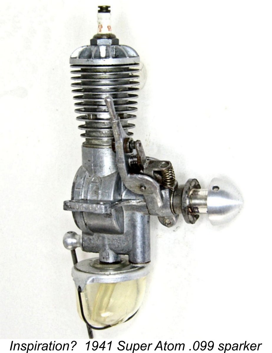
Mr. Haruyama was among the talented individuals who set out to tap into the new post-war market, initially with his Haru line of model engines. His very rare early Haru units were quite interesting if somewhat imitative designs, clearly owing much to the earlier pre-war Atom and M&M engines from the USA. Presumably someone had shown examples of these models to Mr. Haruyama and that was all that it took, as mentioned earlier!
The previously-cited July 1946 "Flying Models" article written by Frank Nekimken included an illustration of a couple of commercially-produced Japanese model engines. One of these was specifically stated to be a post-war production. Although unidentified in the article, it seems to me to be beyond doubt that this was either a TOP or a Haruyama product. If the latter, this would prove that Mr. Haruyma's earliest engines had already appeared by the first half of 1946.
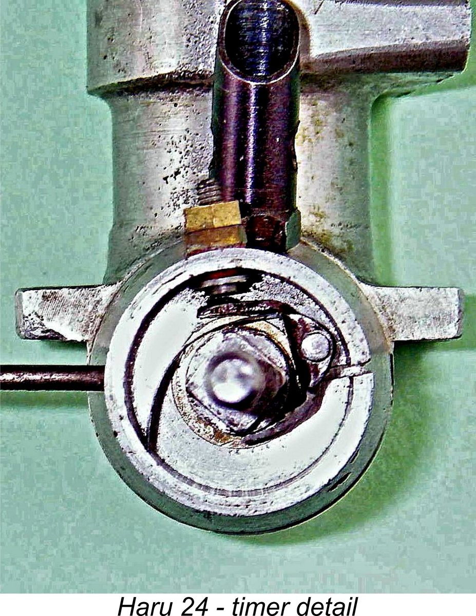
Apart from the piston valve and the prop spinner nut, the obvious Atom influence is confirmed by the use of a "snap-action" timer which is a straight copy of an Atom assembly. Both the piston valve and the timer function perfectly. The engine starts and runs very well indeed - see below. Although at present I have absolutely no direct evidence, the possibility exists that the TOP engines may have been designed originally - or their design significantly influenced - by Mr. Haruyama. The original TOP engines certainly shared many architectural and design attributes with their Haru counterparts, very much including the use of piston valves. The fact that my .097 Haruyama engine bears the model name PEAK (a synonym for TOP) may have some significance in this regard.
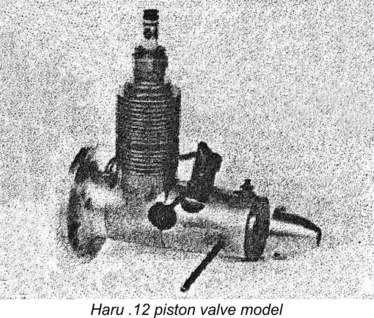
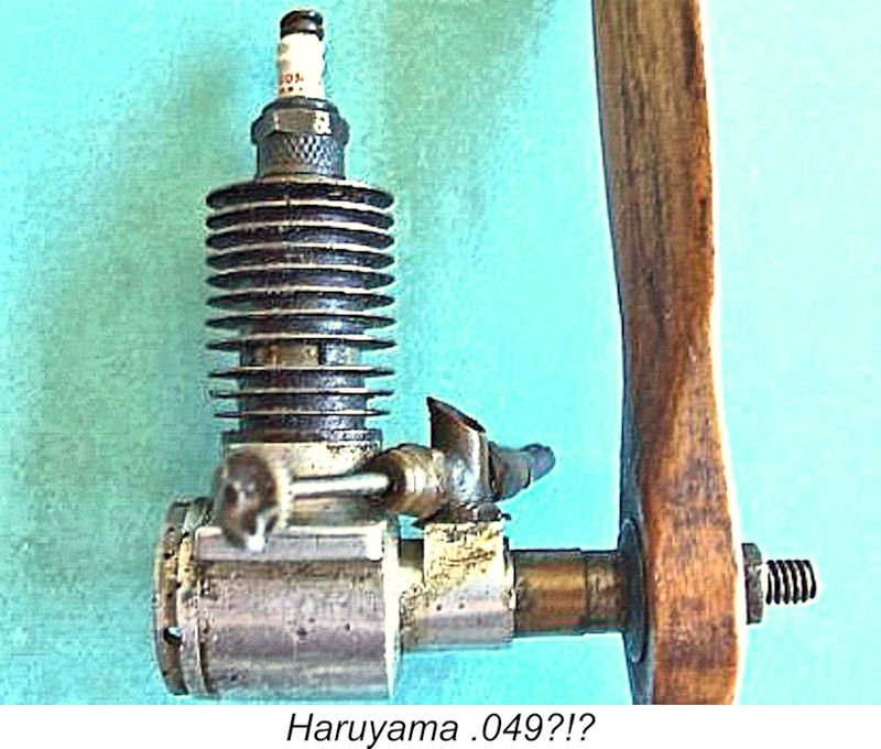
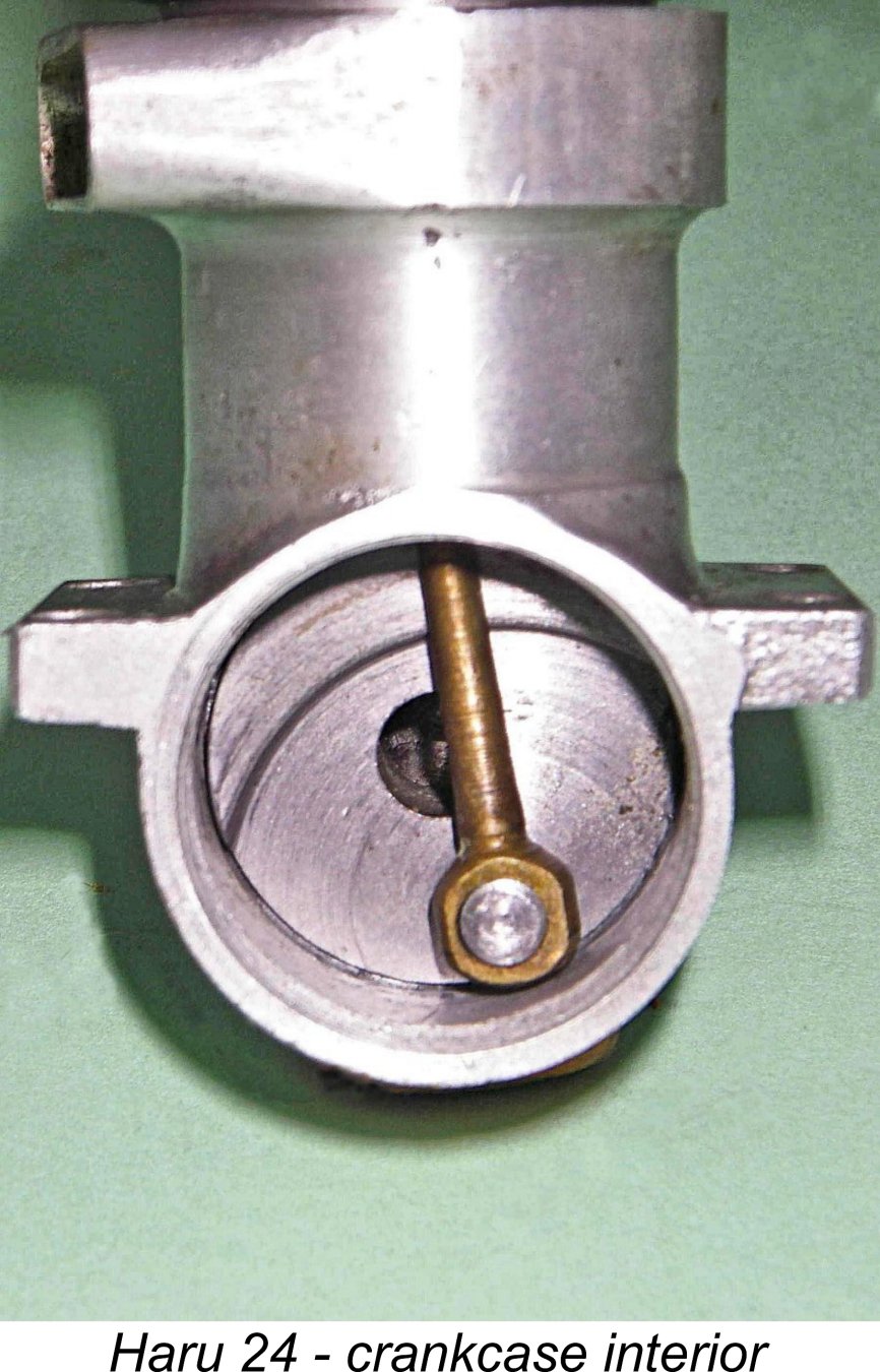
In addition to my own Haruyama .097 cuin. (1.59 cc) unit, I have documentary evidence of a .12 cuin. (1.97 cc) piston valve Haru model having an enclosed timer as opposed to the "snap-action" assembly featured on the smaller model. Apologies for the very poor quality of the attached image showing the Haru .12 model, but it's the only one that I could find! Surely any image is better than none at all?!? The image at least give some shape to the engine. Note the size of the (presumably) 10 mm spark plug in relation to the rest of the engine! There may well have been other models in different displacements. There's some evidence to suggest that Mr. Haruyama may have made an even smaller sparkie having a displacement of only .049 cuin. (0.81 cc). An incomplete and In my view, the identification of the manufacturer was almost certainly incorrect - the engine looks essentially identical to my Haruyama .097 cuin. model which was illustrated earlier. In addition, no working dimensions were made available to confirm the claimed displacement. All that can be said is that scaling of the visible components using the Champion V3 spark plug as a dimensional standard implies a bore of around 10 mm, lending some credibility to the .049 displacement claim. Lacking any further evidence, we have to leave it there. The original Haru models appear to have been designed very much along the lines of the early TOP engines in using a screw-in cast iron cylinder having integrally-formed cooling fins. They also used crankshaft front rotary valve (FRV) induction, again like the TOP designs. The shaft ran in a plain bearing. Finally, the engines featured the piston-valve bypass arrangement. The very close design relationship between the early TOP and Haru models is surely obvious. This similarity underscores the previously-noted possibility that Mr. Haruyama may have been involved with both ranges.
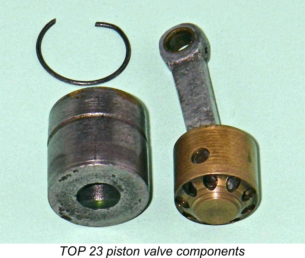
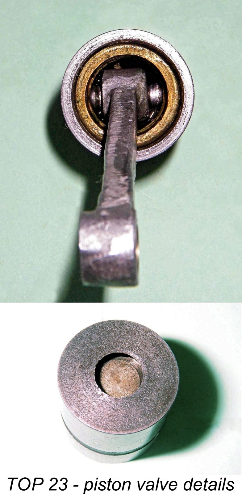
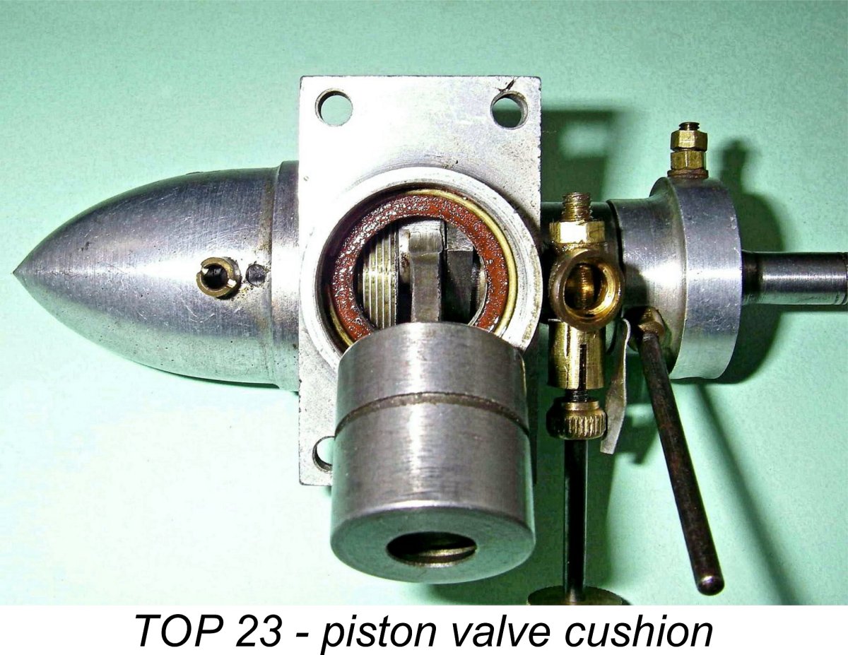
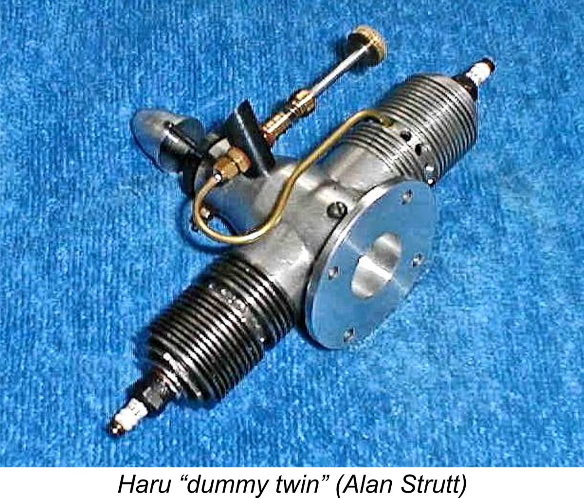
In the piston valve system, the conrod and gudgeon pin are carried in a shuttle piston of smaller diameter than the main bore. This shuttle piston is very The shuttle piston is retained in the working piston using an internal circlip around the base. When pushed upwards within the working piston, it seats at the top against the underside of the working piston crown using a conoidal interface similar to that used in the valves of full-sized automobile engines. Further upward movement of the rod naturally causes the two piston components to rise as a unit. Venting is provided to allow gas to pass freely through the interior of the shuttle piston around the conical seating area. There is a central hole in the crown of the working piston which is closed by the shuttle piston when it is pushed up within the working piston to seat against the underside of the crown. Thus as the piston rises against compression the hole is sealed and the composite piston is able to provide the required seal both on the compression and power strokes. The pressure on the top of the working piston naturally increases the closure pressure on the piston valve - the higher the pressure, the tighter the seal. The seal is maintained until the exhaust ports open and the gas pressure above the piston is relieved. Even then, the inertia resulting from the fact that the piston assembly is now rapidly decelerating as the crankpin swings towards the bottom of the stroke would keep the valve closed were it not for the fact that an internal ledge (often cushioned by a fibre washer) is provided at the top of the crankcase casting which limits Once the working piston has stopped, the internal shuttle piston continues to follow the con-rod by descending inside the working piston, thus opening the valve and allowing the passage of transfer gas through the shuttle piston and thence through the central hole in the crown of the working piston. As the rod and attached shuttle piston pass through bottom dead centre and begin to move upwards on the compression stroke, the shuttle moves up within the still-stationary working piston to first close the piston valve and then cause the working piston to rise again with the valve now closed and ready to resist compression and combustion pressures. Thus the cycle is repeated. Complicated though this arrangement may sound, a recent very successful test of a similarly-designed TOP 23 sparker demonstrated to my own satisfaction that it works remarkably well. That having been said, the system is mechanically ill-adapted to high speed running, also creating a somewhat constricted transfer gas pathway along with a limited transfer period. Not being connected to the gudgeon pin, the working piston is free to rotate within the bore during operation. This factor combines with the impact of repeated valve closures to maintain a good lapped mating fit between the sealing surfaces of the shuttle and working pistons. In addition, the repeated passage of gas In addition to the single cylinder engines described above, Mr. Haruyama also produced a few examples of a “dummy twin” along the same lines as the Lionheart dummy twin marketed in England by Premier Aeromodel Supplies of Islington in North London. Like the Lionheart, the Haru “twin” was actually another single cylinder piston port unit in which one cylinder incorporated the working bore while the other was a dummy which looked the same but actually functioned as the fuel tank. The intended application was doubtless for scale models. I’m indebted to Alan Strutt for sharing the attached image. Many of these early Haru productions were identified by a simple H cartouche, while some (like my .097 cuin. sparkie) displayed the full HARUYAMA name. Others carried no identification at all. Later models were identified by a cartouche incorporating the HARU name. During the mid 1950’s the simple H cartouche came back into use for a time prior to the introduction of the Sky Queen series, of which more below in its place. It should be apparent that the piston port system was inherently limited to operation at relatively modest speeds. This being the case, it was inevitable that the arrangement would soon be overtaken by more up-to-date designs featuring more conventional bypass/transfer arrangements. Mr. Haruyama was clearly well abreast of these developments. In 1947 or perhaps 1948 he produced a completely new design featuring cross-flow loop scavenging. Since I have an example of one of these engines available for examination and test, it’s possible to discuss this model in some detail. I will do so in a subsequent section of this article. But before I get to that, it seems worthwhile to spend a little time describing a limited test of the Haruyama .097 piston-valve sparkie mentioned earlier. The Haruyama "PEAK" Piston-Valve Model on Test
The really interesting point is the way in which this engine is marked. The name “HARUYAMA” appears stamped neatly onto the front of the crankcase (obscured by the fuel system in the attached image), while the name “PEAK” (note - a synonym for “TOP”!) appears stamped onto the left mounting lug. The serial number 138 appears on the right-hand lug.
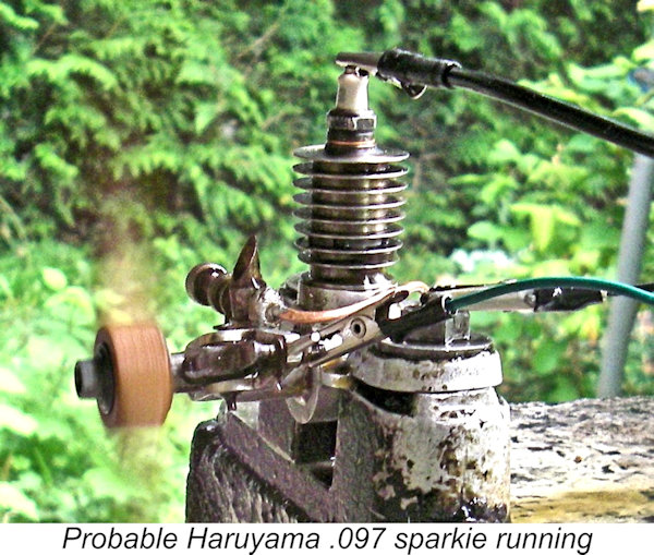
This engine was accompanied in the same multi-engine eBay transaction by another 1.59 cc piston-valve sparkie which was un-marked in any way but appears to be another Haruyama model, albeit having a slightly different external appearance. Quite apart from sharing the same bore/stroke dimensions, it also displays the same integrally-finned cylinder, piston valve, screw-in brass intake, screw-on back tank, copper fuel line, 6 mm plug thread and “snap-action” timer which are all features of the certified Haruyama "PEAK" example. It thus seems highly likely that it is another Haruyama product – perhaps a prototype. Unlike its companion, it is clearly used, but remains in excellent condition.
For conservation reasons, the tiny filler holes in the fuel tanks couldn't be enlarged, forcing me to use a fine-tipped syringe for filling. I had to re-cut the thread on the short-reach AC spark plug which accompanied the second engine – some previous owner had tried to force the ¼-32 AC into the 6 mm installation thread, without getting it home and thankfully without damaging the engine. A ¼-32 thread can easily be re-cut to M6x0.75 – they’re very close. Conservation demands that we re-cut the plug thread, not the installation thread!
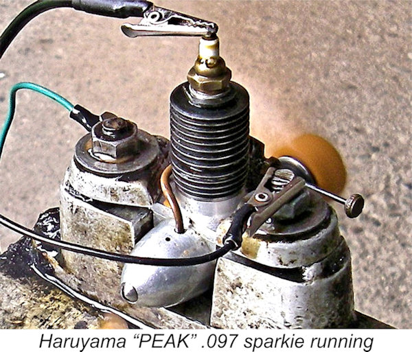
The Haruyama “PEAK” unit turned the test prop at a smooth 7,100 RPM (around 0.065 BHP at that speed), while its un-marked partner was only around 400 RPM down, spinning the 8x6 at 6,700 RPM. Pretty good for a pair of early post-WW2 sparkies of this displacement! Although I have no data on the actual power curves, I'd hazard a guess that the 8x6 would be a pretty suitable flight prop for use with these engines. I have to say that I was quite impressed with the quality, handling and performance of both engines. They appeared to have the potential to provide their owners with long and dependable service. Both of them displayed more than enough "urge" to fly a lightweight sport model provided a suitable lightweight airborne ignition support system could be arranged. Omedeto gozaimasu, Haruyama-san!! The Haru .24 Spark Ignition Model
Although this transition was well underway in America and elsewhere by early to mid 1948, it took effect somewhat later in Japan. The commercial miniature glow-plug had been introduced in America by Ray Arden in November 1947 and had caught on immediately among both model fliers and engine manufacturers. However, the new technology did not take root commercially in Japan until late 1948 or early 1949. In large part, this was due to the near-impossibility of obtaining the required platinum-iridium wire in Japan at this time. Small batches of such wire were supplied to Japanese makers by US servicemen such as Jerry Asner, who supplied wire to the Enya brothers and later acted for a time as their US distributor. However, all of the new model engines introduced in Japan during 1948 continued to use spark ignition, even those from a major domestic manufacturer like O.S.
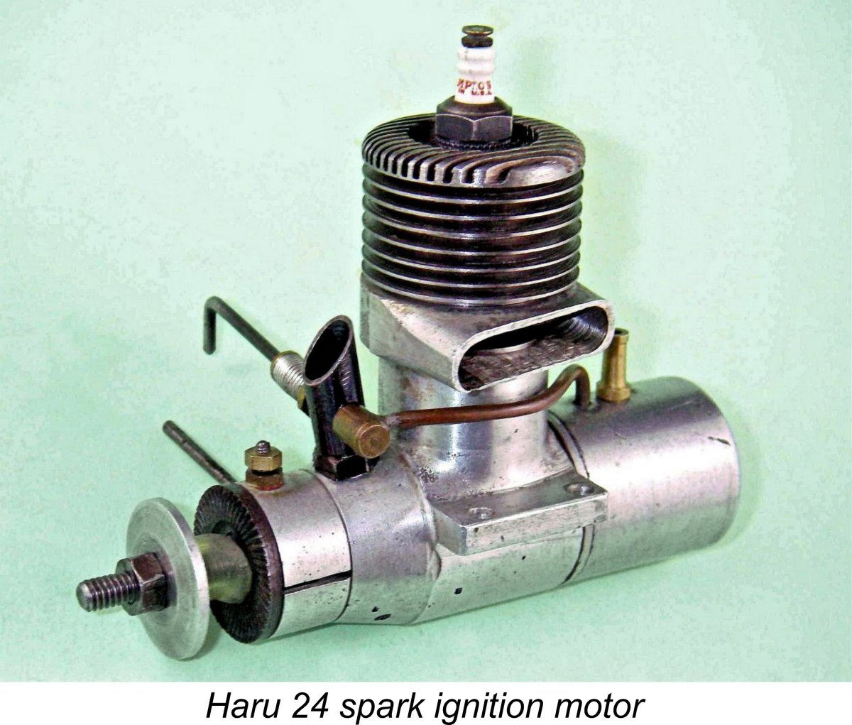
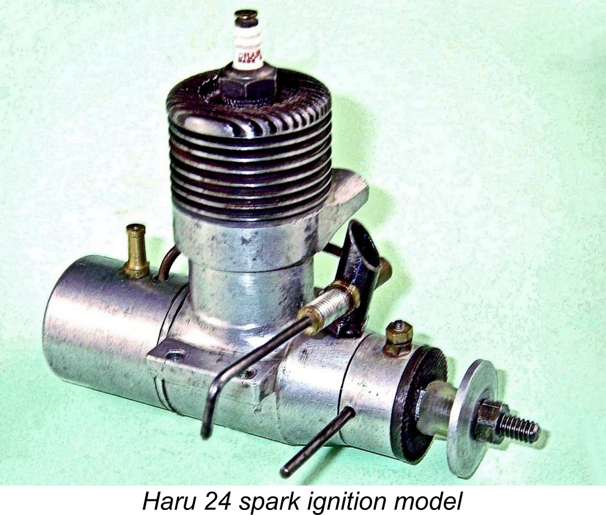
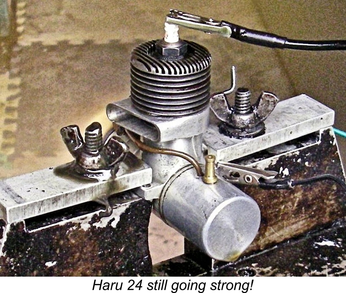
Consequently, apart from the large racing models for which spark ignition was still preferred by many users due to its precise ignition timing control, all of the engines released in 1949 and beyond by Japanese manufacturers were glow-plug models. Many of these 1949 releases were converted spark ignition designs dating from a year or two earlier. It appears that the Haru .24 glow-plug model was among them. Since the earlier spark ignition version of that unit is all that’s available for examination, I’ll focus my comments upon that model. It’s immediately apparent that from the bottom of the exhaust stack down, the new model was essentially identical to the previously-illustrated piston port .12 cuin. design which had preceded it. The most notable difference was the switch to beam mounting, involving the addition of beam mounting lugs to the case along with the elimination of the former radial backplate mount.
The engine was entirely based upon screw-in components, no assembly screws being used. This must have posed some significant assembly challenges since the alignment of the various screw-in components had to be correct for the engine to function. Presumably this was achieved either through selective fitting or through the use of shims/gaskets of differing thicknesses. Given the improbability of re-establishing the correct cylinder alignment, I have elected not to disturb the cylinder of my example of the engine. The Haru 24 was built up around a sand-cast crankcase which was extensively machined and highly finished both inside and out. My example bears no markings whatsoever. The screw-in cylinder was machined from a steel billet. It incorporated a blind bore, with the actual head being integral with the main cylinder. Both head fins and cylinder fins were machined onto this one component, which must have been quite time-consuming to produce. The head was centrally drilled and tapped to accommodate a ¼-32 long reach plug. Measured compression ratio is 7 to 1, which was probably about as high as it could be set and still leave headroom for the upstanding baffle on top of the lapped cast iron piston. This baffle was curved in order to minimize its The backplate screwed into the rear of the crankcase in the conventional manner. However, this arrangement was greatly complicated by the fact that the tank too is a screw-on component, engaging with a suitably-threaded shoulder at the rear of the backplate. This means that when the tank is fully tightened onto a fully-tightened backplate, it has to be in the correct alignment to keep the fuel filler spigot upright and accept the 2 mm brass fuel line. Gaskets of differing thicknesses may have been used to achieve this. The use of the brass fuel line is another persuasive indicator of a 1947/48 date for this engine. Until 1949, it appears that flexible plastic fuel tubing was more or less unobtainable in Japan. Practically all Japanese engines dating from before 1949 used brass fuel tubing of the type seen on the Haru 24.
Having got the backplate off, I was able to confirm that the conrod is turned from bronze. The bearings at both ends are extremely well fitted. The full disc crankweb has a modest counterbalance added opposite the crankpin. I can’t go further with an internal description due to my unwillingness to disturb the cylinder. At the front, the timer is an extremely well-made and highly functional enclosed design which appears to be a re-scaled version of the timer featured on the previously-illustrated Haru .12 model. It provides a dwell period (the It’s possible to see that the crankshaft operates in a bronze bushing. The intake venturi is a screw-in type made from chemically-blackened brass - a typical Japanese arrangement at the time which had appeared on the earier Haru piston-valve engines. The externally-threaded needle is tensioned by a coil spring which gives it a very smooth feel in operation while also offering excellent stability. If my example is typical, it must be said that the Haru engines were extremely well made. In fact, the quality of construction matches or exceeds that of many quite highly regarded contemporary products from America and elsewhere. That’s about all that I can tell you about this engine at the present time. However, a physical description is one thing - an actual bench test is quite another! Let’s set the Haru 24 up on the test stand and see how it performs! The Haru 24 on Test
The presence of the fixed brass fuel line meant that I had to use the standard back tank for all testing - there’s nowhere to connect a flexible fuel line. I took the precaution of checking that the fuel line was clear - sometimes an issue with older engines that may not have been run for decades. I set the Haru up in the test stand, fitted a 10x6 Top Flite Power Point wood prop and checked the timer function using a small continuity tester. I used the same handy device to set the timer so that the points opened just before top dead centre. Everything checked out perfectly. I then connected the Larry Davidson ignition system, filled the tank, set the needle by guesswork at 1¾ turns, administered a few choked turns and a small exhaust prime, switched on the ignition and was all set.
Further starts showed that the engine liked a small exhaust prime for starting. It also displayed a preference when cold for having the needle opened a little from the running setting. If this procedure was followed, starting was invariably completely straightforward - one or two flicks was all that it ever took. Once running, the Haru performed flawlessly. There was no indication of any timer shortcomings at any speed tested - the dwell period appeared to be more than adequate. The engine displayed a lovely break between two and four stroking - in the very best C/L stunt tradition in fact. Running was perfectly smooth at all times, while vibration remained well within acceptable limits. The engine ran the tank out cleanly, taking a considerable time to do so. The following performance data were extracted during this test.
Based on these results, the Haru 24 appeared to develop a peak output of around 0.108 BHP @ 7,400 rpm. Not a stellar performance by any means, but the engine did show itself to be a very user-friendly powerplant which would doubtless give good service in a model. It also appears to be very durable - no mechanical issues were experienced at any time. All in all, a most satisfactory test! Breaking New Ground - the Haru .049 Glowplug Model
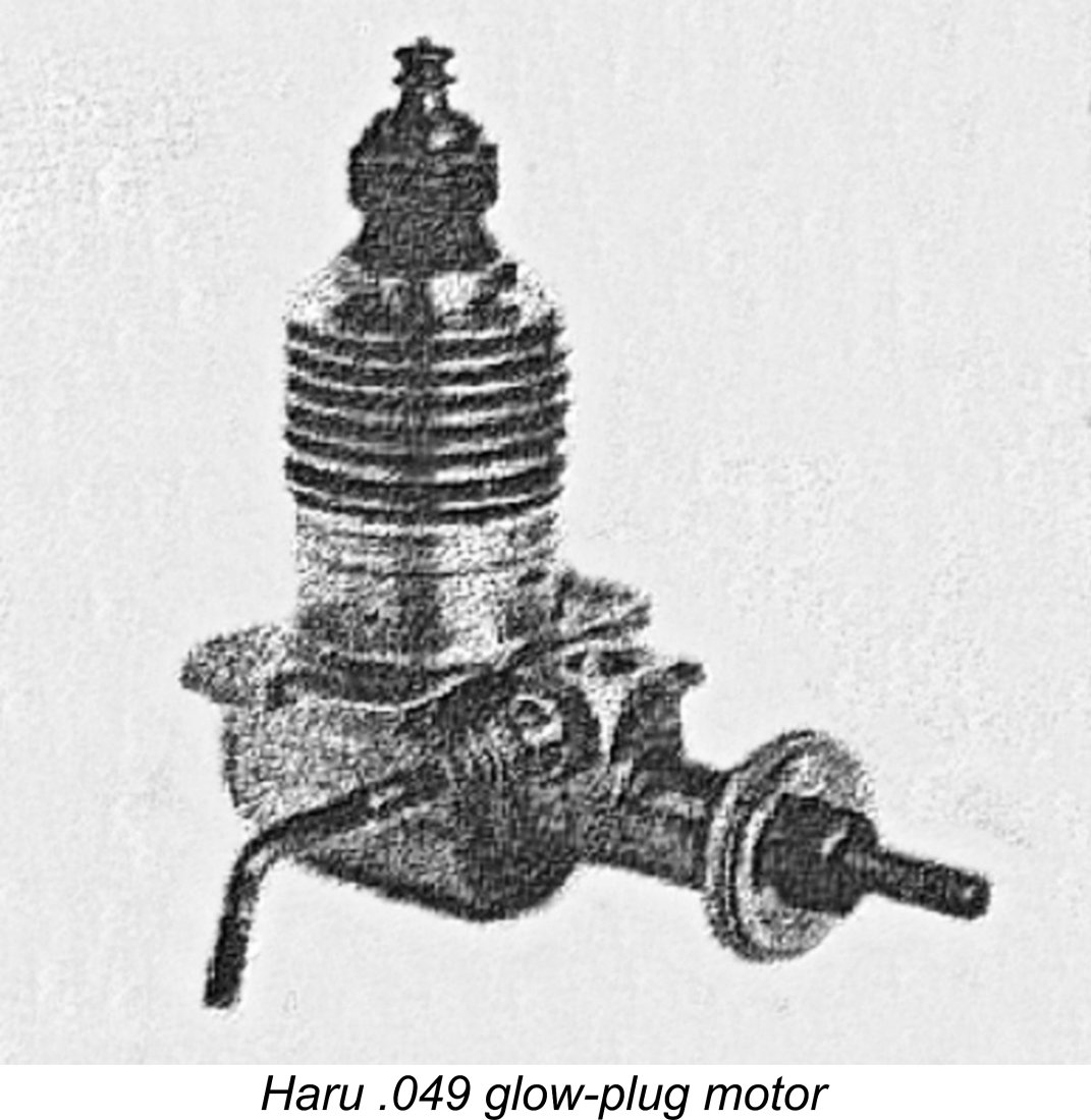
Apologies for the poor quality of the attached image, but once again it’s the only one that I’ve been able to find. I've never encountered an actual example of this model in many years of looking. Although it has a strong claim, there’s some question regarding whether or not this was the first .049 model to appear in Japan. No less an authority than Peter Chinn specifically stated that the first Japanese .049 was the ROC .049 which has been reviewed in detail elsewhere. This engine seems to have appeared in 1950, being very closely followed by a competing .049 model from Fuji. Chinn seems to have been unaware of the Haru .049 model. The actual order of appearance of the ROC and the Fuji cannot now be determined with any authority. However, on architectural grounds it seems very likely to me that both of them were preceded by the Haru .049. That said, the issue of precedence really doesn’t matter very much in my opinion - suffice it to say that all three models were early in the field. Pending an opportunity to examine an actual example of the Haru .049, that’s about all that I can say about this obscure and seemingly mega-rare model. I just felt that it was important to note its existence. On to Bigger Things - the Haru 49
Although once again I have elected not to disturb this used and apparently well-settled example, a certain amount of information can be provided nonetheless. Like its .24 cuin. predecessor, the engine is built up around a sand-cast crankcase and main bearing housing which are once again quite highly finished. A lot of hand-work seems to have been involved. In design terms, this model defines a combination of features which might be considered to represent the Haruyama design signature for the larger models. These are; a plain bronze-bushed main bearing used in Bore and stroke of the Haru 49 are 21.70 mm and 21.50 mm respectively for a displacement of 7.95 cc (0.485 cuin.). The engine weighs in at a rather porky 297 gm (10.48 ounces). Measured compression ratio is 8 to 1. The quality of the Haru 49's construction is quite beyond reproach - close to "model engineer" standard. My example of the Haru 49 had clearly seen considerable use, but remained in excellent mechanical and cosmetic condition. I had no qualms about giving it a few test runs to assess its performance potential. For these tests I used a fuel containing 5% nitro along with 30% castor oil. I anticipated that the engine would be more about torque at moderate speeds rather than all-out power, choosing my test props accordingly. Although it has undoubtedly seen some use, my example is actually still very much on the tight side. I found that the piston/cylinder fit remained sufficiently tight that the engine could "dry-seize" solid if any attempt was made to turn it over after solvent cleaning but before oiling had taken place. Both heat and penetrating Despite this, when set up in the test stand and lubricated with an oily castor-based fuel, the engine felt superb - any diesel manufacturer would be praised very highly for achieving a compression seal this good. The "dry seizure" problem was completely eliminated by the presence of the oily castor-based fuel that I was using. All bearings felt fine also, with no detectable play anywhere. Having tested an example of the Haruyama-designed Sky Shark 49 on a previous occasion, I had a fair idea of the range of test props which would likely yield the most informative data. I began with an APC 12x6, which the very similarly configured Sky Shark had turned at 7,800 RPM (see below). With this prop fitted, I donned my industrial-grade ear-muffs, opened the needle around 4 turns, choked to fill the fuel line, shot a few drops of fuel down the intake, administered a moderate exhaust prime, lit the plug and hit the prop.
Having completed that task, I set about taking some prop/RPM measurements for a range of suitable airscrews. The engine exhibited a lovely 4/2 break - it would make an excellent control line stunt powerplant. When leaned out, it ran extremely smoothly. I kept the fully leaned-out runs fairly short in deference to that tight piston/cylinder fit, but the engine actually displayed no signs of an incipient nip-up at any time. At the higher speeds tested, vibration levels were beginning to climb, although they remained within manageable limits at what turned out to be the engine's peaking speed. The major negative observation during this test was the rather alarming rate at which fuel was being consumed. I was using a fairly large translucent R/C model boat tank, and the rate at which the fuel level dropped seemed akin to watching a bath-tub of water drain when the plug was pulled! You'd have to be very well-heeled to keep this engine supplied with fuel having even a modest nitro content! Regardless, I persevered, re-filling the tank at regular intervals. The following data were recorded.
As can be seen from the above data, the Haru 49 developed a peak output of around 0.473 BHP @ 9,500 RPM. The engine ran very well at all speeds tested, but torque and hence power output seemed to go over a cliff at around 10,000 RPM. While this isn't exactly a stellar performance even by early 1950's standards, the engine proved to be a serious torque-producer which could swing a prop of quite meaningful size at a useful speed. That is clearly what it was designed to do. A 12x6 airscrew would appear to be an ideal flight prop. The engine's superb quality, sturdy construction and excellent handling would have endeared it to any owner having realistic performance expectations along with an ability to cover the fuel bills! For completeness, it seems appropriate to conclude by spending a little time discussing the seemingly-related Sky Shark 49 which appears to be a near-contemporary of the Haru 49 just evaluated, also sharing many of its design features. The Sky Shark 49
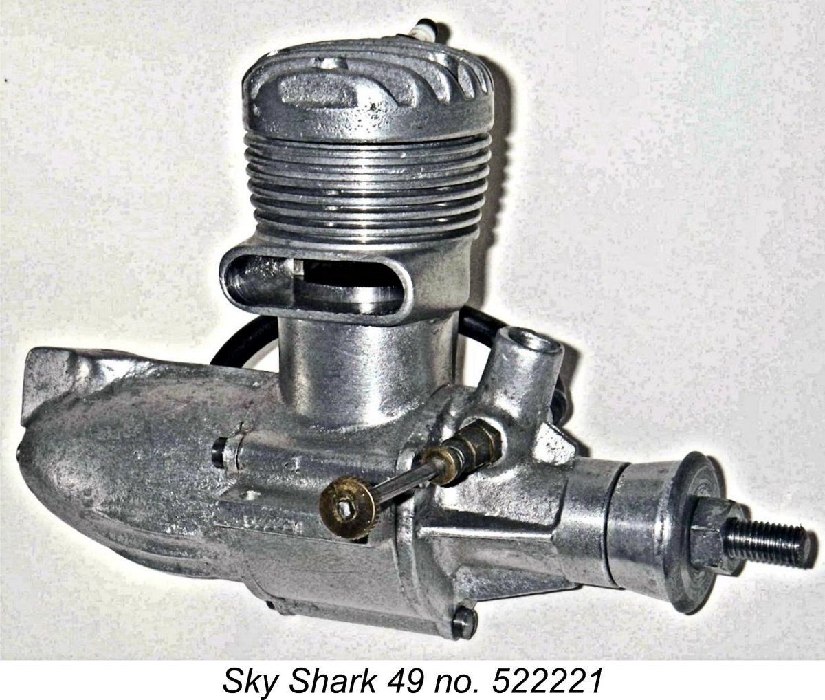
Suffice it to say that the Sky Shark was a massively-constructed glow-plug unit once more displaying all of the previously-listed features which might be considered as constituting Mr. Haruyama’s design signature. It featured a separate main bearing housing which was attached using three bolts, along with the rather unusual 5-bolt cylinder head and lapped piston with a curved baffle. The glow-plug was installed from the transfer side and was very steeply angled - almost horizontal, in fact. A bronze-bushed main bearing was once more used in conjunction with FRV induction. Measured bore and stroke of the Sky Shark were 21.0 mm and 23.0 mm respectively for a calculated displacement of 7.97 cc (.486 cu. in.). This made the engine a long-stroke unit, in sharp contrast to the other Haruyama designs discussed here. The Sky Shark weighed in at a very hefty 337 gm (11.9 ounces) complete with tank, plug and fuel tubing.
I had previously run a full test of the Sky Shark 49 in connection with my earlier article about that engine. I found it to be a very fine starter and a smooth runner up to around 9,500 rpm, where the ignition timing seemed to become over-retarded, perhaps due to the compression ratio of 7:1 being a bit too low for higher-speed running on the low-nitro fuel that I was using. In addition, the relatively inefficient combustion chamber configuration and plug location may have had a negative effect upon performance. Perhaps because of this, the engine proved to be a bit down on peak power, only managing around 0.400 BHP @ 8,000 RPM and hence not quite matching the Haru 49 tested for the present article. However, there was plenty of lovely low-end torque on tap! The following prop/rpm figures were obtained.
All examples of the Sky Shark were reportedly manufactured between 1952 and 1954. They seem to have been produced in very small numbers - well-informed contacts in Japan were able to report only two other known examples apart from my own pair, and neither of them were apparently complete. A small workshop-scale production facility is implied here. Taken together with the production differences noted above, this might be taken to imply that the Sky Shark was actually produced by someone other than Mr. Haruyama, although there seems to be no doubt that he was involved with the design. It’s actually possible that limited production of the Haru 49 continued during this period, although we have no way of confirming this. Later Developments - the Sky Queen Engines
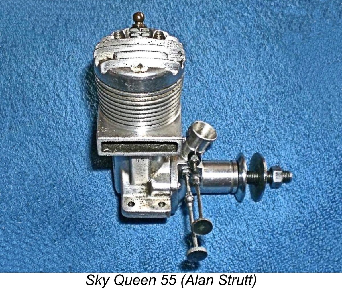
However, at some later point during the mid 1950’s Mr. Haruyama changed the name of his range to Sky Queen - a clear progression from the former Sky Shark designation, seemingly confirming some kind of connection. Beginning at some indeterminate point in the mid 1950’s, presumably after the Sky Shark interlude, the almost equally obscure Sky Queen engines were produced in both single and twin cylinder forms. It’s unclear how many different single cylinder models there may have been. Alan Strutt had one of the single cylinder Sky Queen .55 cuin. engines, and there may have been other models having different displacements. Alan was kind enough to take his Sky Queen 55 apart for examination and measurement.
Like its Sky Shark predecessor, the piston has a curved deflector, a feature which was also present in the earlier Haru 24 and 49 models. The crankshaft has a full-disc crankweb with counterbalance as well as a hollow crankpin, exactly like that found in later variants of the Sky Shark. Twin needle valves are featured, representing a rudimentary approach towards the provision of speed control for R/C. The idea was that one needle would be set for flat-out running, while the other would be set very rich for lower-speed operation. A valve would be incorporated to permit switching between the two at will. This initial move towards R/C speed control didn’t last long - by 1959 intake throttles were becoming the accepted standard. This seems to date Alan’s example to the 1957-59 period. The other noteworthy feature of the Sky Queen shaft is the slightly unusual shape of its crankshaft induction port, which has an elongated "race track" shape rather than the more common round hole or rectangular aperture. This represents an advance from the Sky Shark design in that it gives faster opening and closing than a round hole while avoiding the stress-raiser which often accompanies the use of a milled rectangular port.
The illustration appears to confirm Chinn’s understanding that the Sky Queen range was still current as of 1960. However, by 1962 the range seems to have disappeared - there is no mention of any Sky Queen models in the 1962 “Global Engine Review” (almost certainly authored by Peter Chinn) which appeared in the 1963 “American Modeler” annual published in late 1962. So ended one of Japan’s most obscure model engine ranges. As I said at the outset, on the basis of their quality and performance these engines are well deserving of our respectful remembrance! Conclusion I’m sorry that I’m unable to offer any more comprehensive information about these seemingly very rare engines. They certainly merit the attention of anyone having an interest in the early post-WW2 products of what was to become the world-leading Japanese model engine manufacturing industry. If any reader knows more or has other examples which could serve as illustrations, please get in touch! Meanwhile, I hope that what I’ve presented here has done something to raise the profile of these excellent model powerplants! _____________________ Article © Adrian C. Duncan, Coquitlam, British Columbia, Canada First published August 2025 |
||
 I‘ll bet dollars to donuts that very few of my readers will have as much as heard of the model engine range which forms my main subject in this article! I’ll be writing about the Haru range from Japan which had its origins and major market presence during the early post-WW2 period when model-related activities in Japan were well below the radar of the contemporary English-language modelling media. Moreover, the Haru engines never appear to have been exported in commercial quantities, hence being very rarely encountered today outside Japan. Even there, they are reportedly far from common.
 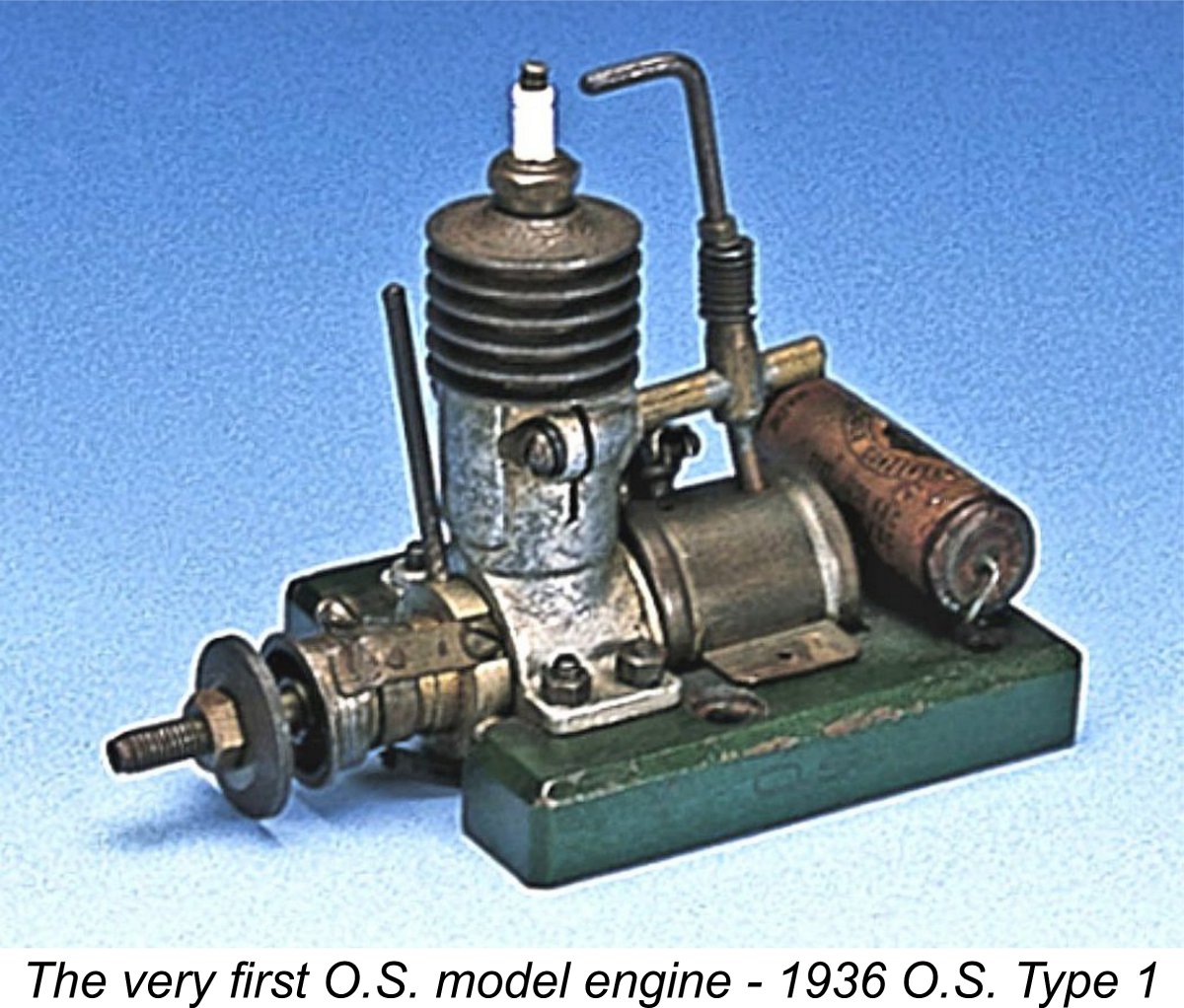 It may seem surprising to some that a new commercial model engine manufacturing enterprise could rise so rapidly quite literally out of the ashes of WW2. The reality is that power modelling had been very popular in Japan prior to that conflict, creating a demand for model engines which could not be filled from outside sources due to import restrictions and other factors. Hence home-grown model engine manufacturing operations such as
 Alan Strutt recalled a conversation that he had years ago with a former American GI who was in Japan with the US occupation forces just after the war ended, quite literally when the bomb craters were still smoking! According to Alan’s informant, it was possible even then to get anything mechanical made by skilled local Japanese craftsmen, and this included model engines. All you had to do was give them a rough drawing or show them an example of an American engine, and within days the locals would be back with their own finished engine, which they would happily sell at a very reasonable price. Consequently, there were lots of unadvertised locally-made engines floating about at the time as people struggled to survive by applying their skills to making anything that they could sell.
 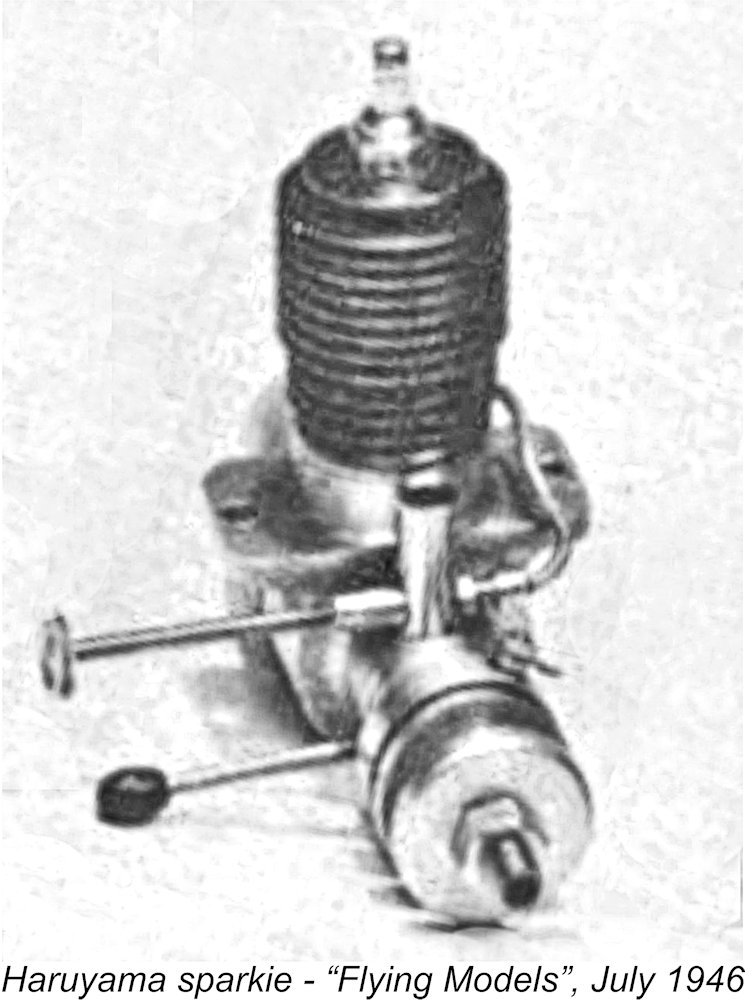 These original Haru models featured piston valves very similar to those used in their American predecessors. They were not alone in this in a Japanese context - the contemporary TOP engines from Osaka also featured such valves. I’ve covered the
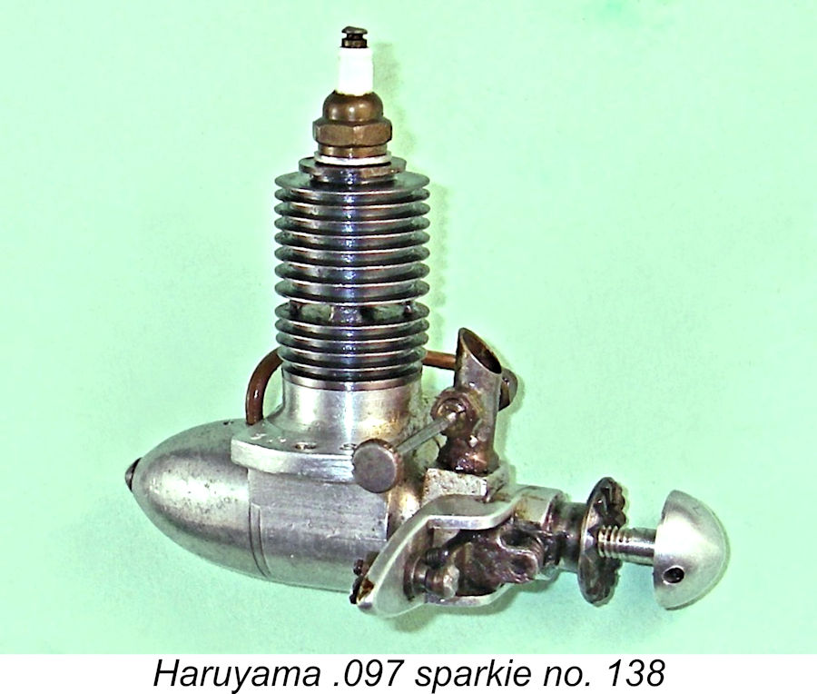
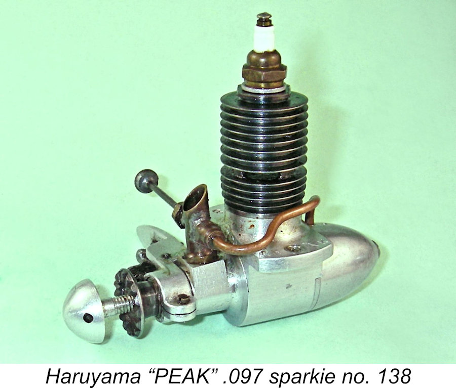 The near-mint example of the Haruyama "PEAK" .097 cuin. sparkie which I was fortunate enough to acquire appeared to be more or less unused. It was complete with its seemingly new 6 mm Japanese spark plug. This one looks for all the world like a reduced-scale early post-WW2
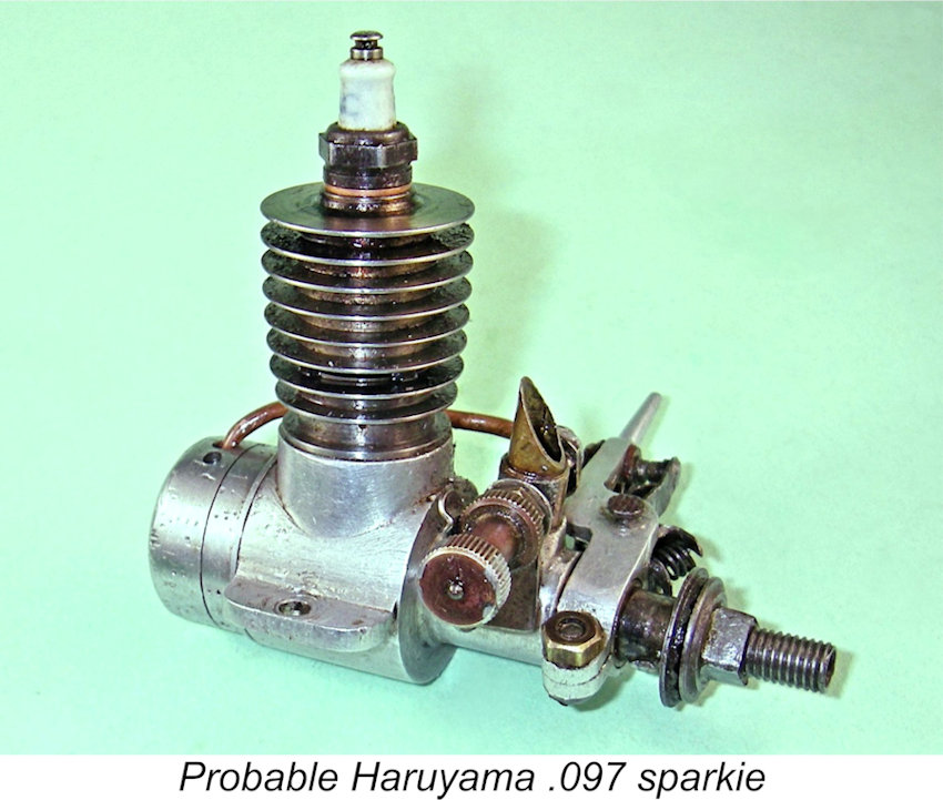
 I’ve assigned an introductory date of 1947/48 to this model because it is known to have been produced in both spark ignition and glow-plug configurations. This places it at the transition point between spark and glow-plug ignition in Japan.
 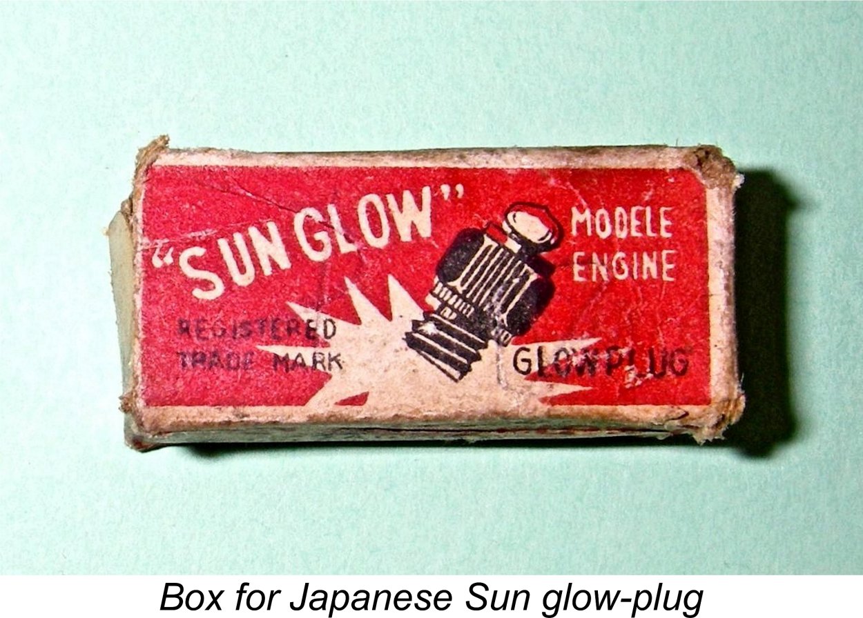 By 1949, things had changed - the wire supply situation had eased greatly. Miniature glow-plugs were now quite readily available in Japan, with domestic brands like Sun and Fuji becoming widely used by Japanese modellers. As of 1949, Japanese model engine manufacturers had well and truly embraced the new ignition technology.
 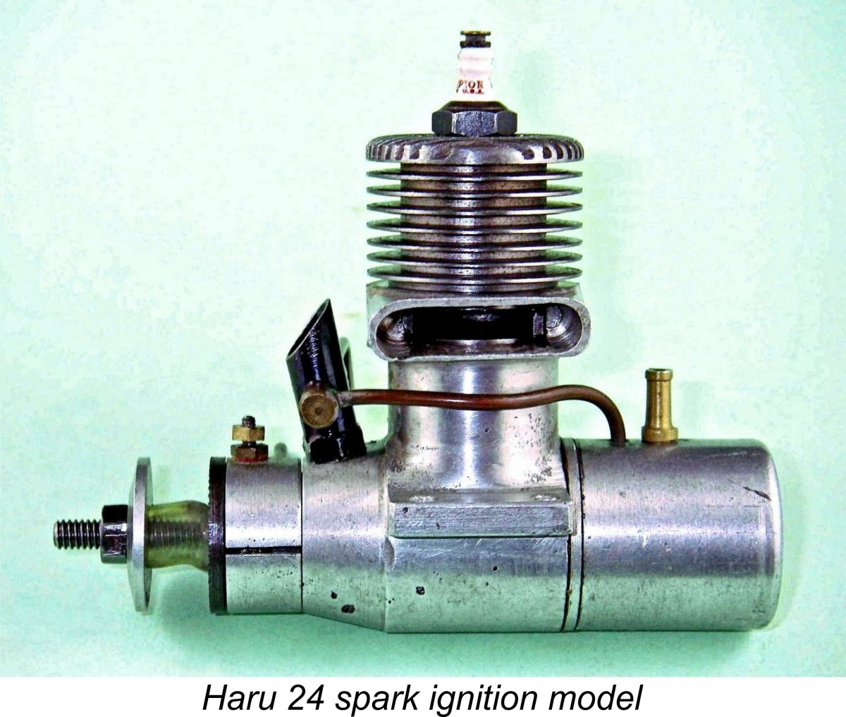 The Haru 24 was a plain bearing cross-flow loop scavenged FRV design of very neat and up-to-date appearance. Unusually for its time of introduction, it was an exaggeratedly short-stroke design, featuring bore and stroke dimensions of 18.30 mm and 15.00 mm respectively for a displacement of 3.95 cc (0.241 cuin.). Weight complete with tank and plug was a commendably light 147 gm (5.19 ounces).
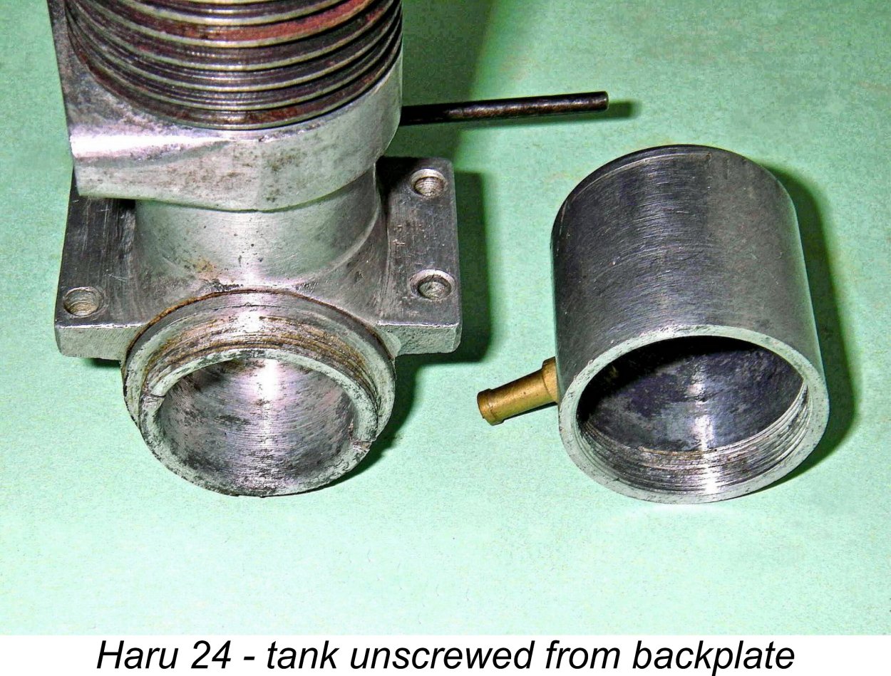
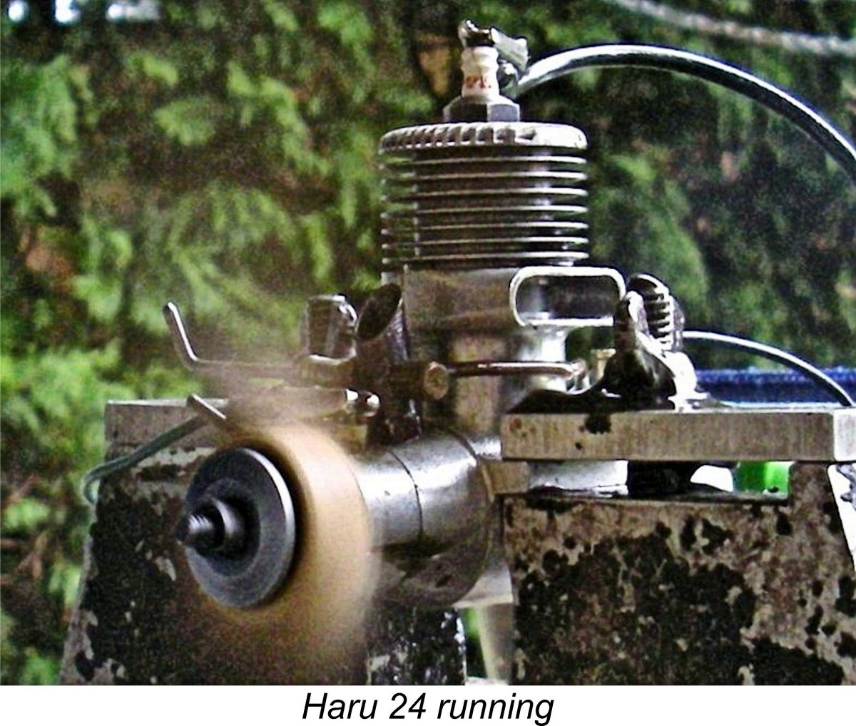
 The Haru recommended itself to me immediately by starting quite literally on the first flick! I’d guessed slightly rich on the needle, but the engine ran steadily nonetheless, waiting for me to fine-tune the settings.
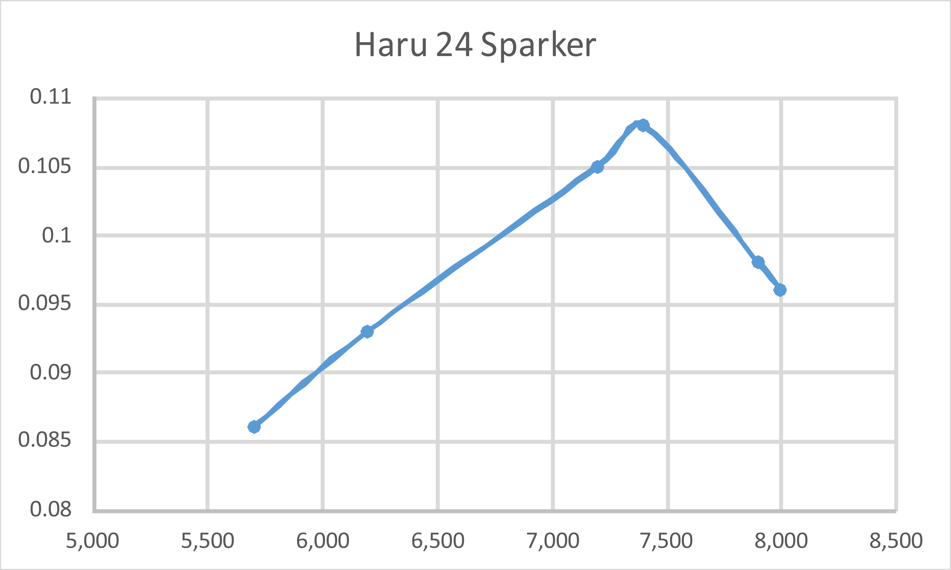
 At some point in 1949 or perhaps 1950, Mr. Haruyama introduced a neat little .049 cuin. glow-plug model. This was presumably inspired by the emergence of a
 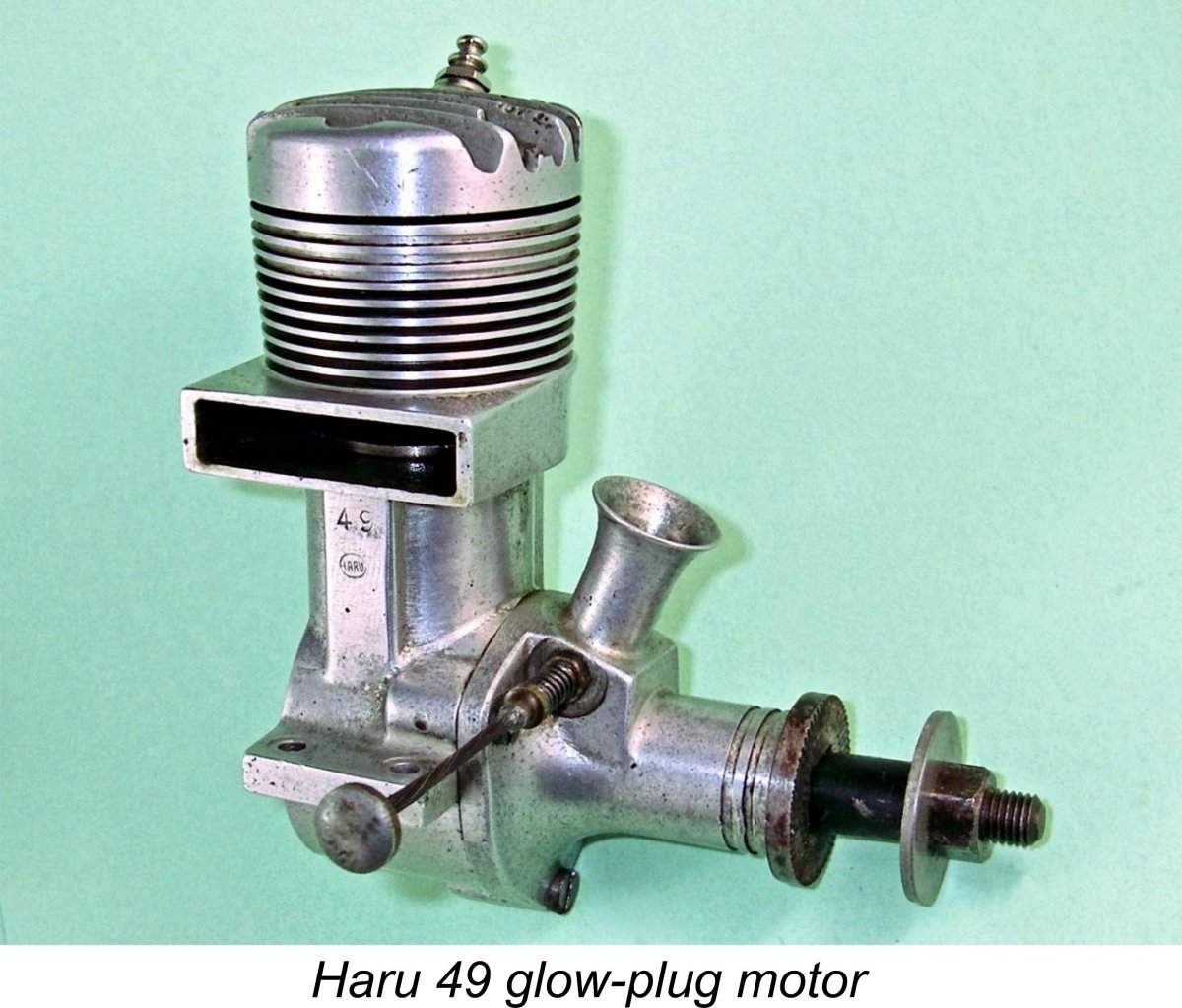 At some point in the early 1950’s, Mr. Haruyama introduced the first of a series of .49 cuin. glow-plug models with which he was associated. Japanese sources confirm that the initial product was simply known as the Haru 49. These early 1950’s engines can be identified by the fact that their crankcases are marked both with the displacement and with a small cartouche containing the full Haru name. My illustrated example is one of these units.
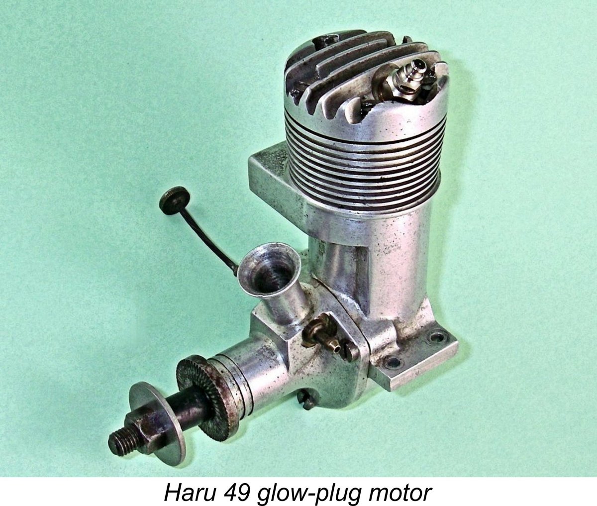
 oil were required to unstick it from this condition! I judged this tightness to be sufficient to affect perfomance to a certain degree, feeling that a slighty less tight fit would probably improve the engine's performance given its use of glow-plug ignition.
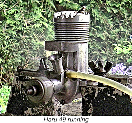
 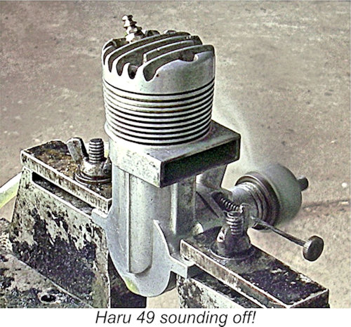 Like its Haru 24 predecessor tested earlier, the Haru 49 endeared itself to me by only needing that single flick to roar into life. And I do mean roar - the thing was extremely loud, to the point that I was immensely grateful for the efficiency of my ear-muffs. The initial start was slobberingly rich - I had guessed wrong on the needle setting. But a quick leaning out soon had the engine running in a smooth four-stroke mode, leaving me with an ample opportunity to obtain the running photos.
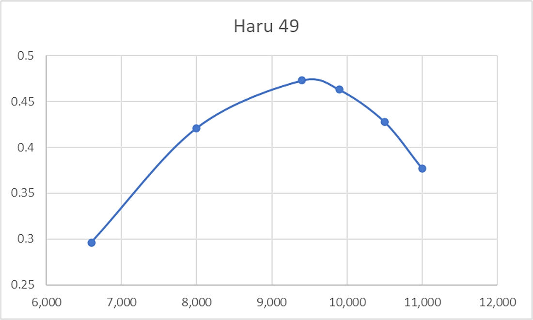
 In 1952 Mr. Haruyama appears to have become associated with a quite distinct glow-plug model, albeit one still having a displacement of .49 cuin. This was the
 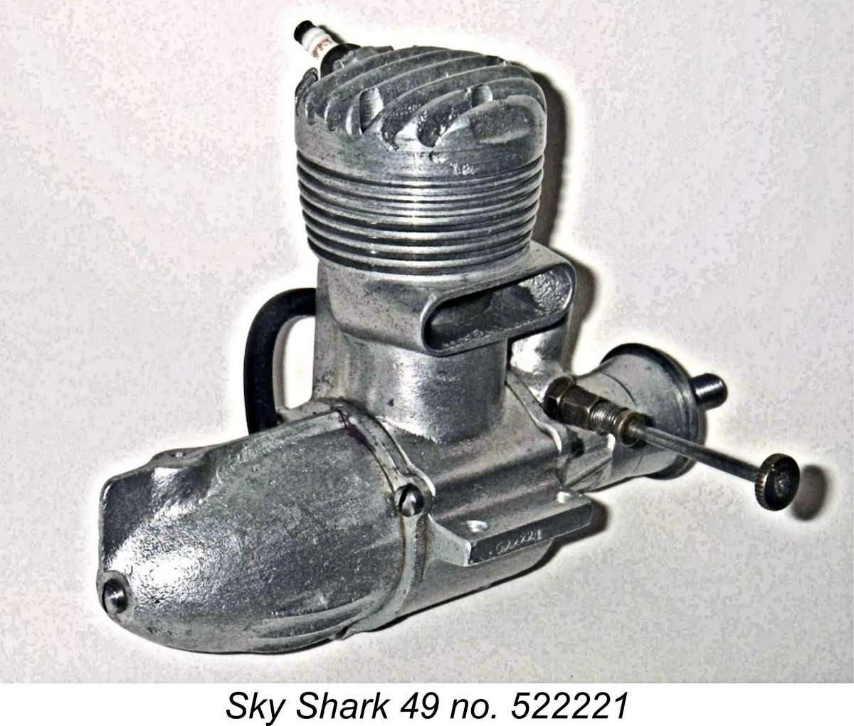 From a production standpoint, the Sky Shark appears to represent something of a side-step from both the preceding and following Haru lines. We’ve seen that prior to becoming involved with the Sky Shark, Mr. Haruyama had tended to produce engines which featured elegantly stylized and polished crankcases. The Sky Shark retains many of the engineering design features of the earlier Haruyama designs but is presented in a very different style with its heavy and rather ungainly sand-castings which are largely left in their as-cast state. It appears that it may have been motivated by a desire to reduce production costs by minimising the finishing effort involved. Alternatively, it may have resulted from a partnership with others in which Haruyama acted in effect as the design consultant but was not involved in the actual production. We'll probably never know ……………..
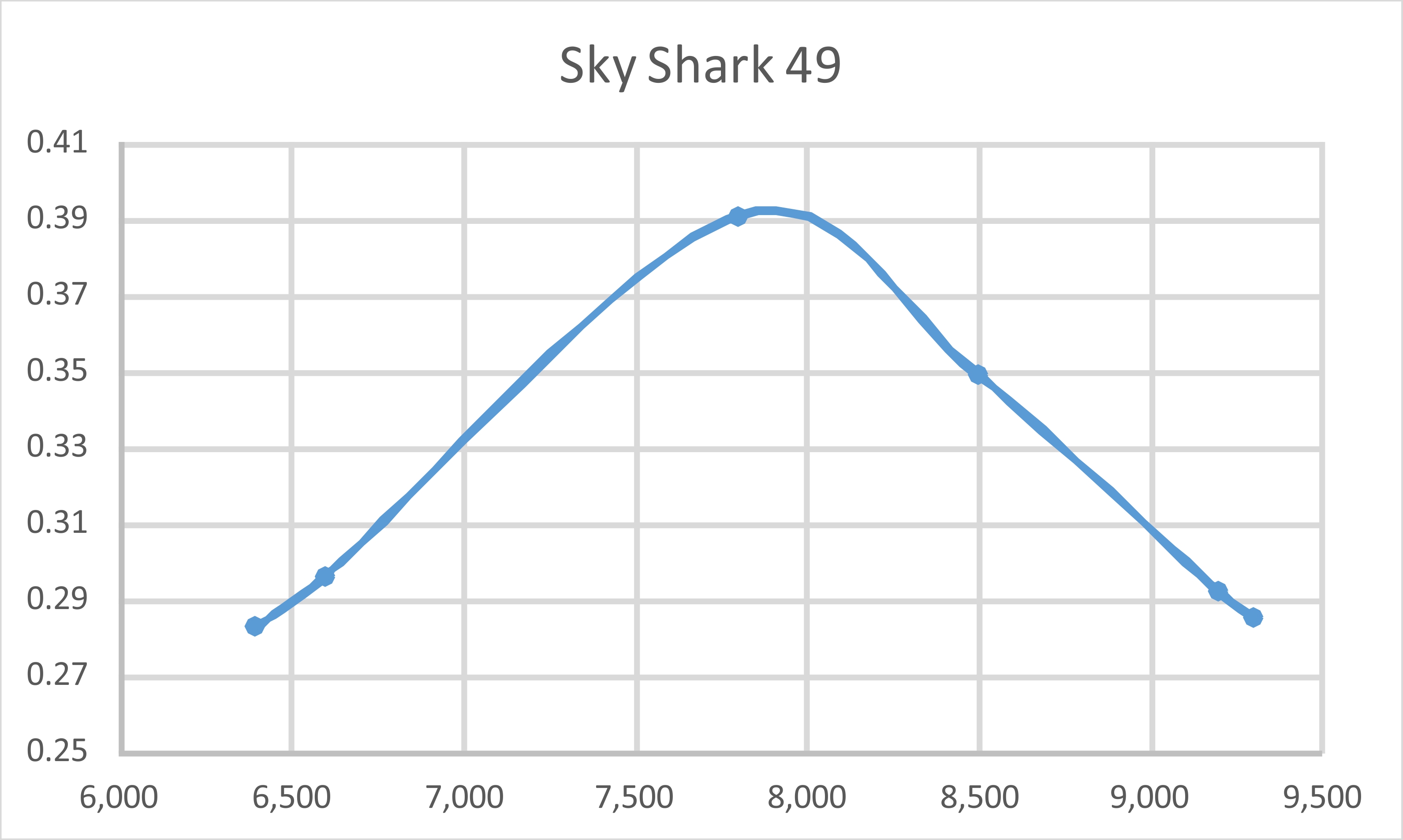
 As of the latter part of 1954 when production of the Sky Shark was winding down, the manufacture of the Haru 49 either continued (assuming that it had in fact been ongoing) or was resumed following a hiatus during the Sky Shark era - we don’t know which. Reportedly the engines now reverted to the former H cartouche used at the very beginning instead of the interim cartouche incorporating the full HARU name.
 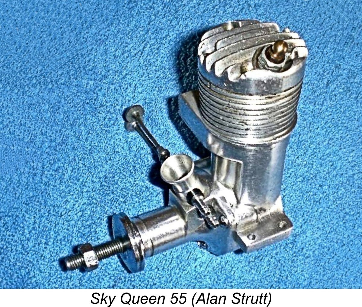 On the basis of its external appearance, the Sky Queen 55 clearly follows the design of the earlier Haru 49 in almost every detail. Bore and stroke of Alan’s engine were measured at 22.6 mm and 21.5 mm respectively for a calculated displacement of 8.63 cc (0.53 cu in.), which is slightly at variance with the 55 designation stamped just below the exhaust port. It will be noted that the engine has the same stroke as the previously-discussed Haru 49 model - the additional displacement was created entirely through a 0.9 mm increase in the bore.
 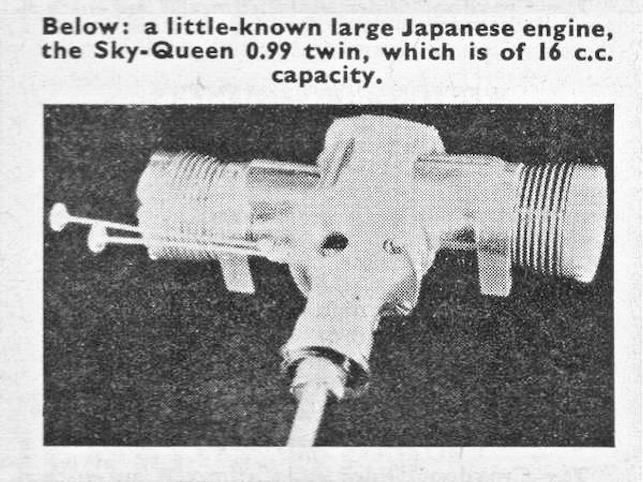 The suggested late 1950’s dating appears quite credible. There is some supporting evidence in the form of a captioned photograph which appeared in Peter Chinn’s “Latest Engine News” column in the November 1960 issue of “Model Aircraft”. This image is reproduced at the right. It showed the opposed-twin cylinder Sky Queen .99 of 16 cc displacement, which also featured twin needles. This engine was apparently created by simply combining two .49 cuin. piston/cylinder sets.
 | |