
|
|
Ivan Rogstadius - Swedish Model Engine Pioneer
However, I admit that the precise dating of said Golden Age depends very much on which of us is talking about it! I’m sure that many present-day model fliers would classify today’s push-button CAD-aided 3D printing-enabled ARTF approach to aeromodelling as a Golden Age! That’s because present-day electric power-plants, control systems, marketing strategies, construction materials and construction techniques have simplified things so much by eliminating many of the former difficulties. Even the physical effort has been largely eliminated through the almost universal adoption of R/C.
Times do indeed change……….. and I accept and understand that, joining with latter-day participants in characterizing myself unapologetically as one of yesterday's modellers, a role with which I'm completely comfortable. I recognize the fact that for many of today's model fliers, these are the Good Old Days - for me, they're long gone outside of SAM circles! Even though the period in question may vary depending upon one’s perspective, the excitement that the Golden Age of my recollections invokes in my otherwise-faded memory seems to remain undiminished. I recall it as a constantly stimulating time during which the hobby was developing rapidly in a number of directions through constant innovation but was still very much based upon individual design insights coupled with hands-on craftsmanship and skill. There was massive scope for creative originality, and you had to do far more than merely open boxes, assemble components, push buttons or move joysticks! It was a great and satisfying time to be an active aeromodeller!
By contrast, most present-day modellers have no need to acquire such skills, getting perfect motor runs each time simply by pressing a button to activate bought-in-a-box technology. Although they'll never realize it, they’re depriving themselves of one of the most enjoyable and satisfying challenges of power modelling in the old days - they'll never experience the joy and satisfaction of getting to grips with the idiosyncracies of those classic model engines and working through the operating challenges to secure that perfect motor run. If the trouble-free push-button flying of models was all that there was to aeromodelling, I'd never have become involved in the first place! Moreover, the variety of different engine design concepts and construction innovations far exceeded those of later years when all lines of development converged upon an optimal design format for each category which became more or less standardized. There was always something new to be experienced! Particular credit must go to the pioneers, who were the first to meet and overcome the successive challenges inherent in the development of a then-new technology. As a confirmed modelling dinosaur, I actually envy them the experience!
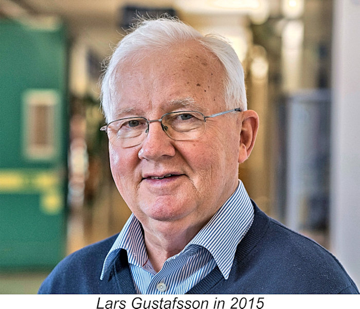
The preservation of the history of engines and associated personalities from what I myself view as the pioneering, vintage and classic eras (very roughly, encompassing the period from 1906 to c. 1970) becomes more challenging with each passing year as those who were “there” at the time continue steadily to leave us, in many cases with their stories untold. Opportunities to obtain first-hand information from actual participants are few and becoming fewer by the year. It won’t be long before such opportunities vanish completely. Consequently, in the majority of cases the only path leading to the re-discovery of the aeromodelling history of the era is the hunting down and interpretation of information contained in old magazines and books which were contemporary with the engines and models described. Admittedly, the increasing degree to which such resources are becoming available on line has greatly eased the task of identifying and quoting them, but it still remains a This being the case, I was delighted when an opportunity presented itself in 2009 to learn at first hand about the early development of model diesel engines in Sweden. This came about entirely thanks to the efforts of my valued Swedish friend and colleague Lars Gustafsson, who was not only able to provide English translations of some key articles from the Swedish modelling media of the day but was also able to track down a key surviving participant, Ivan Rogstadius, who built Sweden’s first home-grown model diesel in 1943 and published full construction details of this engine to popularize this then-new technology in the Scandinavian countries. This article made its original appearance in January 2010 on the late Ron Chernich’s wonderful but now-frozen “Model Engine News” (MEN) website, where it may still be found. I’m re-publishing it here in edited and enhanced form to ensure its preservation as Ron’s permanently locked-down and hence frozen website slowly deteriorates due to an enforced lack of maintenance. Genesis of This Article
Tucked away among the sketches (perhaps unintentionally) were three seemingly-unrelated photocopied pages from a Swedish magazine series showing plans and directions for the construction of a Dyno-like diesel. The name of the magazine was “Teknik för Alla” (a Swedish equivalent of “Newnes Practical Mechanics”) and the series was titled “Här Kommer Miniatyre Dieseln” (Here Come the Miniature Diesels). The author was cited as one Ivan Rogstadius. The photocopied pages contained no apparent publication date, although the date "1944" was clearly discernable at one point in the midst of the otherwise-incomprehensible Swedish-language text.
Some years previously, Ron had drawn up a set of 2D CAD plans for the Swiss Dyno which had been included in his original Motor Boys Plan Book. The Rogstadius 2 cc version appealed to Ron as an engine that could be easily hogged from solid aluminum in the absence of a casting and looked like a good subject for a 3D rendering. Accordingly, a 3D CAD rendering of the engine was created from the “Teknik för Alla” drawings in preparation for the generation of construction plans. But what to call it - a Dyno clone, a Rogstadius, or what? Being too lazy by his own admission to go through the process of converting the photocopies to text for submission to a translator, Ron sent a picture of the engine out to his fellow Motor Boys in November 2009 to see if anyone recognized it.
Seeking further information, I contacted my ever-helpful Swedish mate Lars Gustafsson to inquire if he knew anything about the Rogstadius engine cited by Laidlaw-Dickson. Lars promptly did what Ron and I should have done by using the Internet to discover that Ivan Rogstadius was a noted Swedish model engineer who was born on April 24th, 1915. Even more to the point, he was not only still alive at age 94 but living in Älvsjö, a mere 40 km distant from Lars’s home! This was exciting news indeed! Lars informed us that “Teknik för Alla” had ceased publication in 2001. However, if he was able to talk directly to Ivan, it might be possible to discover and document the origins of the 1944 engine to a highly authoritative level. In hopes that such a meeting might be possible, we primed Lars with a list of questions and prompted him to seek an interview. Equipped with our questions, Lars phoned Ivan to discover that despite his 94 years, he remained active and alert, and would welcome a visit to discuss the Rogstadius engine and its origins. Accordingly, on November 23rd, 2009, Lars visited Ivan at his home to conduct the interview. Quite a story emerged from this interview! What follows is a listing of the questions that we asked Ivan through Lars, along with Ivan’s responses in italics. Lars Gustafsson’s November 23rd, 2009 Interview with Ivan Rogstadius
I A free flight model built by Ivan’s friend Gösta Hellström was fitted with this engine and subsequently tested successfully at Skarpnäck, a small airfield south of Stockholm, in mid-1943. A report of these test flights was published in the magazine “Svensk Flygtidning”, number 7, July 1943.
No, Ivan didn't know anything about the origins of the Mikro engine that was produced in Denmark beginning in early 1945, although he did note correctly that it was apparently identical to the engine described in his drawings. He had no contact with the manufacturers of the Mikro at any time. However, his plans undoubtedly reached Denmark, where they could have served as the basis for the Mikro design.
Ivan didn’t remember either the Typhoon or R-H engines. If R-H stood for Rogstadius-Hellström, the letters were applied without Ivan’s knowledge. Moreover, if his good friend Gösta Hellström (a watchmaker by profession) had been involved in any commercial engine production, Ivan believed that he would have known about it and remembered the fact. Ivan's drawings were published and thus freely accessible to all, and he had no way of knowing who might have subsequently made engines from them. Following their publication, Ivan recalled giving his original drawings to somebody in Nyköping or possibly in Linköping. He agreed that it was possible that the person who received the drawings produced the engine and sold it through the hobby shop in Stockholm. However, he had no knowledge of any such venture.
Ivan did build two engines himself from his own drawings, along with a smaller one at half scale. The half-scale engine was still in Ivan's possession at the time of the 2009 interview. Ivan recalled that somebody built an even smaller version - he thought that the bore was about 4 mm, also recalling that it functioned OK. However, he didn’t recall who built it or know where it was at the time of the interview (but see below!).
Gösta Hellström also built a boat for Ivan's diesel engine. This boat was tested in the waters around Drottningholm Palace outside Stockholm. Ivan was not himself a model builder – he left that to his friend Gösta. He was more focused on mechanical engineering subjects such as the engines themselves.
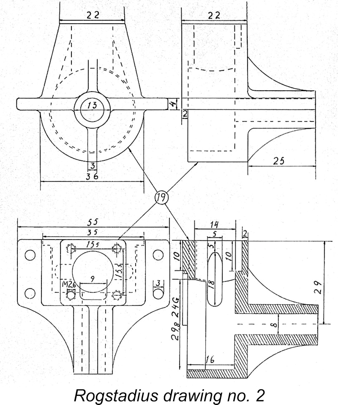
The crankcase of this engine was cast by Wedaverken in Södertälje. Ivan had a few castings made at a cost of 5 SEK(~$1) each, which he thought was a little expensive. He sold a couple of these crankcases to other interested persons. A total of three of these "American" engines were built in Sweden to Ivan's knowledge, and Ivan still owned the one that he built himself. He didn’t know where the others were. Ivan's spark ignition engine was successfully run once when it was newly completed, and after that it had never been started.
No, not as far as Ivan knew. The name applied solely to the published plans as far as he was aware.
Not being an aeromodeller himself, Ivan wasn’t in a position to answer this question. However, his published plans must certainly have exerted some influence.
In December 1943 and January 1944, months after Ivan’s original prototype had been completed and flight-tested.
No.
No, he published them and then gave the originals to somebody from Nyköping or possibly Linköping. Ivan didn’t remember which – at the time of the interview, it was 65 years ago, after all! He didn’t claim the engine as his design, freely admitting that it was a straight Dyno copy to which he had no design rights. Hence the design was not his to sell. Summary Having set out the information provided by Ivan during this November 2009 interview with Lars Gustafsson, it may be helpful to summarize the Rogstadius story as related by Ivan himself.
2) Using this engine as his pattern, Ivan prepared construction drawings in the winter of 1942/43. The prototype 2.04 cc engine constructed from these plans was flight-tested in the summer of 1943 in a model built by Gösta Hellström. This was the first successful combination of an aircraft and diesel engine which were both constructed in Sweden. An article on the flight tests was published in the July 1943 issue of the magazine “Svensk Flygtidning” (the Swedish equivalent of “Aeromodeller” or “Model Airplane News”). 3) The plans and associated construction details of the engine were subsequently published in the December 1943 and January 1944 issues of “Teknik för Alla” Shortly after their appearance in “Teknik för Alla”, these drawings and the construction details also appeared in “Hobby-Boken”, resulting in very wide coverage given the times. This was the trigger for the flood of Scandinavian Dyno clones, of which the previously mentioned Mikro diesel from nearby Denmark was one. 4) Following their publication, Ivan gave the original drawings to an individual whose name he had forgotten. He had no knowledge of any subsequent use which may have been made of these plans.
6) Ivan himself was a model engineer, not an aeromodeller. His interest was in learning how an engine worked, how it was constructed and how others could duplicate it. 7) Ivan later worked for Ericsson with fibre optic cables, actually filing a patent in 1982 on a method for obtaining an accurate concentric fastening of an optical fibre in a connector. 8) The constructor of the 4 mm bore engine mentioned by Ivan was Harry Fjellström, whose remarkable story has been related elsewhere on this website. Harry’s engines survive in the Harry Fjellström collection at the Tekniska Museet (Technical Museum) in Stockholm, where they may be examined today by appointment. 9) Lars Gustafsson's encounter with Ivan was very timely, since Ivan passed away less than 3 years later on September 12th, 2012 at the grand old age of 97 years. Thanks to Lars's efforts, he was one eyewitness to model engine history who didn't slip away without leaving us with his story! _________________________ For completeness, it seems worthwhile for me to reproduce the two main published articles to which reference was made above. I’m deeply indebted to my good mate Lars Gustafsson for his time spent translating these articles into English. The first of these articles deals with the flight-testing of the first-ever model aircraft and diesel engine combination which were both entirely of Swedish origin. This account appeared in the magazine "Svensk Flygtidning", volume 5, issue 7, of July, 1943. Interestingly enough, both the model and engine used in these test flights still survive today, being on display at the Sveriges Modellflyg Museum (Swedish Model Aviation Museum) which is housed with the famous Autoseum in Simrishamn, Sweden. The First All-Swedish Diesel-powered Model Airplane built by Gösta Hellström Not long ago, the first all-Swedish diesel-powered model took to the air above the Skarpnäck airfield. Svensk Flygtidning (SFT) here provides a firsthand report of this landmark occasion.
The idea of building a small model equipped with a diesel engine did not come about by chance. It was born quite a while ago and originated with the Stockholm model builder and highly-praised SFT employee Gösta Hellström. The idea took shape over a long period, but despite much encouragement it did not come to fruition immediately. It is true that some prototypes of the model were made, but the big snag continued to be the necessary small diesel engine. How to get such a thing? A few model diesel engines had found their way into our country, but they had of course been sold instantly and there were no new engines to be found.
Eventually Hellström’s work was rewarded. Through the editor of a model magazine (presumably Gunnar Fahlnäs of “Teknik för Alla” - Ed.), Hellström established contact with another model hobby man - an expert in everything concerning model engines and a winner in numerous model engineering exhibitions. His name was Ivan Rogstadius and he too had been thinking for some time about making an all-Swedish diesel engine. The outcome was inevitable! The two model builders put their heads together. Hellström contributed his expert knowledge in the aeromodelling area and Rogstadius contributed his technical knowledge in the engine domain. Thus there was every reason to expect great things............... It took a long time to make the engine. There were many obstacles to overcome, but despite Rogstadius being called up for a period of military service, the little idea of a short time ago began to grow and, as mentioned earlier, finally reached fruition. Unfortunately, not many people were there to see its culmination, because the two model builders went out in secrecy on a Sunday morning to test the model. For the first flights, they used the old American method for testing engine-powered model airplanes. They simply attached a 200 ft piece of hemp cord to the model to keep it from flying too far away, because they were both fully convinced that flying was about to take place! Despite the weight of the string and the drag that it caused, the plane flew fairly well. However, Hellström had not yet been able to get the center of gravity right, so he had to wind a lot of string around the rear part of the fuselage and bind a 1/4 inch drill into the string to get the model properly balanced.
After that first Sunday, there was not much to do but to repair the model, add some more trim weights and finally repair the nose section. Then they were off again for more testing, and this time they achieved results that they hardly could have dreamt of. The tether cord was omitted and the model was launched with a limited amount of fuel in the tank. The first take-offs were not so successful, but later they got the model to take off well, after which it flew in steep upward spirals to an altitude of about 70 ft. However, the glide was bad because the model stalled on its way down.
Hellström and Rogstadius immediately got their bicycle wheels turning and went looking for the plane. After entering the forest, they kept contact with each other through whistle signals and after about half an hour their efforts were crowned with success. An airman came up on his bicycle and asked if they were searching for the model airplane that he had just found. It seems unnecessary to describe the expressions of joy that resulted......... In this page we reproduce in print some pictures which show the little diesel model plane and its two designers. At the same time, we can announce that a detailed drawing and description of this first all- Swedish diesel model airplane will be published in an upcoming issue of SFT. ______________________ The second article to be reproduced here is that which appeared in the December 1943 and January 1944 issues of “Teknik för Alla” along with construction plans for the engine. It was the prototype engine constructed to check these plans which powered Gösta Hellström’s model featured in the earlier article reproduced above. Here comes the miniature-DIESEL Ivan Rogstadius Presents His Swedish-Built Engine This type of engine surpasses the common petrol engines of equal size when it comes to power, straight-forward design and reliable running. No preheating is needed in order to start it up. The high compression ratio alone suffices for ignition. Kerosene, petrol, ether, lubricating oil and paraffin oil are used in the fuel. The engine has extremely low fuel consumption. In order to achieve a good result, the construction of this engine must be carried out to the highest level of precision. The various components are:
The piston, part 14, and the contra piston, part 11, are turned and finished in one piece. They are held together by a piece that is 5 mm long and has a diameter of 4 mm which is left when turning.
The cylinder head, part 3, is turned from aluminum, beginning with the inner diameter 15 mm, in which a thread is cut, M16X1. After that, the cooling fins on the outside are turned. A dowel should be made and the head threaded on for the final turning job. The intermediate piece, part 7, is made from aluminum. Make a hole in the work piece, 14 mm inner diameter and plane it. Mount the piece onto a 14 mm dowel for turning to get the height 17 mm and then do the rest of the work to shape the intermediate piece. The T-cut which can be seen inside across the hole for the carburetor connects the two 4 mm holes in the cylinder with the carburetor. The compression adjusting lever, part 1, is turned from steel. Part 2 is a spring that prevents the compression adjusting lever from changing position during running. It is made of steel sheet which is hardened and tempered to a bluish grey color, dipped in oil and heated once again to burn the oil off, a procedure that is repeated approximately five times in order to give the spring the required strength. It should be possible to work on it with a file after the hardening, otherwise it will snap when it is mounted. Part 4, the carburetor needle, is turned from steel and the head drilled out in order to reduce weight. Part 5, the cylinder mounting studs, are made from stainless steel, chrome nickel steel or screw iron, which is case hardened. Heavy bicycle spokes can also be used as stud material.
Part 8, carburetor mounting screw, is turned from steel and blue tempered. Part 9, crankcase cover, is turned from aluminum. On the back side, two holes are drilled to fit a key with two pins in it. A hole is drilled and a thread is cut for mounting the fuel tank. Part 10, the compression screw, is turned from steel and drilled out so that the compression adjusting lever can be threaded in from any one of four directions, after which it is hardened and tempered blue. Part 12, cylinder retaining nuts, are made from steel or iron which is case-hardened. Part 15, gudgeon pin, is turned from steel which is then hardened. A couple of brass studs are driven in to the ends to prevent damage to the cylinder bore. The gudgeon pin fit in the piston should be rather tight, but looser in the connecting rod. If the fit in the piston is too tight, the piston will become oval and stick in the barrel. Part 16, connecting rod, is made from steel, hardened and tempered. The lower part is tempered blue and the bushing (which should be made of Nika or phosphor bronze) is pressed in. Part 17, crankshaft, is turned from steel. A 3/10 mm allowance is added for grinding. The web for the crank pin is blue-tempered and the hardened steel crankpin is pressed in. The crank shaft is then ground to size. Part 18, main bearing bushing, is turned from Nika or phosphor bronze and press-fitted into the crank case. Part 20, propeller hub, is turned from steel and fitted to the tapered portion of the crank shaft. After hardening, a propeller driving pin is pressed into the hub. Part 21, spinner, is turned from aluminum, and hollowed out to get it as light as possible. The fuel tank, which in this case is made from a bicycle rear reflector, can be made according to your personal preference and ingenuity. The propeller is made from oak, ash or white beech. The recommended diameter is 270 mm, with recommended blade width being 25 mm at the widest point and the thickness at the hub being 13 mm. Be careful to ensure that all threads fit properly without any play. If all sealing surfaces are carefully machined, no gaskets are needed. If necessary, thin paper can be used for gaskets. Test running of the engine The fuel consists of 60% kerosene, gasoline or petroleum spirit, 15% paraffin oil, 15% auto oil and 10% ether. The tank is filled with fuel, the needle valve is opened a couple of turns and the crankshaft is turned over a couple of times while the air inlet is covered with a finger. After this, the engine is started. If it does not fire, the compression setting is increased until it starts. Be careful at the outset and make only short test runs. When the engine is broken in, the paraffin oil and the engine oil can be reduced somewhat. This engine reaches 7,500 rpm and yields 1/10 HP. Conclusion I hope that you’ve enjoyed making the acquaintance of one of the most significant, and certainly the most durable, individuals associated with the early propagation of the model diesel. Ivan Rogstadius was a pivotal figure who ranks with Jan David-Andersen and Thorning Bensen in term of his role in establishing the model diesel engine in the Scandinavian countries. ___________________ Article © Adrian C. Duncan, Coquitlam, British Columbia, Canada First published January 2010 on MEN This revised and expanded edition published here June 2026
|
 I’ll begin this article by confessing that I retain an unashamed nostalgia for what I recall as the Golden Age of aeromodelling and the now-elderly model engines which powered the models of that era, especially those lovely, smelly, oily diesels which served us so well. I can still close my eyes and smell the fresh-cut grass of the flying field mingled with the (to me) heady aroma of diesel exhaust carried on the warm summer breeze! Many present-day fliers find this aroma objectionable – to me, it’s synonymous with fun, triggering a host of happy memories!!
 But that’s precisely my point – it was the overcoming of such difficulties that gave so much satisfaction to yesterday’s modellers like myself. We sought out such challenges and took pride in working to overcome them – the exact opposite of today’s prevailing mindset, which appears to me to emphasize the avoidance of challenges. Back then, everything was either new or evolving, constantly posing new challenges which were a joy to meet and overcome! The greater the challenge, the greater the satisfaction to be gained from overcoming it!
  In no field was this more true than in that of model engine design, development and operation. The design, construction, preparation, handling and successful application of those early engines involved the acquisition of hard-earned skills in which model engineers and power modellers alike took great pride and from which they derived immense satisfaction.
 The development of this article had its genesis early in the present millenium in a folder of information sent by the late
 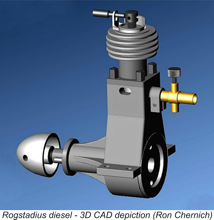 It was apparent that this article detailed a Swedish model diesel engine intended for home construction, probably circa 1944, clearly based on the Swiss Klemenz-Schenk Dyno 2.04 cc diesel of 1941. The
 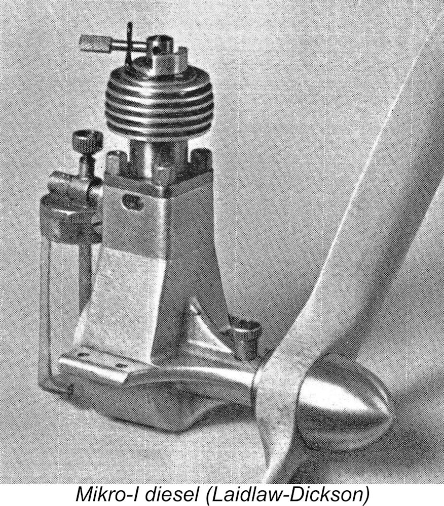 The first responses from the late Bert Streigler and myself both remarked on the engine’s extremely close similarity both to the Dyno and the
 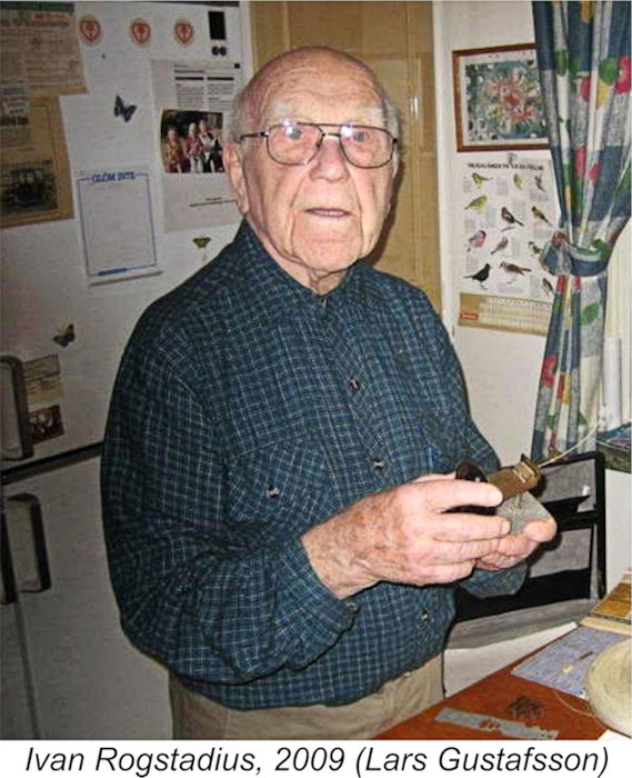 n 1942 the chief editor of “Teknik för Alla”, Gunnar Fahlnäs, had somehow come into possession of a Swiss Dyno I engine. He asked Ivan (then 27 years old) to make drawings using his Dyno engine as a pattern, the intent being to publish the drawings in the magazine for the use of home constructors. Ivan stated that he made the drawings in the winter of 1942/43 without changing any aspects of the original Dyno design. He then built his first engine for the purpose of testing its utility.
 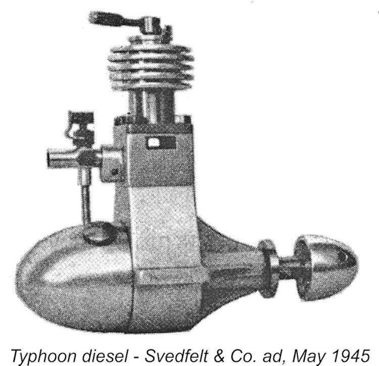 No, Ivan had no contact at all with the Johansson brothers and he didn't know anything about the brothers or their diesels.
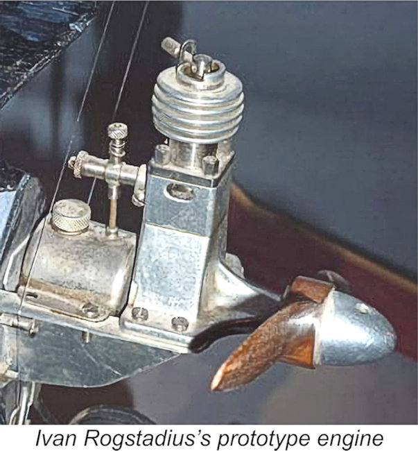 No, Ivan didn't initiate any series production himself. He did recall receiving a question from the USA asking if he could supply engines to that country. Ivan's answer to this inquiry was negative - he never had any aspirations about going into series production.
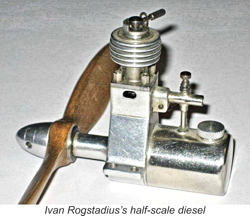 One of the two engines that Ivan built was given to Ivan’s close friend Gösta Hellström, who built the free flight model which they flew together at Skarpnäck in the summer of 1943 to test Ivan’s prototype engine. He sold the other engine to a couple of boys in Stockholm.
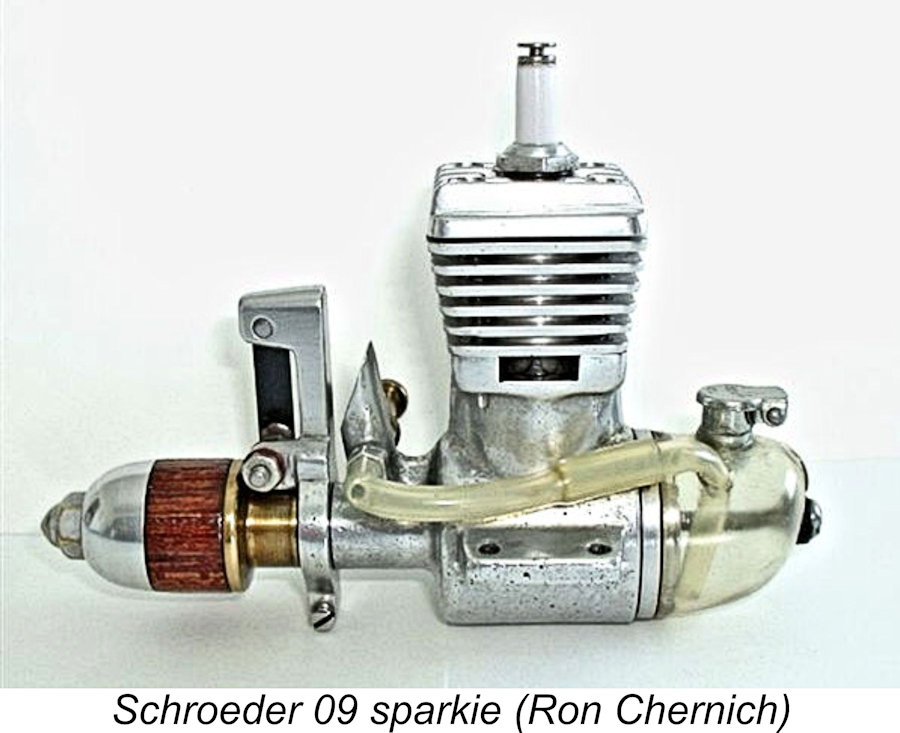
 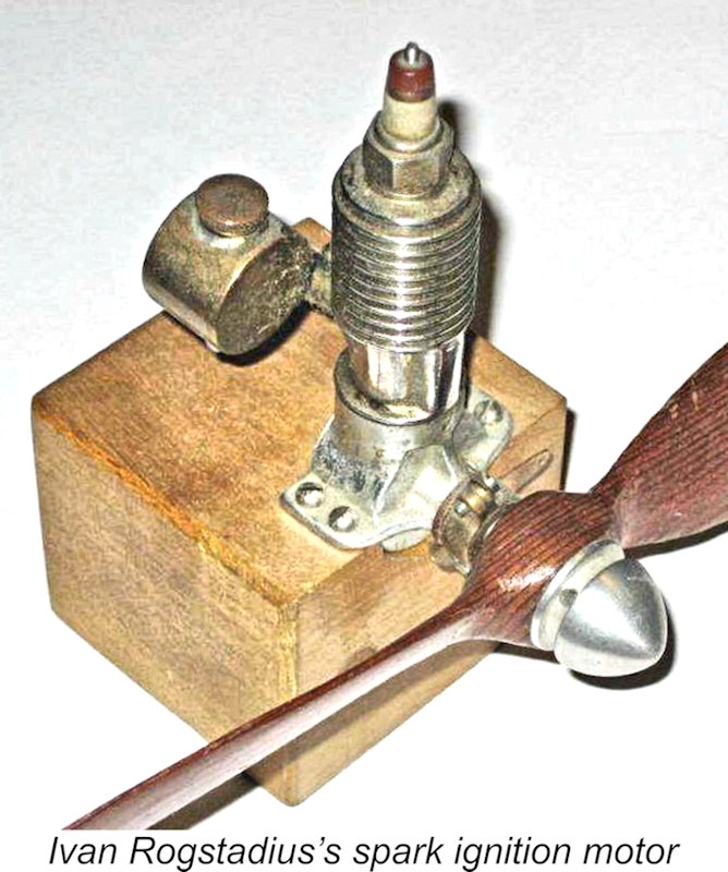 Ivan had no engines, parts or documents for sale. At the time of the interview, he still had the half-scale engine as well as another self-constructed engine, a spark ignition model which he built from a drawing in an American magazine - Ivan didn’t remember which one. This engine was built well before he made the Dyno diesel copy, during the very early 1940’s. Ivan even made the spark plug for this engine. It appears to have been based on the original Ohlsson plans.
 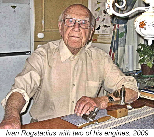 The first Dyno in Sweden was almost certainly the Swiss example mentioned earlier that Ivan took as the basis for his drawings. Ivan didn’t know precisely when or how that engine came to Sweden across war-torn Europe, but it was certainly in the country in the latter part of 1942. Ivan developed his drawings before attempting any construction, and his first Dyno copy was constructed in the early summer of 1943 before the plans were published, using his plans as a guide. As far as he knew, it was the first one built in Sweden.
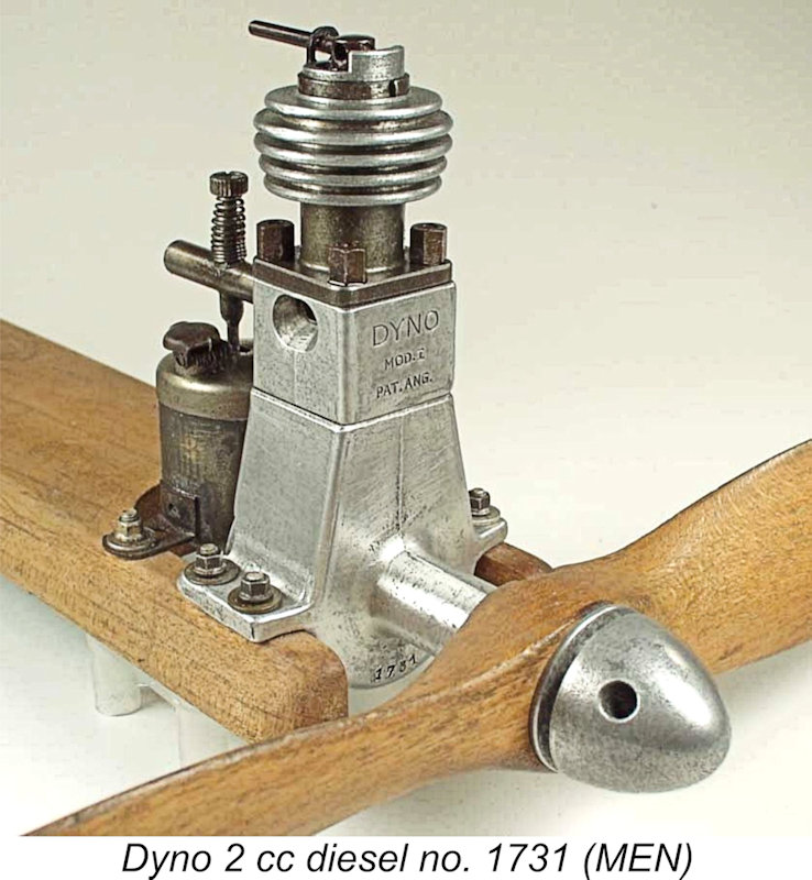 1) In 1942, the editor of “Teknik för Alla” somehow managed to get hold of an original 2 cc Swiss Dyno. This would have been no small accomplishment given the state of war-torn Europe at the time! He asked Ivan to prepare plans to allow the home construction of additional examples.
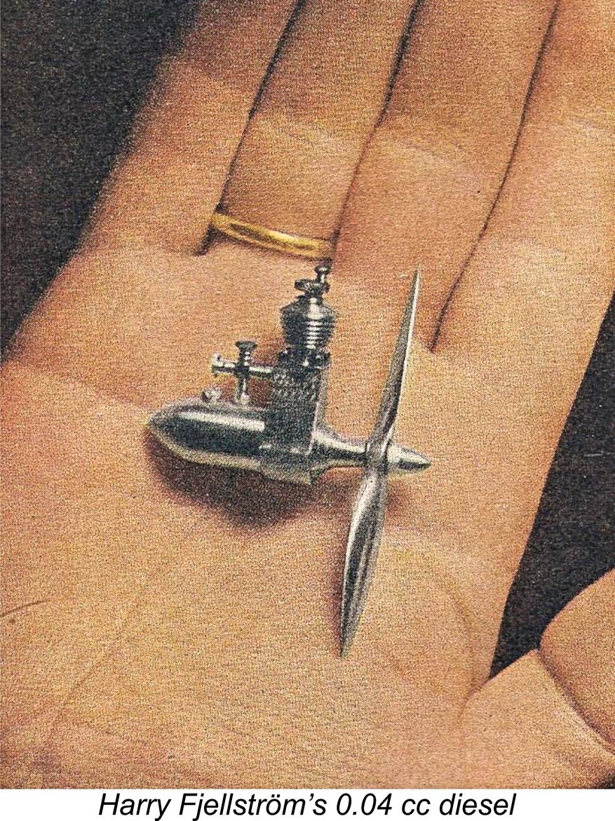 5) Ivan had nothing to do with either the Swedish Komet, R-H and Typhoon engines or the Danish Mikro, although he agreed that they may well have been based on his published drawings which were freely accessible for anyone to use. As far as he knew, there never was an engine marketed with his name attached. Ivan was not at all troubled by this; he made the drawings and wrote the article purely to enable others to build their own model diesel engines. He never claimed that the design was anything but a Dyno copy.
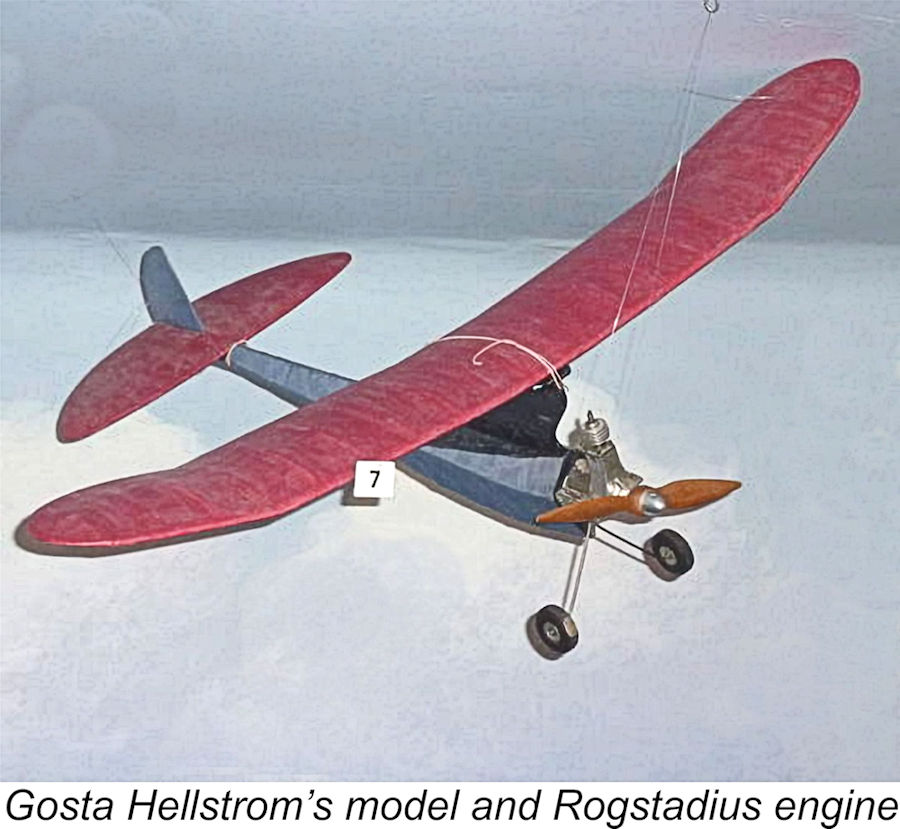 During the last little while, big things have occurred in the sphere of model aircraft flying. Some time ago, the first all-Swedish diesel-powered model aircraft had an opportunity to try its wings in the thermals above the small Skarpnäck airfield near Stockholm. It was something of a sensation when two young model flying enthusiasts from Stockholm took to their bicycles and went to Skarpnäck in order to test their brand-new diesel-powered model airplane - the first all-Swedish example of its kind. If one could speak of an epochal event in the context of our relatively new aeromodelling hobby, such a word would certainly be appropriate to this situation!
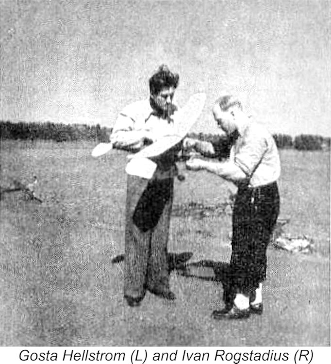 Difficulties exist merely to be overcome, and Gösta Hellström happily started out on his model - a fine little aircraft in the smallest class. It has all the characteristics that typify a Hellström model. The shape of the model is a little unorthodox, but it has beautiful lines and it is so meticulously built that you can´t find the words to express your admiration.
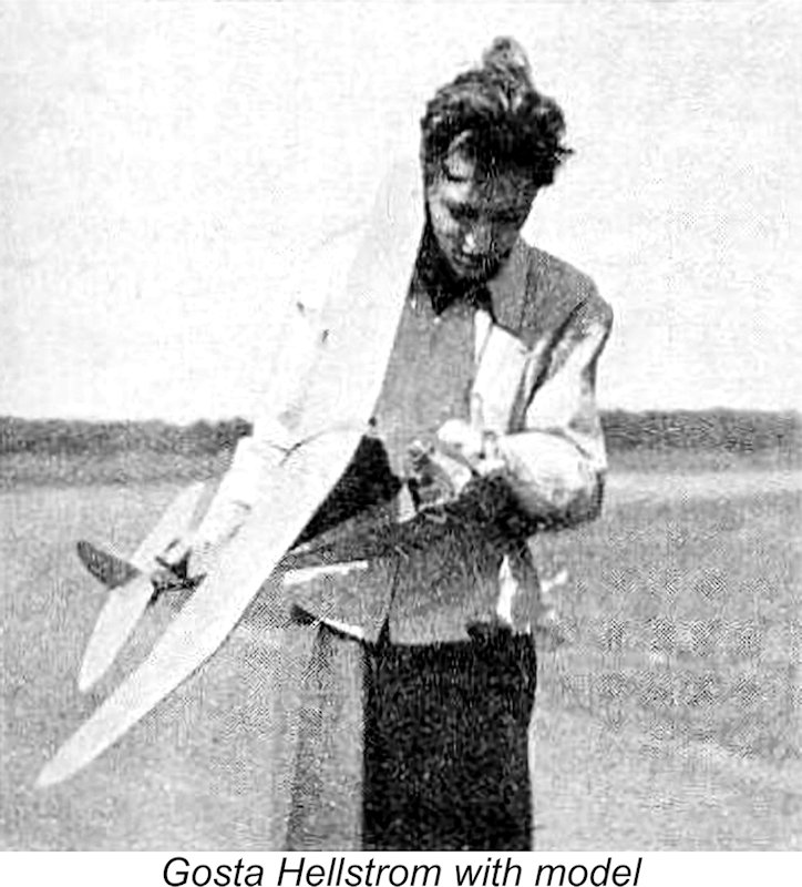 During the first test hops, they couldn’t avoid breaking a number of propellers. Time and again, pieces were torn off during less-graceful landings and the model eventually flew with a prop that was worn down to about a two-inch radius, but still it flew well...……It managed to take off from the ground after a fairly short run - something extraordinary to see!
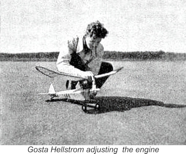 Before the next start, the trim weight was moved forward and after that the flying really started! After a 5 ft ground roll, the plane rose off the ground, taking smoothly to the air and climbing in a very steep spiral to an altitude of about 250 ft during 30 seconds of engine run, after which the glide started. And what a glide! The plane moved gradually towards the border of the field and soon it was outside the field limits and far away over a big forest.
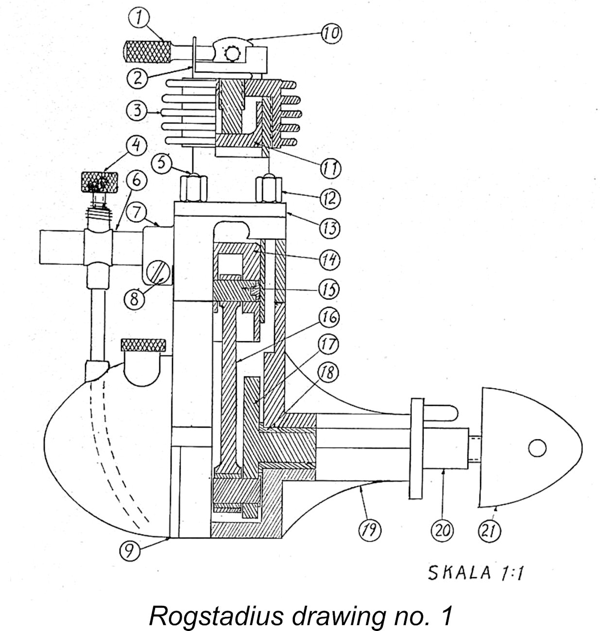
 When the crankcase is finished, you should continue with the cylinder, part 13, which is turned from a steel such as Fagersta 14B4, which is particularly suitable because it does not distort so much in the hardening process. When turning the cylinder, a 3/10 mm allowance for grinding is added where the triangles in the drawing indicate that grinding should be done. Great care should be taken when forming the ports, especially the height measurements. The exhaust ports, which are 7X4 mm, are located one on each side of the engine. The two ports that are 4X2.5 mm transfer the gas mixture from the crankcase to the upper part of the cylinder. Two more ports, 4 mm in diameter, pass the gas mixture from the carburetor to the crankcase and must therefore be located on the carburetor side of the engine.
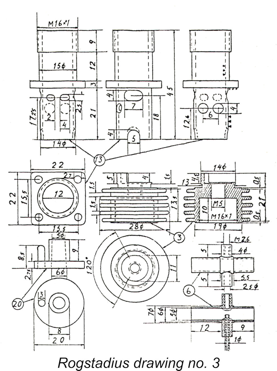 Due to the long stroke of this engine, a couple of cutaways measuring 5X4 mm have to be made in the lower edge of the cylinder to provide clearance for the connecting rod. When filing these cutaways, follow the dotted line on the inside. The cylinder is then hardened and tempered. For the grinding of the cylinder, a hollow metal dowel is turned and a M16X1 mm thread is cut internally. The cylinder is screwed into this dowel, which can then be clamped in the lathe chuck for grinding. Due to the very thin walls of the cylinder, it cannot be clamped directly in the chuck, because then it would not be round after the grinding. The tolerance for the inside grinding is 5/1000 mm, and therefore it must be done with utmost care, especially above the exhaust ports.
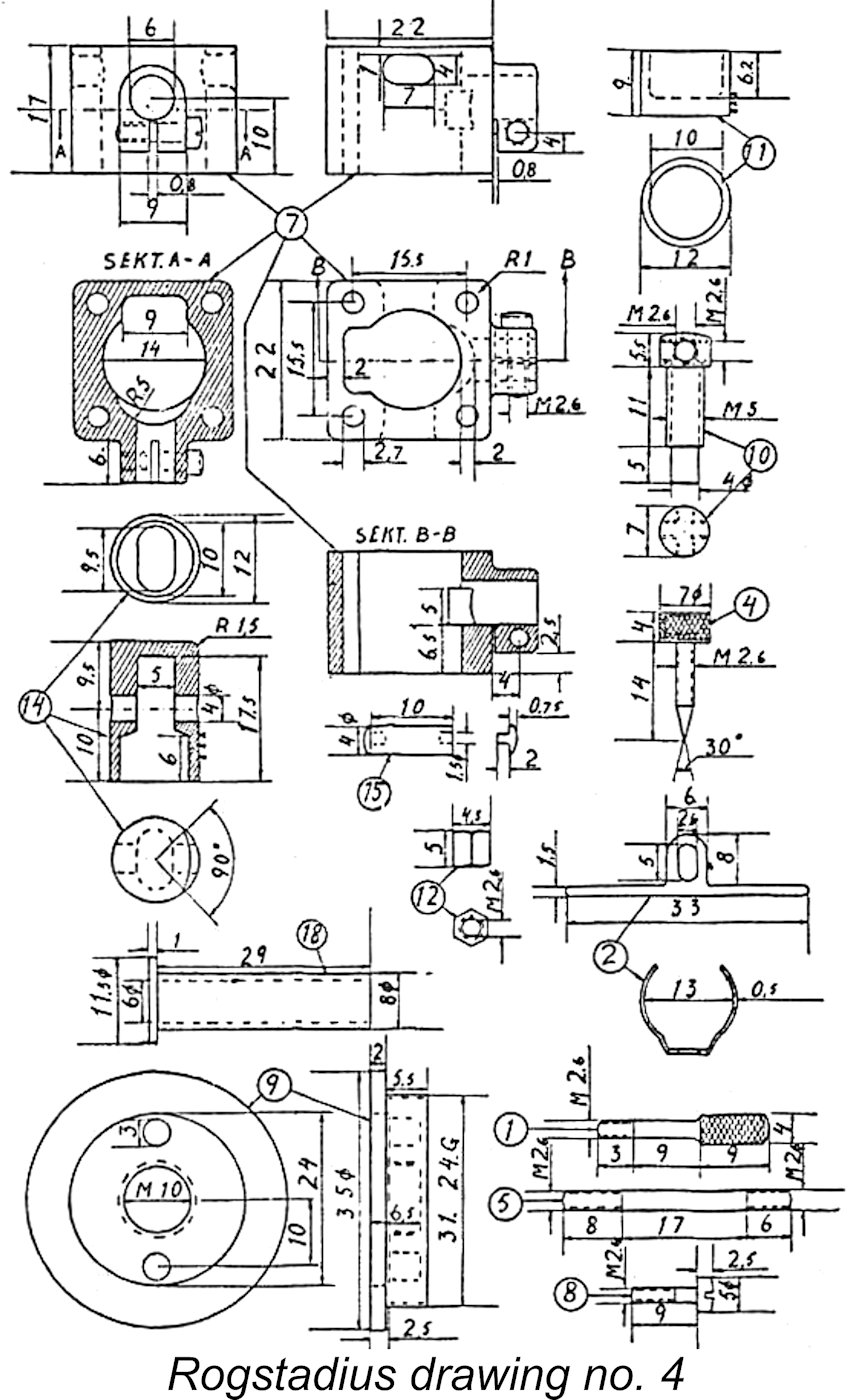
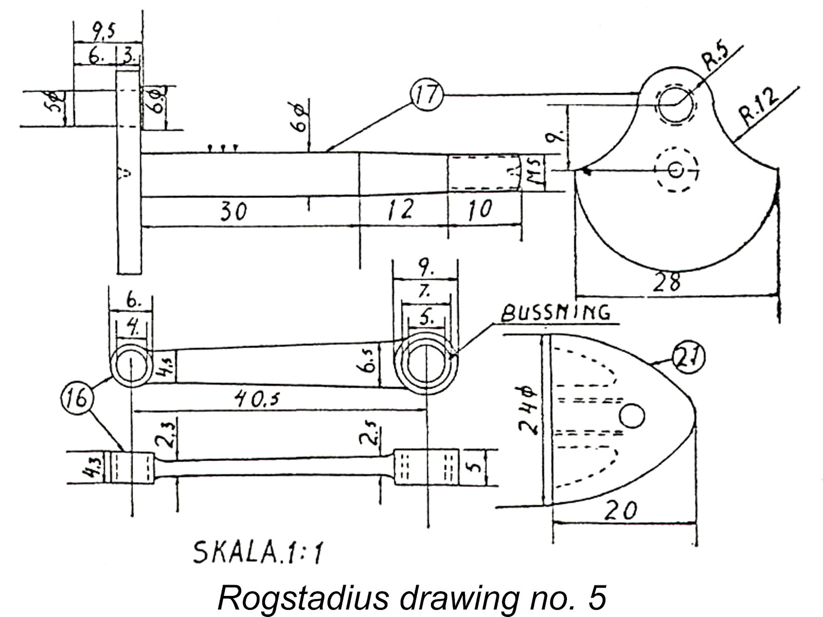 The carburetor body, part 6, is made of brass. Firstly, the horizontal and vertical tubes are made. A hole is drilled in the vertical tube to take the horizontal tube, which is installed and hard-soldered. The portion of the vertical tube that is inside the horizontal tube is then drilled out. Threads for the needle valve are cut in the carburetor, which then is nickel plated. A coil spring is wound and added to the carburetor so the needle valve doesnt turn too easily. The seating for the fuel needle is shaped with a pointed spiral drill.
| |