
|
|
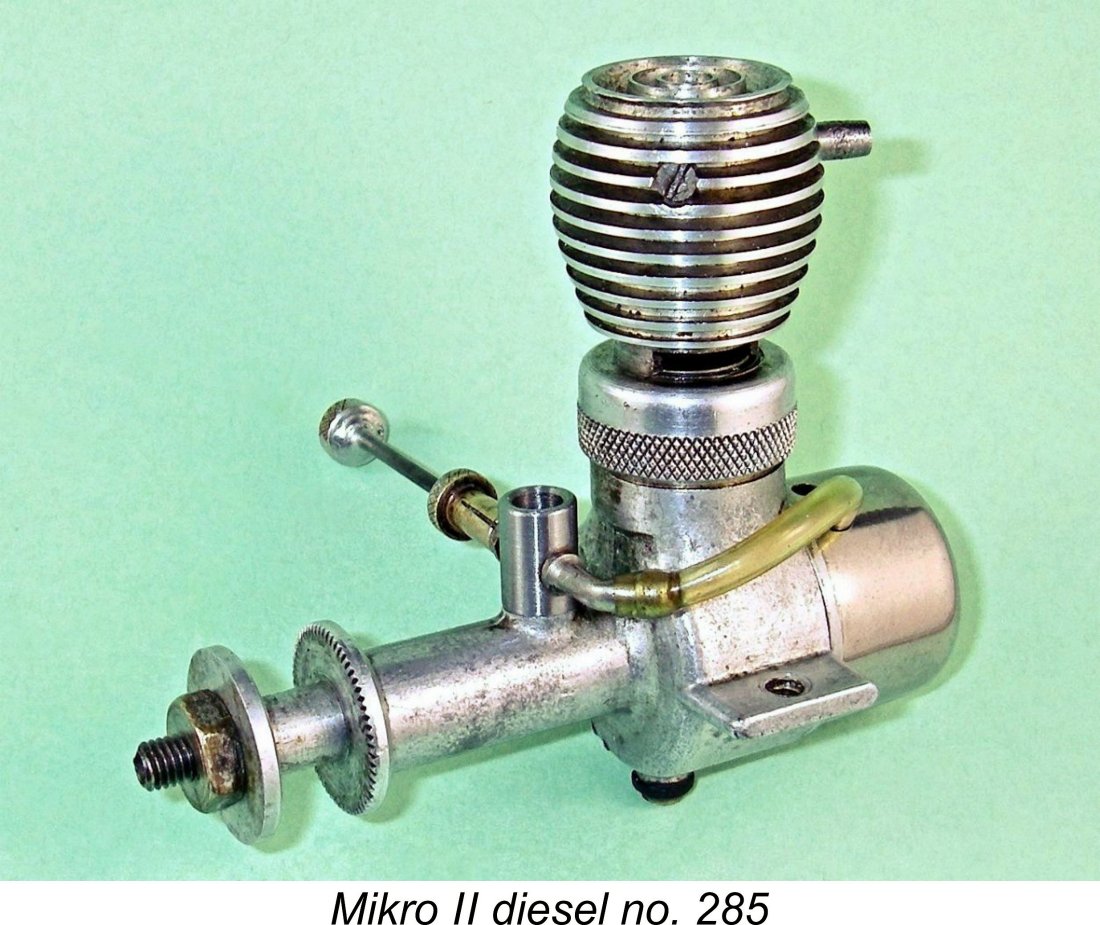
The Mikro II Diesel
More recently, Luis was good enough to pass along a nice boxed example of one of the rarest Mikro models, the Mikro II diesel of 2 cc displacement. This has put me in the position of being able to present an actual bench test of that rather rare engine, amounting in my book to an obligation to do so. Model engines of this rarity should be shared to the extent possible! That’s one of the purposes of this website ………. I do not intend to repeat my earlier comments regarding the genesis of the Mikro range and its place in the overall Danish model engine manufacturing picture - interested readers are referred to the earlier articles cited above. I will however summarize the background to the introduction of the Mikro II diesel itself. In doing so, I will inevitably repeat myself to some degree. However, it will save interested readers some hunting about if I reprise that material here. Those already in the know are cordially invited to skip past the next section of this article. Background
The idea of producing a model diesel was apparently suggested to Nielsen by one of his employees, who showed up at work one day in 1944 with a Swiss Dyno diesel which he had somehow obtained despite the ongoing German occupation. Like most of the model diesels which appeared at this time outside France, which developed its own style very early on, the original Mikro model (generally referred to as the Mikro I) turned out to be basically another Dyno clone which evidently owed much to the Dyno-based plans published in Sweden by Ivan Rogstadius in early 1944. The Mikro I appears to have come onto the market in the early part of 1945, quite possibly at a time when the German occupation forces were still in place. It was initially advertised in Denmark at a price of Kr. 138. Interestingly enough, the attached 1945 advertisement confirms that members of the Danish Modeller's Union (Dansk Modeller's Union - DMU) were offered a 15% rebate.
The Mikro I was an exaggeratedly long-stroke sideport design, having bore and stroke measurements of 12 mm and 17.5 mm respectively for a displacement of 1.98 cc. The engine weighed in at a fairly porky 220 gm (7.76 ounces) and developed a claimed 0.10 BHP @ 7,500 RPM - a reasonably credible claim. Most of these engines were apparently used in the 2 cc tether car racing class which was then very popular in Denmark. A very neat feature of the Mikro I design was the wire clip which encircled the top of the cylinder head and had a vertical extension which engaged with the compression screw lever. This was a very simple and effective means of discouraging the comp screw from running back during operation. It was adopted more or less simultaneously by the designer of the DELMO 2.65 cc diesel from Paris, France. The cylinder head also featured an integrally-machined upstanding stop which limited the range of movement of the comp screw.
It appears that Kai Nielsen did not pursue the manufacture of the Mikro I diesel with any great vigour, probably treating model engine production as a sideline to be used to pick up otherwise-unused workshop capacity and keep his empoyees busy. The initial selling price of Kr. 138 was reduced to Kr. 98 in 1946, presumaby to meet the lower-priced competition then appearing from other Danish makers such as Thorning Bensen. Only around 250 examples of the original sideport Mikro I model seemingly ended up being produced over a period of perhaps 3 years or so. The periodic production of small batches is implied. By 1948, sideport engines were beginning to be viewed as anachronisms, hence being rapidly replaced by rotary valve engines which were inherently capable of higher operating speeds. Nielsen could not help becoming aware of this trend. In 1948, he decided to act. The result was our main subject here - the Mikro II diesel. The Mikro II Diesel Described
The Mikro II was built up around a completely new crankcase produced by gravity die-casting. A drop-in hardened steel cylinder was employed. This was secured to the crankcase by an internally-threaded collar very much along the lines of the “dog collar” used by the K Model Engineering Co. in England as well as by Giancarlo Pinotti in Sweden. The collar engaged with an external thread cut around the top of the crankcase casting. It bore on the cylinder installation flange to hold the cylinder in place.
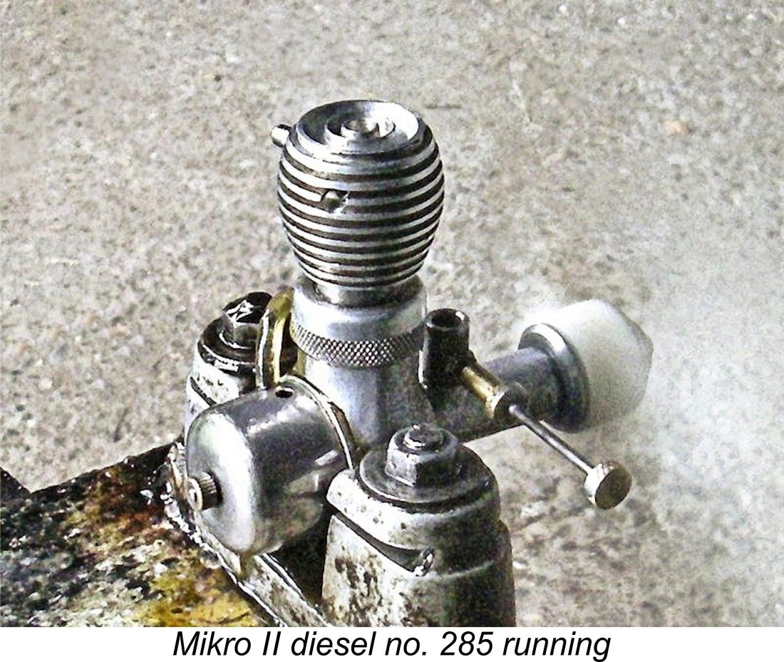
In the case of the Mikro, the really unusual aspect of this arrangement was to be found in the means of providing a purchase for the use of the operator in making compression adjustments. No penny-slots here! Three radially-oriented tapped holes were formed near the top of the cooing jacket at a uniform 120 degree spacing around the jacket circumference. Two of these were plugged by short brass machine screws, while the third was occupied by a threaded tommy bar which provided a secure grip to facilitate compression adjustments. So why three radial holes - wouldn’t just one suffice? Well, here’s the really unusual feature of this arrangement! The screw-in tommy bar penetrated well into the upper bore of the cooling jacket, extending right across the annular space between the inner wall of the jacket and the central boss which acted upon the contra-piston. The cylinder was provided with an upstanding segment at the front which protruded into the annular space and limited the available angular movement of the jacket when the tommy bar was fitted. The attached illustrations should make this clear.
Simple! If more compression was genuinely needed than was allowed by the set-up as it stood, one simply unscrewed the tommy bar, removed the brass machine screw to the right of the tommy bar’s former hole and re-installed the machine screw in the tommy bar’s vacated hole. One then screwed the tommy bar into the hole formerly occupied by the machine screw, 120 degrees to the right. The jacket could now be screwed down by an additional 120 degrees before the tommy bar met the stop and further downward movement was prevented. Of course, if a sufficiently low compression setting could not be secured, one simply reversed this procedure by moving the tommy bar in the other direction around the head.
Moving on downwards, the engine featured cross-flow loop scavenging. A single rectangular exhaust port of generous width was located at one side, with a single transfer port on the other. The transfer port was supplied by a rather small bypass passage formed in the inner wall of the upper crankcase. The presence of the cylinder location flange below the exhaust port forced the transfer port to be positioned well below the exhaust. Because of this, and also due to the fact that an upstanding piston baffle cannot readily be provided in a simple diesel like this one, a step was cut into the crown of the hardened steel piston at the transfer location to accommodate the necessarily low position of the transfer port and also provide some directional control of the incoming mixture. This was very much along the lines of the stepped pistons used in England by E.D. and Mills Bros.
The use of a stepped piston obviously required that the cylinder be retained in the correct orientation to align the piston step with the bypass flute, placing the exhaust on the left hand side of the engine (looking forward in the direction of flight). This orientation was ensured through the use of a set-screw which engaged with a small cutaway at the base of the cylinder wall to prevent it from turning in the case. This screw may be seen in the accompanying images. I chose not to disturb this assembly, hence being unable to supply further details.
At the front, the relatively long main bearing housing was completely unbraced - a potential area of weakness if the engine was used in model aero service. It might not do well in a hard crash! A light alloy prop driver was used in conjunction with a conventional prop nut and washer. The intake venturi was a separate screw-in item which threaded into a 5 mm tapped hole on the top of the main bearing housing. The spraybar had a neatly curved fuel pick-up end to facilitate the routing of the fuel line to the tank - a nice touch. A split thimble Interestingly enough, the crankshaft rotary valve in this example is timed for reverse rotation (clockwise viewed from the front). A surprising number of European engines of this era were timed for such an operating direction - it seems to have been quite popular. I have no information regarding whether or not all examples of this engine were timed in this way. Induction timing was every bit as conservative as the cylinder port timing. The induction cycle opened at 45 degrees after bottom dead centre. Fair enough, but the port closed at top dead centre exactly! This is certainly not a recipe for high performance! The induction period is only 135 degrees - certainly longer than could be accommodated using sideport induction, but that ridiculously early closure would undo much of any gain.
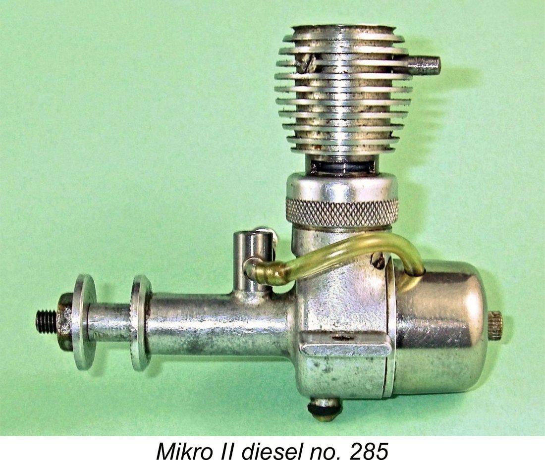
The final touch was the provision of a crankcase drain plug at the base of the main casting. This was a somewhat anachronistic feature which was going out of fashion by this time. I suppose it might have its uses on occasion, but those occasions would be few and far between if the engine was operated properly. Like other Mikro engines, the Mikro II units all bore serial numbers which were neatly stamped onto the underside of the main bearing housing. My illustrated example bears the number 285, seemingly confirming that at least that many were manufactured. Production History
At the time, tether car racing remained very popular in Denmark, which explains why the engine was clearly seen by its designers as being primarily a car unit. It was doubtless this perception which led to its being timed for reverse operation to take advantage of the torque effect in helping the car to run around its circular track. It probably also explains the very long needle valve, the provision of only two mounting holes in the beam mounting lugs (both of which were tapped) and also the use of an unbraced main bearing housing. The engines were supplied in a sturdy cardboard box which lacked any kind of label. The only external indication of the contents was the neatly handwritten designation "Mikro diesel II" which appeared in blue ink on the box lid.
Instead, the statement was made that all engines were test-run at the factory and were supplied with the compression and fuel needle set correctly. The expectation was obviously that owners would leave well alone and just follow the very clear starting directions! Show me an owner who could resist the temptation to "fiddle" with his new engine ....... I never could! Also, it's impossible to believe that the engines were indeed supplied with the needle set correctly - to fit the engine into the box, the needle would have to be removed. An interesting comment included in the instruction sheet was a statement that the makers could supply a plan for an easy-to-build model suitable for the engine at a price of Kr. 2.50. I have no information on the size and type of model to which this referred. Reference is also made to a pipette which was apparently supplied with the engine to facilitate fuelling. This is missing from my boxed example. The Mikro II was reportedly designed by an engineering colleague of Nielsen's named Henriques. It’s possible that despite whatever other engineering expertise he may have had, Henriques was a relative newcomer to model engine design. Certainly, the Mikro II as originally released exhibited a number of design problems. Although it was very ingenious, the system of compression adjustment left something to be desired in terms of convenience. More problematically, the cylinder wall thickness was very marginal, the consequence being that the cylinder reportedly tended to crack with relatively little provocation.
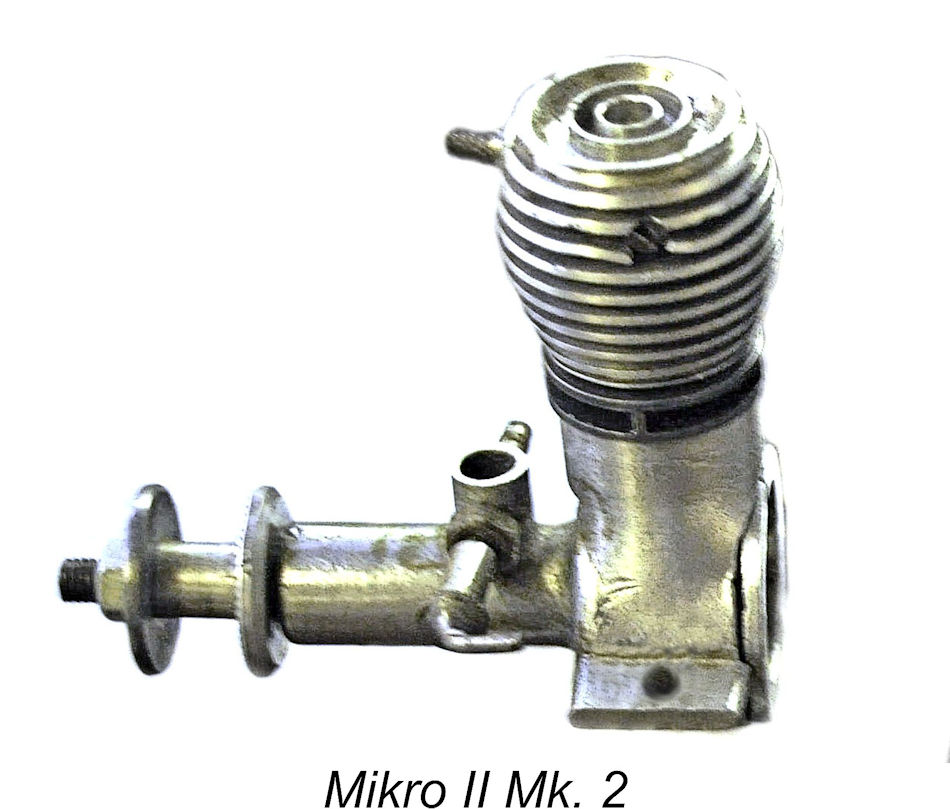
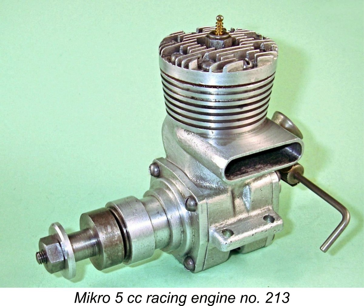
Quite apart from this, the engine signally failed to match the levels of performance then being displayed by other competing models of similar displacement. Design revisions were soon put in hand to address these issues, the result being the release of a significantly improved version of the Mikro II in 1949. This utilized a completely revised screw-in cylinder, replacing the former "dog collar" installation. Moreover, the new cylinder featured conventional radial porting in place of the former cross-flow loop scavenging. These changes overcame the previously-noted cylinder weakness, also improving performance considerably. However, the damage to the engine’s In 1950, after abandoning the Mikro II project, Nielsen introduced a potent-looking Mikro 5 cc racing glow-plug unit. This too was reportedly designed by Nielsen's colleague Henriques. Its design owed much to the various leading American units of the period, particularly the Dooling, although it actually displayed a good deal of quite effective original thinking. However, its reported output of only 0.35 BHP @ 16,000 RPM was not competitive, and Nielsen appears to have abandoned the model engine field entirely after perhaps 500 or so examples of the racing model had been made. The Mikro 5 cc racing glow was actually a far better engine than the published report would suggest, as my own tests have shown. A full review and test of this final Mikro model (engine no. 213) may be found elsewhere on this website. The Mikro II Diesel on Test My example of the Mikro II is a Mk. 1 example bearing the serial number 285. It is one of the earlier variants with the various design issues noted earlier remaining unaddressed. This being the case, I was frankly expecting very little in the way of performance. The engine remains in excellent mechanical condition, although it has clearly seen a certain amount of use in the past. Despite this earlier running, it has a slight "tight spot" in the bore around bottom dead centre - unusual! The rest of the stroke feels fine, with outstanding compression. As mentioned earlier, the original Mikro I sideport model developed a claimed 0.10 BHP @ 7,500 rpm. Its main drawback was that it weighed all of 220 gm (7.76 ounces - a lot of weight for that power output. The question was therefore whether the far lighter Mikro II could at least match the output of its predecessor, thus achieving a superior power-to-weight ratio. In conducting this test I was greatly hampered by the fact that this engine is timed for reverse rotation, forcing me to use pusher props for testing. I would just have to do the best that I could using whatever suitable pusher props were on hand. Fortuitously enough, I had Tornado nylon 8x6 and 9x6 pusher props which I felt would serve very well as test props for shake-down and familiarization runs. I remained mindful of the cylinder cracking issue, hence resolving to keep running time down to the minimum necessary to gain some appreciation of the engine’s performance or lack thereof. The instruction sheet with the Mikro II placed a high emphasis on the avoidance of flooding. Port priming was strongly discouraged. The use of the crankcase drain plug to clear a flooded case was fully described in the instructions. A single choked turn was cited as being all that was required for starting. I had to keep reminding myself to turn the thing backwards while choking!
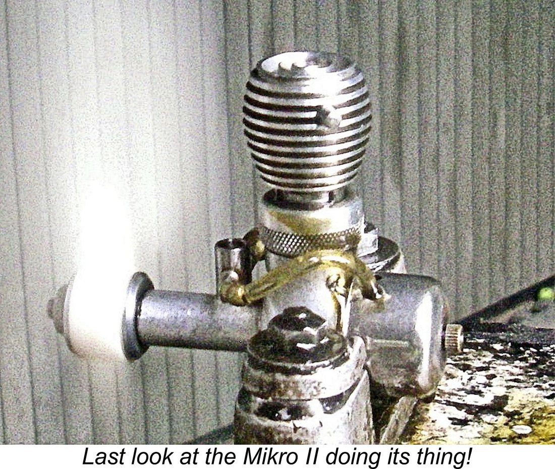
The recommended fuel was a rather odd blend containing 40% ether, 40% oil of an unspecified type and 20% “petroleum”. I’m not sure whether the latter term referred to gasoline or kerosene. I stuck with my usual “old diesel” brew of 35% ether, 35% kerosene and 30% castor oil, with 1% ignition improver added to the overall mix in this instance. Most oldies but goodies run just fine on this brew. Starting a diesel in reverse is a bit weird for a right-handed person like me! You have to set the prop against compression in reverse at “ten past eight” (as seen in the attached image) and then flick downwards really hard with the fingers of your right hand. Having a test subject that starts easily is a real bonus!
Once the correct approach was found and adopted, starting was perfectly straightforward. However, I'm a highly experience diesel user, and even I took a while to get on top of things. A beginner would have found this engine very challenging indeed, especially if he followed the instructions! Once the engine was running, a few characteristics became immediately apparent. The Mikro exhibited a chronic misfire which was very difficult indeed to eliminate. It was possible to achieve smooth mis-free running, but both compression and needle settings had to be spot on - a small amount either way brought back the misfire. That said, the misfire didn't slow the engine down much at all, so the actual settings for best operating speed on a given prop weren't as critical as might be supposed. I quickly discovered another negative aspect of the engine's compression adjustment system. The cooling jacket gets quite hot, making compression adjustment with a hot engine a bit of a pain (literally!). I had to wear my Kevlar glove while However, one positive outcome of this was the finding that the system was very smooth in operation, to the point that the tommy bar wasn't strictly necessary - I found that I could easily make adjustments by gripping the cooling jacket directly with my gloved hand. Once set, both compression and fuel controls held their settings very dependably. As might be expected from the late exhaust port opening, the exhaust note was relatively subdued during operation. Having taken the trouble to establish the perfect miss-free settings, I found that the Mikro would run the tank out very smoothly, seemingly accommodating the change in fuel head very well indeed. Draining the tank took quite a while - I timed one continuous run on a full tank using the 9x6 prop at almost 51/2 minutes! This engine sips its fuel! For free flight applications, a separate tank of far smaller capacity would be required. The next issue to rear its ugly head was that of performance - there simply wasn't much! The Mikro dragged the rather parasitic Tornado nylon 9x6 pusher prop around at a rather lacklustre 5,400 rpm. Not too impressive! A switch to a Tornado nylon 8x6 pusher only got the engine up to 6,000 rpm. The relatively small difference between the two props clearly implies that the Mikro was already beginning to run out of puff at that 6,000 rpm figure. This being the case, and remaining mindful of the reported cylinder cracking tendencies, I decided against pushing the engine any further. The Mikro had had its 20 minutes of fame - that was good enough for me! It's worth observing in passing that the 20 minutes or so of runing that I put on had no perceptible effect upon the previously-mentioned perceptible "tight spot" around bottom dead centre. That's the price that you pay for using a hardened steel piston in a hardened steel cylinder - the tight bits stay tight! I don't have power absorption coefficients for the Tornado nylon pusher props. All that I can say is that if the coefficient for the Tornado 8x6 pusher is the same as that for the tractor version, the indicated output at 6,000 rpm would be of the order of 0.044 BHP. Frankly, I wasn't surprised to find such a low level of performance. The absurdly early closure of the induction cycle, the tiny 3 mm induction passage, the very constricted bypass arrangements and the ultra-short exhaust and transfer periods all combine to dampen any expectations of noteworthy power output. I'd actually expect substantially more from the earlier Dyno-based Mikro I. Conclusion
Even so, the original model as tested above was so significantly deficient in terms of performance and handling (setting aside the structural integrity issue) that it was inevitable that its reputation would have been irreparably damaged by reports of the first examples to enter service. Even a revised model would not have been enough to restore the engine's shattered credibility after a start like that! A lot of the original engines probably ended up being thrown away, partially explaining the engine's extreme rarity today. Having said all of this, I feel privileged to own an example of this very rare unit, warts and all - thanks, Luis! I thoroughly enjoyed the challenge of getting to grips with it and putting it through its paces, such as they were! ______________________________ Article © Adrian C. Duncan, Coquitlam, British Columbia, Canada First published February 2023 Revised April 2023 - details of Mikro II Mk. 2 |
 In a
In a 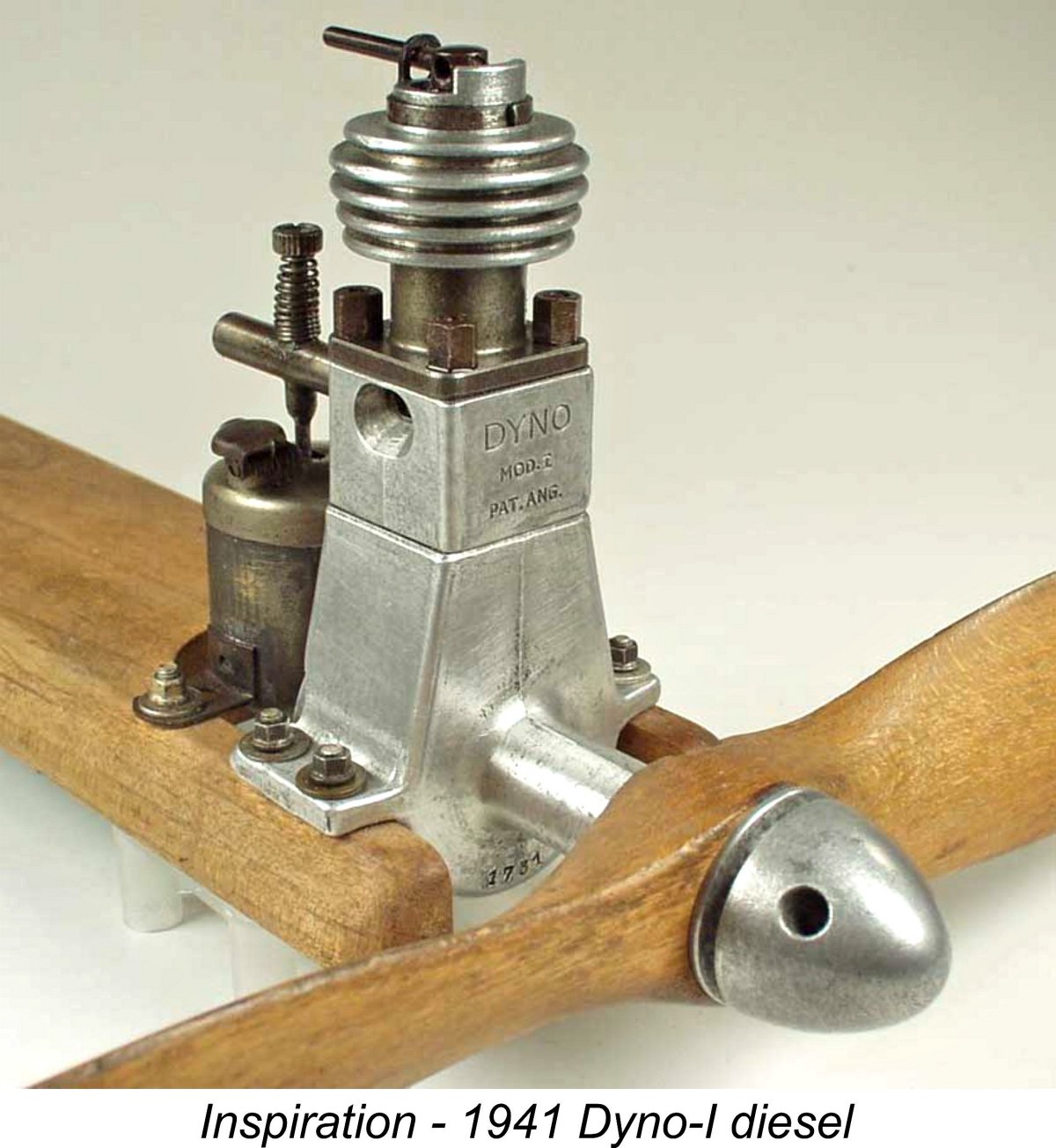 The Mikro engines were manufactured by Kai Nielsen of Kronprinsensgade 8, Copenhagen. Nielsen had established his own business in 1938 primarily as a repair workshop for photographic equipment. His original machine tooling consisted of a single turret lathe! The business was modestly successful, remaining in operation throughout the period of the German occupation of Denmark in WW2 from April 1940 until May 1945.
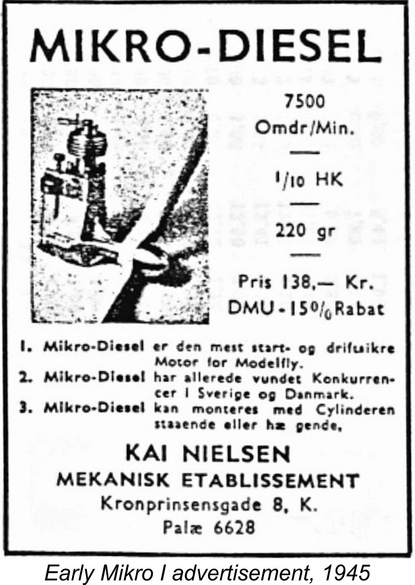 The Mikro I quickly attracted some sales attention from beyond the borders of Denmark, being marketed in Sweden as of 1945 by the noted Swedish model flier, designer, dealer and manufacturer Sven E. Truedsson of Malmö. At that time the engine sold in Sweden for a price of 135 SEK. We encountered Truedsson in connection with the
 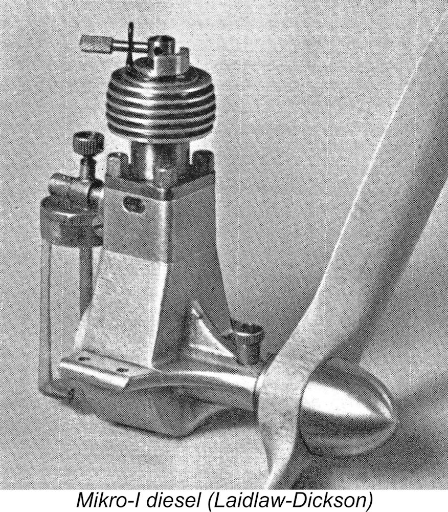 Later versions of the Mikro I showed a few detail changes. Perhaps the most unusual
 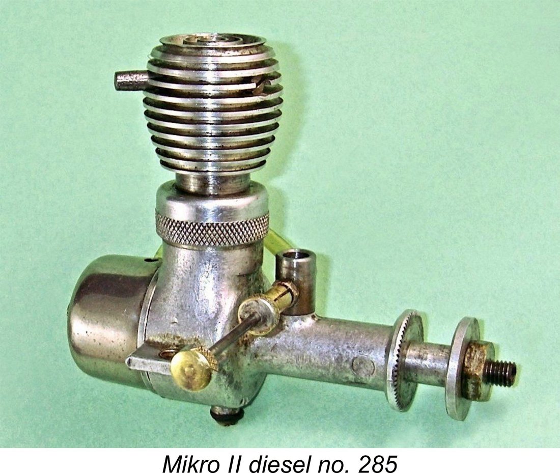 The Mikro II was a comprehensively re-designed 2 cc diesel owing virtually nothing to its sideport Mikro I predecessor. To start with, it featured crankshaft front rotary valve (FRV) induction along with significantly modified internal geometry. The bore was increased to 13 mm with a stroke reduction to 15 mm for a virtually unchanged displacement of 1.99 cc. This change brought the engine far closer to a “square” configuration, in keeping with a developing trend. The new model also weighed far less than its Mikro I predecessor at only 125 gm (4.41 ounces) complete with tank.
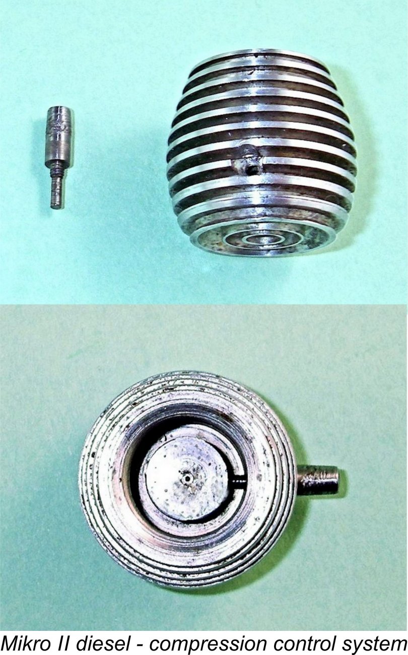 One of the Mikro II’s more unusual design features was its compression adjustment system. The engine featured a conventional contra-piston which was acted upon by a central boss formed inside the screw-on cooling jacket. Compression was adjusted by rotating the entire jacket on its installation thread, exactly as in the
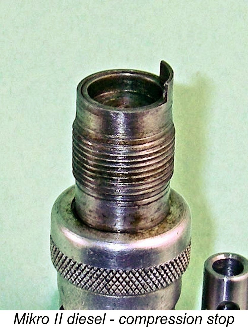
 OK, fair enough - why the two brass machine screws in the holes not occupied by the tommy bar? Surely they’re superfluous? Well, in order to remove the cooling jacket for engine servicing, one had to remove the tommy bar to render the stop ineffective. However, the two brass machine screws would be left in place. This meant that when the engine was reassembled, the tommy bar would always be re-installed into the correct hole established previously. Good thinking here!
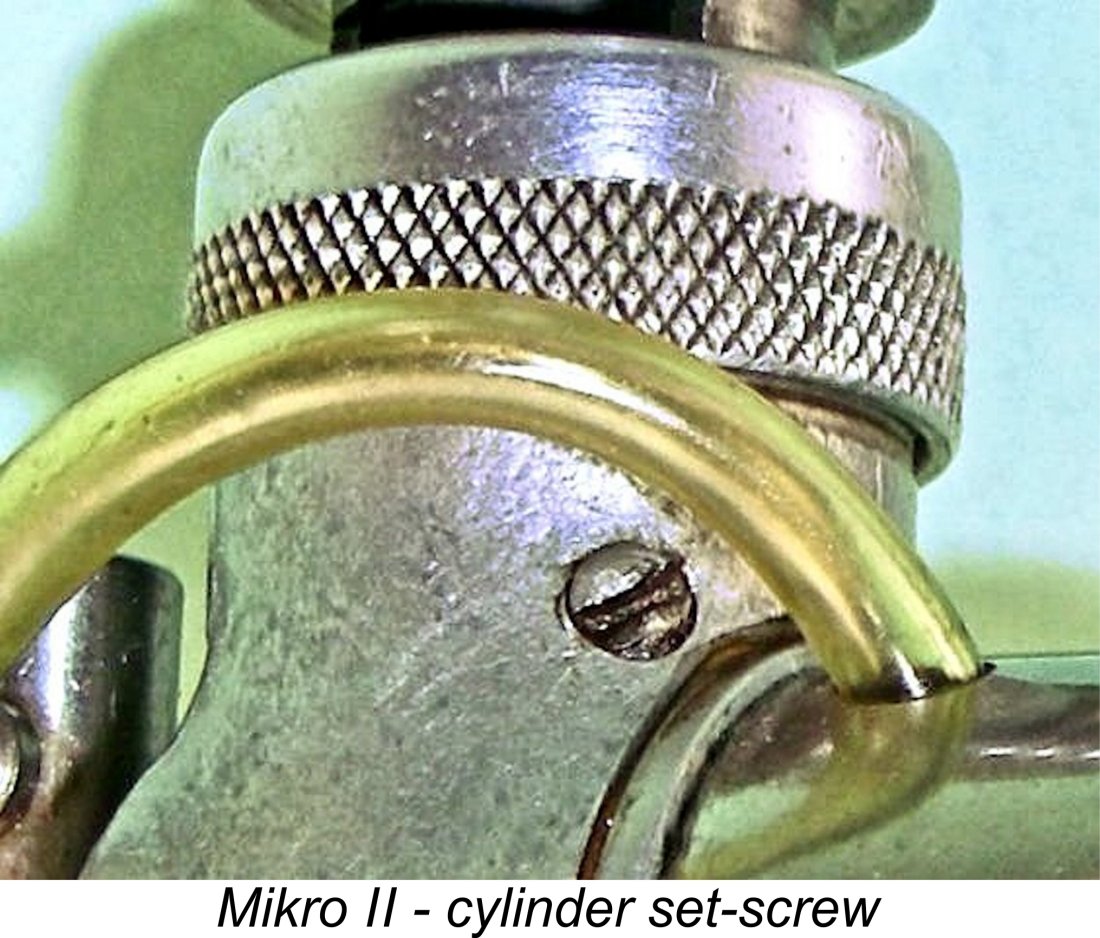 Timing was very conservative. The exhaust opened at 125 degrees after top dead centre for a total exhaust period of only 110 degrees. Transfer opened some 10 degrees later for a period of 90 degrees. It’s clear that high operating speeds were not expected of this engine! However, we might expect to see some pretty solid low-end torque figures.
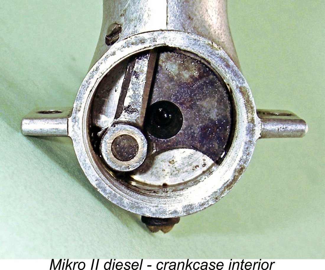 Carrying on downwards, the steel piston drove the one-piece steel crankshaft through a forged steel connecting rod of quite sturdy dimensions. A bronze bushing was used in the big end bearing. The crankshaft featured a heavily counterbalanced crankweb. The shaft ran in a bronze-bushed plain bearing of generous length. The diameter of the central gas passage was a very skimpy 3 mm, although this was tapered out to 6 mm in the section contained within the crankweb. The crankshaft induction port was a similar 3 mm in diameter - pretty marginal for the task, I’d say.
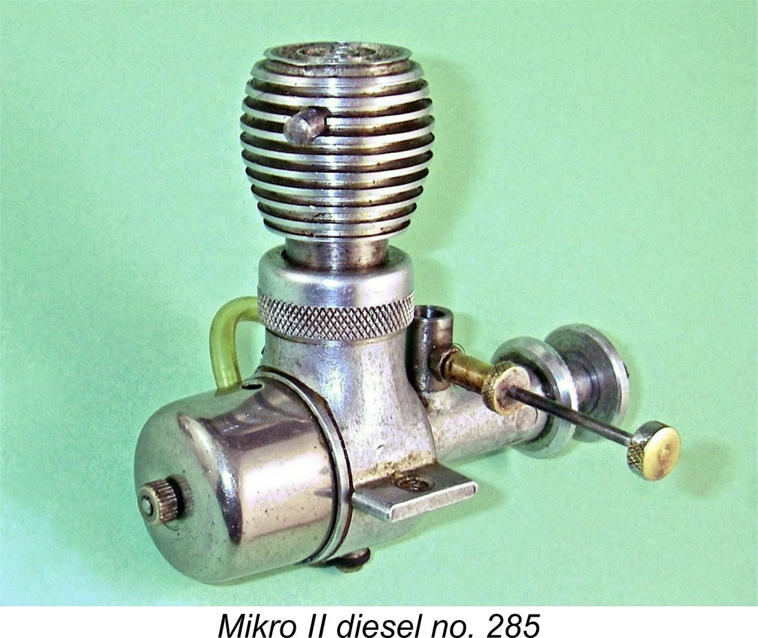 needle valve of considerable length was used, with a brass control knob at the outer end. This component was missing from my example as received - the one in the illustrations is a look-alike component of my own making.
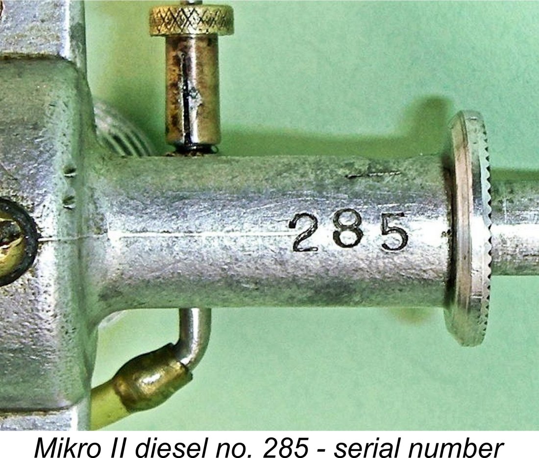 At the rear, the
 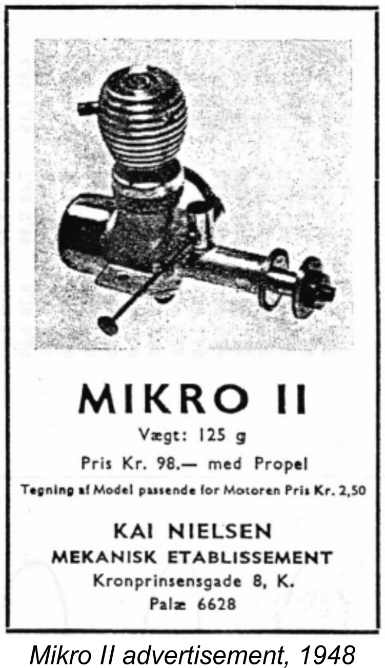 This section of the article won’t detain us long because there isn’t much history to record! As stated earlier, the Mikro II was introduced in 1948 - the engine was first advertised in that year. The price was Kr. 98, including a matching airscrew.
 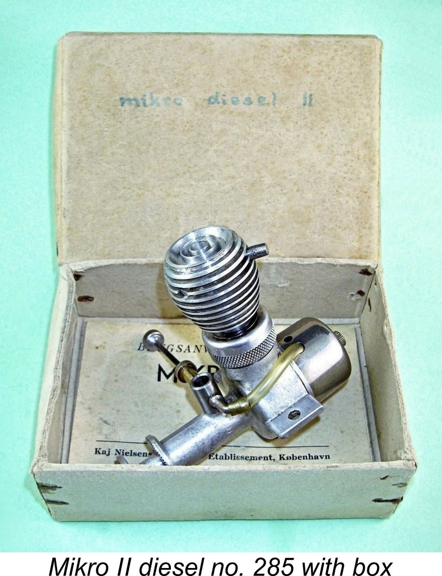 Apart from the engine itself, the box contained a well-printed Danish-language instruction leaflet which was very clearly written as far as it went. Unfortunately, the instructions were extremely vague regarding the effect of changes in control settings, potentially leaving a new user who was unfamiliar with model diesels at a bit of a loss. They also failed to include a description of the way in which the compression control tommy bar could be relocated if necessary.
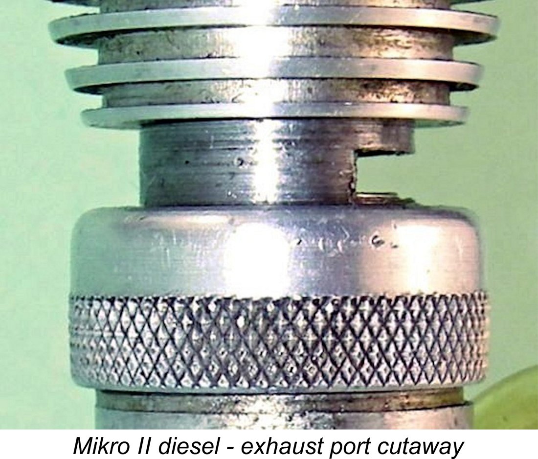
 reputation had already been done. A production series of 1,000 units was apparently planned, but in the event only some 300 examples ended up being completed. Production ended at some point in 1949. The Mikro II is consequently very rare today.
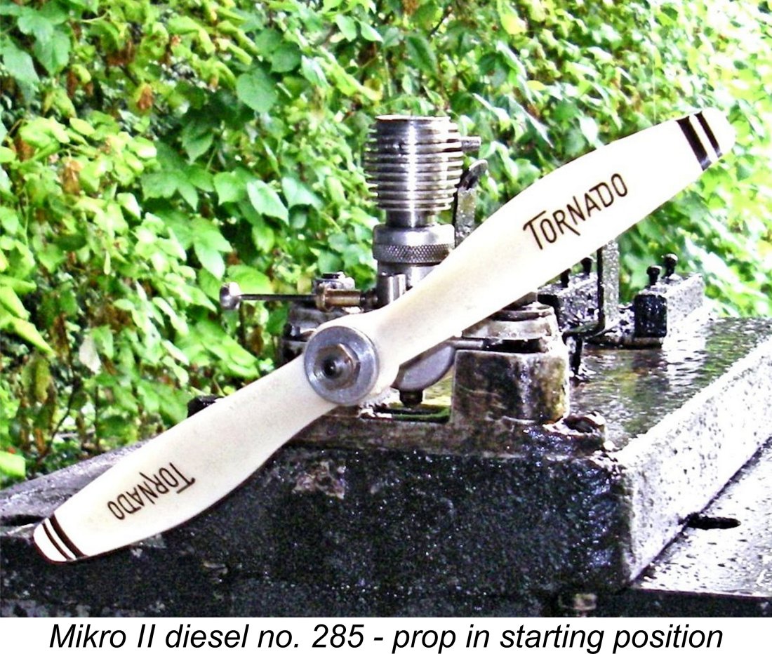
 Unfortunately, the Mikro II didn't exactly fall into this category. It wasn't so much that it was all that difficult to start as that everything had to be just right to get it going - the right needle valve opening, the right amount of fuel in the cylinder, etc. I had no luck at all using the instruction leaflet's recommendation of a single choked flick - that produced no results whatsoever. In fact, contrary to the manufacturer's advice, a small prime seemed to be an essential prerequisite for a prompt cold start.
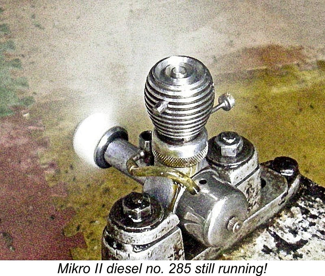
 It seems quite clear that the approach to the design of the Mikro II was driven as much by a desire to reduce weight as by any other factor. In this, the designer succeeded completely - the Mikro II is a full 95 gm (3.35 ounces) lighter than its sideport predecessor of the same displacement. However, that very worthwhile weight reduction came at a price which was far too high - the original Mikro II failed to come close to its Mikro I predecessor in terms of either performance or structural integrity. As such, it can only be viewed as a failure in practical terms. It's therefore no wonder that a revised version of this engine was introduced relatively quickly.
 | |