
|
|
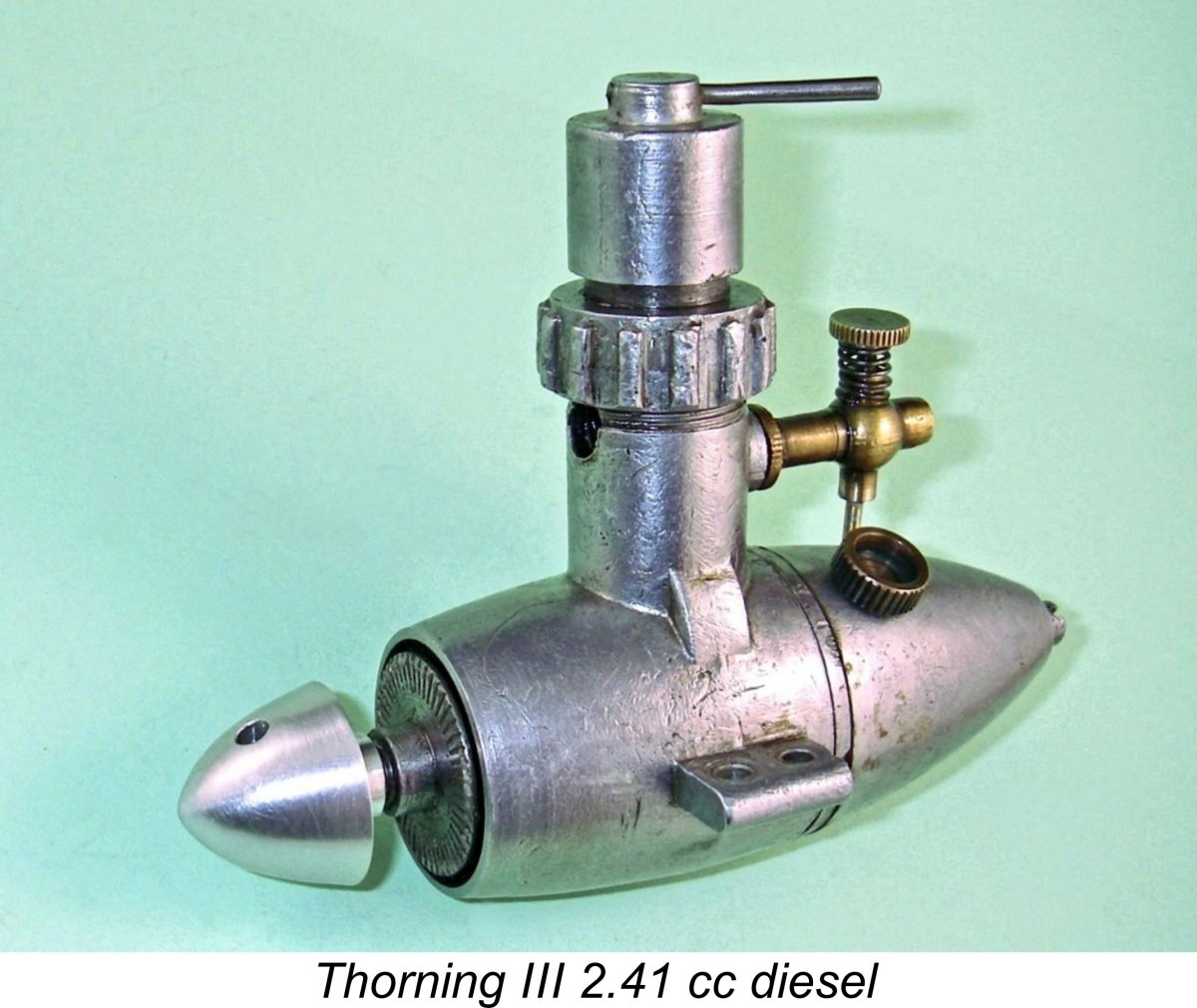
Elsinore “Egg” – the 2.4 cc Thorning III Diesel
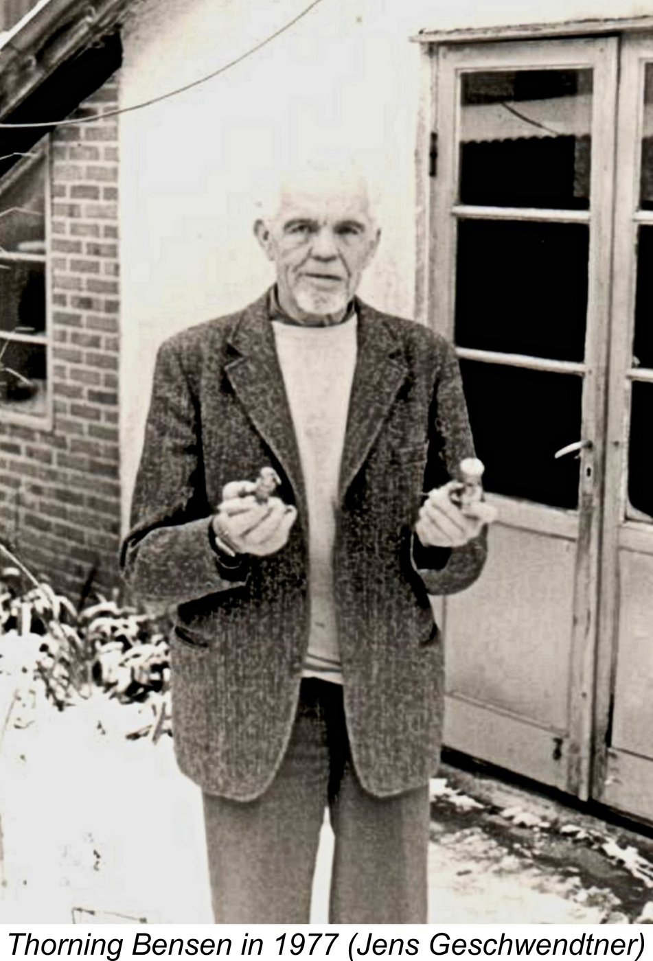
Actually, I prefer the “torpedo” analogy to the seemingly more common "egg" comparison. Moreover, even that isn't the end of the engine's naming complexities - my Danish colleague Jens Geschwendtner has noted that the engine was generally known as the "U-boat" in Danish circles, thus anticipating the nickname that was later applied to the Zeiss Pioneer from East Germany for similar stylistic reasons. Call it what you will ............. In my previous article about the early history of model engine manufacture in Denmark, in which I was helped immeasurably by my valued friend and colleague Luis Petersen, I mentioned the Thorning III in the course of a condensed overview of the series of model engines produced by its manufacturer, Thorning Bensen of Helsingør, Denmark (often referred to in English as Elsinore). However, a significant amount of detail was omitted from that account. Moreover, no present-day testing of any of the engines was undertaken, nor were any technical details provided. This new article will address both deficiencies. Once again, I must record my indebtedness to Luis Petersen for his assistance and encouragement during the preparation of the present article. Having no familiarity either with the Danish language or the Danish modelling scene during the "classic" era, there’s simply no way that I could have written this story without Luis’s kind assistance. I was also greatly aided in this effort by Luis Petersen's long-time friend and competition mechanic Jens Geschwendtner, who not only provided some invaluable information relating to Thorning engines in his possession but also supplied a copy of a most informative article about the Thorning range which he had written many years ago after interviewing Thorning Bensen in person. That article appeared in the February 1978 issue of the Danish model magazine "Modelflyvenyt". Thanks to Jens' effort, a great deal of fascinating first-hand information about Thorning Bensen and his activities was preserved. I freely acknowledge my immense debt to Jens in this regard. As if that wasn't enough, Jens also supplied one of the key test engines to be discussed here.
Having a complete and highly serviceable example of the Thorning III diesel on hand thanks to some splendid efforts on the part of Lars Gustafsson, I’m in a position to present what I believe to be the first-ever detailed analysis and test of this engine to appear in the English language. But before I do so, I think that it’s worthwhile summarizing the events which led up to the appearance of this highly individualistic design. I covered this topic in broad detail in my earlier article about Danish engines, and for many readers that will suffice. Accordingly, readers who feel that they are already sufficiently familiar with this story are invited to skip directly to the subsequent sections, in which the Thorning III and other engines produced by Thorning Bensen will be described in detail. Otherwise, read on …………. The Early Years
Bensen worked as a machinist at the shipyard alongside another individual named Leo Jeppesen, an engineer employed on full-sized marine diesel design. Jeppesen’s close friend and design colleague was fellow engineer Bent Haugård. Unlike Bensen, the two engineering colleagues both had a keen interest in models which had led them to become closely acquainted with two of Denmark’s leading contemporary power modellers, Jørgen Dommergaard and Peter Christiansen. Big thanks to Luis Petersen for supplying At the time in early 1944 when our story begins, Denmark was under an increasingly hostile German administration, having initially been occupied by the Germans beginning on April 9th, 1940 as a result of the implementation of Operation Weserübung. This military operation also resulted in the occupartion of neigbouring Norway. It was a pre-emptive action intended both to secure access to the ice-free Norwegian port of Narvik, thus facilitating the year-round export of Swedish iron ore to Germany, and to prevent the Allied forces opposing Germany from establishing their own bases in those countries and thus stifling vessel movements to and from Germany’s Baltic ports. The occupation of Denmark was to last until German forces finally withdrew at the end of World War II following their surrender in Denmark on May 5th, 1945 and subsequent formal surrender to the Allies on May 8th, 1945.
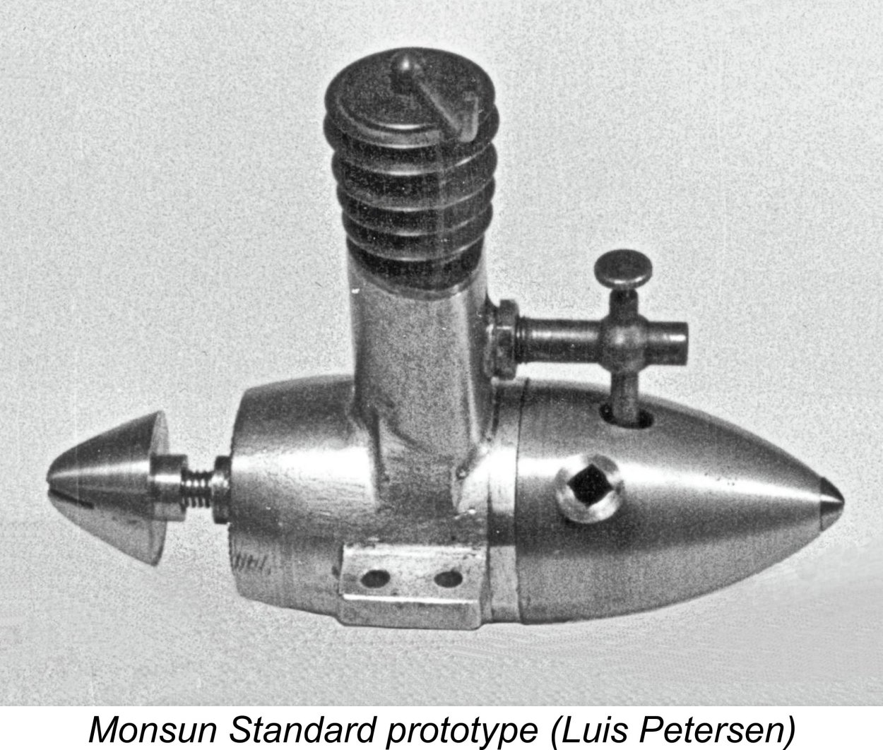
Against this background of increasing tension, a significant number of Danish modellers somehow managed to maintain the pursuit of their chosen hobby. The fact that a market for model engines continued to exist even in the unhappy circumstances of late 1943 is underscored by the fact that Denmark’s (and indeed Scandinavia’s) first commercial model diesel, the 2.4 cc (0.146 cuin.) Diesella from Kolding, made its debut in November 1943. I’ve covered that story in my separate article on the early years of the Danish model engine industry. The perceived existence of a worthwhile market for model Thorning Bensen’s involvement with model engine manufacture stemmed from the fact that in early 1944 his shipyard colleagues Leo Jeppesen and Bent Haugård began collaborating with Jørgen Dommergaard on the design of a 2.4 cc sideport diesel which they called the Monsun (Monsoon) Standard. Since this work had to be carried out during whatever spare time the designers could free up from their regular duties, this naturally took some time. However, by the autumn of 1944 the design had reached the stage at which the construction of test prototypes was in order. Development of The Monsun Standard Once the preliminary design had been completed in the autumn of 1944, the construction of a prototype was undertaken. It was at this point that Thorning Bensen, then aged 38 years, became directly involved. Although not a modeller himself, he had always been attracted to new precision machining challenges, and the construction of a model diesel engine fitted well with this preoccupation. Moreover, he had been looking for a way in which he might become independent and work for himself rather than for an employer. He saw the Monsun project as offering a potential avenue for the achievement of this objective. The construction of the initial prototype was supervised by Jeppesen and Haugård, with the machining being carried out by Thorning Bensen using the facilities of the shipyard's machine shop. Since this work had to be undertaken during off-duty hours when the equipment was not needed for shipyard-related work (largely on German ships during this period), progress was unavoidably slow. However, by February of 1945 the first prototype was finished.
One of the updated prototypes was retained by Leo Jeppesen for bench testing, while others were given to Jørgen Dommergaard and Peter Christiansen for flight testing. Jeppesen's example was subjected to a series of bench tests which cumulatively added up to over 100 running hours, including several continuous runs of up to eight hours duration. This performance was sufficiently impressive to rate a mention by D. J. Laidlaw-Dickson in his widely-read 1946 book on model diesels. Luis Petersen has confirmed that Jeppesen's bench-test prototype still exists at the Technical Museum in Helsingør. Despite the running time of over 100 hours which this engine has accumulated, Luis advises that it remains in perfect condition. 100 hours?!? As my late and much missed mate Ron Chernich commented, model diesel fuel must have been a heck of a lot cheaper back then! Moreover, Jeppesen & Co. must have had accommodating neighbours ……..... presumably this testing took place at the shipyard. Other prototypes were extensively air-tested by Jørgen Dommergaard and Peter Christiansen. One of these engines reportedly accumulated over 20 hours of airborne running with no ill effects. Few model engines have been subjected to such an exhaustive prototype testing program as the Monsun Standard! Let's have a closer look at the design which resulted from all of this development work. The Monsun Standard - Description
It’s difficult to avoid the conclusion that the designers of the Monsun were influenced to some degree by the Diesella's rather individualistic styling. Indeed, we know from his later writings that Dommergaard was highly cognizant of the Diesella's main design features. Beneath its individualistic external appearance, the Monsun Standard appeared at first glance to be a basically conventional long-stroke sideport diesel of its era, seemingly owing much to the functional design of the Swiss Dyno 2 cc unit which dated from 1941. With a bore of 12.7 mm (0.500 in.) and a stroke of 19 mm (0.748 in.), the engine had a displacement of 2.41 cc (0.147 cuin.). Basically conventional it may have seemed apart from its styling, but there was nothing conventional about the engine’s cylinder porting arrangements! Luis Petersen tells us that the Monsun’s unique scavenging and timing arrangements were actually copied from a DKW two-stroke car engine which had been designed by a Danish engineer, Jørgen Skafte Rasmussen. DKW was later to evolve into the Audi car line. The original prototypes of the engine featured twin bypass passages placed one on each side of the induction port at the rear and extending above the induction port to provide the appropriate timing. Due to the need to accomodate the two rearward-located bypass passages, the upper portion of the sandcast crankcase had a triangular section with the rounded apex towards the front. The single exhaust port in these prototypes was also located at the rear - Luis Petersen has examined the surviving prototype at the Helsingør Technical Museum to confirm this. The design drawings which were eventually finalized by Leo Jeppesen also showed a rear exhaust port, and most of the "production" engines (like that illustrated as reproduced above by D. J. Laidlaw-Dickson in his previously-referenced 1946 book) seem to have incorporated this feature.
The cylinder liner was a screw-in item. Given the requirement that the cylinder ports be aligned with their counterparts in the crankcase casting, this required that a test assembly (with gasket) be undertaken prior to the cutting of the cylinder ports, the matching of the cylinder installation flange to the triangular upper crankcase section and the finishing of the bore so that the ports could be marked for cutting in their correct locations using a jig following the temporary withdrawal of the cylinder. A number of other engines of the era used this approach, notably the English AMCO .87 model. Jørgen Dommergaard was convinced that cooling fins were unnecessary on a diesel – he actually claimed that he only went along with their inclusion on the Monsun Standard because the paying customers would expect to see them! He gave his reasons for this belief as being based upon the very high latent heat of evaporation of the ether which made up a major proportion (50% or more) of the diesel fuel then in use. The evaporative cooling of the incoming fuel mixture which resulted from this property of ether in turn promoted effective internal cooling of the engine. A most revealing article (in Danish) by Dommergaard comparing the design of the Monsun with that of other model diesels then available in Denmark appeared in the April 1946 issue of the magazine “Luftsport”. In this article, Dommergaard also explained his conviction that the use of ball races to support the crankshaft (as featured in the Diesella) was an unnecessary refinement. He believed that a well-fitted bronze bushing offered comparable levels of friction and wear resistance to those of a ball race. The design of the Monsun reflected this conviction. Monsun Production Commences By the late summer of 1945 the testing program described earlier had been successfully completed. At this point, Leo Jeppesen completed the final design drawings upon which the production engines were to be based. It was now time to make the necessary arrangements to put the engine into series production. The after-hours use of the shipyard machine shop facilities to turn out a few prototypes was one thing - the commercial series manufacture of the finalized design was quite another. It would clearly be impossible to use the shipyard facilities for this purpose - they were there to be used for marine engineering work, not commercial model engine manufacture. Accordingly, if series manufacture of the engine was to proceed, alternative arrangements would have to be made. This of course was the opportunity for which Thorning Bensen had been waiting. He ended his employment at the shipyard and established himself in a basement workshop located on Mads Holms vej in Helsingør. There he commenced the series production of the Monsun Standard. The goal at the outset was to produce a run of 100 examples of the engine.
So far, so good! However, a very large fly soon manifested itself in this particular ointment! The quality of the engines reportedly suffered greatly through this change of manufacturing venue, possibly as a result of the accelerated production schedule required to meet the target as well as the fact that Bensen was working alone at this time. It's probable too that like the majority of early post-war small-scale model engine manufacturers established on a shoe-string budget, he was using well-worn second-hand war surplus equipment during this start-up phase. The use of inferior materials may also have contributed to this deterioration. The original prototype materials came from the shipyard, but those available to Bensen from other sources may well have been sub-standard. Whatever the reason, this deterioration in quality led Leo Jeppesen to withdraw from the project quite early on, although he retained his original drawings, which still exist in the keeping of Luis Petersen. Thereafter, Thorning Bensen continued on his own. Around 100 examples of the Monsun Standard did end up being manufactured by Bensen between late 1945 and mid 1946, but Luis Petersen estimates that only perhaps ten of these came anywhere near the standard of the original prototypes. As far as Jens Geschwendtner is aware, none of these series production models survives today.
This design too was specifically mentioned by Laidlaw-Dickson in his previously-referenced late 1946 book. The name change of course reflects the fact that Thorning Bensen was now solely responsible for the manufacture and marketing of the engines following the withdrawal of Leo Jeppesen. Clearly he wanted to establish himself as a “name” model engine manufacturer in his own right. The Thorning Bensen 1A was in essence a Monsun Standard which used a finless moveable head for compression adjustment. In the revised design, the underside of the head was in direct contact with the top of the contra-piston, allowing compression adjustment to be effected by the rotation of the entire cylinder jacket on its installation thread rather than by a conventional compression screw threaded centrally through the top of the jacket. In addition, a modified cylinder assembly using a “dog collar” was employed in place of the former screw-in construction. In this arrangement, the cylinder was held down by an internally-threaded machined alloy ring which engaged with an external thread at the top of the crankcase and held the cylinder in place using a suitably-dimensioned internal shoulder which bore upon the cylinder installation flange. This had the great advantage of eliminating the need for a trial assembly prior to the completion of all machining operations on the cylinder.
The cylinder porting arrangements in the Thorning Bensen 1A were modified from those which had been featured in the original Monsun prototypes, with a front exhaust now being employed. The induction and bypass porting was however retained unaltered. The sandcast triangular section upper crankcase casting was necessarily retained to accomodate the twin rearward bypass passages. This very rare model does not appear to have remained very long in production. In fact, Luis Petersen believes that only about 6 examples were made. The design evolved fairly quickly into the next design to be discussed in detail – the far better-known Thorning III 2.4 cc diesel which forms our central subject. For reasons which are now obscure, the Bensen portion of the brand name was dropped with the introduction of this model, never to reappear. There's also a bit of a mystery surrounding the engine's name - we know about the Thorning Bensen 1A and Thorning III designs, but where are the Thorning Bensen I and II models which are clearly implied?? Luis Petersen and Jens Geschwendtner interviewed both Leo Jeppesen and Thorning Bensen, neither of whom mentioned such models. For my part, I consider it most likely that the Thorning III name stemmed from the fact that it was the third model diesel design to be manufactured by Thorning Bensen under his own name, regardless of the names of its predecessors. In this scenario, Bensen may have come to see the Monsun Standard examples that he made on his own following the departure of Leo Jeppesen as the Thorning I. The fact that it was never named as such in the promotional literature does not exclude the possibility of Bensen viewing it in that light. If that was the way in which Bensen saw things, then some logic begins to emerge As it happens, there is irrefutable evidence in the form of a surviving engine now in my possession thanks to the kindness of my friend Jens Geschwendtner that Bensen experimented with a "lightweight" version of the 1A model, probably during early 1946. The main casting of the example in question is formed without the streamlined front bearing cover - it hasn't been machined off, it was never there. There is also no provision for a tank. This example retains the sandcast crankcase with triangular upper section that was a feature of both the Monsun (or Thorning I?) and the Thorning Bensen 1A. This appears to confirm that it pre-dates the Thorning III. However, the two expansions at the rear for the bypass passages are not internally machined. Instead, the engine uses what appears to be a standard Thorning III-type cylinder liner with twin bypass/transfer slots at the sides of the lower cylinder wall to go along with the single front exhaust port. It also features the two-piece contra piston of the Thorning III, of which more below in its place. This very clearly implies that it is a transitional design lying between the Thorning Bensen 1A and the Thorning III. Could this be the missing Thorning II design .........?!? It seems not unlikely. This particular example is also rather unusual in that it has very short mounting lugs on both sides with only one mounting hole apiece. There's clear visible evidence that the crankcase started out as a conventional casting with regular four-hole lugs. However, the front half of the lugs has been very cleanly and neatly It appears from this that the engine was possibly intended for car service or for some other application in which available space dictated an unusual mounting configuration. Alternatively, it could be an experimental unit that never actually saw series production. We'll probably never know which of these possibilities is correct. Whatever the truth of this matter, the engine is extremely well fitted, starting easily and running very nicely. Based on a few spot checks, its performance is very similar to that of the Thorning III (see below). We'd expect this given the identical functional designs of the two engines. The design of the next engine in the series, the Thorning III, represented a further simplification of the original Monsun and its Thorning Bensen 1A successor, primarily to reduce manufacturing costs. To support the increased production rate which was clearly anticipated for the new model, Thorning Bensen invested in some new equipment at this time, including the production of permanent molds for the castings. Bensen also took on two additional workers besides himself. The Thorning III entered production in late 1946. It sold very well indeed right from the outset, becoming the most widely-used model engine in Denmark for some years following its introduction. Consequently it is undoubtedly the best known product of the Thorning Bensen workshop since it was made in relatively large numbers between late 1946 and 1950 – about 1200 examples in all, some of which found their way beyond the borders of their native Denmark. Let's take a closer look at this highly individualistic design. The Thorning III Diesel
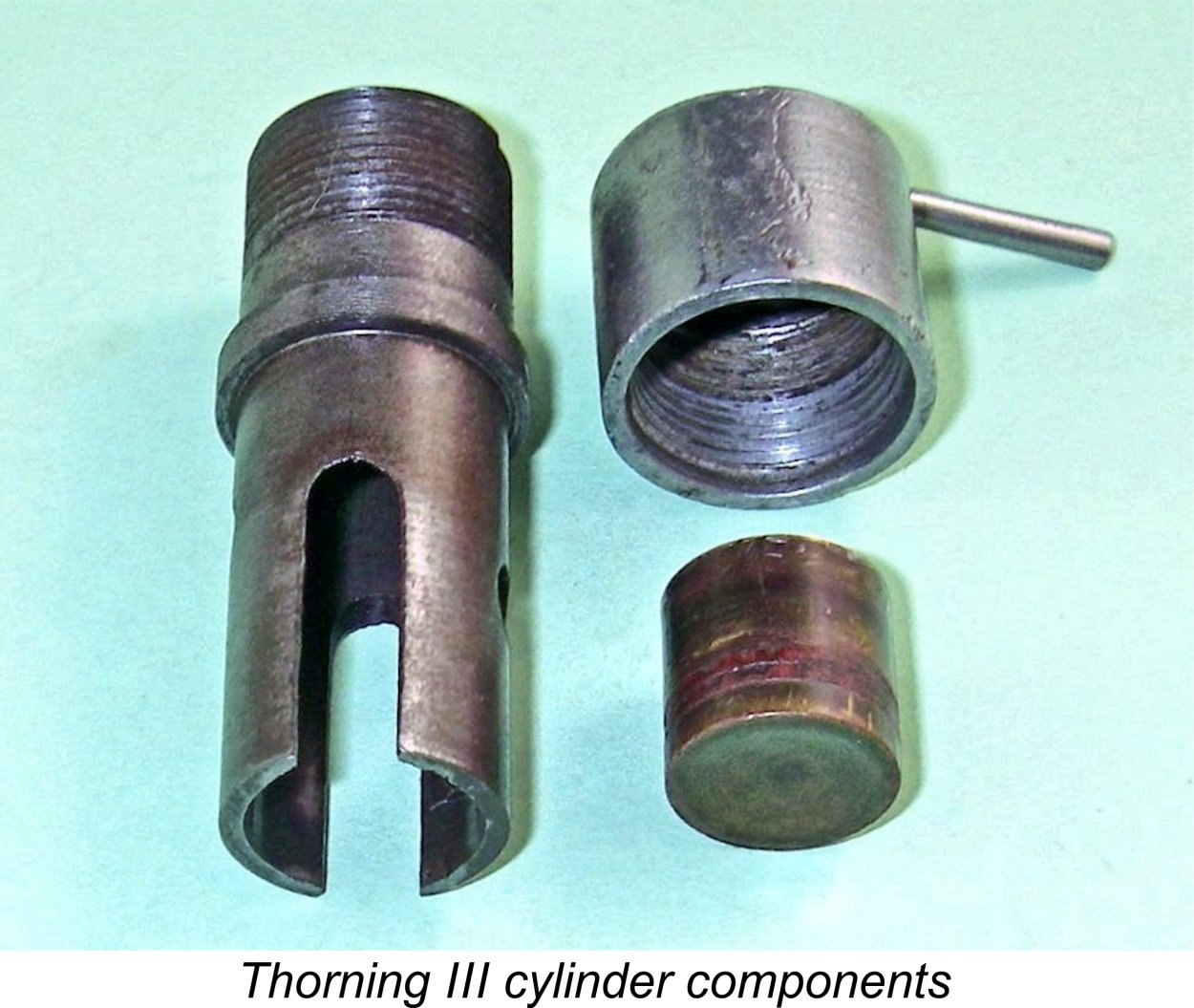
The engine was built up around a rather massive crankcase which was produced by gravity die-casting instead of the former sand-casting. This alone suggests that Thorning Bensen was anticipating a significantly increased production rate for this model. Actually, this casting isn’t quite as massive as it appears – the streamlined main bearing housing at the front is largely hollow, with its open end being effectively closed by the recessed large-diameter steel prop driver. The visible streamlined front housing is little more than a shell. The main bearing housing inside this A few things remained unchanged, including the nominal bore and stroke figures of 12.7 mm (0.500 in.) and 19.0 mm (0.748 in.) respectively for a displacement of 2.41 cc (0.147 cuin.). That said, it’s a bit odd that the engine was always cited as a full 2.5 cc model in all promotional literature. The engine weighed in at a hefty 183 gm (6.45 ounces) with tank, which could be reduced quite substantially by the simple expedient of removing the very heavy standard tank. The tank incidentally was also produced as a gravity die-casting. So far, so similar ......however, this model departed from the design of its predecessor in a number of key respects. It retained the forward-facing exhaust of the This arrangement ended the necessity of providing cast or machined bypass passages in the upper crankcase casting, which was now circular in section rather than triangular. This bypass design was later to reappear in the Danish Viking 2.5 cc sideport diesel of 1950. In fact, the Thorning III employed a cylinder porting system which was to be repeated in almost every detail in the Viking. Port timing figures for the Thorning III were quite reasonable for a sideport engine of this vintage. As measured by Maris Dislers, the exhaust period is around 150 degrees of crankshaft angle, with the transfers having around a 120 degree period. The induction period of some 100 degrees (50 degrees each side of top dead centre) is about as much as one can reasonably expect from a long-stroke sideport engine. By rough "eyeball" estimates, my example appears to match those figures quite closely.
Although the “dog collar” was somewhat intrusive in terms of the engine’s external appearance, there was sound engineering logic behind its employment. If the two “halves” of the lower cylinder on either side of the bypass slots were to be subject to hold-down stresses, there would be a considerable potential for distortion though buckling, with consequent "pinching" of the piston in the lower bore. This was a well-documented problem with the later Viking 2.5 cc model. The Thorning III’s use of a location flange just above exhaust port level which bore upon the top of the crankcase casting got around this issue very nicely – since the “dog collar” bore only against the location flange, the cylinder liner itself was left completely free from hold-down stresses throughout its length. The arrangement also left the upper cylinder completely unencumbered and hence able to accommodate the engine’s compression adjustment arrangements described earlier. The cylinder jacket continued to be completely devoid of any vestiges of cooling fins. This jacket was a lightweight casting which was internally threaded to match the upper cylinder. The provision of a tommy bar of generous length was a greatly superior arrangement to the “penny slot” used in the E.D. Mk. II (and also a penny cheaper to use!).
The idea was to allow the packing ring to do the major portion of the sealing without the brass piston itself having to be too tight a fit. The intent was that the lower contra-piston element would be pushed up against the resilient packing ring by compression and combustion loadings, tending to expand the packing ring laterally against the cylinder walls. The idea of achieving a good compression seal without the use of an excessively tight contra piston was entirely consistent with the use of a brass contra-piston. Since a brass contra-piston has a significantly greater coefficient of thermal expansion than a steel cylinder, it has to be fitted relatively loosely to avoid thermal siezure in the bore at operating temperatures. Although differing in execution, the arrangement employed by Bensen was broadly similar in concept to the O-ring system used much later by both McCoy and International Model Aircraft (IMA - FROG) in their respective small diesel models of the 1950’s. The as-new examples of this engine owned by Sten Persson and Kjell Lindqvist both retain graphited yarn wraps as described above. However, my good mate Maris Dislers reports that his example has what appears to be a continuous ring made of what appears to be leather. This may be an owner modification, or it could be an alternative material selection on the part of the manufacturer. Either way, Maris's unit apparently seals perfectly and works very well indeed with the engine in use. Luis Petersen believes that the leather washer was the original fitting, but there is presently a divergence of opinions on this. Perhaps the manufacturer used both methods depending on what was available at any given time?!? As received, my example of the engine had very poor compression. A quick examination revealed that almost all of the leakage was coming past the contra-piston – the original packing had been replaced by a pair of fibre rings which had deteriorated to the point where they had lost their resilience (if they ever had any to begin with!) and had cracked, hence losing their ability to perform their sealing function. Lacking any suitable graphited yarn at the time when this engine was scheduled for testing, I was forced to make a new cast-iron contra-piston which was lapped to what I considered a perfect fit in the steel bore. This sealed perfectly, restoring the compression completely. Thanks to the kindness of Kjell Lindqvist and Lars Gustafsson, I now have some graphited yarn with which I have restored the original component, with good results. As an aside, the example of what I believe to be the Thorning Bensen II described above is fitted with a high-temperature O-ring rather than any form of packing. This seems to work pefectly - as reported earlier, that engine starts and runs very well indeed. The use of a suitable O-ring thus appears to be a perfectly legitimate fix for any example of a Thorning engine exhibiting sealing difficulties with a split contra-piston. The working piston construction too is worthy of comment. Like the cylinder, this component is made of steel, resulting in the often-problematic combination of a hardened steel piston working in a hardened steel bore. With such a combination, the initial fit and finish are of paramount importance since running-in wear is likely to be minimal. In the case of my example, this fit was very good, so no worries there. Maris reports that the compression seal in his example is a trifle “soft”, but there’s still plenty of compression for starting.
Of course, with fairly large circular fore-and-aft exhaust and induction ports, it’s essential to secure the gudgeon pin against lateral movement in order to preclude fouling of the ports. However, this is the first engine of my personal acquaintance in which brazing has been used to achieve the required stability. Maris Dislers tells me that some of the very early Komet engines made in Västerås, Sweden by the Johansson brothers also featured brazed gudgeon pins. Perhaps that’s where Bensen got the idea …………. There’s a huge downside to this approach – changing the rod and/or the gudgeon pin while retaining the original piston becomes impossible. Since the piston was very nicely fitted, I decided to leave things as they were, sloppy rod and all. If I wished to switch rods, the most practical approach that I can think of would be to make a new piston as well, using a pressed-in gudgeon pin. This latter approach was used in the Viking 2.5 cc model which was internally based in large part upon the Thorning III, as mentioned earlier. The crankshaft was a one-piece steel component having a counterbalanced crankweb. I couldn’t shift the recessed steel prop driver from its installation taper using what I considered to be fair means. Therefore I couldn’t remove the shaft for inspection. However, a Danish test report (see below) confirmed that it ran in a bushing of some unspecified material which Luis Petersen tells us was generally bronze. All I can report is that it seems to be a perfect fit in said bushing.
The carburettor unit screwed into a threaded boss on the crankcase which corresponded to a single circular induction port of generous size at the rear of the cylinder liner. The carburettor was locked in position using an internally-threaded knurled ring. The tank was a massive affair which was formed by gravity die-casting. A length of brass tubing which also served as the jet was soldered into the carburettor body. This tube penetrated into the tank through a suitably-positioned hole at the top. The size of the tank was grossly excessive for free flight use, making it seem likely that it was primarily intended to be used for bench-testing or in model boat/car service. It was fitted with a substantial brass screw-in filler cap. Thorning Bensen's method for testing the performance of his engines was unique in my experience. When speaking with Jens Geschwendtner, he recalled that he did not owned a workable rev counter for use during testing of his designs. Instead, he inserted an offset pencil tip in the spinner, started the engine with this pencil securely in place (one hopes!) and then held a large cardboard sheet in position to contact the pencil tip for a specified length of time while moving the sheet about. The speed of rotation was read by counting the pencil marks and converting to marks per minute! The application of serial numbers to these engines appears to have been somewhat haphazard. In the late O.F.W. Fisher’s well-known 1977 book “Collector’s Guide to Model Aero Engines”, the illustrated example reportedly displayed the serial number 014, while engine number 2056 appeared in a discussion thread on a widely-read modelling forum. Engine number 3124 has also been reliably reported from Sweden. However, my own example bears no such number, nor do the units owned by Kjell Lindqvist, Jens Geschwendtner and Maris Dislers. It seems that there was no discernable pattern to the application of serial numbers, which therefore tell us nothing about production figures. We are forced to rely upon the figure of 1200 units obtained by Jens Geschwendtner during his interview with Thorning Bensen.
I should mention that there was a second variant of the engine called the Thorning III A. This was essentially the same engine fitted with a flywheel and universal coupling in place of the standard spinner and prop driver. It was intended for use in model boats or tether cars, then very popular. The distribution of the Thorning III was very capably managed. A number of major stores in Copenhagen stocked the engine, while broader distribution was handled by the well-known Danish firm of Danske Modelflyve Industri (DMI). In March 1948 the Thorning III was advertised in the magazine “Flyv” by DMI at a retail price of 59 kr., with the companion Thorning III A model on offer for 69 Kr. These prices apparently remained unchanged right through to the end of production. Export sales were reportedly handled by the Copenhagen firm Brøste. However, trade restrictions prevented the development of a major export market, although some examples did find their way to Sweden, where they had to face stiff competition from the well-established Swedish Komet marque. The Thorning III was a steady seller right from the start, becoming the most widely-used model engine in Denmark for some years. In a 1977 interview with Jens Gschwendtner, Thorning Bensen (then aged 71 years) recalled that the engine won several Danish championships, also establishing a few Danish records along the way. According to Bensen, its high point was apparently a 3rd place finish in an unspecified International control-line competition. Incidentally, at the time of this interview Bensen's backyard workshop in which the Thorning engines were manufactured remained completely intact, 26 years after the last model engine had been made there! OK, so now we know a little about the design, construction and marketing of the Thorning III. Next question – how does it run?? Let’s find out!! The Thorning III Diesel on Test
Here we need to be very specific regarding the identity of the publication in question. This magazine was in effect a short-lived (1948-1951) Danish equivalent of the far better-known Swedish publication "Teknik för Alla" (1940-2001). The two are quite distinct publications, although it appears likely that there was a connection of some kind between the two similarly-titled magazines. The Danish magazine was published in Copenhagen. It's all too easy to become confused between the two publications - I certainly did for a while! You really have to pay attention to the spelling........... The writer of the “Teknik for Alle” report stated that the choice of the Thorning III as the subject of this initial test was based upon the fact that it was the engine that had been “most widely used” in Denmark up to that point. This represents a solid contemporary testimonial to the engine’s popularity. Sadly, the writer of this report may have been directly responsible for the irreparable damage of a good number of these engines, because he noted the engine’s rather considerable weight and spent a significant portion of the article telling his readers how to eliminate some of this weight by throwing away the standard tank and removing the streamlined front bearing housing using a hacksaw! AAARRRGGGHHH!! Sten Persson from Sweden has commented that the reason why not many of these engines survive today in complete and original condition is because far too many owners followed this advice! One actually wonders how many enthusiastic modifiers who didn’t fully understand the engine’s structure managed to remove or at least seriously weaken the internal main bearing housing as well ……..
The engine reportedly ran well over a speed range of 2,000 to 8,000 RPM. A peak output of 0.110 metric horsepower (hk, equivalent to 0.108 BHP based on the applicable conversion factor of 1.014) was measured at a somewhat vague peaking speed of between 6,000 and 7,000 RPM. This implies that, as we would expect, the Thorning III is far more about low speed torque than peak power output at higher speeds. This expectation guided my own choice of test airscrews. One anomaly in the reported figures centres around the claimed performance on one specific prop. The writer seems to have viewed a 25x20 prop (a slightly undersized 10x8) as a “normal” prop to use with this engine. On such a prop, the engine reportedly managed speeds of “up to” 5,000 RPM on the bench. The anomaly is that the writer also stated that when running at a speed of 4,500 RPM on this prop, the engine was developing 0.099 BHP! The published power curve reflects this figure, but it’s really hard to see how, if the engine really developed 0.099 BHP @ 4,500 RPM, it could peak out at 0.108 BHP at around 6,500 RPM………………… in the real world, power curves are almost never that flat!! One of those anomalies that research of this kind throws at us!
A few interesting observations arose from Maris’s testing. First, the composite contra piston with its leather seal worked perfectly, allowing for very smooth and precise compression adjustments. Secondly, his engine showed no tendency to sag as it warmed up, despite the fact that blow-by due to his example's rather “soft” compression seal might be expected to generate excess heating. Thirdly (and perhaps most oddly), his example showed a marked preference for a nitrated fuel – rather unusual with low-revving sideport engines, especially one with marginal cooling arrangements! Finally, he found that the engine’s response to needle valve adjustments was “vague”. When preparing to test my own example of the engine, I chose to begin with an un-nitrated fuel, since that was what was recommended by the manufacturer and used in the original “Teknik for Alle” test. Apart from that, I reasoned that with no cooling fins to get rid of excess heat it would be wise to use as cool-running a fuel as possible. I therefore elected to try the engine on my usual brew for early long-stroke diesels – a straight mix of equal parts of kerosene, ether and castor oil. I felt that the high oil content would do much to help the sloppy con-rod bearing to get through the test. My example of the engine is fairly well used and has the previously-noted rod bearing wear to prove it. However, all other fits remain well within operational limits, so I felt confident that the beast had a few test runs left in it! In particular, compression is ideal – a perfect wet seal for starting but no trace of “stiction” in the bore at any point of the stroke. The spinner nut and tank filler cap were missing as received and have been replaced by “look-alike” components of my own making which of course have no effect upon performance. The balance of the engine is completely original, making it a representative test subject. In order to spare the light alloy spinner nut from the ravages of repeated prop changes during testing, I made up an appropriately-threaded (M6x1.0) steel sleeve nut and washer. I’d recommend the same approach to anyone planning to do a lot of running with one of these engines or others of equal rarity – conservation is important! I did however use the alloy component for the accompanying photographs.
The engine was a bit of a challenge to start for the first time since I had used rather a lot of oil during the re-assembly process, including a healthy dose of molybdenum disulphide. Clearing all the excess lubricant took some time, but eventually the thing fired up OK. Subsequent starts were far easier – just a choked flick and a small prime, and away she went. When hot, the prime could be omitted. My replacement contra piston proved to be perfectly fitted, allowing for easy compression adjustments at all times while maintaining a good seal and holding its settings very securely. Once running, a few peculiarities were quickly noted. Firstly, the engine did run very hot, tending to sag by a few hundred RPM as it warmed up and requiring a compression reduction. The finless jacket became really hot after a while – fingers beware! I can’t help feeling that the omission of the cooling fins may not have been the very best idea …………. doubtless for this reason, I found that for greatest consistency a slightly rich mixture worked best, at the cost of a few hundred RPM. I hasten to add that this problem is not down to blow-by past the piston, which is an excellent working fit in the bore. Secondly, while the needle valve offered very accurate fuel metering thanks to its fine external thread, there was an appreciable delay between a change in setting and its observable result. This must be a design characteristic, since there’s no trace of base leakage in this example – I tested it for that both before and after the test. This made the establishment of optimum settings a bit more challenging than it might have been. In my book, this confirms Maris Dislers’ observation that needle response is “vague” – couldn’t put it better!
In view of the sagging problem mentioned above, the engine really generated two sets of figures – the best that it could achieve while warming up, and the best that it could sustain while running the tank out. The sagging had nothing to do with tight fits – the piston is perfectly fitted and the entire engine has a delightfully “free” feel to it, hot or cold. The cuprit is the excessive operating temperature resulting from the absence of any cooling provisions. The engine would undoubtedly give its very best in a free flight model on a 20 second run if started at running settings and launched more or less immediately. Since it would represent the engine’s “real-world” performance, I elected to report the figures which the engine would sustain for each prop once warmed up. The engine could typically manage figures that were 200 to 300 RPM better on each prop during the early part of the run, but could not sustain those figures for the full length of the run. The following numbers are those realized in the steady state:
The above data imply a fully warmed-up steady state peak output for this example of some 0.075 BHP @ 5,600 RPM on the un-nitrated fuel used. This is well down on the performance reported by the “Teknik for Alle” writer in August 1950, also falling considerably short of Maris’s estimates. However, the Danish tester may possibly have been flattering the engine by reporting “best” figures. If I had done the same, my results would likely be far closer to his. I remained mindful of the fact that Maris’s figures were obtained using a nitrated fuel, for which he said that his engine indicated a marked preference. Reasoning that my example might well display a similar response, I repeated the test using a nitrated fuel mixture. I have to say that this re-test completely supported Maris’s observations! The engine ran far better on this fuel, requiring a considerably lower compression setting for smooth running. Even the needle response seemed to be improved, while the tendency to sag was also far less of an issue. Running was very smooth and consistent on all props, which were the same ones used in the earlier test. The results below speak for themselves:
The above are steady-state figures once again. On the nitrated fuel, the engine managed a sustained peak output of around 0.087 BHP @ 6,000 RPM – very close indeed to the provisional results reported by Maris Dislers. However, neither of us seem to have generated any support for the figure of 0.108 BHP at between 6,000 and 7,000 RPM quoted by the “Teknik for Alle” tester. I’m pretty confident that a well set-up example in good condition might manage 0.100 BHP at around 6,400 RPM, but that’s as far as I’d go. Even so, the engine will swing a pretty substantial prop at or near its peak output level. Allowing for airborne pick-up, a 10x8 (the latter being the “normal” prop according to the original Danish tester) would probably be a very good size to use with this engine. Such an airscrew would approach peak in the air and would shift a meaningful amount of air, allowing the engine to fly a fairly large model to good effect. The engine’s generally excellent handling qualities would make it a real pleasure to use in such an application. Despite the Thorning III’s odd appearance and modest power output, its combination of good quality, very easy handling, excellent running characteristics and near indestructability assured it of an ongoing market among Scandinavian sport fliers from early 1947 on into 1950. Having tested it, one can see why! A very worthy effort by Thorning Bensen, especially considering the early date of the design. Perhaps the greatest compliment that was ever paid to the engine came from the Danish Royal Family. The very mechanically-minded King Frederick IX (r. 1947-1972) personally ordered a few custom examples which featured specially-engraved crankcases. As of 1978 when Jens Geschwendtner published his previously-mentioned article, these remained in the possession of the Danish Royal Family. Having now completed our in-depth look at the Thorning III, it seems appropriate for completeness that we briefly summarize the later models from the workshop of Thorning Bensen. The Later Thorning Models We have seen that the Thorning III proved to be an enduringly popular engine even after it began to lag badly behind evolving trends in model diesel development. The writer of the published Danish test mentioned above specifically characterized the Thorning III as being the most widely-used model diesel in Denmark prior to the early 1950 advent of the competing Viking range. His views were supported by the tester of the subsequent Thorning 2.5 cc FRV model (see below). However, all was not perfect. The previously-noted fact that trade and currency restrictions prevented the development of a significant export market forced Thorning Bensen to diversify in order to keep his workshop functioning at an economically-viable level. Jens Geschwendtner tells us that he began to take on other work under contract, including the manufacture of various automotive components.
This news served as a salutary reminder of the fact that no model engine manufacturer who wished to remain in business could afford to stand pat for too long! Accordingly, in the latter part of 1949 Thorning Bensen began to plan for the replacement of the Thorning III with a far more up-to-date design featuring crankshaft front rotary valve (FRV) induction. It should be noted here that Leo Jeppesen’s original drawings from late 1945 had included just such a variant. Before the end of the year, Bensen had produced his first prototype of such a model.
However, much was changed in the new design quite apart from the switch to FRV induction. For one thing, the upper cylinder jacket now sported fins once more – the influence of Dommergaard was seemingly at an end! For another, the former moving jacket system for compression adjustment had now been abandoned in favour of a conventional compression screw mounted in a tapped hole located centrally in the cylinder head. That said, an example does exist which retains the moving jacket compression adjustment system. In addition, the revised design now sported twin exhausts, one on each side, as opposed to the former single forward-facing aperture. The twin bypass/transfer ports were now located fore and aft. Finally, the presence of the front induction venturi put an end to what had been the trademark Thorning Bensen streamlined “egg” (or “torpedo”) styling. Indeed, there appears to have been no provision made for the mounting of a back tank on this model. No more U-boat comparisons ........ At the time when this new 2.5 cc FRV prototype was constructed, the old Thorning III remained in production, as it was to do until the latter part of 1950. However, its days were numbered - following testing, Bensen immediately began working towards putting the new model into production, making a few design changes while doing so.
The design revisions which Bensen developed for the new FRV model included the final abandonment of the "dog collar" cylinder attachment system in favour of a conventional drop-in cylinder liner which was secured by the screw-on cooling jacket. However, the revised model retained the twin exhaust ports which had been introduced in the FRV prototype. It also retained the now long-established and increasingly antiquated bore and stroke measurements of 12.7 mm (0.500 in.) and 19 mm (0.748 in.) respectively for an identical displacement of 2.41 cc (0.147 cuin.). The new model was designated as the Thorning 2.5 to distinguish it from its Thorning III predecessor. As far as Thorning Bensen could recall when interviewed years later by Jens Geschwendtner, he experienced considerable difficulty in getting the revised castings for this new model just right. However, by late 1950 he was ready to put the engine into production to replace the old Thorning III.
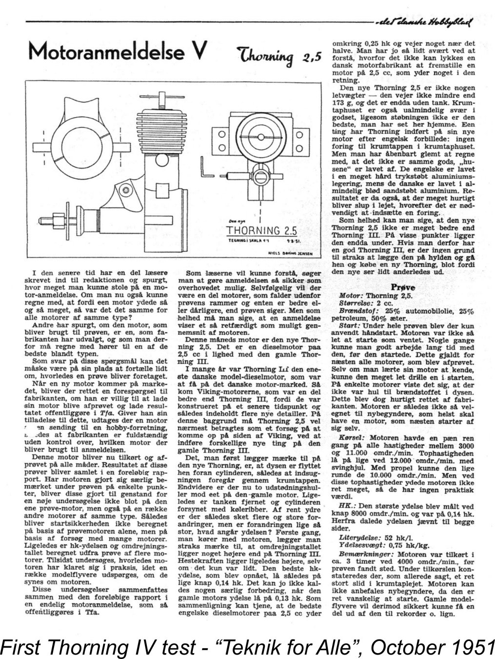
The Thorning 3.5 cc model actually beat the 2.5 into production, appearing on the Danish market in the latter part of 1950. A full analysis and test of this engine appears elsewhere on this website. The revised 2.5 cc FRV model seems to have hit the market a little later, in the first part of 1951. This model was the subject of another published test which appeared somewhat belatedly in the October 1951 issue of the Danish "Teknik for Alle" magazine. The writer of this test report expressed the quite logical belief that the appearance of this then-new FRV model represented an attempt by Thorning Bensen to meet the very serious domestic competition arising from the early 1950 appearance of the Viking 2.5 cc sideport model, which had demonstrated a superior performance to that of the old Thorning III along with a far lower weight and a more competitive price.
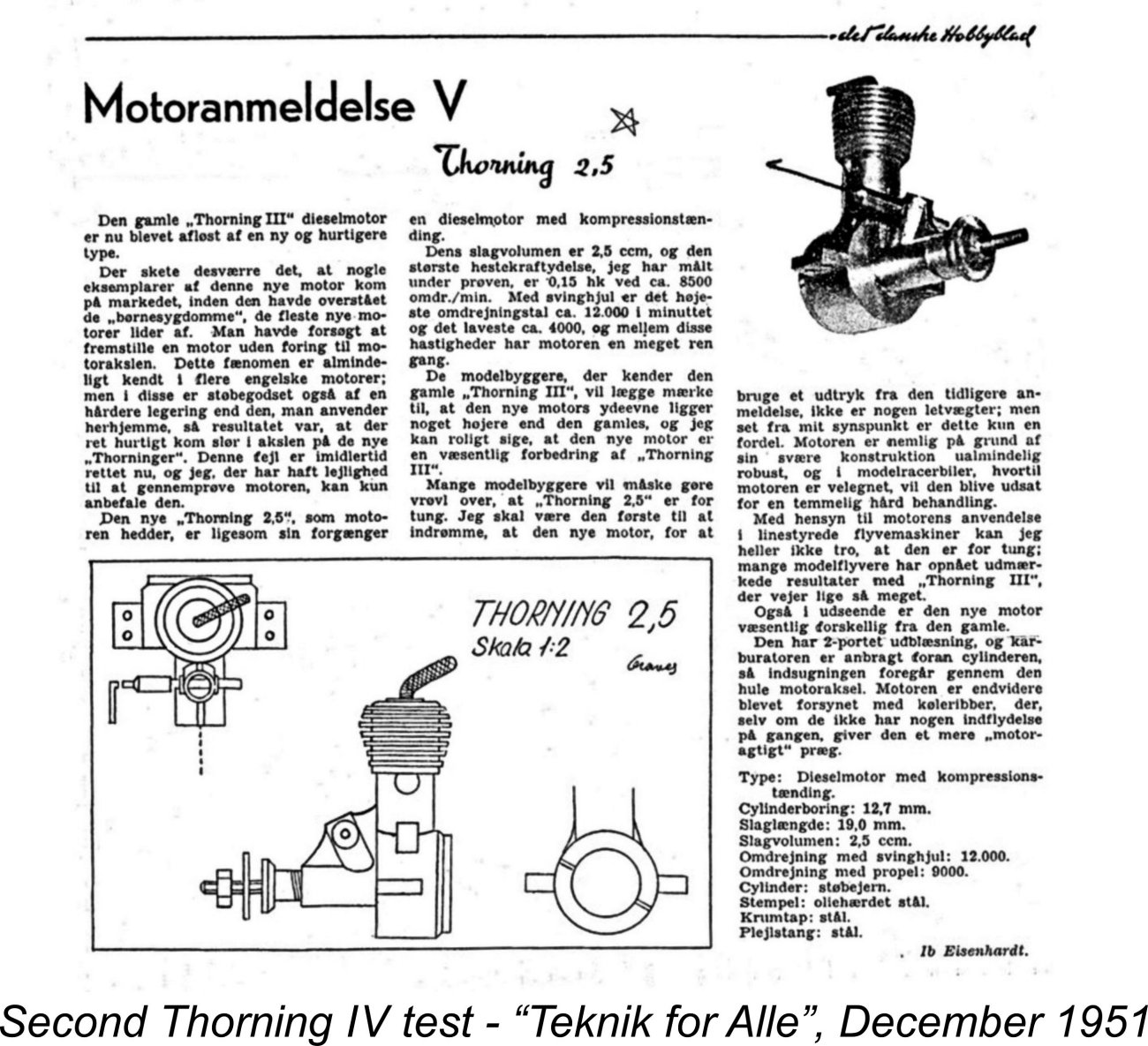
A specific factor which justifiably drew heavy criticism was the new Thorning 2.5’s use of a plain un-bushed main bearing. The writer acknowledged that this was accepted practise in England, but pointed out that the English engines used a relatively hard die-casting alloy for their crankcases, whereas that of the Thorning was cast from plain soft aluminium. As a result, the new Thorning’s main bearing developed very rapid wear, even during the running-in period. This had not been a problem with the Thorning III, which featured a bushed main bearing. The new model was found to be rather difficult to start, to the point where the writer didn’t consider it to be suitable for beginners. A specific issue in relation to this The tester’s final verdict was damning, to say the least. He expressed the view that the new model could not really be viewed as an improvement over the old Thorning III and was actually worse in certain respects (e.g., the main bearing). He went on to state that if one already had a good Thorning III there was no need to immediately put it on the shelf and rush out to buy a new Thorning 2.5 simply because the new model looked a little different! Harsh words indeed ……………. It would appear that Thorning Bensen must have heard these criticisms loud and clear and taken them very much to heart. He moved quickly to rectify some of the identified issues, most notably by incorporating a sleeve for the main bearing (and hopefully ensuring that all of his fuel jet holes were It’s clear that Bensen took care to make the staff of “Teknik for Alle” aware of his efforts. It’s equally clear that they were anxious to do what they could to assist a Danish manufacturer who was making honest efforts to improve, since a condensed re-test of the revised engine appeared in the December 1951 issue of the magazine (which was the final issue as far as I’m aware). The new report was far more favourable. The remedy applied to the main bearing was specifically highlighted. Moreover, a slightly improved output of 0.152 BHP @ 8,500 RPM was cited in this test report. Some serious low-end torque development there! My own testing has essentially confirmed these findings. A full independent review and test of the Thorning 2.5 model may be found elsewhere on this website. The improved model was now characterized as a “significant improvement” over the old Thorning III. In terms of power output, this was certainly true, although the quoted figures still fell well short of matching those recorded for contemporary 2.5 cc diesels from England and elsewhere.
It's worth recording to Bensen's great credit that he continued to offer repair and spare parts services for the Thorning engines for as long as the supply of spare parts held up. All parts were apparently gone by 1959, after which Bensen had no further involvement with model engines. He later took up painting and sculpture, becoming one of Denmark's more highly regarded artists. He died in 1987 at the age of 81. In closing our discussion of the Thorning 2.5 FRV model, it should be noted that this model has previously been referred to quite frequently as the Thorning V. Speaking strictly from my own personal viewpoint, I believe this to be an error arising from the fact that the Roman numeral V appeared prominently at the top of the two previously-mentioned and illustrated tests in "Teknik for Alle". In reality, that numeral referred to the fact that this was the fifth engine to be tested by the magazine. Both reports consistently referred to the engine itself as the Thorning 2.5, as did the manufacturer's advertising for the engine. I personally believe that to be the correct name. However, I'm well aware that not everyone agrees with me - you decide ............. In-depth reviews and tests of the Thorning 2.5 and Thorning 3.5 diesels may be found elsewhere on this website. Conclusion
However, time marches on and market conditions change. The arrival in Denmark of imported engines from places like Germany and England which offered higher levels of performance at competitive prices must have reduced demand for the “old fashioned” long stroke Thorning models. The domestic competition from Viking beginning in 1950 didn't help either. The only thing that could have saved the Thorning range in the face of this competition was the development of new designs offering higher levels of performance and quality at competitive prices. After the disaster of the premature release of the Thorning 2.5 FRV model, Thorning Bensen evidently decided that the rewards from small-scale model engine manufacture were insufficient to make such an effort worthwhile. Still, he had succeeded in creating a series of sports engines which seem to have served their owners well. Hence his was by no means a wasted effort. I hope that you’ve enjoyed this look at one of the most individualistic classic model diesels of them all. If you ever get a chance to experience one, I’m sure that you’ll enjoy the encounter! _______________________________ Article © Adrian C. Duncan, Coquitlam, BC, Canada First Published June 2016 |
||
 There are certain model engines that draw attention to themselves for no better reason than their unusual appearance! Such an engine is the central subject of this article - the Thorning III diesel from early post-WW2 Denmark. Please refrain from even thinking about Easter Bunny jokes, egg-head quips or egg-and-spoon races…………..and we guys with thinning hair will thank you to refrain from drawing any topside comparisons!
 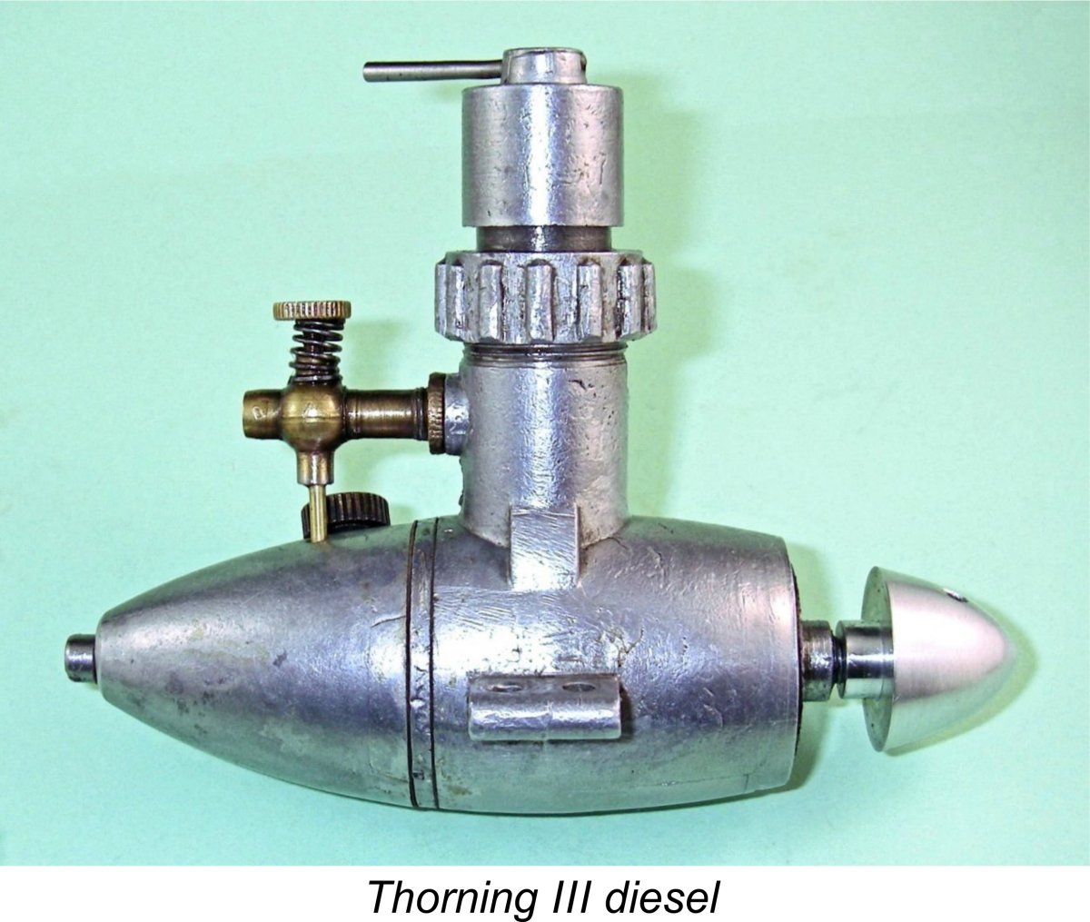 I must also acknowledge the much-appreciated assistance rendered by my Aussie mate Maris Dislers, who owns another example of the Thorning III. Maris was kind enough to share some test results and other observations which did much to inform this review.
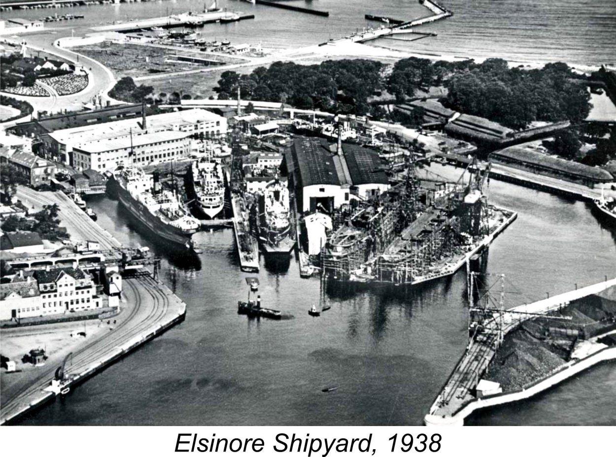 Thorning Bensen was born in 1906 and grew up to become a machinist. Prior to the latter part of 1945, Bensen was an employee of the Elsinore Shipyard at Helsingør (in English, Elsinore), a city in north-eastern Denmark lying on the coast some distance to the north of
 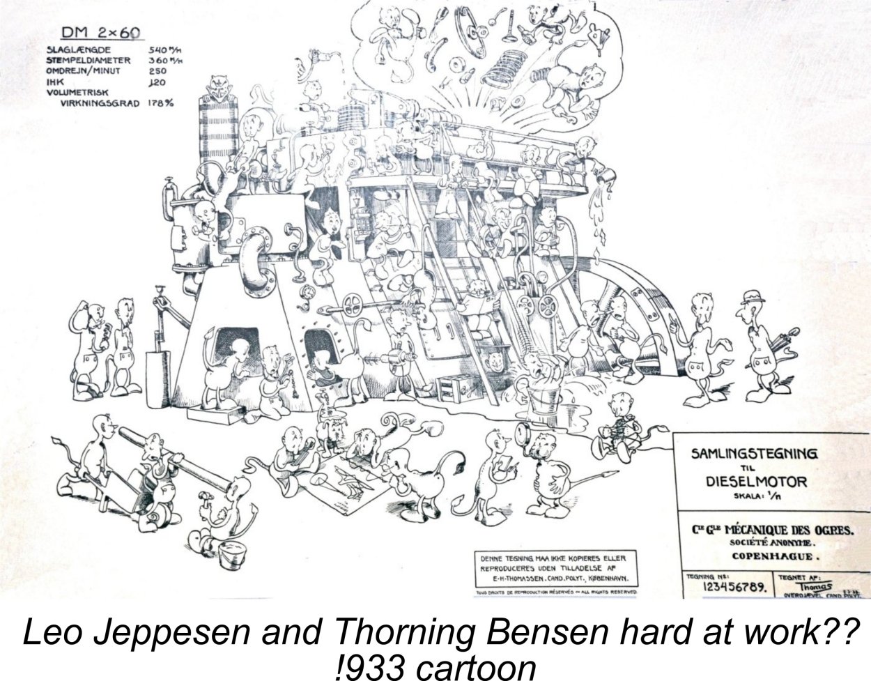 the accompanying cartoon depicting Danish marine engineers and mechanics hard at work building a full-sized marine diesel in 1933!
 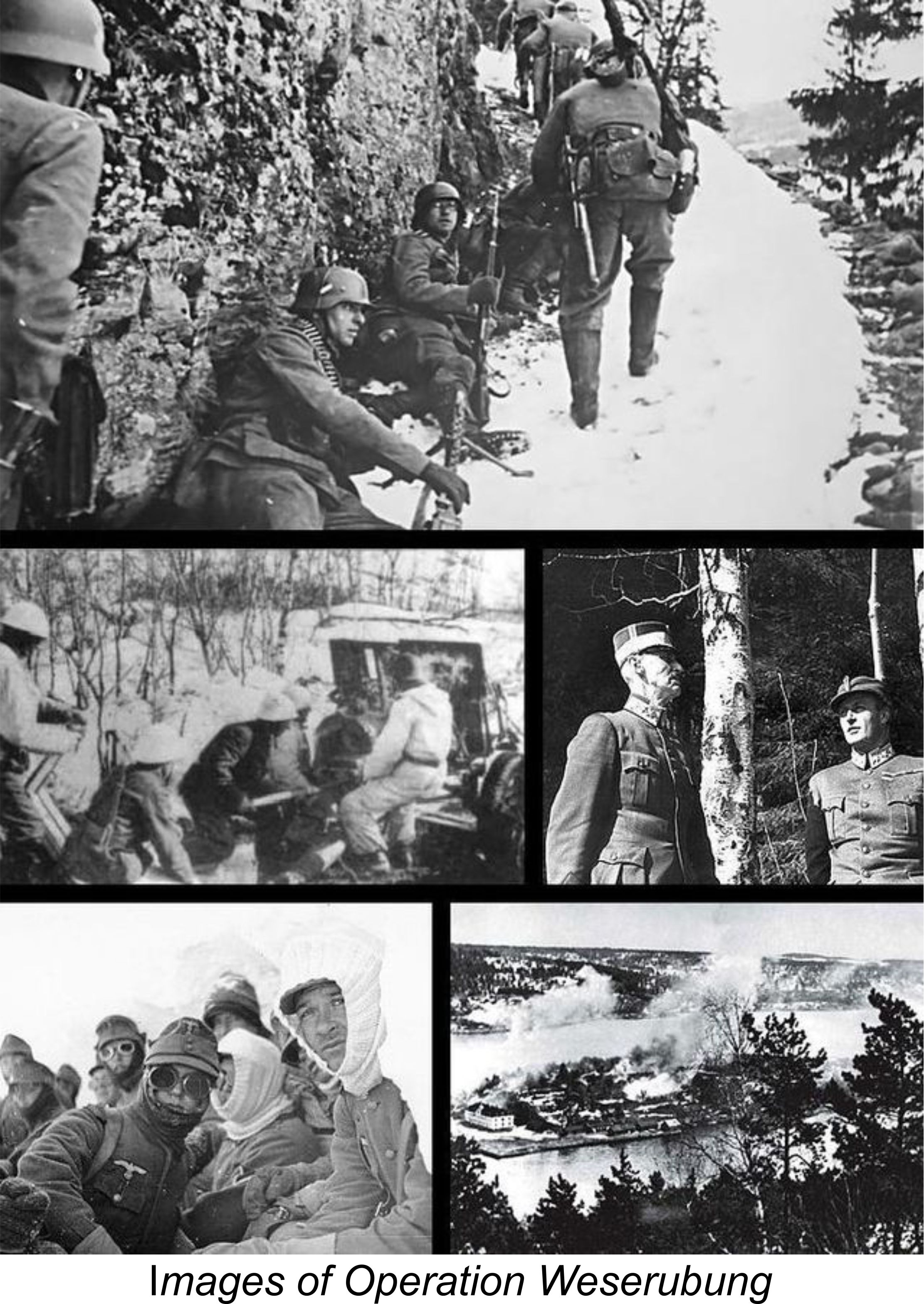 Although the early years of the occupation of Denmark had been relatively non-confrontational thanks to the efforts of the Government and the King, both of whom remained in the country, relations between the Nazis and the Danish people began to deteriorate in late 1942 as the tide of the war started to turn against Germany. By August 1943 the situation had become strained to the point at which the Germans made a number of extremely harsh demands to which the Danish Government was rightly unwilling to accede. This led to the German dismissal of the Danish Government on August 29
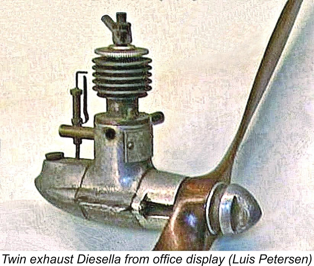
 Unfortunately, this prototype proved to be far from satisfactory in a number of respects. Back to the drawing board ........ a number of design changes were quickly developed to deal with the identified shortcomings. Once these changes were finalized, work resumed at the shipyard on the construction of several more prototypes which incorporated the identified improvements. As before, progress was limited by the availability of time and equipment, but by early June of 1945 the revised prototypes were finally ready. By this time, of course, WW2 had ended, along with the German occupation of Denmark.
 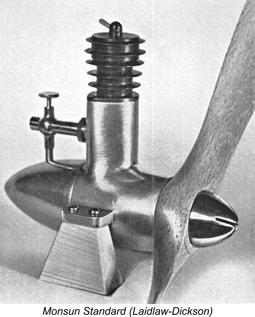 When one looks at the Monsun Standard beside its Diesella predecessor, one cannot fail to notice the marked similarities in styling. The cylinder designs differ, but the main castings and fuel tanks for the two models both combine to form the characteristic streamlined “egg” or “torpedo” shape which sets these engines very much apart. The shared use of a recessed prop driver with a streamlined spinner nut is also a notable similarity.
 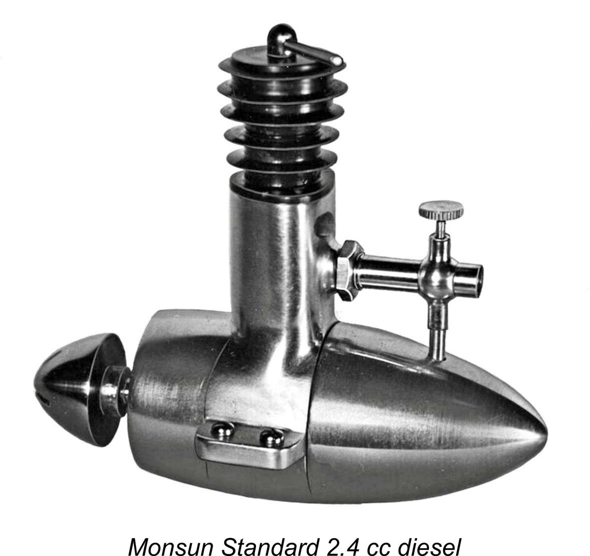 The porting used in this design was actually quite advanced for its day, with all of the ports clustered together at the rear. The rear exhaust was located immediately above the induction port, with twin bypass and transfer ports located one on each side in close proximity. Almost a rear-exhaust Schnüerle porting system, in fact, without the boost port! This arrangement will be made clear through a review of the article on this engine which may be found
 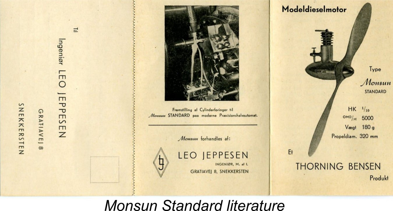 To facilitate this, a division of responsibilities took place at this point. Thorning Bensen focused solely upon the manufacture of the engines, while the marketing responsibilities fell upon Leo Jeppesen. In accordance with these arrangements, the promotional material for the engine specifically cited the engine as a Thorning Bensen product, but the stated business address for marketing purposes was that of Leo Jeppesen at Gratiavej 8 in Snekkersten, effectively a suburb of Helsingør lying a little to the south of the main city.
 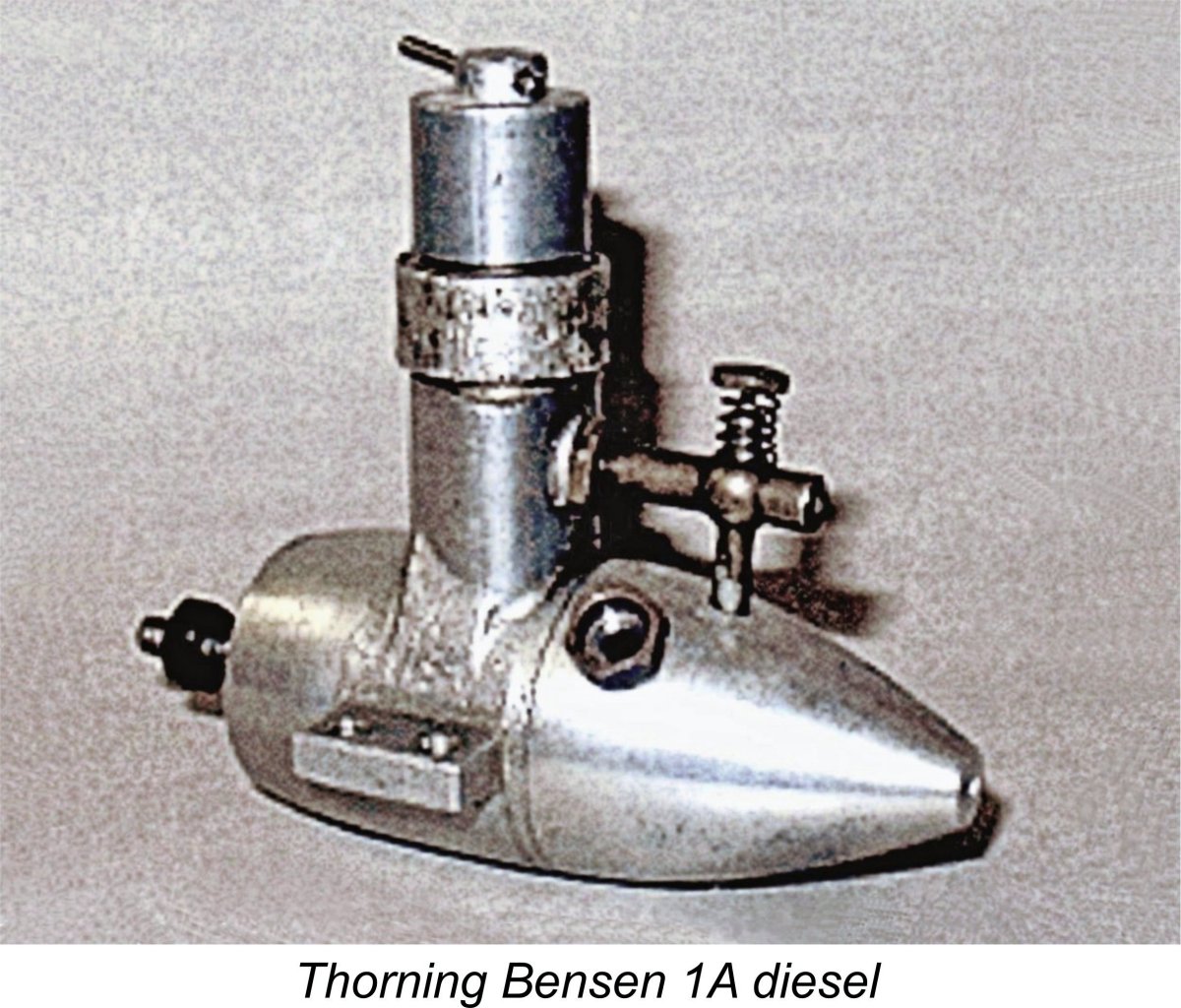 Despite Jeppesen’s departure, it appears that Jørgen Dommergaard continued to influence Bensen on design matters at this stage. As far as the issue of cooling fins was concerned, the second design to emerge from Thorning Bensen's workshop set the record straight with a vengeance! This was the Thorning Bensen 1A model of mid 1946, which had no cooling fins at all - Jørgen Dommergaard finally had his wish!
  Both the “dog collar” and the moving head compression adjustment features had previously appeared on the ground-breaking early 1944
 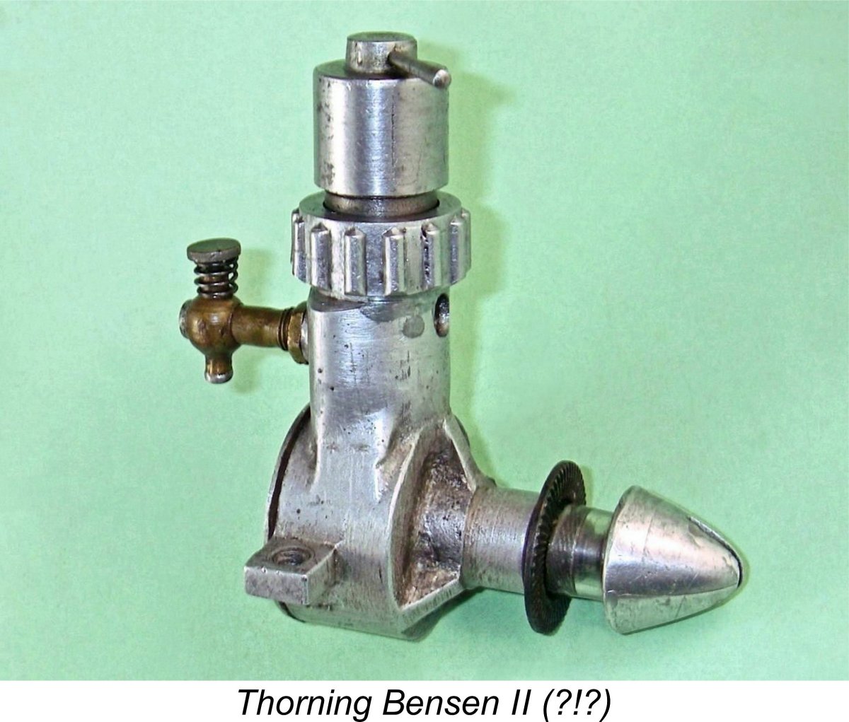 here. The 1A
 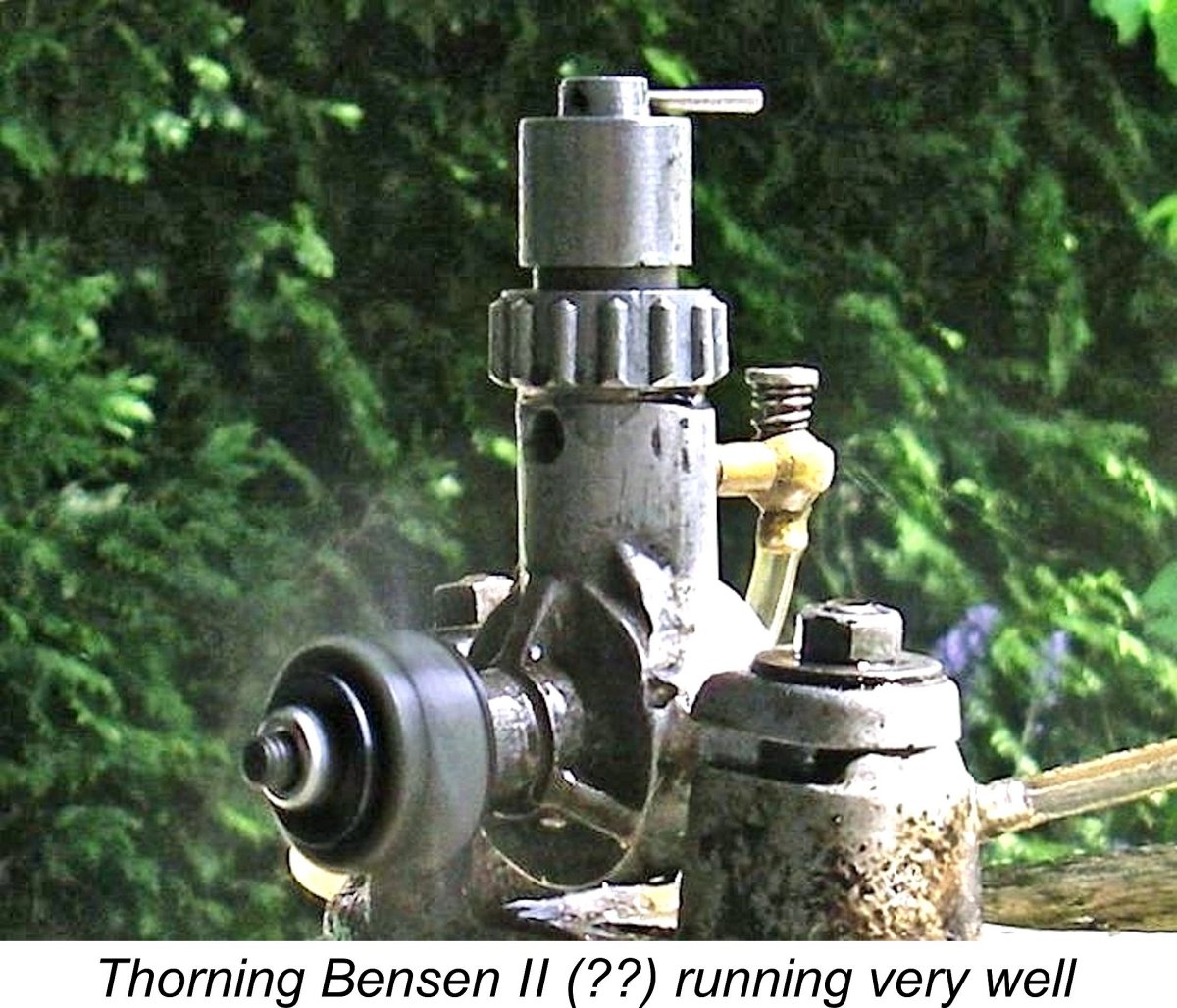 filed off for some obscure reason. This seems to have been done before the case was finished, since the evidence of filing has been very nicely homogenized into the wider surface finish of the case - you have to look very closely to detect the evidence. In addition, the two remaining mounting holes have both been tapped with some relatively coarse thread for which I have as yet been unable to find a matching tap or bolt.
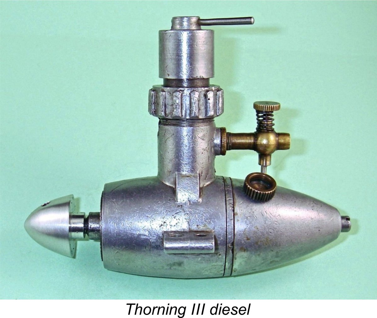
 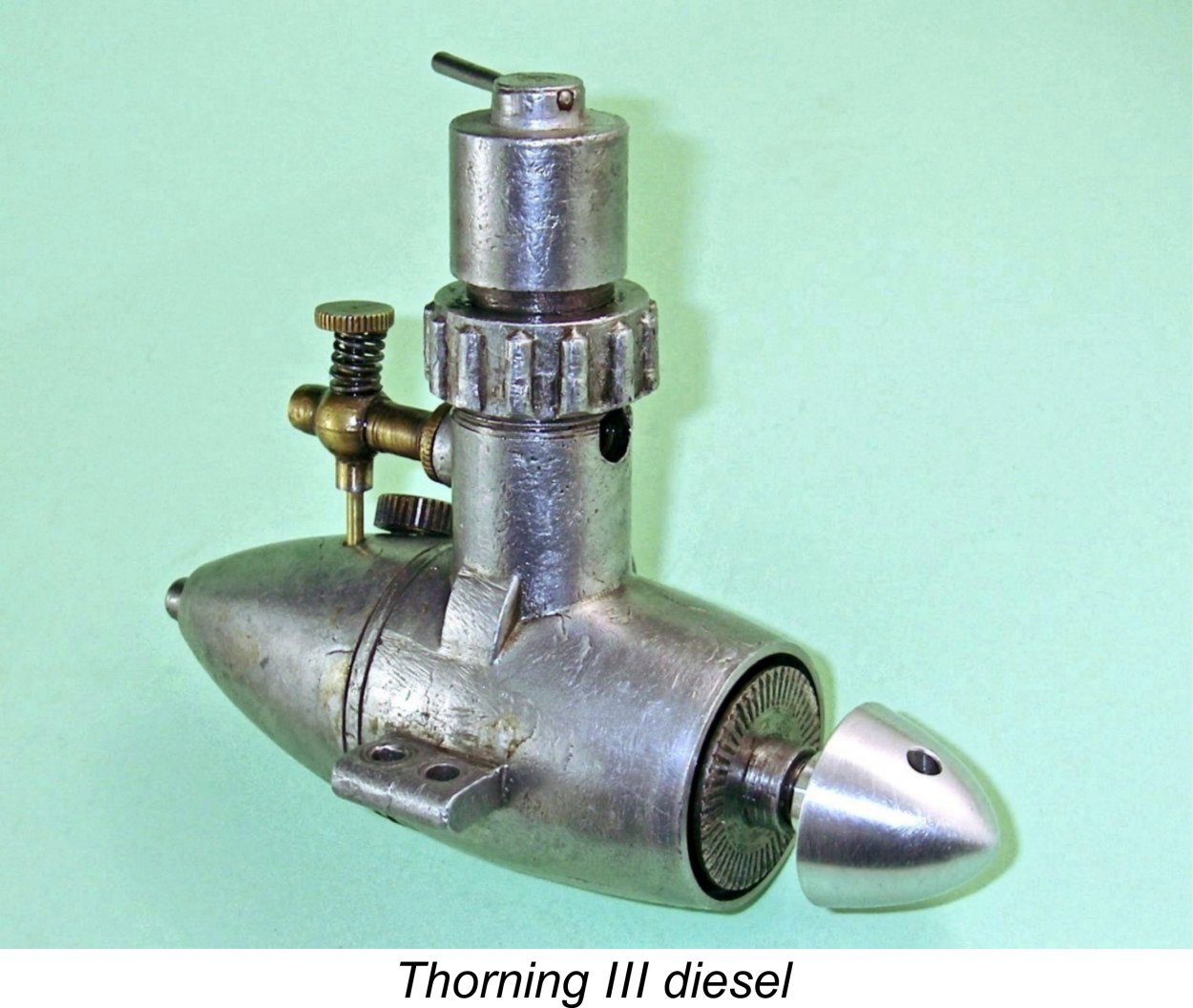 Like the earlier Monsun Standard and its Thorning Bensen 1A derivative, the Thorning III appeared on the outside to be a basically conventional long-stroke plain bearing sideport diesel of its era hiding beneath a highly unconventional external appearance! It continued the streamlined “egg” (or “torpedo”) styling which had been a feature of the Monsun Standard, the Thorning 1A and their Diesella predecessor. The spinner nut for prop mounting continued to be provide with a transverse slot (or in some cases two slots at right angles) to facilitate tightening. The spinner shown in the attached images of my example is my own reproduction having a more conventional (and more wear-resistant) cross-hole for a tommy bar.
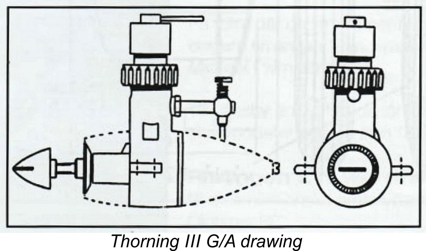
 A relatively minor change was the replacement of the machined "dog collar" cylinder retention ring of the Thorning Bensen 1A with a ribbed die-cast component. This undoubtedly afforded a superior purchase upon the ring for tightening purposes.
 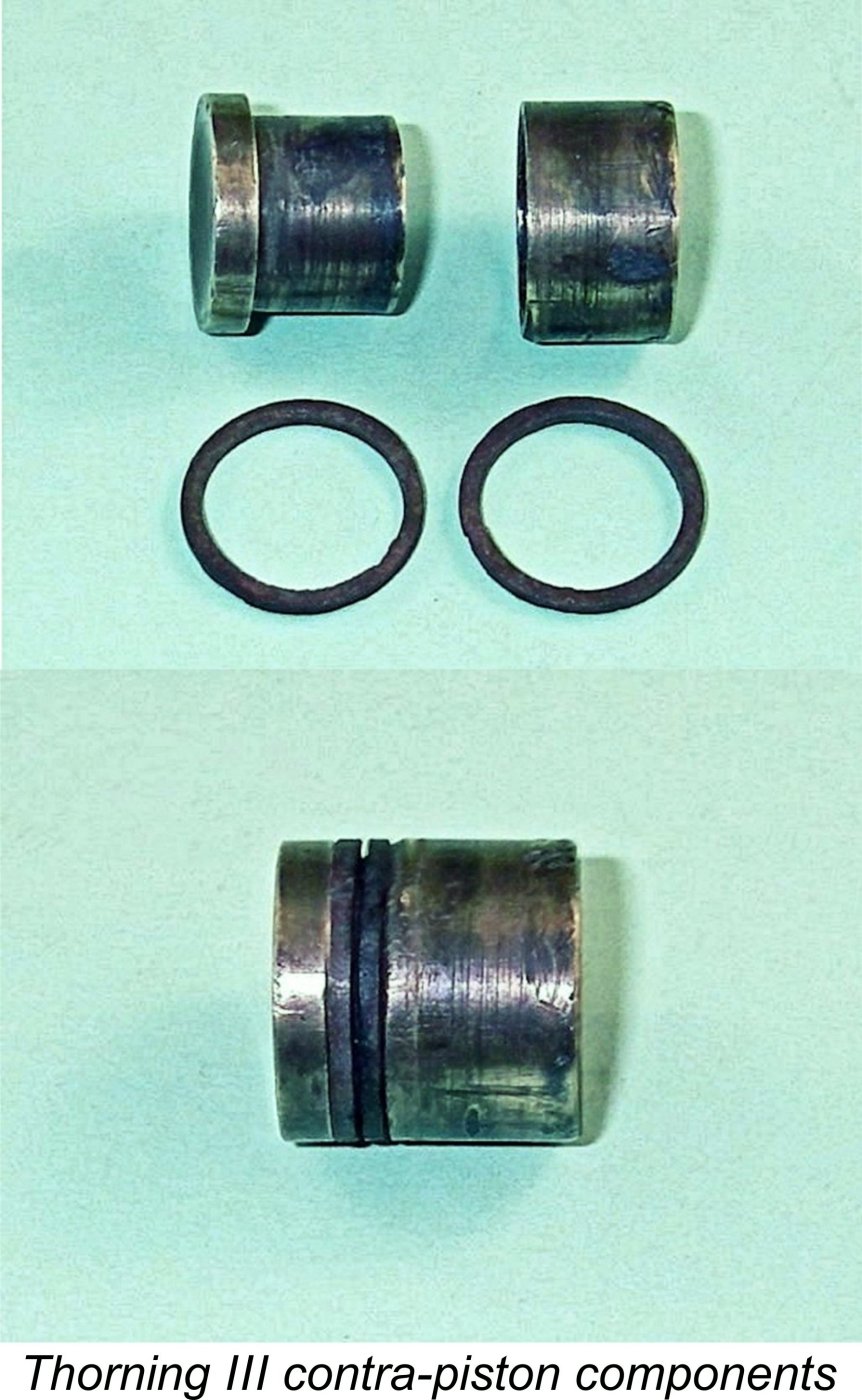 Another noteworthy feature was the contra piston. Rather unusually, this was made of brass. Even more unusually, it was a composite component which included a T-section internal element which presented its enlarged end to the combustion chamber. A length of graphite-impregnated yarn (or perhaps a leather washer) was wrapped around the inner component just above its "head", and the outer sleeve was then added, trapping the wrapping material and transforming it into what was in effect a resilient packing ring. The underside of the cylinder head bore against this outer sleeve, which stood proud above the stem of the T-section inner component when the yarn was in place.
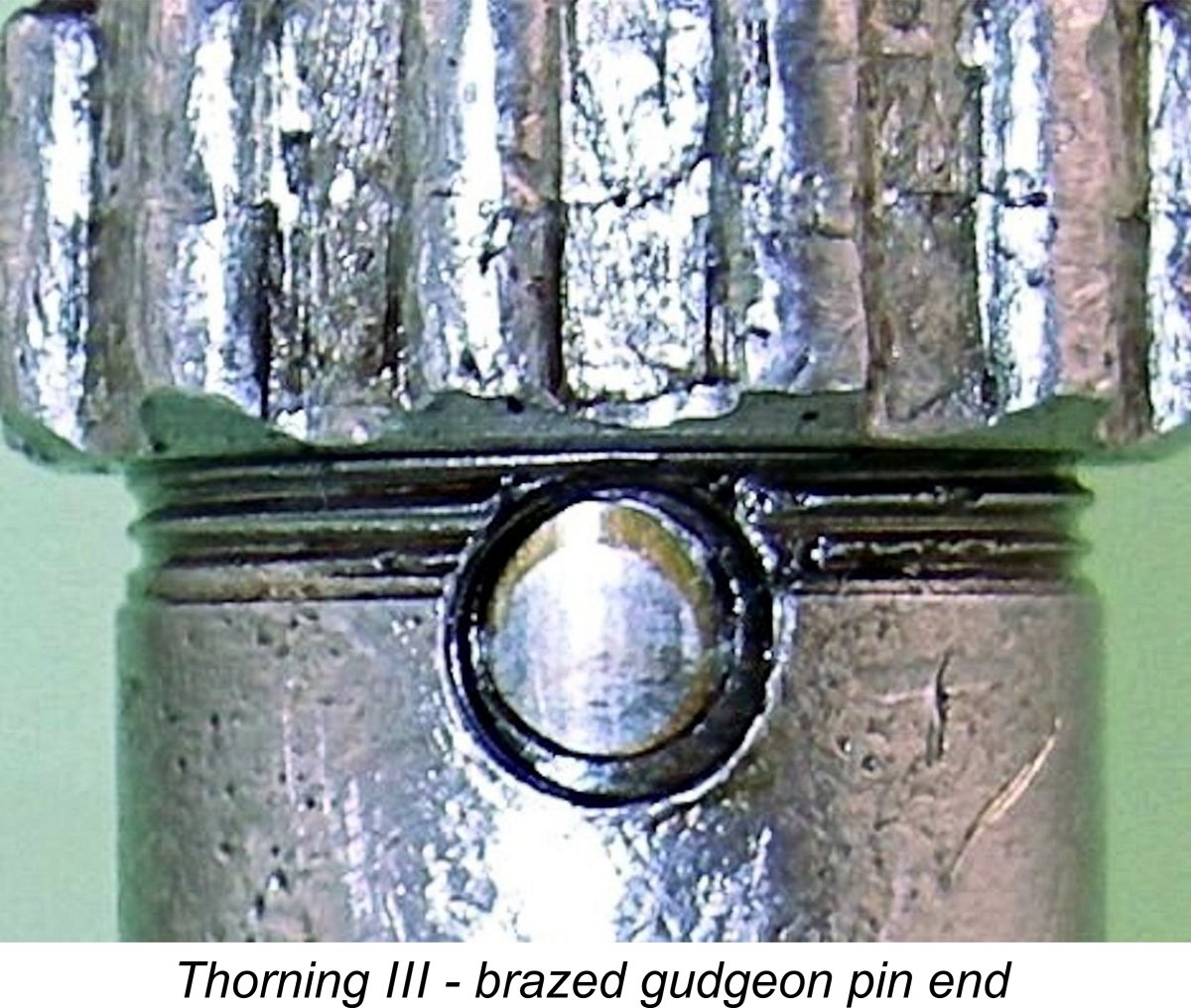 My example of the engine was suffering from a sloppy small-end fit on the steel con-rod. Upon investigation, I found that the piston-rod assembly was unique in my personal experience – the rod had been assembled onto the piston using a conventional gudgeon (wrist) pin, the ends of which had then been brazed into their piston bosses for security! Moreover, this had been done prior to the final lapping of the piston into the bore, since both the brazing material and the gudgeon pin ends formed part of a smooth unbroken working piston surface. The example owned by Maris Dislers is similarly constructed, so this is definitely a manufacturer-created arrangement.
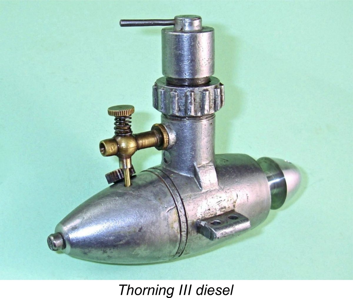 At the rear, induction was through a carburettor which was neatly machined from a brass casting. This component carried the externally-threaded needle and incorporated a surface jet located in a constriction of true venturi form, expanding on both sides. Needle tension was created by the used of a coil spring in the conventional manner.
 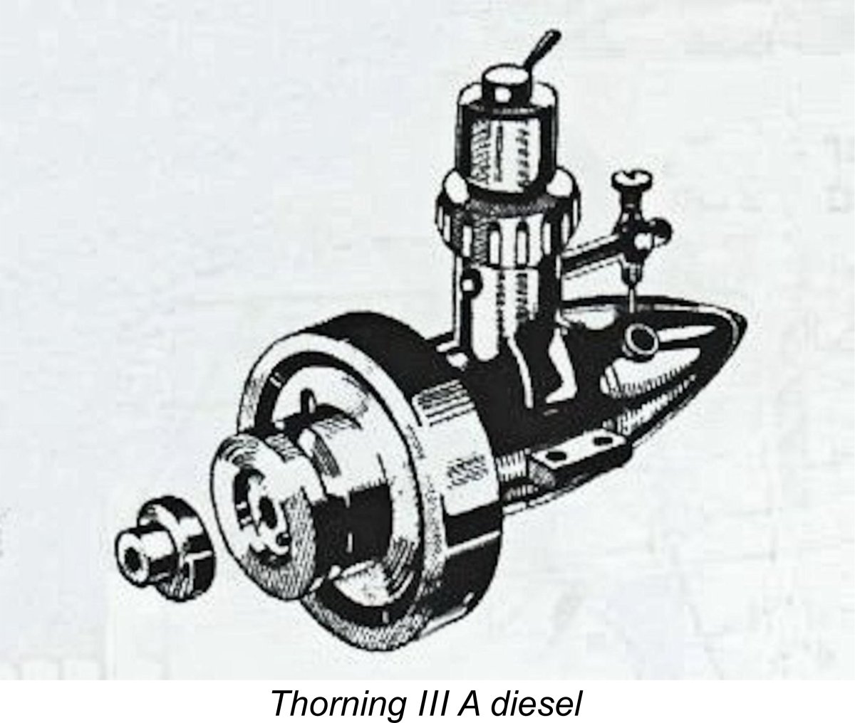 Reports from other owners of examples of this engine all agree with my own observation that it was generally very well made. It would appear that Bensen had overcome the factors which had led to the previously-noted deterioration of quality in the original Monsun Standard production series.
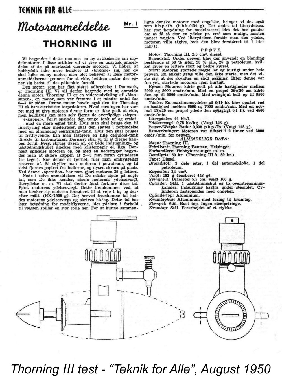 As far as I’m aware, the Thorning III has never previously been the subject of a published test in the English language. However, a Danish-language test report on the engine did appear in the August 1950 issue of the "Teknik for Alle" magazine, when the engine was still in production. This was in fact the first of a short series of engine test reports to appear in the magazine.
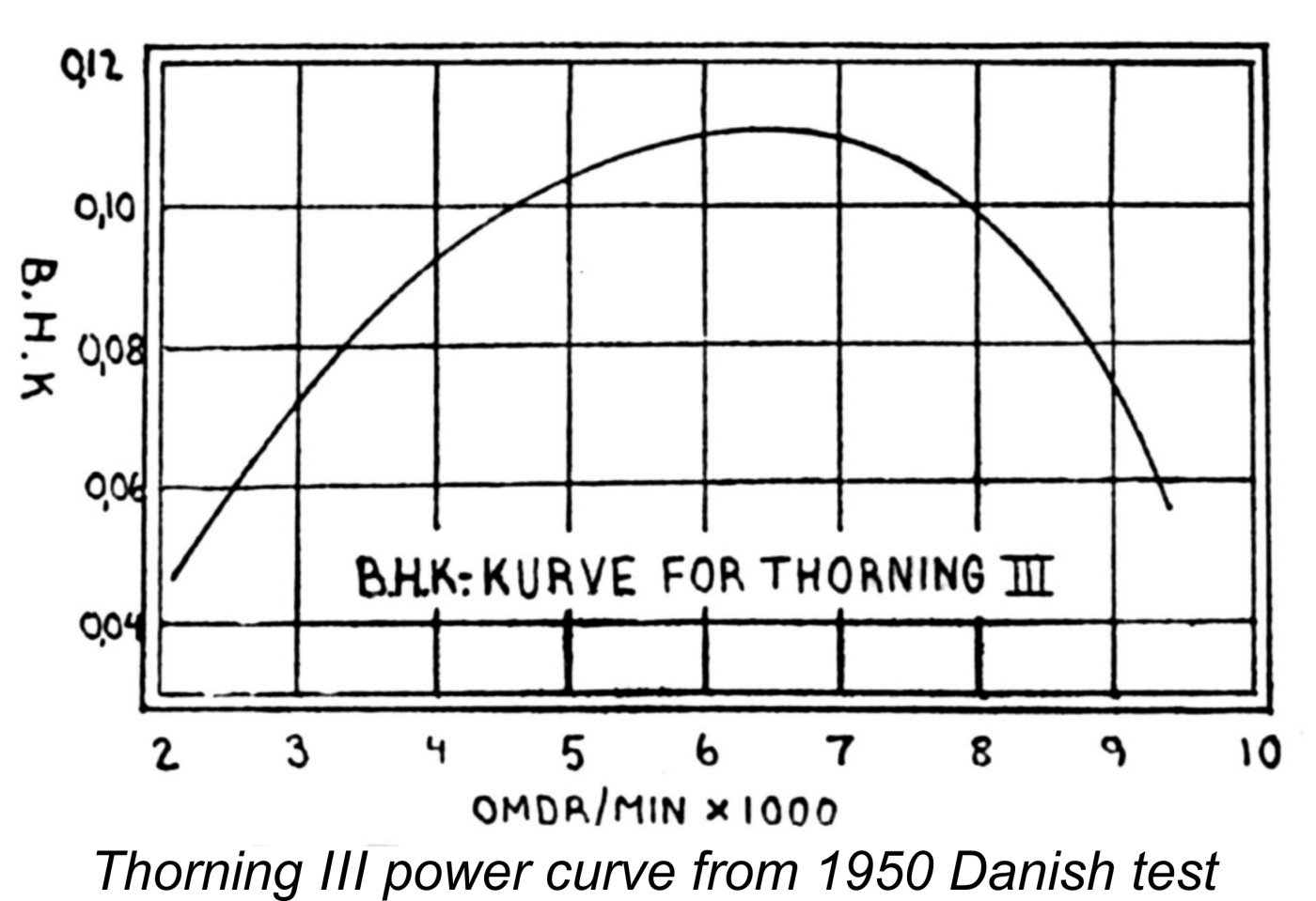 The report stated that the manufacturer’s recommended fuel for this engine was 60% ether, 20% kerosene and 20% castor oil. However, the tester found that a modified mixture of 50% ether, 25% kerosene and 25% motor oil gave easier starting and better running. Using this fuel, he found the engine very easy to start on all props tested, apart from one period of difficult starting which was traced to a leaking packing ring in the contra piston.
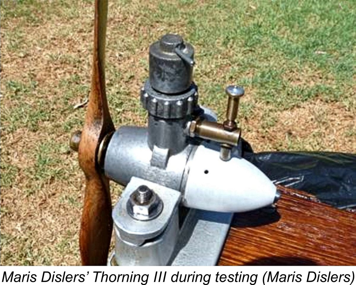 Maris Dislers reported that he had tested a few props on his example some time ago. His engine has a non-standard carburettor assembly but is otherwise functionally original. Measured speeds included 5,000 RPM on a Super Thrust 11x6, 6,100 RPM on a P.A.W. Trucut wood 10x6, 6,500 RPM on a Graupner Super GRP 10x4 and 6,800 RPM on a Tornado GRP 9x6. Based on power absorption coefficients for other similar props of comparable design, Maris came up with an admittedly rather rough estimate of around 0.090 BHP at just over 6,000 RPM.
 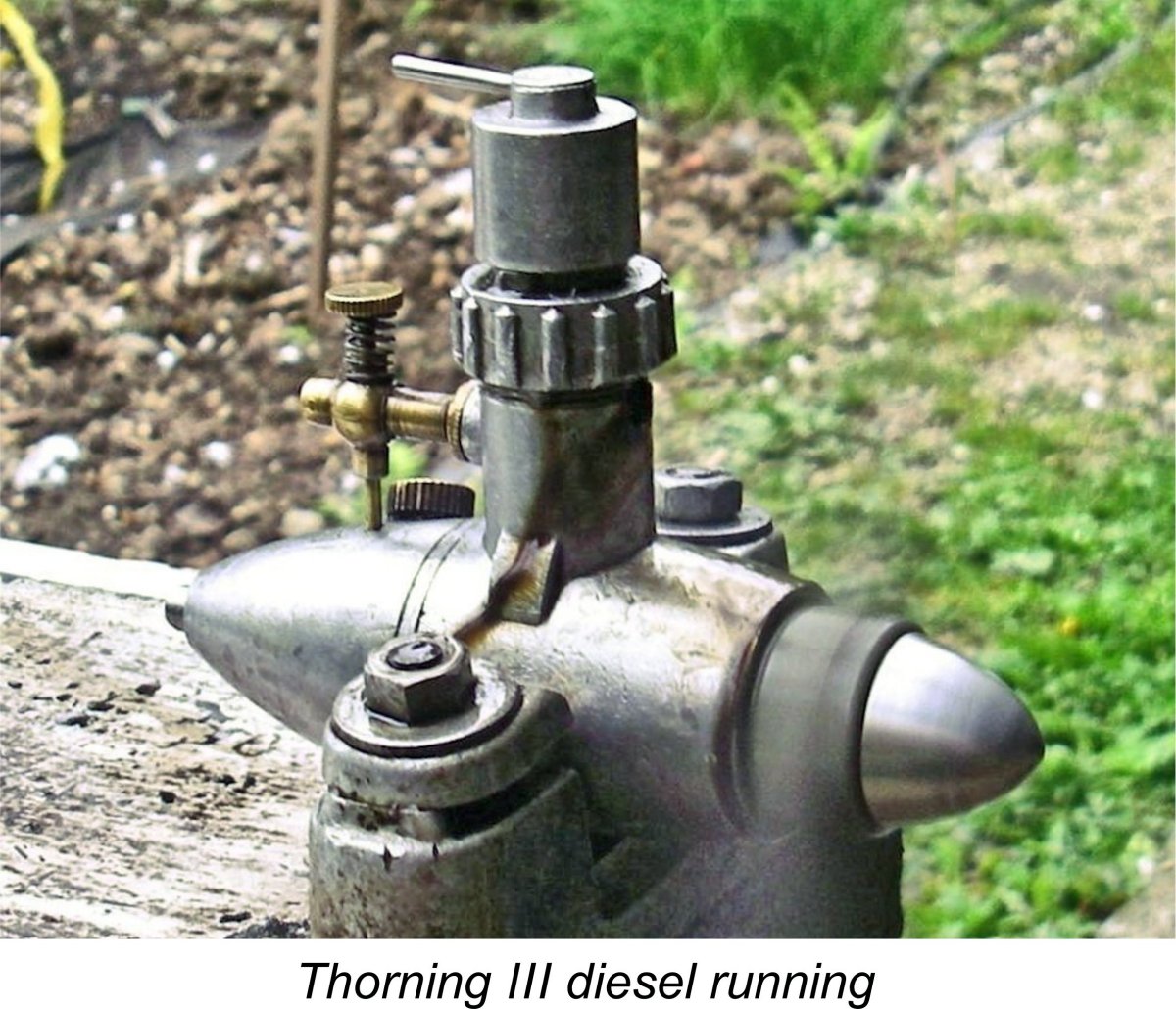 Having recently tested both the
  However, once the needle setting was established, the engine ran the tank out smoothly and cleanly. Thankfully it would start and run at the same needle setting, which eased the problem a good deal. As expected, the very large back tank proved to be well in excess of anything required for free flight model aircraft service – the engine seemed to run forever on a full tank. I suspect that most owners with model aircraft use in mind would have followed the advice of the “Teknik for Alle” tester by setting the original tank aside in favour of something more conveniently sized or configured. No doubt that's why so many surviving examples have lost their tanks.
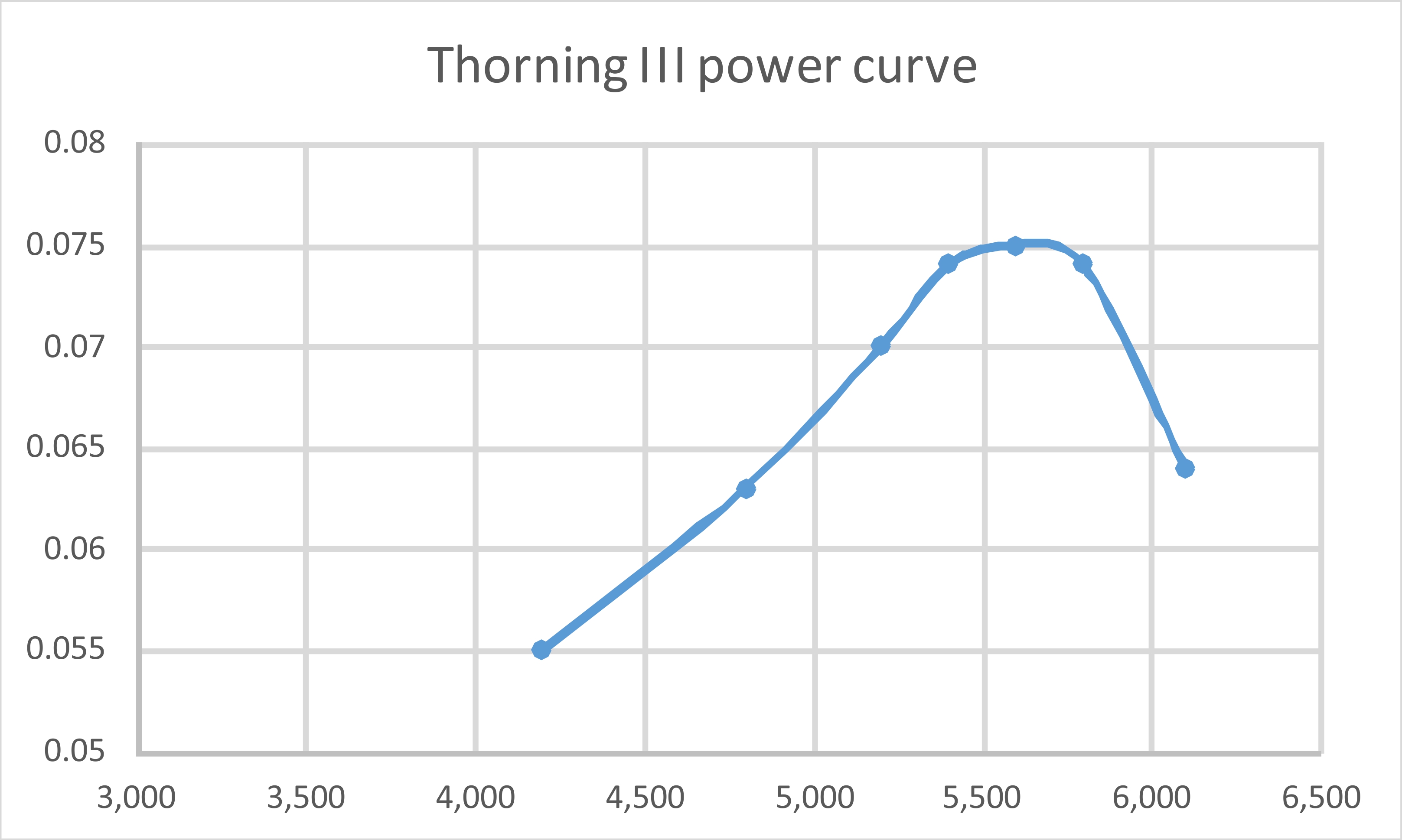
 In mid 1949 a new threat emerged. Word got around in Danish modelling circles that Christian Tommerup Clausen was consulting with members of the Odense Model Flying Club regarding the design of a 2.5 cc diesel that would represent very stiff domestic competition for the increasingly-venerable Thorning III. This model was destined to appear in early 1950 as the very successful
  This first 2.5 cc FRV prototype retained the "dog collar" cylinder attachment system of its sideport stable-mate. It also retained its companion’s bore and stroke measurements of 12.7 mm (0.500 in.) and 19 mm (0.748 in.) respectively for an identical displacement of 2.41 cc (0.147 cuin.).
 And by no means too soon! The new Viking 2.5 cc model duly appeared in early 1950 and proceeded to encroach mightily upon the market territory previously occupied by the Thorning III. It was both lighter and more powerful, also selling for an artificially low introductory price of only 27 kr. as opposed to the 59 kr. of the Thorning III. Although the price of the Viking was soon raised to a more economically rational 56 kr., there was no getting around the fact that the Thorning III was no longer in the hunt.
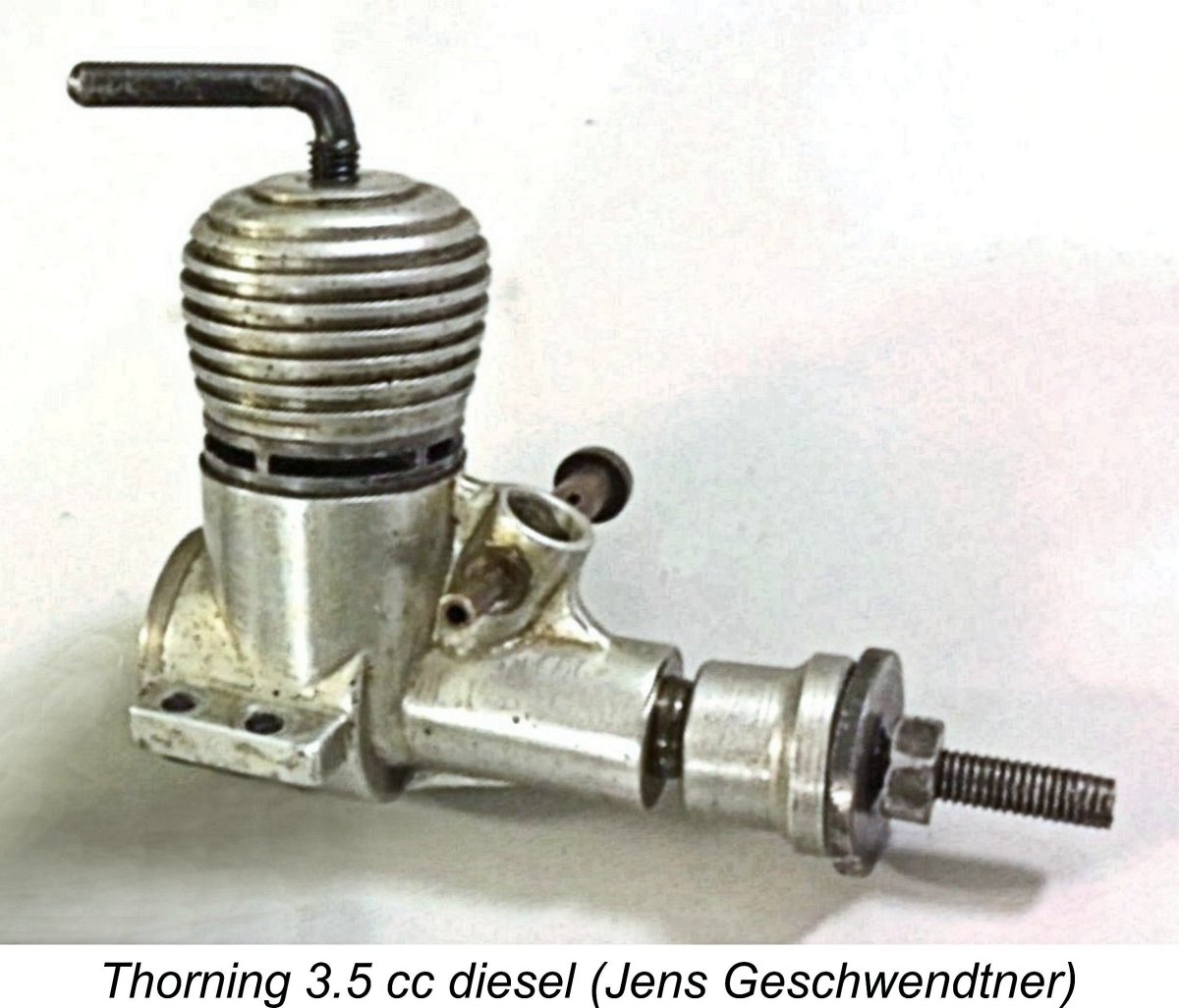
 This test is noteworthy insofar as it was rather openly and unexpectedly critical of this new product from an established Danish manufacturer. After explaining the way in which test examples of a given engine were obtained by the magazine free from any manufacturer influence, and after also outlining the magazine’s test procedures, the writer went on to compare the new Thorning rather unfavourably with typical contemporary English diesels, which were clearly seen in Denmark as the design yardstick by this time. He expressed disappointment at the Thorning 2.5’s rather modest measured output of 0.142 BHP @ 7,900 RPM along with frustration that Danish manufacturers seemed unable to develop 2.5 cc engines which came anywhere near matching the performance of the best English products.
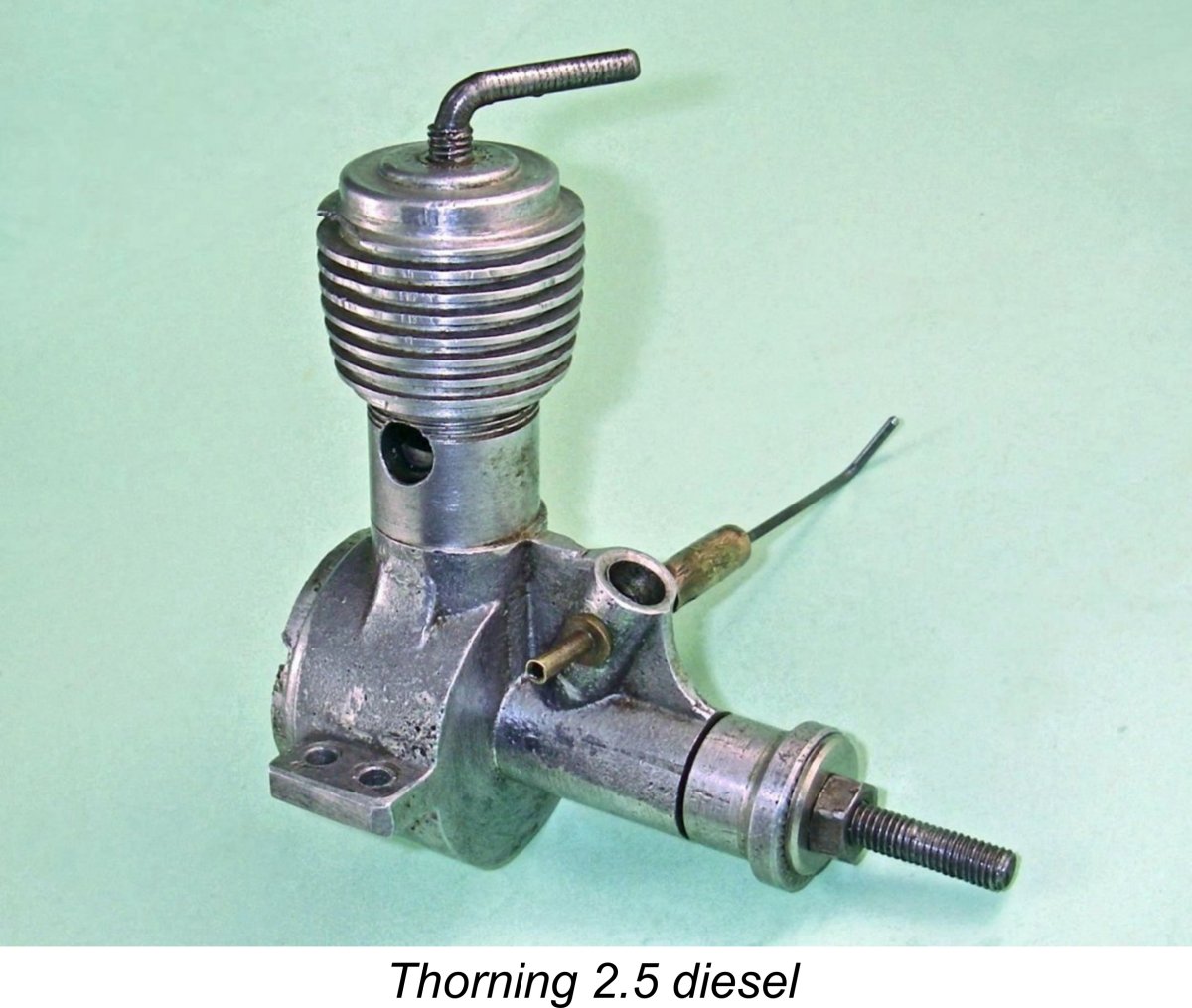
 In any case, the damage had already been done. About 500 examples of the Thorning 2.5 cc and 3.5 cc FRV models were produced in total, but these could not compete with the lighter and more powerful designs now available from the likes of Viking and various foreign manufacturers. By the end of 1951, after making a single prototype example of a pulse jet motor which never saw production, Thorning Bensen had ended all model engine manufacture, going instead into the business of making printing equipment for newspapers and magazines.
 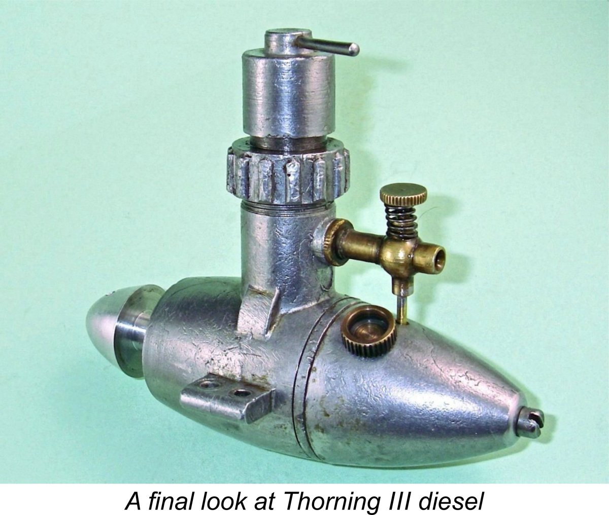 The engines produced by Thorning Bensen during the early post-war period, most notably the Thorning III and III A models, appear to have served their purpose admirably. They were well-made and dependable sports engines having no pretensions to stylistic elegance, flashy appearance or noteworthy levels of performance, but they did what many modellers required of them – they started easily, kept on running and powered functional model aircraft, boats and cars very effectively! For many people, that was enough.
| |