
|
|
Danske Model Motoren – Early Danish Model Engines and the Viking Range By Adrian Duncan and Luis Petersen
It was in fact my personal interest in the Viking engines that got this project started. My original intent was to confine myself to setting out the history of the Viking range. However, to do that I realized that I would need help from some knowledgeable individual(s) in Denmark. Immediately I thought of Danish team-race expert and multi World Championship engine builder/tuner Luis Petersen. I have published Luis’s work before in the form of his most interesting 1977 comparative test of a number of then-current (and now classic) team race diesels of the mid 1970’s. Recalling this article, I had little doubt that Luis would be the right guy to help out with the Viking project. When I first contacted Luis in early 2016 to see if he could assist me in the preparation of an article for this web-site covering the Viking engines, his initial response was to send me a copy of his own earlier Viking article which had originally appeared all of 26 years previously in a 1990 issue of the Danish modelling magazine “Modelflyvenyt” (issue 1990-1). Naturally, the original article was in Danish, a language with which I have no familiarity. However, Luis very kindly agreed to assist by providing a translation of the earlier article for my reference and editing. It’s hard for me to find the words to express my gratitude.
My good friend Lars Gustafsson from Sweden also got in on the act by providing scans of a number of Swedish advertisements for Danish engines, complete with English translations. This did much to inform my research into the penetration of Danish model engine ranges to other Scandinavian markets. Thanks, Lars!! All of this information was far too interesting to go unused, since it added a great deal of historical context to the Viking story. Consequently, I have elected to create a completely new article which combines Luis’s original 1990 Viking material with the additional information that he, Jens and Lars subsequently provided on other Danish model engine ranges from the pioneering era. Hence our examination of the Viking range will now be preceded by an overview of the early years of model engine manufacturing in Denmark leading up to the arrival of Viking on the scene. We hope that you enjoy the result of what turned out to be a most enjoyable collaboration! The following two sections of the article will cover respectively the early origins of the model diesel and the history of model engine manufacture in Denmark up to the point at which the Viking range first appeared. Readers who are already familiar with this material or whose interest is confined to the Viking range are advised to skip to the subsequent sections. Others, please read on!! Background
Some ten years later, Thalheim went into production with a series of model engines which were marketed from 1938 onwards under the ETHA label, derived of course from Thalheim’s name rather than from an English rendition of a primary ingredient of the engine’s fuel! These appear to have been the world’s first commercially-produced model diesel engines. It’s a bit of a mystery why it took Thalheim ten years to actually begin to capitalize upon his patent …..... most likely the Great Depression which began in 1929 had something to do with delaying his market entry until 1938. Maris Dislers' review and test of the replica ETHA 1 diesel by Richard Gron may be found elsewhere on this website.
Be that as it may, by the end of 1937 Eisfeld had built a successful prototype having a displacement of 15 cc (0.915 cuin.). This engine ran on a fixed 22:1 compression ratio and was equipped with a high-pressure injection pump and a needle injector. When properly adjusted, it apparently ran very well on regular full-sized diesel fuel. A promising start, but further development of this remarkable engine was halted in view of the far greater ease of manufacture and superior dependability of the conventional spark ignition engines of that time. Even so, following the onset of war in 1939 and working in collaboration with A. Thusius (who went on to produce model diesels under his own name), Eisfeld did resume his model diesel experiments, citing his reasons for doing so as the unreliability of the miniature accumulators then available as well as the problematic availability of dry batteries under wartime conditions. Eventually in 1942 he produced an amazing and successful 3.7 cc (0.225 cuin.) injector-equipped true diesel prototype suitable for model aircraft. Reportedly this unit weighed no more than a comparable spark ignition model with its ignition support equipment. Its compression ratio was a daunting 23:1 - starting must have been fun!
The Eisfeld model diesels were produced in a range of displacements from 0.5 cc all the way up to 10 cc. All of these models were made to a common basic design. A considerable number were manufactured for use by the Hitler Youth organization in promoting air-mindedness among its members. Production of these well-designed and finely-made engines continued for some time after the war. Several examples found their way to Britain, where they were highly regarded by Col. C. E. Bowden and others. In passing, it seems worth commenting upon the surprising degree to which model diesel experimentation and manuacture continued in Germany well into the wartime period. Names like Eisfeld, Kratmo, Kemmerling, Thusius and Mack-Madie come immediately to mind, and there may have been others. According to Col. Bowden, even the famed Mercedes automobile company got into the act by making a high-quality one-off model diesel engine for none other than former WW1 aviator Hermann Goering! Quite a contrast to the situation in wartime Britain, where model diesel experimentation had to await the conclusion of the conflict before really getting off the ground. Despite its later prominence in the field of model diesel design and production, Britain was very much a Johnny-come-lately in this field.
The technological success of the ETHA engines naturally inspired others to have a go for themselves. The Dyno 2 cc model manufactured in Switzerland by Klemenz-Schenk (whose main business was the manufacture of bicycle lighting dynamos, hence the engine's name) was one of the earliest spin-off products, being developed between 1938 and 1940 and making its market debut in 1941. It was a considerable step forward from the ETHA designs, being both smaller and lighter as well as having a higher specific power output. As time went on, the Dyno became one of the most widely-imitated early model diesel designs of them all, as we shall see. Peter Scott has quite credibly noted that the number of surviving Dyno copies and clones doubtless exceeds the number of originals by a considerable margin!
News of the new technology also reached neutral Sweden in 1942, along with an actual example of the Dyno 2 cc engine which somehow crossed war-torn Europe to come into the possession of Gunnar Fahlnäs, then the editor of the popular Swedish technical magazine “Teknik för Alla”, which was widely circulated in all of the Scandinavian countries. Impressed with the performance of his Dyno, Fahlnäs Ivan Rogstadius was soon followed by other Swedish model diesel experimenters. I’ve recounted the story of one of my personal favourites, the improbably-named Swedish Jack-of-all-trades Giancarlo Pinotti, in yet another article to be found on this website. There was also the 1944 Västeråsdieseln 2 cc model produced by the Västerås-based Johansson brothers, which was the precursor of the Komet range which will be the subject of another detailed article to appear on this site in due course. In addition, the prominent Swedish model dealer Hobbycirklarna of Finally, in 1944 the Stockholm model supply house of Svedfeld & Co. began advertising a model diesel which bore a striking resemblance to the Rogstadius design. Although this was apparently referred to by Svedfeld as the “Typhoon” model, the illustration which accompanied the advertisement bears the unmistakable Rogstadius stamp, also bearing an uncanny resemblance to the early Danish Mikro diesel, of which more in the following section. Despite the fact that both Norway and Denmark were under German occupation at this time, some information regarding model engine developments in other countries was sporadically available to enthusiasts in those countries from German, Swedish and Swiss sources. In Norway, Jan David-Andersen first became aware of the application of compression ignition to model engines in 1943, most probably from his reading of Ivan Rogstadius’s 1943 articles in “Teknik för Alla”, which remained in publication throughout the war and was read throughout Scandinavia. I’ve documented the David-Andersen story in yet another separate article to be found on this website. Another pioneering Norwegian model engine maker was Øivind Andersen (no relation), who was actually the first series producer of model engines in Norway, albeit on a very small scale. His story is included in the above-referenced article about Jan David-Andersen. Pioneering Developments in Denmark
Contrary to the situation in many other countries under German occupation, Denmark was initially viewed by the Germans as a neutral protectorate rather than as a conquered hostile nation. Consequently, most Danish institutions continued to function relatively normally until the summer of 1943. Unlike the situation in Norway, both the Danish Government and the King remained in the country in an attempt to protect the Danish people by somehow maintaining an uneasy working relationship between democratic and totalitarian systems. However, this proved to be impossible in the longer term, since the Danish population became increasingly hostile to the occupying power, particularly after the tide of the war began to turn against Germany in 1942. The final straw was an August 1943 demand by the Germans that (among other things) the death penalty be instituted for Danish actions judged by the Germans to constitute sabotage. Understandably, the Danish government refused to co-operate with this and other hard-line demands. Consequently, on August 29th 1943 the Germans officially dissolved the Danish government and instituted martial law. Thenceforth Denmark was treated by the Germans as a hostile occupied country. An early consequence was the German attempt to round up Danish Jews beginning in October 1943. Thankfully, most of the Danish Jewish population (around 7,000 in all) eluded this round-up and were secretly relocated to Sweden by sea during the following months.
An example of one of these units is pictured at the left. This very well-made example is one of a few such engines which were constructed by employees at the Danish Marine Workshop on the basis of Ivan Rogstadius's plans. When the subject of commercially-produced Danish model engines comes up nowadays, most people from outside Denmark immediately think of the Viking range and stop there. However, the Viking engines were actually relative late-comers. The fact is that Denmark was as well supplied as any other country with a Although a few model engines may have been individually constructed in Denmark during the early to mid 1930’s, the country’s first documented commercial-scale model engine manufacturer appears to have been Carl Rose, who had a pre-war hobby supply business called Modelmateriale located in Tarm on Denmark’s west coast. Rose entered the model engine field prior to the outbreak of war with a series of spark ignition models which first appeared in 1938. He went on to By the outbreak of war, Rose had reportedly sold some 200 CEROS model spark ignition engines having displacements ranging from 4 cc to 10 cc. When the supply of miniature spark plugs dried up following the outbreak of WW2 and the subsequent German occupation of Denmark, Rose began experimenting with model diesels, reportedly making his first such engine in 1940. However, he does not appear to have followed up on this concept until some time after the war, leaving the field open for others in the interim. It seems worth mentioning that an example of Rose's very first model diesel from 1940 was still retained at the CEROS factory when it was visited in the winter of 1950/51 by staff of the Danish modelling magazine "Teknik for Alle". The engine had clearly seen a lot of use, because it had reportedly accumulated over 100 running hours by that time. According to the writer of the report on this visit, which appeared in the February 1951 issue of the magazine, this engine remained in perfect condition despite all this running. In 1946, following the conclusion of WW2, Rose established a small precision engineering business in premises located at Håbets Allé 10 in Brønshøj, a suburb of Copenhagen. The primary business of his new operation was apparently the manufacture of precision mechanical components for the radio industry. However, model engines were in Rose's blood, and a proportion of the company's equipment and human resources continued to be applied to the small-scale production of model engines on the side.
Soon after the 4.9 cc glow-plug model appeared, Rose returned to the diesel fold. He did so by developing a neat and compact 3.5 cc crankshaft front rotary valve (FRV) diesel model, which turned out to be the final CEROS product, at least by that name. This engine appeared in the winter of 1950/51 but did not remain long in production, surviving for only a year or two at most. It bore a striking resemblance both in design and appearance to the contemporary AMCO 3.5 PB model from England. A full review and test of both the CEROS 4.9 cc glow-plug model and the CEROS 3.5 cc diesel will appear on this website in due course. Although they were manufactured in relatively small quantities, the CEROS engines acquired a good reputation among Danish modellers - note the CEROS advertisement in the previously-reproduced photo of the Kastrup tether car track. At the present time, I am unable to state with any authority exactly when CEROS model engine production ended, but they seem to have disappeared from the marketplace by the mid 1950's. A separate article covering the CEROS engines in greater detail will appear in due course on this web-site.
Although the actual manufacturer of the Jaguar 2.5 BB was not named in Truedsson’s catalogue entry, there is some evidence that Carl Rose may have been responsible for this engine. The CEROS 3.5 cc diesel model mentioned above had a very similar cylinder porting arrangement. Moreover, Luis Petersen has found a reference to Rose having made a limited number of smaller units (i.e., less than 3.5 cc) specifically for team racing. It seems not unlikely that the Jaguar 2.5 BB was that very engine. If any reader can confirm this possibility, please get in touch!
At that point in time, Eli Andersen (then aged 28 years) established a small workshop in the town of Kolding, applying the Diesella trade-name to the engines which were manufactured there by himself and Jeppesen. The fledgling Diesella company was located in a tiny workshop on Sydbanegade which According to the previously-noted January 1944 “Flyv” article, the Diesella 2.5 cc model entered production in November 1943. This almost certainly made it the first model diesel to enter commercial production not only in Denmark but in any Scandinavian country, since Sweden’s first commercially manufactured diesel, the Pinotti GP 1.5 cc model, did not enter series production until early 1944, while Norway’s first series manufacturer Øivind Andersen (no relation) did not enter the market until a little later in 1944. The fact that Eli Andersen saw commercial potential in the introduction of a model diesel at this time (after the German crack-down of late August 1943, remember) is significant in that it clearly indicates the existence in Denmark of a ready market for such products even under increasingly harsh wartime conditions. This in turn implies that aeromodelling remained alive and well despite the progressively more difficult conditions of the occupation. Perhaps some members of the German occupation forces were themselves potential customers. It would be interesting to learn the extent (if any) to which genuinely interested members of the German occupation forces (of whom there were doubtless many) were accepted as fellow model enthusiasts rather than as mere armed interlopers in occupied countries such as Denmark and France, to name but two. The perceived strength of the market which existed at this time is underscored by the fact that Eli Andersen felt able to set the price of the Diesella at no less than 115 Danish krone (kr., or DDK). To put this in perspective, Luis Petersen tells us that in 1940 one could rent a 3 room flat in Denmark for 85 kr./month!!
While retaining a certain degree of Dyno influence, the Diesella embodied a number of original design features and was considerably “prettied up”. A notable feature was its massive streamlined main bearing housing which featured a recessed prop driver along with a ball race crankshaft. The engine's styling was complemented by a nicely streamlined metal fuel tank at the rear. The visual effect which this streamlining created was quite pleasing. The engine was also distinguished by having a single exhaust port discharging through a tubular stack on the right hand side of the upper crankcase. That said, some Reported bore and stroke measurements of this engine were 13 mm and 18 mm respectively for a nominal displacement of 2.39 cc. Although it is generally (and correctly) referred to as a 2.4 cc unit, the manufacturer’s identification plate claimed that this model had a displacement of a full 2.5 cc. No need to split hairs, one supposes! The engine reportedly weighed in at a fairly healthy 200 gm (7.06 ounces) ready to fly. Cited output was 1/6 BHP @ 4,500 rpm. If accurate, this figure implied a pretty serious level of low-end torque development! Personally, I suspect a little exaggeration here ............... The Diesella engines were reputedly very well made. However, their further development stagnated after the war as Eli Andersen became interested in expanding the scope of the business during the early post-war period. Consequently, it appears that only some 200 examples of the Diesella 2.4 cc model diesel ended up being manufactured, making it an extremely rare engine today. As with most other Danish model engines at this time, many of these units were equipped with flywheels for car or boat use. A few examples seem to have been converted to glow-plug operation at a later date.
The Andersens had long had an interest in autocycles, going back in Eli’s case to 1927 when he constructed his first such vehicle at the tender age of 12 years using an old motorcycle engine, a used pram wheel and a drive belt “borrowed” from the coffee grinding mill in his father’s grocery store in Lunderskov! Once established in their enlarged premises, the Andersen brothers’ attention soon switched to this line of business, which appeared commercially promising due to the fact that one needed a permit to buy a car in post-war Denmark. Such permits were difficult to get, making the autocycle (knallert) or moped an attractive and affordable transportation alternative in a country with relatively few serious hills. The Diesella company was in fact destined to become best known for its involvement in the autocycle and moped business. One of its first products in that line was a 50 cc two-stroke engine which could be mounted on a standard bicycle to drive the rear wheel through a roller applied directly to the tyre. The company also made small outrigger motors for canoes using their autocycle engines as the power source. The Diesella company grew fast in the early post-war period, mainly on the strength of their very successful Diesella eventually became Denmark’s largest manufacturer of mopeds and autocycles, peaking in the mid 1960’s with annual sales of some 40,000 units. However, ever-increasing competition from other countries eroded the company’s position in this market, forcing them to seek other avenues for the further expansion of their business. They produced their last autocycle in 1967, after which they moved into the manufacture of parts for tractors and other agricultural machinery, later expanding into the general industrial supply business. They remained in business as of my original time of writing (2016), focusing on the marketing of machine tooling accessories and precision measuring tools as well as a range of testing equipment. Sadly, many of their products were made in China by that time! The company was still owned and managed by the Andersen family. Luis Petersen tells me that Diesella never lost sight of its model engine manufacturing origins. Apart from its retention of the original 1943 name, the company also maintained a display of Diesella model engines and drawings in the reception area. This included an example of the Diesella 2.4 cc model which had been converted to glow-plug operation. It’s nice to see a successful present-day company which doesn’t forget its roots!
The idea of Neilsen producing a model diesel apparently stemmed from one of his employees, who showed up at work one day in 1944 with a Swiss Dyno diesel which he had somehow obtained. Like most of the model diesels which appeared at this time, the original Mikro model was basically another Dyno clone which appeared to owe much to Ivan Rogstadius’s published plans. It weighed in at 220 gm (7.76 ounces) and developed a claimed 1/10 BHP @ 7,500 RPM - a somewhat more credible claim than that made for the Diesella! Most of these engines were apparently used in the 2 cc tether car racing class. A very neat feature of this engine was the wire clip which circled the top of the cylinder head and had a vertical extension which engaged with the compression screw lever. This was a very simple and effective means of discouraging the comp screw from running back during operation. Later versions of the Mikro showed a few detail changes. Perhaps the most unusual of these changes was the addition of a pair of lubrication cups to the main bearing – seemingly the designer was not convinced This model attracted some sales attention from beyond the borders of Denmark. In Sweden, the Mikro engines were being marketed as of 1945 by the noted Swedish model flier, designer and manufacturer Sven E. Truedsson of Malmö. At that time the engine sold in Sweden for a price of 135 SEK. We encountered Truedsson in connection with the Pinotti story which has been related elsewhere on this website. It appears that Kaj Neilsen did not pursue the manufacture of the Mikro diesel with any great vigour. Only around 250 examples of the original sideport Mikro-I model seemingly ended up being produced.
Design revisions were soon put in hand to address these issues, but the damage had been done. A planned production series of 1,000 units was apparently started, but only about 300 examples ended up being completed. A full review and test of the Mikro-II diesel appears elsewhere on this website. In the following year of 1950, Neilsen introduced a potent-looking Mikro 5 cc racing glow-plug unit. Additional details regarding the Mikro range in general may be found in the linked article on this model.
Another pioneering Danish model engine from the early post-war period was the Deofok 45 design, which was introduced in 1945 by the brothers Carl & Leif Kofoed of Copenhagen. The name Deofok was of course their family name spelled backwards, while the engine’s numerical designation seems to record the year of its introduction rather than its displacement, which was 1.8 cc. The Deofok 45 was a sideport diesel of more or less The brothers later produced very small numbers of a Deofok III model of only 0.25 cc displacement. They also made a single example of a 5 cylinder four-stroke glow-plug radial model. This engine was subsequently stolen from the home of the widow of one of the Kofoed brothers, along with the machinery used to make the engines. We would love to learn where it is now ………….. someone knows! An individual whose activities were to play a not unimportant role in the story of Danish modelling in general and the Viking model engine range in particular (to which we will soon turn, I promise!) was Svend Herborg Greig. Prior to 1937, Greig had worked with the previously-mentioned Carl Rose of CEROS fame in his prewar Modelmateriale hobby supply business in Tarm on Denmark’s west coast. According to Greig’s own published account, a 1937 falling-out between Rose and Greig over Rose’s supposedly unattributed use of a Greig model design for his own promotional purposes led to Greig deciding to start his own business. He began by buying Rose’s existing business to clear accounts between them, but Rose promptly started another business in competition with Greig. That business too was purchased by Greig, who thus claimed to have ended up buying Rose out twice! Again, this is Greig’s version of the story – the Rose family might have seen things differently.............
DMI was primarily a kit producer, but the company supplied a wide range of modelling goods both from Danish sources and elsewhere. Supplies of certain products such as power rubber for free flight models (which had come from England) were disrupted by the war, but the company managed to remain active throughout the war years and well into the post-war era.
The presence of balsa wood in Hamburg was due primarily to the fact that it was used as insulation in U-boat hulls. A U-Boat facility was also established in Denmark during the war, and Luis Petersen recalls that when this operation closed down Danish modellers benefitted from the sudden availability of a full pallet of balsa wood! During the early post-war period, Greig elected to go into competition once again with his old rival Carl Rose of CEROS by entering the model engine business himself. He did so with a range of model diesel engines which were sold in kit form as sets of castings and drawings for home construction. Models available in this form included the Greig G1 of 2.5 cc DMI was to go on to become Denmark’s largest distributor of modelling goods, including engines. The business was taken over by Svend Schou in around 1948 but continued much as it had before. Greig went on to operate a new hobby supply business in Odense called Greig Hobby. Svend Schou kept a scrapbook of DMI's activities from this point onwards, and this was an invaluable source of information during the preparation of this article. We shall encounter DMI again when we eventually turn to the detailed consideration of the Viking range. One of Denmark’s most prominent model engine ranges from the early post-war period was the series of engines which were manufactured under various names by Thorning Bensen, a former employee of the major shipyard at Helsingør (generally referred to in English as Elsinore), a city in eastern Denmark lying on the coast some distance to the north of Copenhagen. Before entering the model engine manufacturing field on a full time basis in the latter part of 1945, Bensen worked as a machinist at the shipyard alongside another individual named Leo Jeppesen, an engineer employed on full-sized marine diesel design. Jeppesen’s design colleague was fellow engineer Bent Haugård. Incidentally, Leo Jeppesen appears to have been unrelated to Eli Andersen's Diesella colleague A. Jeppesen. Thorning Bensen was not himself a modeller - he was primarily interested in machining challenges. However, Jeppesen and Haugård were close acquaintances of two of Denmark’s leading power modellers, Jørgen Dommergaard and Peter Christiansen. These two individuals were both early proponents of model diesels - indeed, Christiansen had written the previously-cited article about the Diesella which appeared as early as January 1944.
However, internally it was a very different story! Luis Petersen tells us that the engine’s rather unique scavenging and timing arrangements were not influenced by any previous model engine but rather were derived from those of a DKW two-stroke car engine which had been designed by a Danish engineer, Jørgen Skafte Rasmussen. DKW was later to evolve into the Audi car line. For those interested, a discussion of the Monsun's highly original porting arrangements (in a model engine context) may be found here on the late Ron Chernich's frozen but still-accessible "Model Engine News" (MEN) web-site. Externally, the Monsun Standard shared the Diesella’s streamlined back tank and massive main bearing housing with recessed prop driver, although some of the construction details differed, such as the omission of the ball races which had been a feature of the Diesella. Dommergaard did not consider ball races to be worthwhile, contending that a well-fitted bronze bushing worked just as well. Dommergaard was also convinced that cooling fins were unnecessary on a diesel – he actually claimed that he only went along with their inclusion on the Monsun Standard because the paying customers expected to see them! A quite revealing article (in Danish) by Dommergaard comparing the design of the Monsun Standard with that of other commercial model diesels then available in Denmark appeared in the April 1946 issue of the magazine “Luftsport”. A preliminary prototype was completed in early 1945, but this proved far from satisfactory. However, changes were soon made, resulting in the evolution of an improved design by mid 1945. Leo Jeppesen and Bent Haugård then supervised the construction of a few more prototypes, with the machining being carried out by Thorning Bensen at the shipyard. These prototypes were extremely well made. One of them was subjected to a bench running test totalling over 100 hours in duration. Luis Petersen confirms that this particular prototype still exists at the Technical Museum in Helsingør. Despite the running time which it has accumulated, it remains in perfect condition. Other prototypes were thoroughly flight-tested by Dommergaard and Peter Christiansen, who reportedly accumulated over 20 trouble-free running hours on one of the engines in the air. In the latter half of 1945, once this testing was completed, Jeppesen drew up the engineering plans upon which the production models would be based. Since the use of the shipyard facilities would clearly be inappropriate for the series production of the engine, alternative arrangements were soon made. Although as stated earlier he was a machinist rather than a modeller, Thorning Bensen was greatly attracted to the technical challenge of producing model diesel engines to the required standard of precision. He was also very keen to start out in business on his own account. This led him to take on the task of manufacturing the engines at his own workshop which he established in the latter part of 1945 in a basement on Mads Holms vej in Helsingør. Leo Jeppesen assumed responsibility for the marketing of the The promotional material for the Monsun reflected this division of responsibilities, specifically citing the engine as a Thorning Bensen product while giving the business address of the venture as that of Leo Jeppesen at Gratiavej 8 in Snekkersten, effectively a suburb of Helsingør lying a little to the south of the main city. However, the quality of the engines suffered greatly through this change of manufacturing venue, possibly as a result of the accelerated production schedule required to meet demand coupled with the fact that Bensen was working alone at this time and possibly using rather basic and perhaps well-worn equipment during this start-up phase. The use of inferior materials may also have contributed to this deterioration. The original prototype materials came from the shipyard, but those available to Bensen from other sources may well have been sub-standard. Whatever the reason, this deterioration in quality led Leo Jeppesen to withdraw from the project quite early on, although he retained his original drawings, which still exist today in the keeping of Luis Petersen. Thereafter, Thorning Bensen continued on his own. Around 100 examples of the Monsun Standard ended up being manufactured by Bensen, although most of them were of far lesser quality than the original prototypes. According to Jens Geschwendtner, who interviewed Thorning Bensen in late 1977, there are no known survivors of this series today. As far as the issue of cooling fins was concerned, the second design to emerge from Thorning Bensen's workshop set the record straight with a vengeance! This was the Thorning Bensen 1A model of mid 1946, which had no cooling fins at all! The name change of course reflects the fact that Thorning Bensen was now solely responsible for the manufacture and marketing of the engines following the withdrawal of Leo Jeppesen. The Thorning Bensen 1A was in essence a Monsun Standard without the cooling fins and with a slightly modified cylinder assembly using a “dog collar" for attachment. It also used the moving jacket system for compression adjustment, whereby the contra piston was moved by the rotation of the jacket upon its installation thread rather than by a centrally-located comp screw. It appears that very few examples of this model were made, although it did achieve enough prominence to receive a specific mention by D.J. Laidlaw-Dickson in his late 1946 book "Model Diesels".
The Thorning III is undoubtedly the best known member of this series since it was made in relatively large numbers – about 1200 examples in all, some of which found their way beyond the borders of their native Denmark. Despite their admittedly unconventional appearance, these engines ran (and still run!) very well. They were also quite well made - seemingly, Bensen had got on top of his earlier quality problems to a large extent, perhaps thanks to his new equipment. The engine was a steady seller right from the start, becoming the most widely-used model engine in Denmark for some years. In a 1977 interview with Jens Geschwendtner, Thorning Bensen recalled that the engine won several Danish championships, also establishing a few Danish records along the way. Its high point was apparently a 3rd place finish in an unspecified International control-line competition. It was marketed by the aforementioned DMI company. The Thorning III was the subject of a published test in the August 1950 issue of "Teknik for Alle", a publication to which we have referred earlier. This magazine was in effect a short-lived (1948-1951) Danish equivalent of the previously-cited Swedish publication "Teknik för Alla" (1940-2001). It was published in Copenhagen. It's all too easy to become confused between the two magazines - I certainly did for a while! You really have to pay attention to the spelling........... The writer of this report found the engine easy to start on all props tested. A peak output of 0.112 BHP was measured between 6,000 and 7,000 RPM. The recommended fuel was apparently 60% ether, 20% kerosene and 20% motor oil. The engine's excellent starting and running qualities as well as its durability assured it of a ready market throughout the balance of the 1940's and into 1950. My own tests have amply confirmed these very positive characteristics.
This original FRV prototype retained the "dog collar" cylinder attachment system of its predecessor. Leo Jeppesen’s original drawings from 1944 had included just such a variant, and now Thorning Bensen began experimenting with his own rendition of this design. Bensen doesn't appear to have followed up on this prototype with any great rapidity. In large part, this appears to have been due to his realization that the competing Danish manufacturer Carl Rose of CEROS fame was embarking upon the development of a 3.5 cc diesel. Bensen appears to have set the 2.5 cc project aside and turned his attention to the creation of his own Thorning 3.5 cc FRV model, maintaining production of the Thorning III in the interim.
The sucess of the Viking 2.5 cc sideport diesel (see below) beginning in early 1950 did not allow Bensen to forget that a response to that model still had to be developed. After getting the 3.5 cc model into production, he resumed work on the 2.5 cc FRV design, making a number of changes along the way. These changes included the elimination of the "dog collar" in favour of a more conventional drop-in cylinder which was retained by a screw-on cooling jacket. In addition a conventional compression screw was now used instead of the former moving jacket arrangement. The engine now featured twin exhaust ports, one on each side, in place of the Thorning III's single forward-facing exhaust port.
The Thorning 2.5 FRV design was the subject of another published test which appeared in the October 1951 issue of the Danish "Teknik for Alle" magazine. The writer of that report measured a peak output of 0.142 BHP @ 8,000 RPM - clearly, Bensen was still pursuing high torque at low RPM, apparently with a certain degree of success! However, the engine came in for a considerable level of criticism from the test reporter, most notably on account of the very rapid wear which developed in the unbushed main bearing. The writer also expressed disappointment at the relatively modest power output, going so far as to state that the new model did not represent any real advance over the trusty Thorning III.
However, the damage had been done. Both engines were advertised as potential gifts for Christmas 1951 by the Hobby Shop at Vesterbrogade 175 in Frederiksberg, near Copenhagen, but the modelling public evidently didn't want to know. The engines could not compete with the lighter and more powerful designs now available from the likes of Viking and various foreign manufacturers. Only about 500 examples of the FRV models were produced prior to the end of 1951, when Thorning Bensen ended all model engine manufacture. He went instead into the business of making printing equipment for newspapers and magazines. He later took up painting and sculpture, becoming one of Denmark's more highly regarded artists. It should be noted here that this FRV model has previously been referred to quite frequently as the Thorning V. Speaking strictly from my own personal viewpoint, I believe this to be an error arising from the fact that the Roman numeral V appeared prominently at the top of the two previously-mentioned tests in "Teknik for Alle". In reality, that numeral referred to the fact that this was the fifth engine to be tested by the magazine. Both reports consistently referred to the engine itself as the Thorning 2.5, as did the advertising, which was quite independent. Although I realize that not everyone agrees with me, I personally believe that to be the correct name. You decide .............or present some compelling evidence to the contrary! A separate detailed article covering the Thorning engines in general and the Thorning III in particular (including a full test) appears elsewhere on this website. In-depth reviews and tests of both the Thorning 3.5 and Thorning 2.5 models are also available here. However, the above summary should suffice for many readers. At long last this brings us up to the point at which the Viking range entered the picture, an event which took place in early 1950. By that time the Diesella, Deofok and Mikro diesels were history, but the Thorning and CEROS models as well as the Greig engine kits were still in circulation. This was the domestic competition that the Viking range had to face.
In support of this effort, Luis published a brief note in the Danish modelling magazine "Modelflyvenyt" in which he requested that anyone having an example of the very rare Viking 3.2 cc diesel model get in touch. The amazingly productive results of this inquiry were summarized in a subsequent article by Luis which appeared in the pages of "Modelflyvenyt" in 1990, the year in which the Viking range turned 40 years old. To summarize what was learned as a result of Luis's original inquiry, I can do no better than turn the pen over to him at this point. What follows is my edited, updated and slightly reorganized rendition of Luis’s own translated words on the subject. The Viking Range Turns 40 Years Old! By Luis Petersen Some years ago, in an issue of the magazine “Modelflyvenyt”, I placed a small note with a request that anyone having a 3.2 cc Viking diesel should contact me. I've never received so many inquiries in such a short time, despite the fact that some of my other articles were far more interesting in my own opinion! Several people explained that I had probably made a mistake and called for a 3.2 cc Viking glow-plug motor. Others asked whether an engine that they had in their possession was one of these models. Fortunately, one reader called who knew this engine well. He told me that in 1950 he had purchased just such an engine as new from the Hobby Shop (that's the name of the store) at 175 Vesterbrogade in Frederiksberg, near Copenhagen. He still had the engine and was happy to lend it to me for measurement and photography for the magazine. There was also someone who had chanced to read that issue of “Modelflyvenyt” with his brother after Christmas dinner. This came about entirely fortuitously because that issue of the magazine had been an Almond Gift. (Editor's note - In Denmark on Jule Eve (Christmas Eve), Danish families share an elaborate dinner in which a rice pudding dish is the featured dessert. One of the dessert servings has an almond concealed in it. The finder of that almond is entitled to a small additional gift. The magazine was that gift in this instance - A.D.). Solely through this lucky chance, this particular reader was made aware of my interest in the Viking engines. In view of the great ongoing interest in these engines that has been found to exist, the Comet Model Flying Club of which I am a member began to consider creating an Oldtimer competition class for these old engines, to be flown both at our home Amanger Field (2 km. from Copenhagen town centre) and elsewhere. The decision was eventually taken to adopt the British Weatherman class, merely substituting the Viking 2.5 cc diesel for the British Mills 1.3 model. Coincidentally with the appearance of the present article in May 2016, we are preparing to hold our first contest under these rules. I will provide pictures of the finished models and the contest results to be added to this article in due course.
Tommerup Clausen had a factory at Lundbyvej in the northern part of the south-central Danish island of Fyn, on which the city of Odense is also located. The facilities were housed in a former nursery! The workshop equipment included lathes, milling machines, grinding equipment and honing machines. Using this equipment, Clausen manufactured an amazingly diverse range of products, including complete gramophones, tools, window fittings and parts for vacuum cleaners and milking machines. However, his most famous products were probably the Viking model engines, which were produced from 1950 to the late nineteen-sixties. The staff consisted of a foreman, a few journeymen and a succession of apprentices and boys. I have been lucky enough to establish contact with a few of the former apprentices, and the following is a synthesis of their memories with information extracted from various media articles from that time.
The crankshafts were turned from the material of an old automotive half-shaft, then nitride-hardened in a cyanide bath. The use of old half-shafts was in fact very common at this time – a number of early British manufacturers are known to have obtained their crankshaft steel from a similar source. The crankcases were cast after discussions with the Kramer foundry, who made the early castings. Clausen later established his own foundry to make crankcases and other cast components. Cylinder sets were machined, honed, measured, sorted and then lapped to a final fit with Brasso. The latter step was one of the earliest apprentice duties. Clausen also ensured that all engines were test-run prior to dispatch. Every Thursday, he delivered the weekly production of an average of 25 units to the sales agency for the Viking range. This was none other than our earlier acquaintance DMI (Dansk Modelflyv Industri or Danish Modelaero Industries) of Brogade 6-8 in Odense, which by then was owned by the previously-mentioned Svend Schou. The original selling price was 27 kr., and this transaction provided Clausen with the wages for the week, which were due on the following day - Friday! During testing of the engines, a form of vibration tachometer was used. This consisted of a rod having a Eventually one of the apprentices learned to pick the “good” engines. He was a model car enthusiast, and he installed a good 'un in a small shaft-drive car of a type known in Scandinavian model car racing circles as a "Toad" (a generic term used in the Scandinavian countries to denote an American-style "teardrop" tether car - in Swedish for example, "padda" - A.D.) He used this vehicle to set a course record at an Odense model car club meeting. Unfortunately for him, when the other club members learned where he was working, his performance was nullified on the grounds that he was a “professional”!! A total of 5 Viking models were manufactured over the 19 years during which production continued. The final total produced was reportedly some 25,000 engines of all types combined. OK, Adrian here again! Our very sincere thanks to Luis for providing the information set out above. It’s now time for Luis and I to combine our efforts once more by presenting some basic information about each of the Viking model engines produced by Christian Tommerup Clausen. We'll deal with the various models in the order in which they appeared on the market. Viking 2.5 diesel – 1950 – 1969
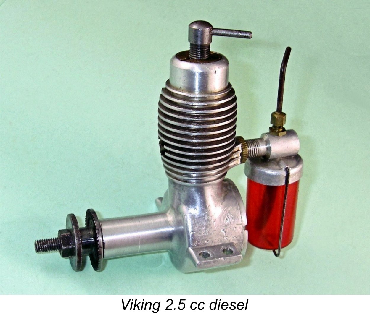
The initial retail price was 27 kr., which was clearly an artificially low figure intended to stimulate initial interest and get a few examples out into the field. It was soon increased to a more economically-rational 54 kr. By the time of publication of the 1968 catalog from DMI, the stated cost was 87 kr. A brief earlier article about this engine appeared a few years back on Ron Chernich’s invaluable “Model Engine News” (MEN) web-site. That article may still be accessed through this link. Considering its introductory date, it’s a remarkable fact that a total of some 20,000 examples of this retrospective sideport design ended up being produced over its almost twenty-year production life. These are noteworthy statistics for a model engine design which was basically outdated at the outset from a technical perspective. The only parallels that we The reasons for the widespread long-term use of the Viking 2.5 cc diesel by Scandinavian modellers were closely parallel to the reasons for the ongoing use of the E.D. and Mills sideport engines in Britain and elsewhere. The Viking engines were well made, sufficiently robust, easy starting, dependable, reasonably priced and well marketed, so that owners could easily get spare parts from all Danish hobby shops. Even as late as 1979, some ten years after the final withdrawal of the Viking 2.5 cc model, it remained possible to find new spare parts in certain Danish model stores. The Viking 2.5 cc diesel was an exaggeratedly long-stroke unit featuring bore and stroke measurements of 12.72 mm and 19.50 mm respectively for a displacement of 2.48 cc. These figures were actually borrowed from the earlier Thorning III model (which remained in production at the time when the Viking 2.5 first appeared). The engine weighed a quite reasonable 145 gm (5.12 ounces) complete with tank. Claimed output was 0.15 BHP @ 6,000 rpm. This was very definitely a low-revving long-stroke unit whose strong suit was the development of high torque at low speeds.
However, in the case of those two models the motivation was almost certainly to facilitate the effective use of dual bypass/transfer ports, one on each side. The use of sideport rear induction pretty much mandated the use of a single front exhaust if twin opposed transfers having reasonable timing were to be employed. The detail and workmanship displayed in the Viking 2.5 were first class. The way in which the lower fins were flared into the inlet boss at the rear is particularly noteworthy. Cutting those fins in this configuration required that they be formed with a slitting saw (or possibly a gang of them) while the crankcase was rotated around the bore axis between very precise limits. Quite a challenging manufacturing step, and one which most manufacturers would probably have sidestepped for cost reasons. That said, it does result in a very attractive appearance. The fuel tank of coloured plastic (blue initially, later red) is also very eye-catching. Further attention to detail may be seen in the design of the needle valve assembly. All versions of the engine used an externally-threaded steel needle. Prior to the summer of 1953 the engines featured a neat but fragile screw-in cast carburettor body which incorporated both the tank top and an internally-threaded It appears that experience in the field soon demonstrated that the cast carburettor was unacceptably prone to breakage from one cause or another. It was evidently for this reason that the cast carburettor was supplanted in the summer of 1953 by the far more sturdy and sophisticated set-up seen in the attached photographic images. The induction venturi tube was now turned from aluminium barstock while the tank top was now a separate soft aluminium stamping. The "spraybar" was now a two-piece screw-in set-up featuring a surface jet on one side and a needle carrier on the other. The screw-in surface jet did double duty by securing the stamped tank top in position. The little locking thimble on top of the needle carrier made for an excellent air-proof joint as well as ensuring the stability of the needle setting. This "gland nut" feature was similar to the designs seen on contemporary high-performance engines like the Dooling, ETA, Nordec, Super Tigre and older McCoy models. The rather thin drop-in Meehanite cylinder liner was retained in the upper cylinder jacket by an externally threaded brass plug that engaged with an internally threaded recess at the top of the cylinder casting. The G/A cut-away section reproduced above should make this clear. The hardened nickel-chrome steel piston had an exaggeratedly-long skirt, which was thought necessary in the early days to ensure adequate compression seal. A number of other early designs such as the original FROG models from England also exhibited this feature.
Another legitimate criticism is the somewhat insubstantial construction of the cylinder liner. As noted earlier, this is made with very thin walls. Moreover, it is split at the sides at exhaust port level to create the two lengthy bypass passages. This makes the lower cylinder extremely prone to "pinching" when it is installed in the crankcase. The fact that the bore has almost no taper doesn't help - many of these engines are encountered with pinched pistons around bottom dead centre. Luis tells me that this is a well-recognized trait of these engines, and one which gives rise to the need for great care in re-assembly. It's essential that any high spots be relieved so that the liner is no more than a smooth light push fit all the way down. It's also vital that scrupulous cleanliness be maintained during re-assembly. The above issue is somewhat exacerbated by the fact that the cylinder liner is subject to hold-down stresses throughout its full length. In consequence, the two halves of the lower cylinder are somewhat prone to distortion though microscopic buckling. The Thorning III with its identical cylinder design got around this by incorporating a location flange just above exhaust port level which bore upon the top of the crankcase casting. The cylinder was retained by a "dog collar" which acted against this hold-down flange, thus relieving the actual cylinder liner of any hold-down stresses whatsoever. It has to be said that in mechanical terms the Thorning design was greatly superior, if far less elegant in terms of appearance. The centre of the very substantial compression screw is drilled out. The weight saving resulting from this additional manufacturing step is negligible, making it appear likely that the motivation was actually to eliminate any chance of point contact between the screw and the top of the contra piston. This configuration has been shown to significantly reduce the tendency of compression screws to unwind under operating conditions. It’s a modification that I have frequently and successfully applied to my own “flying” engines.
We already noted the summer 1953 switch from a cast carburettor body to a composite affair utilizing a stamped tank top. The first engines had blue plastic tanks, but from 1954 onwards the tanks were made of red plastic. Apart from these few relatively minor changes, the engine remained unaltered right through to the end of production. At the outset, a production rate of 25 units per week was achieved. However, this must have been increased significantly fairly early on, since by September 1952 it was claimed that a total of some 7,000 examples of the Viking 2.5 cc diesel and its low-production 3.2 cc companion (see below) had been sold. As of January 1st, 1956, production figures for all Viking models was said to be around 12,000 units. By 1959 this total (again for all models) had reached a claimed 15,000 units. Throughout the life of the marque, the 2.5 cc model remained the most enduringly popular member of the Viking family. In all, some 20,000 examples were manufactured prior to the withdrawal of the range in 1969. This represents around 80% of the total number of engines produced for all models. The Viking 2.5 cc Diesel on Test
The writer of the Viking test report praised the engine's handling and overall performance very highly, citing it as the most powerful Danish 2.5 cc engine yet to appear. He found a peak output of 0.132 BHP @ 6,000 RPM, a little less than the manufacturer's claim of 0.15 BHP at the same speed. Having two well-used but still highly servicable and completely original examples of the engine on hand, I felt that I had no excuse for not putting the test stand back to work and conducting an independent evaluation of the manufacturer’s performance claim. I was also curious regarding how my results would compare with those published in "Teknik for Alle". Frankly, I was a bit skeptical going into this test, because that’s a lot of power at such a relatively low speed! If the manufacturer’s claim was anywhere near accurate, the engine was a mega torque producer at low revs. In theory, it should turn an 11x6 APC airscrew at somewhere near its claimed peaking speed of 6,000 RPM. I elected to begin with that prop just to see if theory was borne out in practise. My skepticism was reinforced by Luis's comment that he and his friends used to use SEMO 8x6 plastic airscrews on their Viking 2.5 cc models. Admittedly that prop was a bit of Neither of my examples of the Viking are anything like pristine - they have both clearly seen a lot of use and have led a hard life - note the broken cooling fins! However, they remain in good mechanical condition. The compression in both examples is a bit on the leaky side, but all other fits remain excellent and there's plenty of compression for starting and running. The two engines are both in completely original condition, hence being truly representative test samples. The tanks on both engines are faithful replicas very kindly provided by Luis (thanks, mate!), but that doesn't affect the engines at all in an operational I've had these engines for many years and had run them both a long time ago, but that was way back then .........I welcomed the present opportunity to get reacquainted! I elected to give both engines a chance to show what they could do, because there's always value in duplicating tests with different examples of the same engine. A wise decision, as things turned out........... So without further ado, the first engine to be tested went into the test stand with an APC 11x6 prop installed at the business end. A point to note here is the fact that the undersides of the mounting lugs on these engines are not laterally parallel - they slope upwards towards the outer edges. Accordingly, they don't sit flush on a pair of parallel flat mounting surfaces such as those of a typical test stand. I use shims under the outer edges to spread the load and thus prevent distortion or even cracking of the crankcase. I recommend that others do the same. I used a straight fuel mix of equal parts ether, kerosene and castor oil, which generally works pretty well in these old long-stroke sideport engines. It was a bit of a chore to get the Viking going first time thanks to the years of storage oil that remained in it. However, once I got it well flushed out with fresh diesel fuel it started readily enough.
Once running, the engine was a real pleasure to set thanks to the very fine mixture control afforded by the externally-threaded needle. Compression settings too were non-critical and easily established. The engine ran very smoothly and consistently at all times with no detectable tendency to sag as it warmed up. The one oddity was the way it looked when running - throwing the exhaust gas stream forward right into the prop disc where it was comprehensively dispersed, oil residues and all! No matter where you stood, you got well doused with castor oil spray! Shades of WW1....... The following speeds were recorded on the various props tried:
By the time I got to the APC 10x6, vibration levels were becoming pretty noticeable. Because of the vibration issue, I never got close to the 8x6 prop size which Luis Petersen recalled using in former days. In any case, such a prop would have taken the engine way past its peaking speed. This is not an engine to under-prop! The tester for "Teknik for Alle" had said as much way back in 1950, and he was right. The above results generally met my expectations going in. It's worth noting that my pre-test prediction of something close to 6,000 rpm for the APC 11x6 proved to be pretty accurate! The engine peaked as expected at a slightly higher speed than claimed by the manufacturer, but didn't deliver quite the quoted power. I found a peak output for this example of around 0.124 BHP @ 6,500 rpm. Since these figures are generally consistent with the findings of the previously-cited test report in "Teknik for Alle", I was feeling pretty This is actually a pretty respectable performance for a 2.5 cc sideport diesel of basically vintage design. There's no doubt that this engine would do a highly creditable job of flying a sport or scale model - those big props shift a lot of air! A 10x8 would probably be an excellent flying prop for this engine. Moreover, the Viking's user-friendly handling characteristics would greatly add to the enjoyment of using it in the field. No wonder it remained as popular as it did for so long! OK, so much for engine no. 1. Next up was its partner, engine number 2! Ths one proved to be if anything a little "leakier" in the compression department than its companion, and I actually found that my standard remedy for worn engines - an extra prime of straight upper cylinder lubricant - was a great help in starting. Using this approach, it started just as readily as its opposite number. Once going, running qualities too were just as positive. It only took a couple of test runs on different props to confirm that this example was going to surpass the performance of engine no. 1 by a substantial margin. It was well up on all props tested above 6,000 RPM. The results below speak for themselves:
Now that's a bit more like it! The implied peak of around 0.142 BHP @ 6,700 RPM is as close to the manufacturer's claim as you could wish, exceeding the figures reported in "Teknik for Alle" by a healthy margin! Note however that as expected, the peak was found at a slightly higher speed than that cited either by the manufacturer or the "Teknik for Alle" writer. For a 1950 2.5 cc sideport diesel, this really is a pretty impressive performance. Massive amounts of lovely low-end torque on hand, allowing the engine to swing a really meaningful prop to good effect. Combine that with their excellent handling, and these engines undoubtedly deserved their positive reception from the Danish modelling public! Viking 3.2 diesel – 1950-1951?
The external appearance of the engine was little changed. The most obvious difference is the larger-diameter unfinned top portion of the cylinder jacket which had to be sized to accomodate the larger-diameter brass disc required to retain the bigger-bore cylinder. The cooling fins are less inwardly tapered at the top to accomodate this feature. The grooves between the fins are also less deeply cut to provide sufficient material for the enlarged installation bore for the cylinder liner. Apart from these relatively subtle differences, it would be very easy to mistake this engine for the more common 2.5 cc model. The illustrated example of this relatively rare engine is a well-used unit which was very kindly made available to me by Luis Petersen. Before sending it to me, Luis took it apart to check the internal geometry. The measured bore and stroke of this example are 14.30 mm and 19.65 mm respectively for a displacement of 3.16 cc. Near enough, allowing for "lathe operator's license"!
One interesting observation is the fact that the manufacturers don't appear to have taken the extra bore fully into account when laying out this design. It would appear that they just assumed that the 2.5 cc crankcase using the same stroke would accommodate the extra bore, hence making no design changes. As a result of this incorrect assumption, the piston in this example had been contacting the backplate. This required correction through some appropriate shimming of the backplate. This is the kind of error that we might expect from a designer who drew his engineering drawings in chalk on a work-bench! This slightly enlarged version of the standard 2.5 cc model seems to have been intended primarily for car and boat operation, since most of the relatively few examples encountered today are equipped with a heavy flywheel. That said, the checked weight of 157 gm for the illustrated aero example is only 12 gm more than the weight of the 2.5 cc aero model.
The retail price of this engine was set at 54 kr. However, it does not seem to have attracted much customer interest, since only around 300 examples were reportedly produced. Manufacture seems to have ended in 1951 after only a year or so. Consequently it is a very rare engine today. Claimed output of this model was 0.20 BHP @ 8,000 rpm. If true, the engine delivered a power-to-weight ratio that was well in excess of that developed by the 2.5 cc version. It also peaked at a considerably higher speed. I was hoping to test this claim prior to the initial publication of this article, but as events transpired the engine only arrived a few days before the publication deadline. Nonetheless, I set it up in the test stand right away to attempt to conduct a quick test using a range of suitable props. At that point I was hit with the first of a series of time-consuming problems. Firstly, the pin which secured the prop driver to the shaft sheared off during my initial starting attempts. I replaced it - same problem with the replacement! So I ended up making a split collar mounting for the prop driver, which should have been used from the outset, as it was on the later 2.5 cc models. End of that particular problem...... The next issue was the fact that the contra piston proved to be far too loosely fitted. It was actually following the power piston up and down during starting attempts. So I had to make a new replica replacement, which I lapped to a perfect fit. Another problem solved, but it took time .............
Once going, the engine ran extremely smoothly, never missing a beat. My replacement contra piston turned out to be perfectly fitted, holding its settings firmly while remaining fully adjustable at all times. Needle valve response was also very positive. Given the time pressures under which I was working, I decided to spot-check a few of the same props used in the earier 2.5 cc tests. It was immediately clear that this engine developed considerably more torque than its smaller brother. I got as far as measuring 5,500 rpm on the Zinger 11x7 wood (0.124 BHP), 6,800 rpm on the Top Flite 10x7 Power Point wood (0.156 BHP) and 7,200 rpm on the APC 10x7 (0.167 BHP). However, at this point the glued-on needle carrier fell off! Evidently the glue used wasn't up to the task - it was more of a cosmetic repair. I later repaired the component with JB Weld and then undertook a re-test of the engine. This time I made it through the selected suite of test props, with the results shown below:
These results confirm that the 3.2 cc model definitely possesses a significant performance advantage over the 2.5 cc version. What's more, it does peak at a somewhat higher speed, just as claimed by the manufacturer. However, the implied peak output of 0.168 BHP @ 7,400 RPM falls well short of the 0.200 BHP @ 8,000 RPM claimed by the manufacturer. Even so, the 3.2 cc diesel should have appeared rather attractive to some owners of the 2.5 cc model, since it was a simple bolt-on replacement for the smaller unit. This created the possibility of gaining extra "urge" at a minimal weight penalty. Rather like the relationship between the original FROG 100 diesel and its larger bolt-on replacement, the FROG 180 diesel, of which more elsewhere. Viking 3.2 Glow-Plug Model – 1952-1954
As with the earlier diesel models, twin bypass/transfer ducts were provided, one on each side. In effect, this was the familiar Cox-style four-port reverse-flow scavenging system. A quality touch was the design of the needle valve assembly, which followed the estabished "racing engine" surface jet pattern by using separate screw-in needle carrier and fuel jet components with an externally-threaded needle. Tension was provided by a split in the needle carrier which in turn was tensioned by a knurled gland thimble. Both elegant and effective!
Unfortunately, this model incorporated a few design issues which prevented it from becoming a success. To begin with, it featured a very heavy almost solid cast iron piston which was not conducive to low vibration levels, even with the designer's use of a counterbalanced crankweb. In this, it followed the pattern established previously with the sideport diesel models described earlier. It would appear that Tommerup Clausen had not yet come to appreciate the importance of minimizing an engine's reciprocating weight. In addition, clearance “steps” were milled in the piston crown to serve as deflectors for incoming mixture entering the cylinder via the two transfer ports. The “steps” created in this way destroyed the combustion chamber shape by creating peripheral pockets on opposite sides which limited both compression ratio and combustion efficiency. A volumetric check of the compression ratio of my example gave a figure of only just over 6 to 1, which is very marginal indeed for a glow-plug motor. The crankshaft ran in two bronze bushings inserted from front and rear, but was made a little too flimsy for adequate strength and stability, especially given the very heavy piston with its attendant high reciprocating loadings. Consequently, failures were by no means unheard of. In addition, the lower cylinder liner was made too thin for adequate structural stability, particularly in view of the two long In the case of the 3.2 cc glow-plug model, this issue was alleviated to some degree by the fact that the cylinder was vertically located by a thick annular expansion at the top which bore upon the top of the installation bore in the upper crankcase. This relieved the lower cylinder of any installation stresses. A final issue was the design of the disc rear rotary valve. The disc itself was very nicely machined from some form of laminated plastic material along the lines of Tufnol. This was a very good choice of material given the fact that Tufnol discs operating against aluminium alloy backplates had been shown to wear very well. The problem was that Clausen had clearly failed to appreciate the fact that there was no need to arrange for mechanical pressure to be exerted between the backplate and However, Clausen mounted the disc in this engine on a separate steel spindle which passed through the backplate and was equipped with a fairly strong coil spring retained by a split pin at the rear. This created a considerable amount of continuous mechanical pressure between the static and rotating working faces of the valve. The rear end of this spindle (minus spring and split pin) is clearly visible in the above component view. While the resulting seal was very good indeed even with the engine stopped, the friction drag which this arrangement created was very high. One can feel the drag simply by turning the engine over by hand - it must have cost a considerable amount of power. As a result of all these issues, the engine did not succeed in penetrating the marketplace. It appears that only some 100 examples were manufactured in total, making this an extremely rare and highly sought-after engine today. I'm very much in Luis Petersen's debt for enabling me to acquire my own example. The Viking 3.2 cc Glow-Plug Model on Test
I wasn't expecting this engine to be a powerhouse given the maker's own claims. The combination of the very heavy piston with a rather lightly-built crankshaft led me to decide that I would not push the engine much past the advertised 12,000 rpm. As it turned out, this was an entirely appropriate decision. In keeping with the above considerations, I began with an APC 8x7 airscrew fitted. When turning the engine over slowly by hand, the drag arising from the over-tensioned disc valve was very apparent. However, there it was, and there was nothing that I could do about it. Following an exhaust prime and a few choked “bump” turns to fill the fuel line and check the plug, the engine immediately displayed one of its more endearing characteristics by starting up right away. It was to continue this exemplary starting behavior throughout the test, never requiring more than two or three flicks to start. Once running, the engine quickly settled down, turning the 8x7 prop at a commendably steady 8,900 rpm. Not much power in evidence, but it was shifting a fair bit of air. Running was extremely smooth, with no trace of a misfire and no tendency to sag. The one fly in the ointment was a very noticeable degree of vibration – the poor old test stand was getting quite a shaking! Speeds continued to climb as the loads became lighter. Response to the needle valve was very positive, making the establishment of the optimum setting a very simple matter. Starting and running qualities continued to be beyond reproach, but the vibration issue understandably worsened as speeds rose. Nonetheless, I persisted, finally obtaining the following results:
The two WB props are wide-blade airscrews specially created by cutting down larger APC items to fill some glaring gaps in my set of calibrated test props. As can be seen from the above data, the engine had obviously begun to run out of puff by around 12,000 rpm. The two smallest props tested clearly demonstrated that it simply didn’t want to run much above that point. The figures reported above imply a peak output of around 0.206 BHP @ 11,700 rpm - a little less on both counts than the manufacturer’s claim, although not greatly so. The Viking glow-plug model was certainly considerably more powerful than its 3.2 cc diesel companion in the range.
This was an extremely frustrating exercise, because my long experience with model engines leads me to believe very sincerely that this engine has a far greater potential than it showed on this test. The induction, transfer and exhaust arrangements all speak to a relatively strong performance potential. If I had been planning to actually use one of these units, the first thing that I would have done is to set the piston up in a milling machine and mill away much of the piston interior to lighten it, leaving the bosses intact. I sincerely believe that this would have considerably improved the engine’s ability to run faster while at the same time greatly reducing operating stresses upon the conrod and crankshaft. I would also have modified the disc valve mounting to eliminate the very considerable drag imposed on the engine by the overly-powerful and quite unnecessary spindle tensioning spring. The best approach would probably be simply to fit a machined tubular spacer of the correct length in place of the spring. Alternatively, one could fit a shorter or far lighter spring. This would still leave the matter of the inefficient combustion chamber unresolved. However, given the presence of those two piston cutaways there’s really not much that can be done about this unless one were to make a new head from scratch. If these modifications were carried out, I could readily envision the engine equalling or even exceeding the manufacturer’s performance claim and doing so at a greatly enhanced level of reliability. It’s a great pity that Tommerup Clausen failed to appreciate these problems and their very obvious solutions. He had a potentially excellent design here, but one which was quite unable to show its true potential as released. Viking 0.75 Red Helm (Red Head) diesel – January 1955 – 1963?
The Red Helm weighed in at 42 gm. The manufacturer made no specific power output claim for this model, instead contenting himself with stating that peak power was delivered at 14,000 rpm. The engine sold at a retail price of 54 kr. Unfortunately, this model too suffered from a serious design defect. Wishing to avoid the use of the McCoy’s O-ring contra-piston, Clausen elected instead to use a steel contra piston which was stamped from steel plate. This component frequently leaked quite badly, as a result of which the Red Helm quickly acquired a rather poor reputation among modellers due to the starting difficulties which often resulted from this leakage. Small diesels are hard enough to start on high-speed props without a handicap of this sort! Clausen evidently came to recognize this problem, since some of the later examples had conventional turned and lapped contra pistons. But by then the damage to the engine’s reputation had been done. Thanks to this issue, the Red Helm never became a strong seller. Production typically averaged only some 25 units in three weeks, and at times it was much less. During the engine’s relatively long production life extending from January 1955 to around 1963, only about 2,000 examples were reportedly made in total, presumably in small intermittent batches as dictated by demand. No performance information is available. Viking 2.48 Super diesel – 1956-1963?
Bore and stroke of this model were 14.55 mm and 15.0 mm respectively for an actual displacement of 2.49 cc. The engine weighed a commendably light 118 gm (4.16 ounces), although this low weight was achieved at the expense of a certain fragility. Claimed output was 0.24 BHP @ 14,000 rpm. The engine sold for a retail price of 69 kr. Unfortunately, this model perpetuated some of the design flaws of other Viking models, notably the Red Helm. The contra piston followed the same pattern by being formed as a steel stamping. This component was prone to leakage, just as it had been with the smaller model. Later examples had turned and lapped contra pistons to deal with this issue. However, the engine’s overall construction was too light for adequate distortion resistance and durability. The original crankshafts manufactured by Clausen proved to be somewhat undependable, but durability was later improved through the use of forged shafts which were produced elsewhere by a sub-contractor. Production of this model typically averaged around 25 units in two weeks. A total of about 3000 units were reportedly manufactured in total. Conclusion As the above review will have shown, the Viking range was bedevilled throughout its life by a succession of design flaws which appeared on various models. The one model which appears to have been relatively free from major design issues was Tommerup Clausen’s first design, the 2.5 cc sideport diesel. That said, even that model had its Achilles' Heels in the form of its excessively heavy piston and distortion-prone cylinder liner.
If Clausen had been able to shake off a few design tendencies such as the application of excessively light and over-simplified construction plus the use of excessively heavy pistons, the range might well have fared better in the long run. However, that was not to be. Regardless, the Viking venture has left us with a number of highly servicable engines which careful owners can still enjoy today. In closing, Luis and I would like to extend our thanks to everyone who assisted in the preparation of this article. Luis wishes to extend special thanks to “Mr. DMI” Svend Schou, whose scrapbook has been an invaluable source of information. However, we don’t claim to know it all! If any reader can offer corrections or additions to the text, please get in touch! ______________________________ Article © Adrian C. Duncan & Luis Petersen First published May 2016 Updated October 2018 |
||
 This is the third article to appear on this web-site on the subject of Scandinavian model engines. Earlier articles have covered the
  My initial intention was merely to edit Luis’s article into colloquial English and present it verbatim with his permission. However, Luis himself comprehensively derailed this plan by succumbing to a fit of enthusiasm which led him to send me a significant amount of additional information on early Danish engines other than the Viking models! He also provided a great deal of photographic and documentary material which had not appeared with his original 1990 effort.
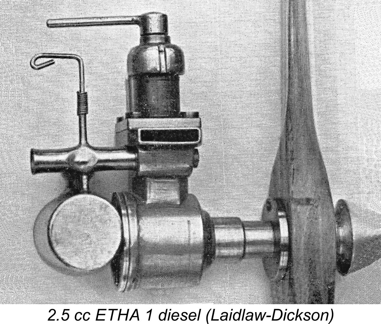 The concept of the model compression ignition engine goes back way further than many of today’s model engine enthusiasts may realize. In the past it has often been stated that the Swiss Dyno 2 cc model of 1941 was the “first” model diesel. While that view may have some validity in terms of widespread acceptance and design influence, the concept actually dates back to December 17
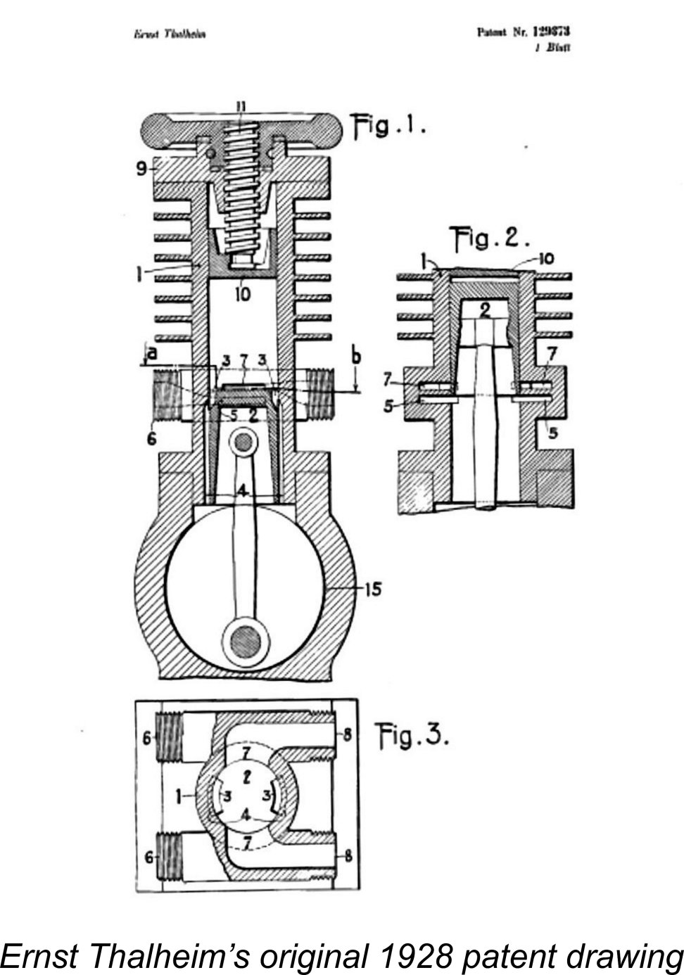 During the interim, the idea of utilizing compression ignition specifically for model engines had surfaced independently in Germany. In 1937 the talented model engineer Gustav Eisfeld of Gera, Germany began his own experiments with model compression ignition engines. However, Eisfeld chose a different and far more challenging development path by working on “true” diesels equipped with fixed compression, miniature injectors and high-pressure fuel pumps. This approach may have been directed at getting around Thalheim's patent, which specified the use of conventional carburetion along with variable compression, as the accompanying drawing from the original patent specification should make clear.
 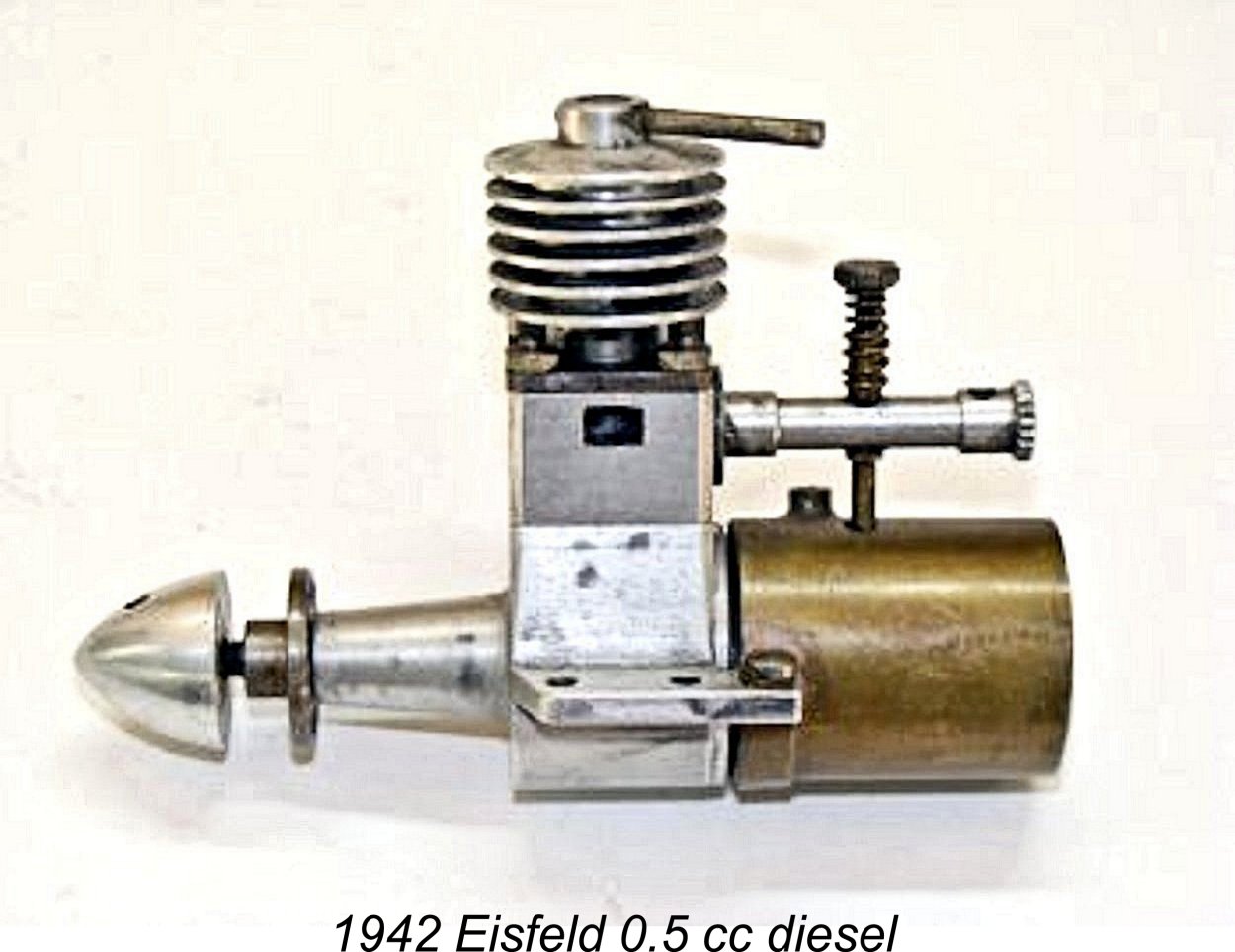 However, the manufacture of the tiny fuel pump and injector required a level of precision which could only be achieved on a series production basis through the application of the most exacting industrial methods and equipment. Such facilities were not available to Eisfeld due to the ongoing war. Since Ernst Thalheim's 1928 patent was set to expire in December 1942 in any case, Eisfeld concentrated thereafter on the development and production of his excellent conventional “diesel” models which were designed in collaboration with A. Thusius. He did however take the trouble to record his earlier experiments in an article which appeared in November 1943 in the wartime German publication “Luftwacht-Modellflug” (pp. 107-109).
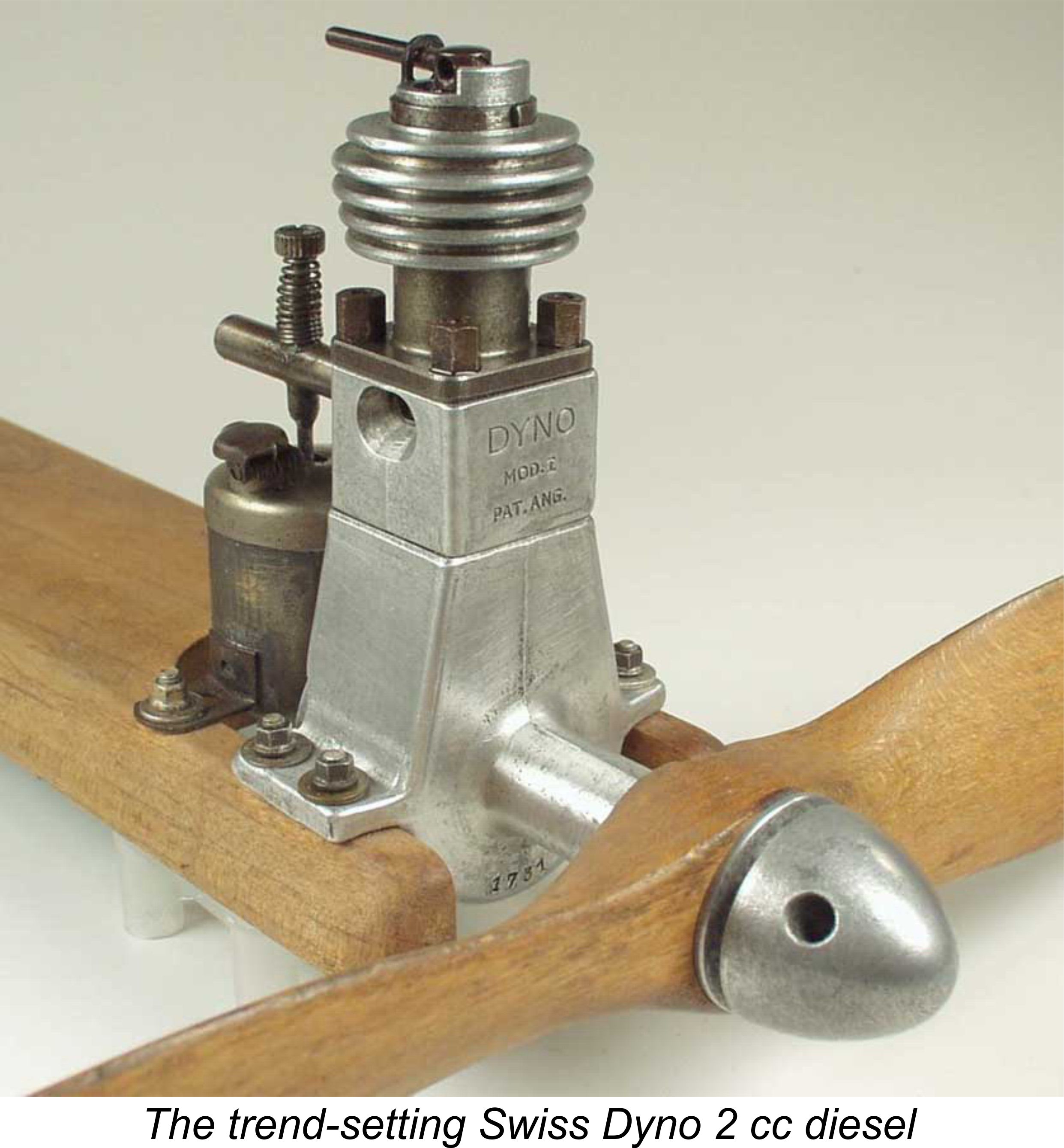 Returning now to the pre-war period, Gustav Eisfeld’s abandonment of his original 1937 diesel project left the way open for Ernst Thalheim to introduce the first commercial model diesels, which he did in 1938, ten years after the granting of his original patent. His ETHA engines were large, heavy and cumbersome. However, they were reportedly very competently constructed and ran well, thus proving the concept for all to see. They were sold through a shop located on the now-exclusive Bahnhoffstrasse in Zurich which was then owned by a certain Herr Feucht. We are greatly indebted to prominent English collector and former Swiss resident Peter Scott for the above details.
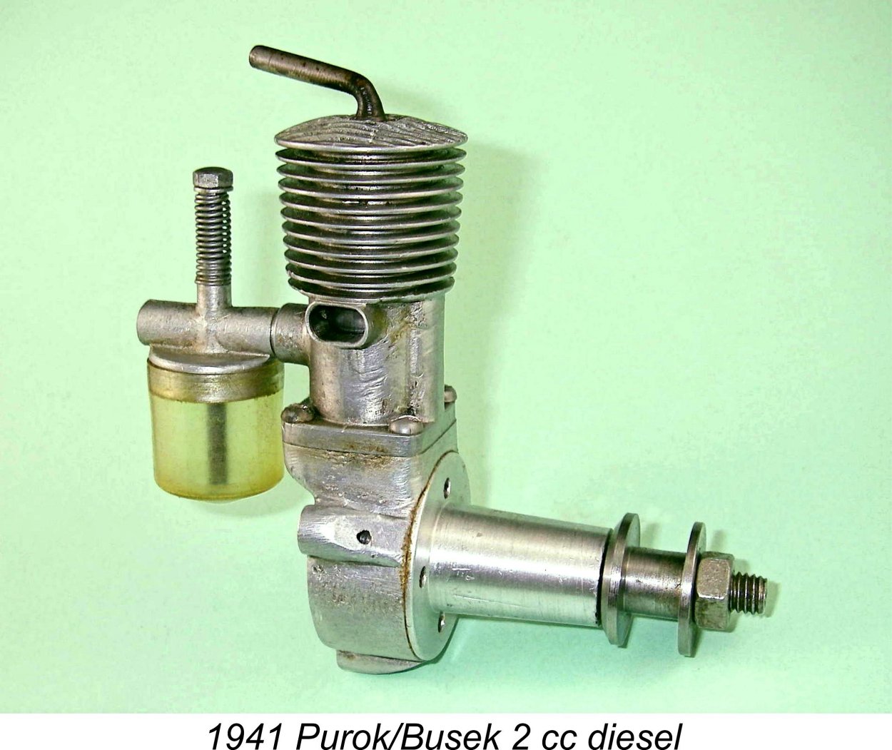 Despite the fact that by the early 1940’s most of Europe was heavily embroiled in WW2, word about this then-innovative type of model engine somehow trickled out of neutral Switzerland to reach a number of other European countries, both neutral and occupied. In an article which may still be found on the late Ron Chernich’s wonderful “
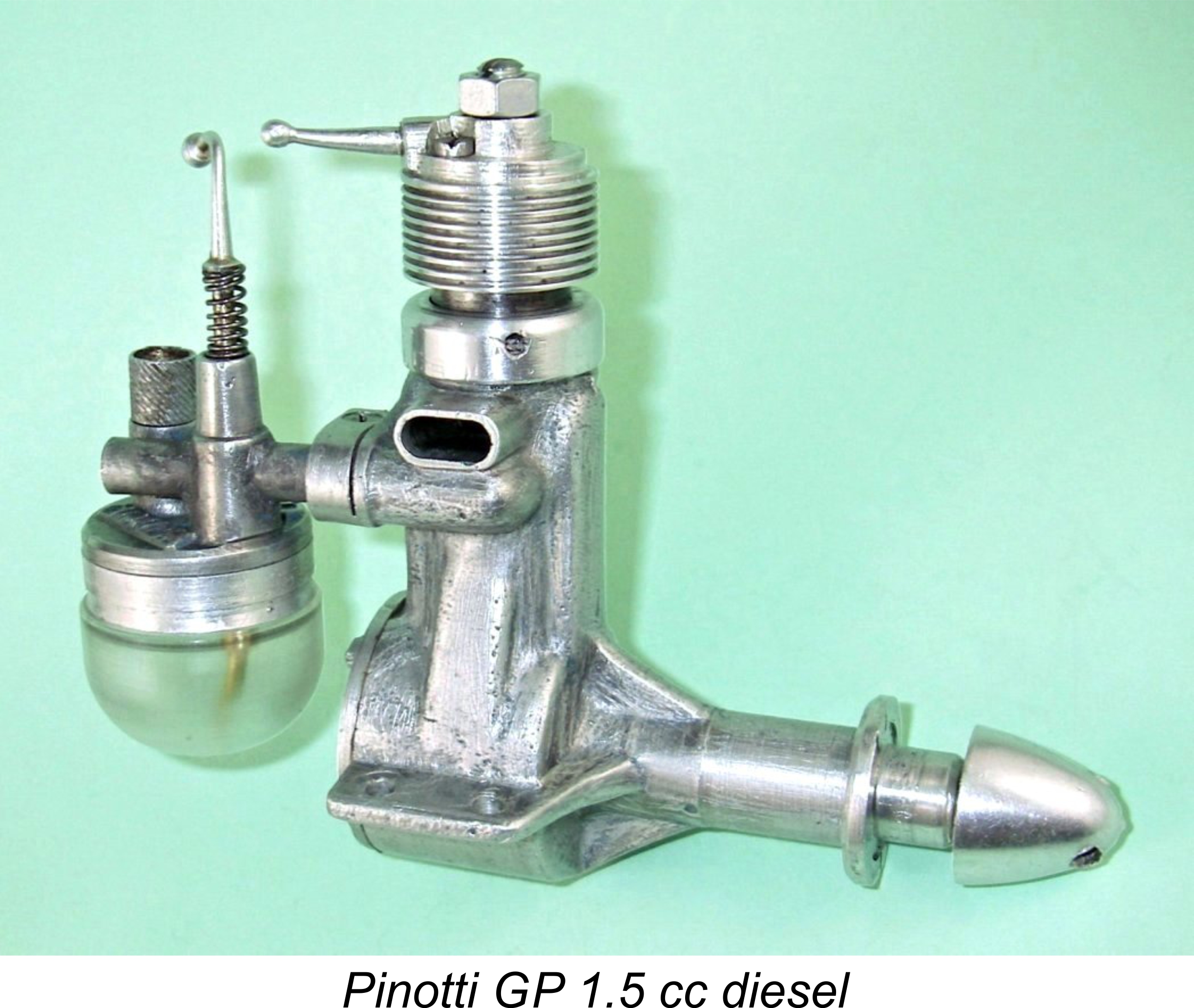
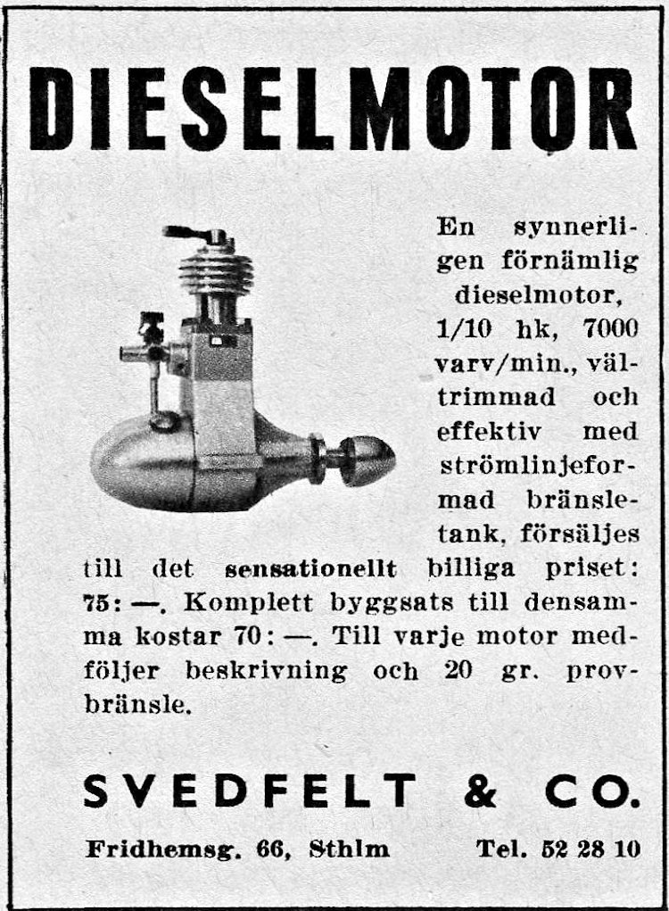 Stockholm somehow managed to arrange for the importation of a number of Dyno diesels to Sweden in 1944, as an advertisement from the September 1944 issue of “Teknik för Alla” proves beyond doubt.
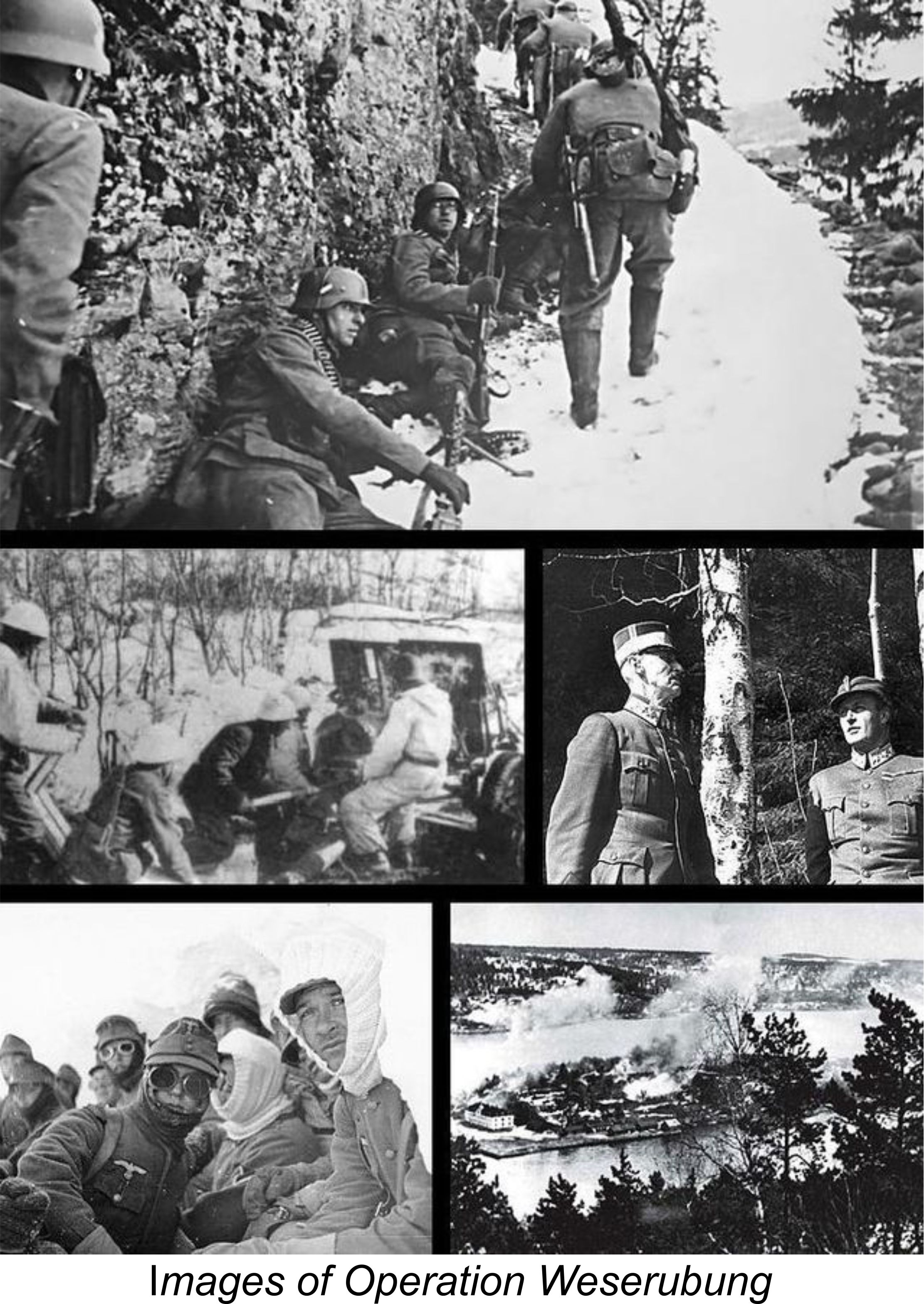 Along with neighbouring Norway, Denmark was occupied by the Germans on April 9
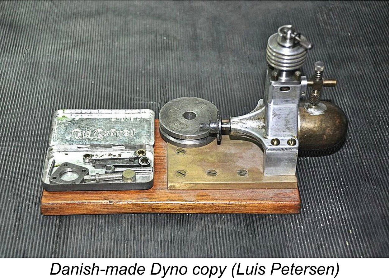
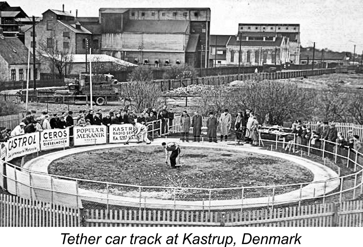 diverse choice of domestic model engines during the wartime and early post-war periods, long before Viking arrived on the scene. Until 1947, when control-line flying reached Denmark, most of these early engines were used in tether cars, boats and free flight model aircraft. The illustrated tether car track at Kastrup, near Copenhagen, was a popular facility which remained in use into the late 1950’s. The young Luis Petersen spent a lot of time there, since it was only 1 km from his home!
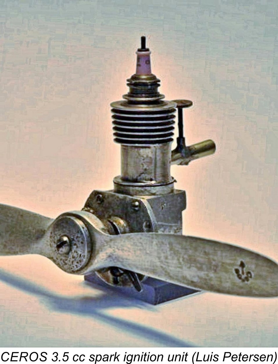 produce a number of very well-made model engines under the CEROS brand name (an anagram for his own family name and initial).
 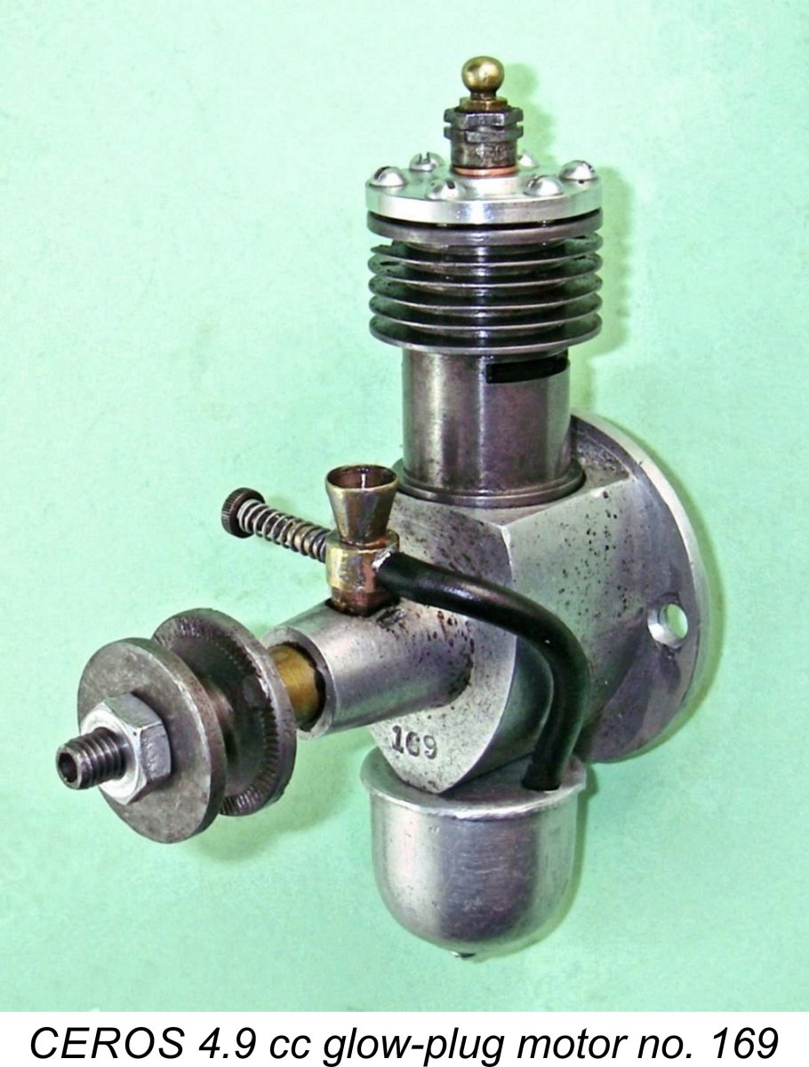 During the early post-war period, Rose returned to the manufacture of spark ignition engines, then still in widespread use in the mid and larger displacement categories. There were 3.5 cc and 4.7 cc models of this type. However, Rose was quick to recognize the sweeping impact of Ray Arden's late 1947 introduction of the commercial miniature glow-plug, and a CEROS 4.9 cc glow-plug unit duly appeared in 1949. This was heavily influenced by the design of the far smaller K&B Infant .020 cuin. model which had appeared in the USA in late 1948.
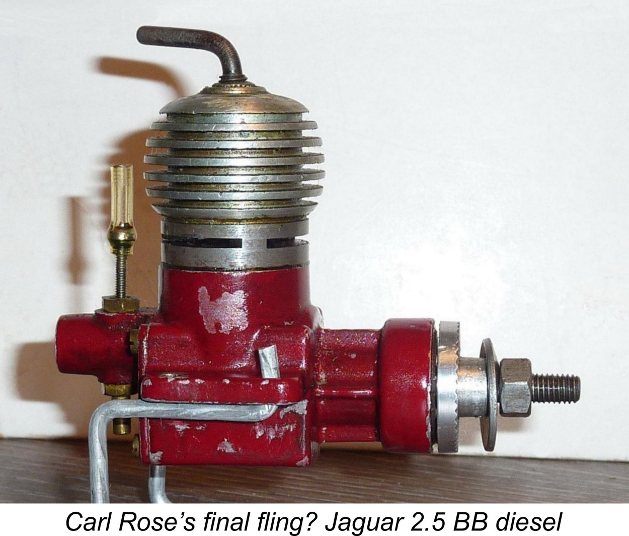
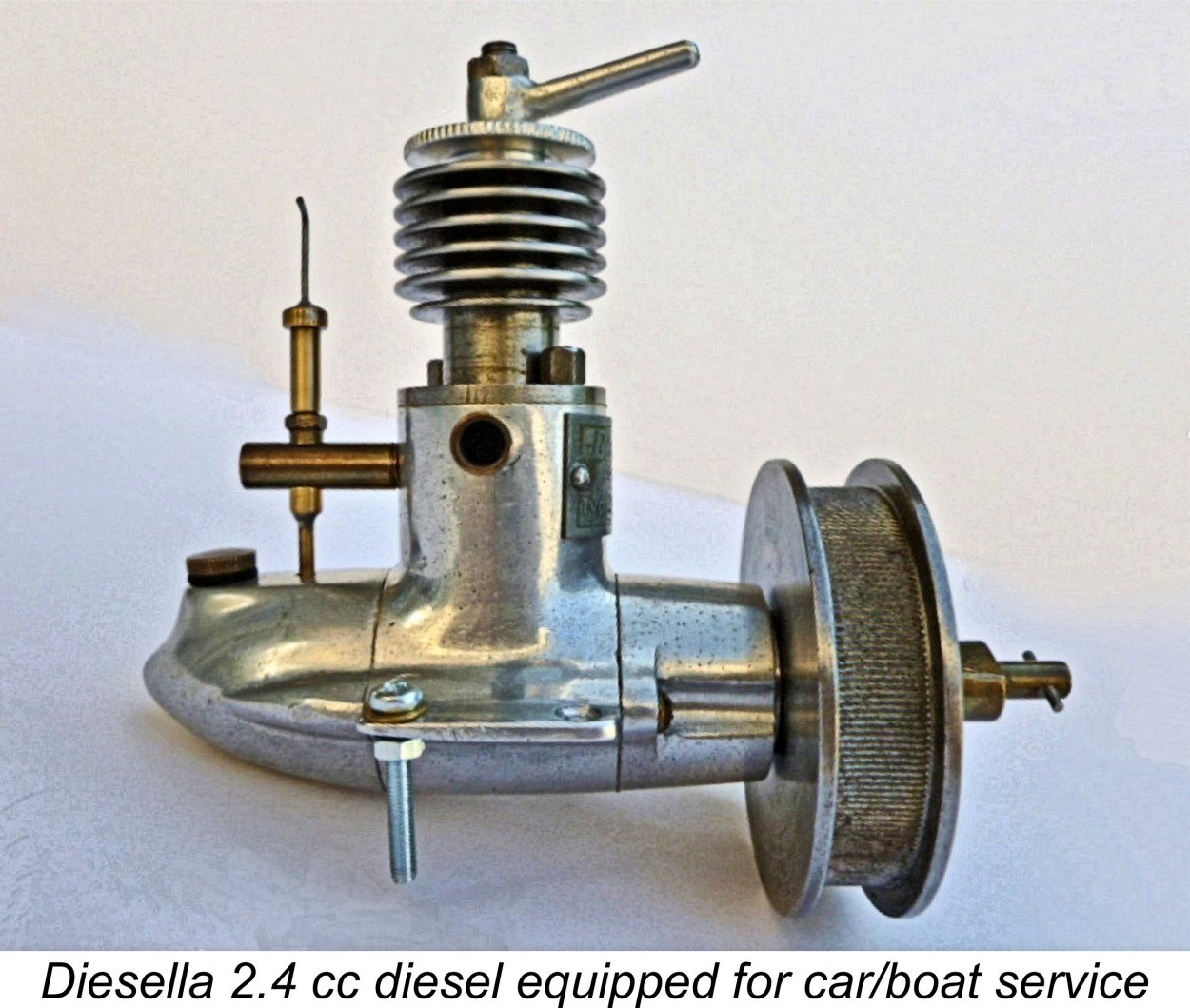 Having followed the CEROS story through to its conclusion, we return now to the wartime period. The first commercially-produced model diesel in Denmark seems to have been the Diesella 2.4 cc model. According to a Danish-language article by the then well-known Danish model flier Peter Christiansen which appeared in the January 1944 issue of the magazine “Flyv”, this pioneering model diesel was the product of a collaboration between Eli Andersen and one A. Jeppesen, two mechanically-gifted individuals who had reportedly been building their own model spark ignition engines of varying displacements since 1938. In early 1943, the impossibility of obtaining miniature spark plugs under wartime conditions led the two men to commence their experiments with model compression ignition engines. By the latter part of 1943 they had a design which they felt merited series production.
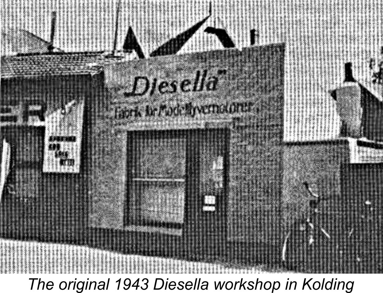 seemed barely large enough to accommodate the two men and their equipment! The primary business at this point was clearly the manufacture of model engines, since the sign on the storefront proudly proclaimed that the premises were occupied by a “Fabrik for Modelflyvermotorer” (Model Airplane Engine Factory). The chosen company name clearly reflected this business focus.
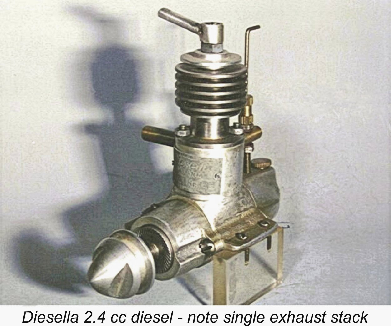 Despite its high selling price, the Diesella attracted quite a few buyers because it had no domestic competition at the outset. Luis was kind enough to share what has become my favorite story in relation to the Diesella. Apparently one of Eli Andersen’s first customers in late 1943 was an individual who was active in the growing Danish resistance movement. However, immediately after placing his order this customer was caught by the Germans during their late 1943 crackdown and was sent to a concentration camp before he could take delivery of his purchase. Happily he survived the war and returned home to Denmark .............. to find his carefully-stored Diesella model engine awaiting him as a coming-home present! A nice happy-ending story which reflects well upon all concerned!
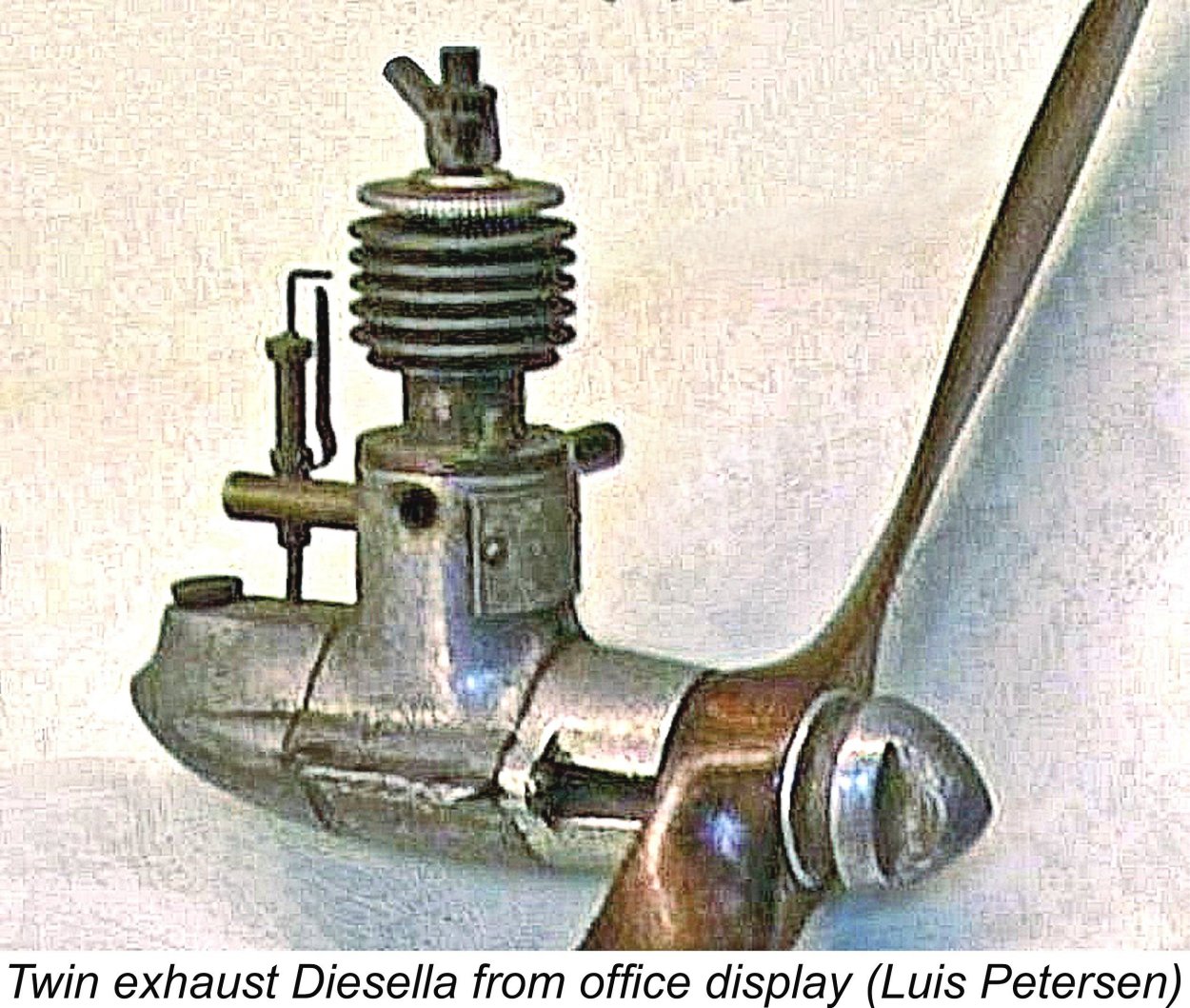
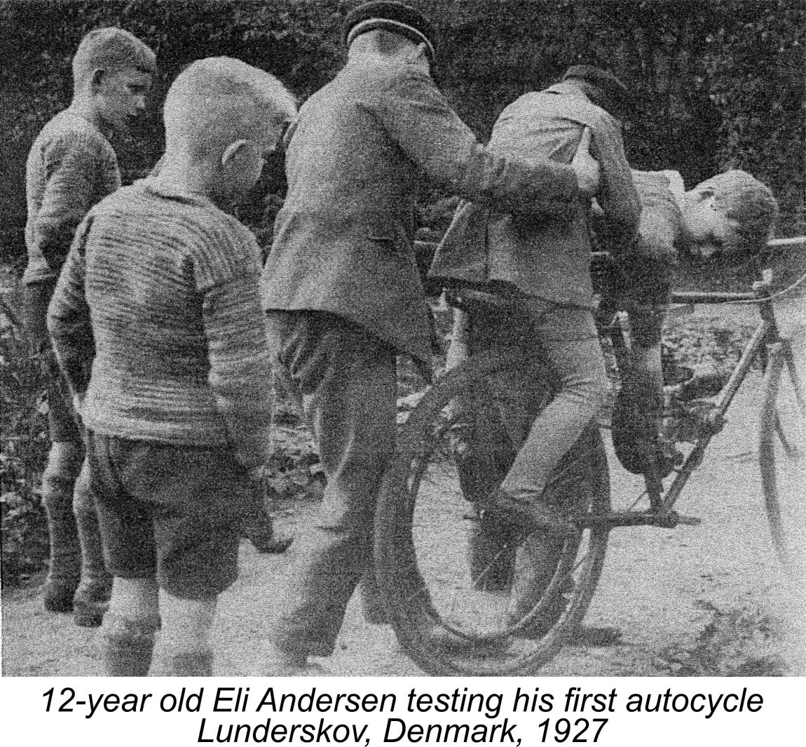
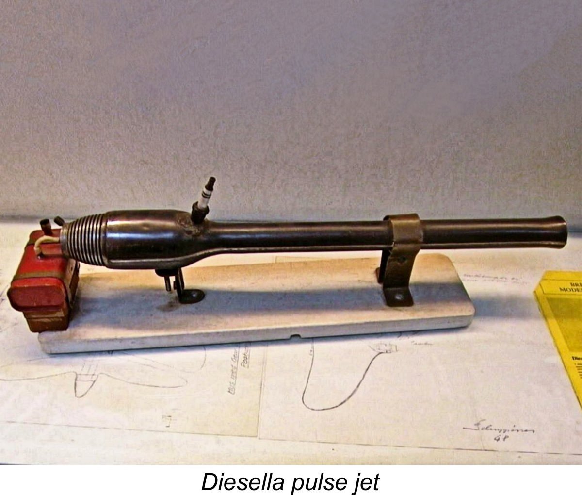
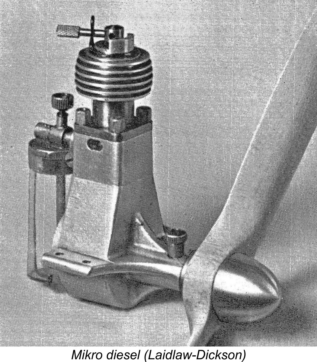 A competing Danish engine which appeared in 1944 was the 2 cc Mikro-diesel. This engine was manufactured by Kaj Neilsen of Kronprinsensgade 8, Copenhagen who had established his own business in 1938 primarily as a repair workshop for photographic equipment. His original equipment consisted of a single turret lathe!
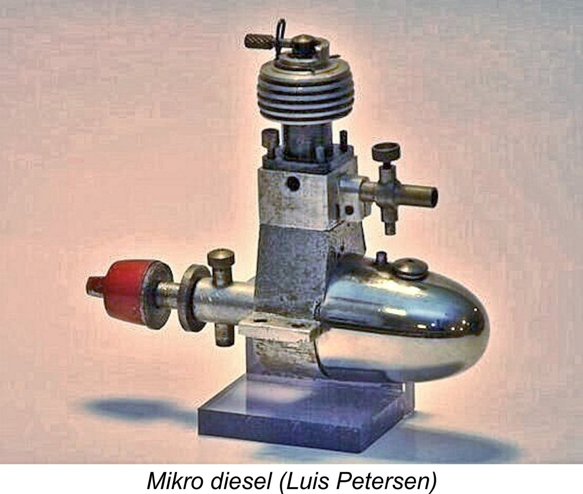
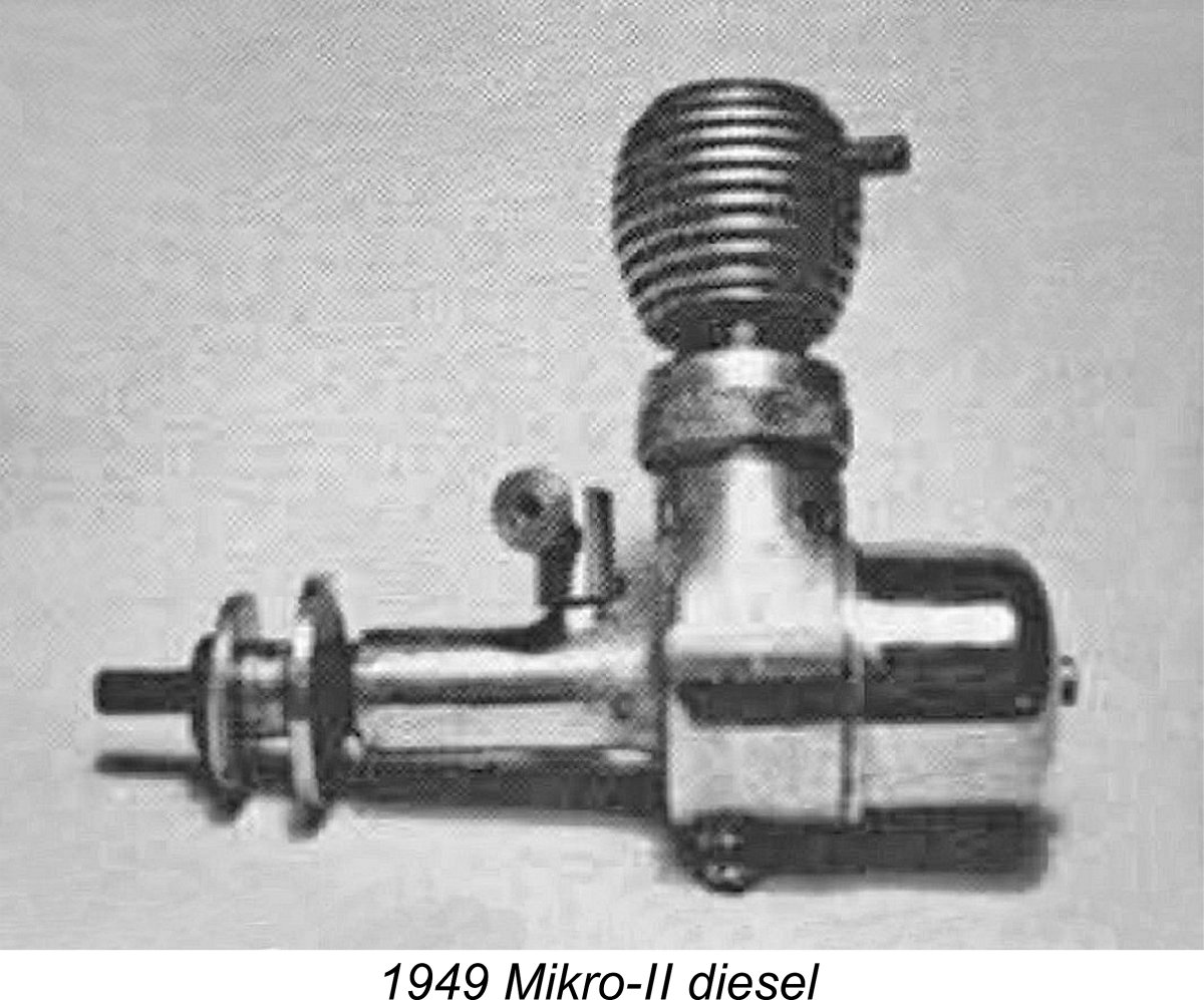
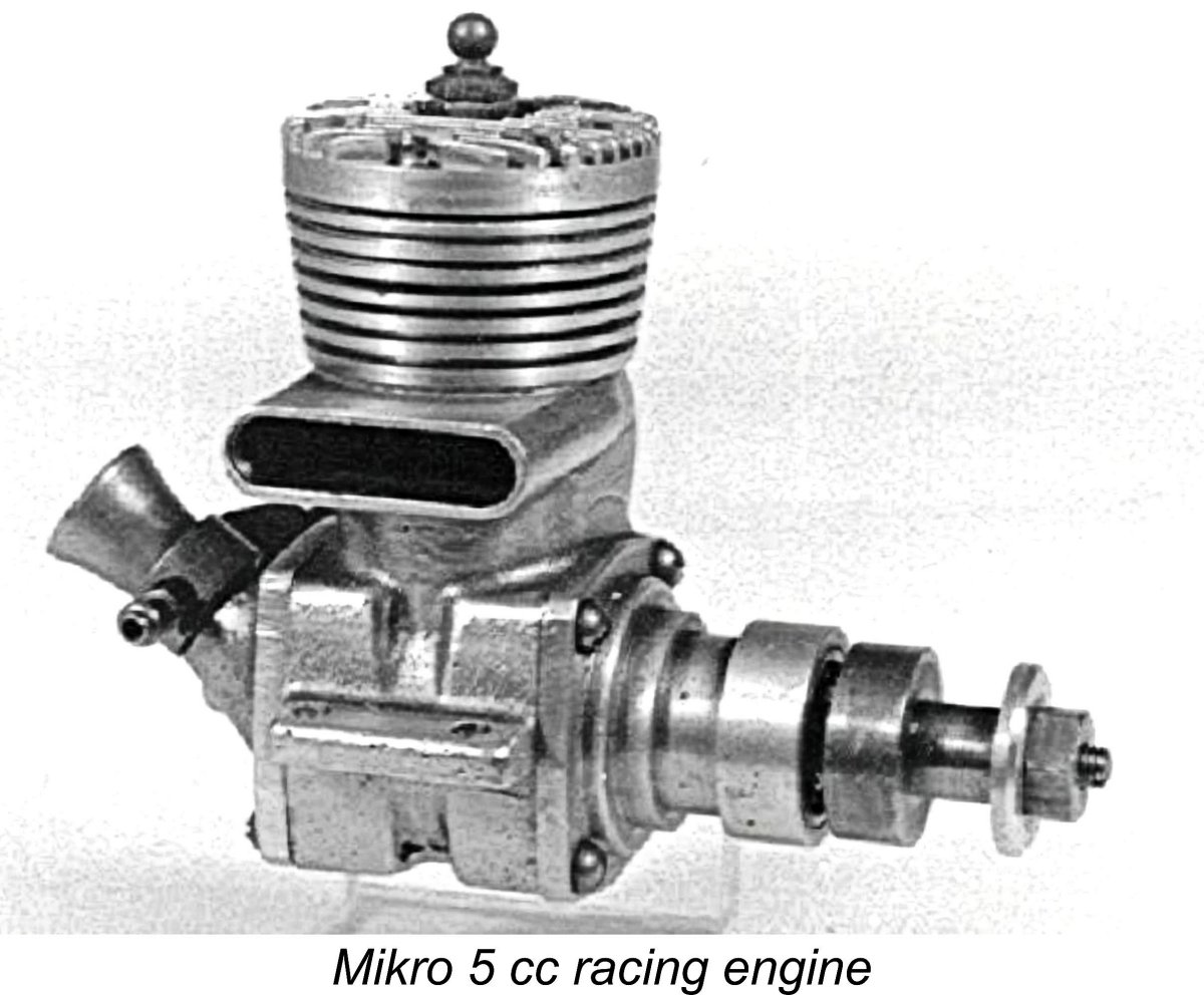
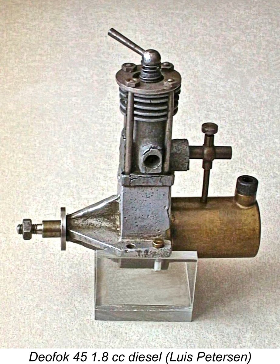
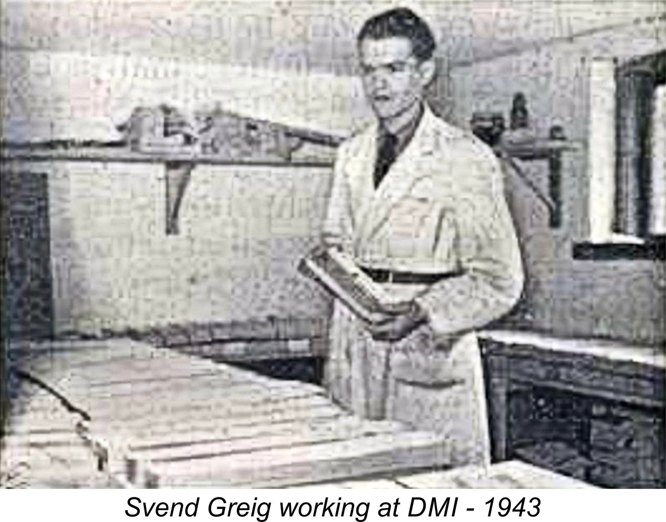 Greig’s new business was known as Dansk Modellflyve Industri (DMI - Danish Model Aero Industries). The venture began as a part-time business conducted out of Greig’s father’s attic, but soon expanded to the point where it became a full-time activity. In 1938, new premises were secured in Skern, with a further move being made in 1942 to the company’s final location in Odense, a city located in south-central Denmark on the island of Fyn. An interesting illustrated 1943 article (in Danish, but with an effective translation option) about the early years of DMI may be found
 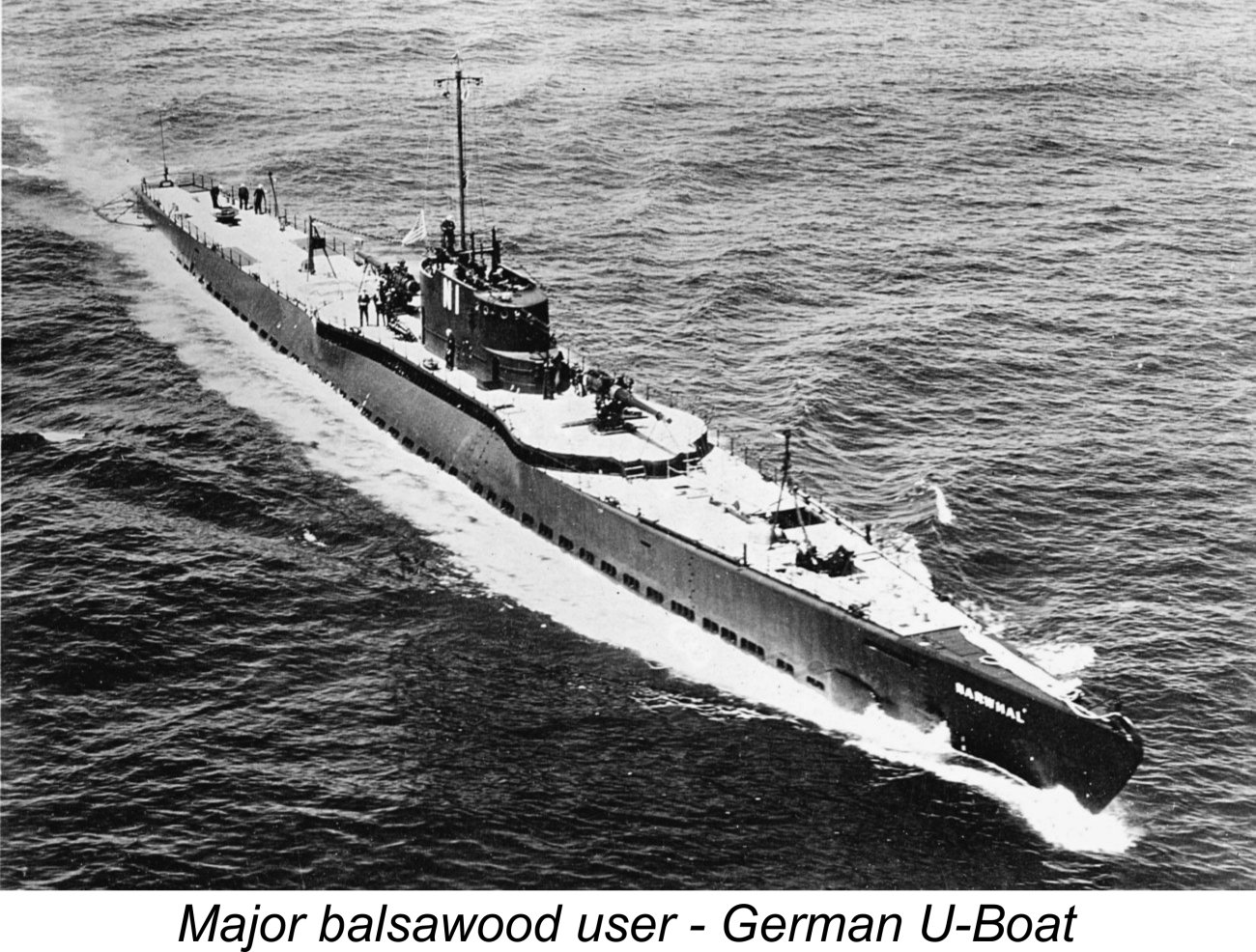 Interestingly enough, in that 1943 article Greig recalled that long after the war began he was still able to obtain supplies of balsa wood from Hamburg, Germany. He also obtained a variety of modelling materials through Sven Wentzel in Stockholm, Sweden.
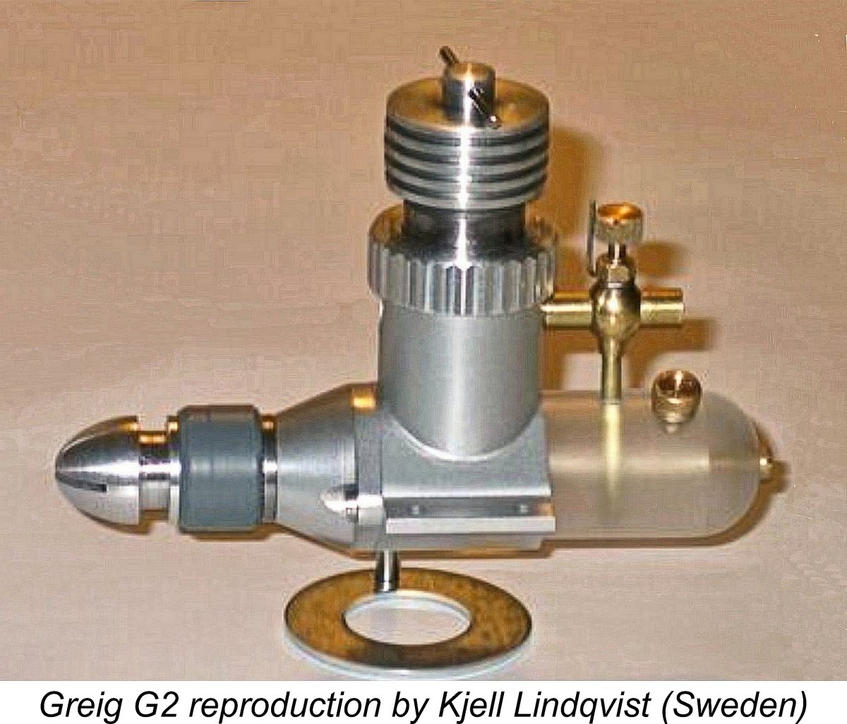 displacement, the 4.0 cc Greig G2 and the daunting 10 cc Greig G3. Later there was also a pioneering turbojet design which was not successful. The illustrated replica of the Greig G2 was made by my late and much-missed Swedish friend and colleague Kjell Lindqvist to his usual superb standard.
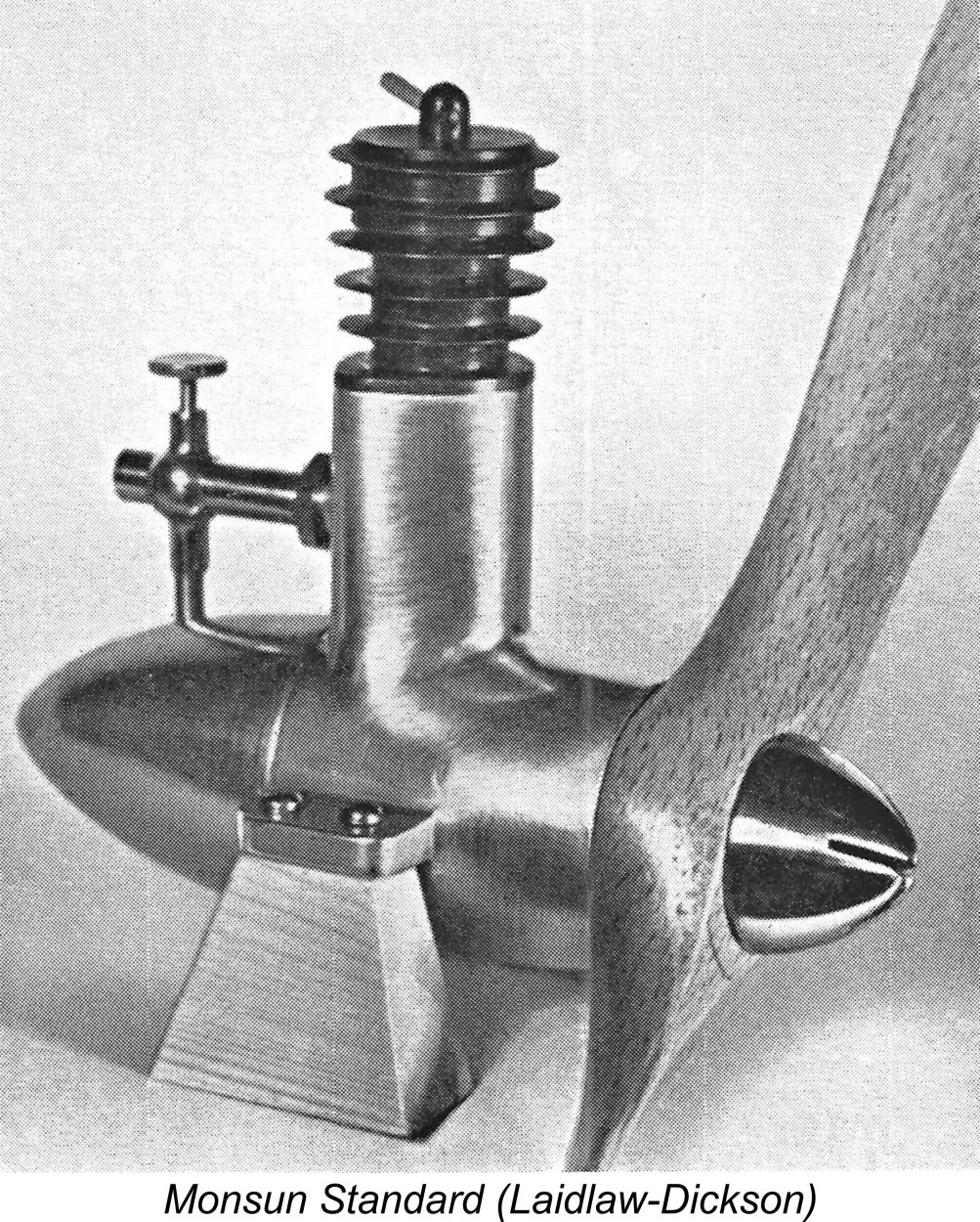 As one of Denmark's pioneering diesel users, Dommergaard soon developed some very definite ideas of his own regarding model diesel design. Beginning in early 1944 he began to collaborate with Jeppesen and Haugård on the design of a 2.4 cc sideport diesel which they called the Monsun (Monsoon) Standard. While still seemingly paying homage to the Dyno in basic design terms, the Monsun Standard was apparently just as strongly influenced by the Diesella, at least in terms of its external styling.
 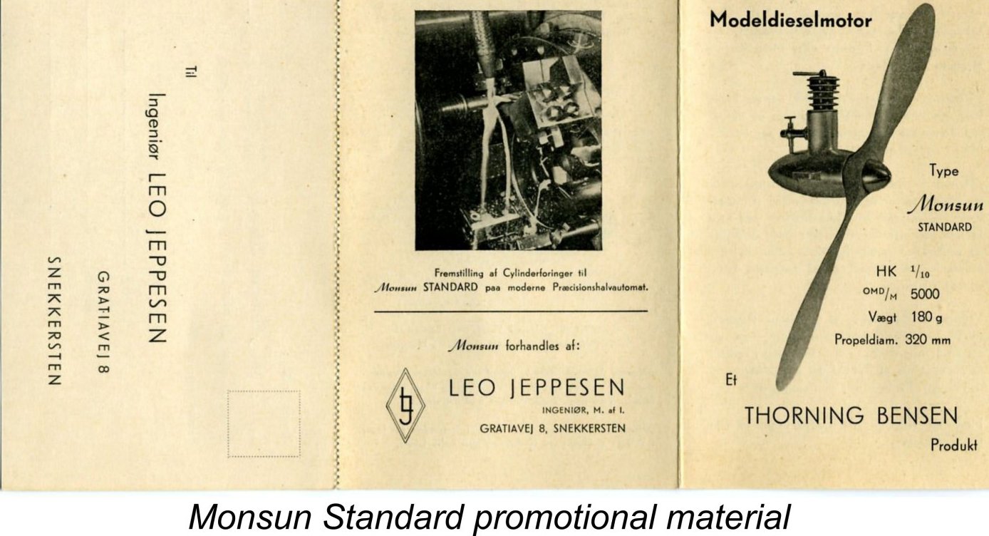 finished products.
 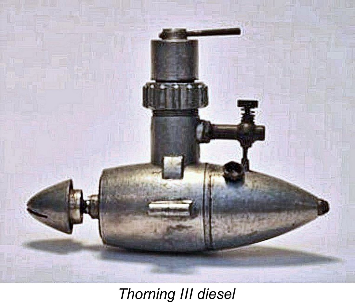 Thorning Bensen made some changes to this design in order to simplify its manufacture somewhat. He then made preparations to go into larger-scale production, acquiring some new equipment and taking on two additional workers besides himself. In late 1946 he began production of the engine with which his name is most widely associated today - the Thorning III sideport diesel. For reasons which are now obscure, the Bensen portion of the name was dropped at this time, never to reappear.
 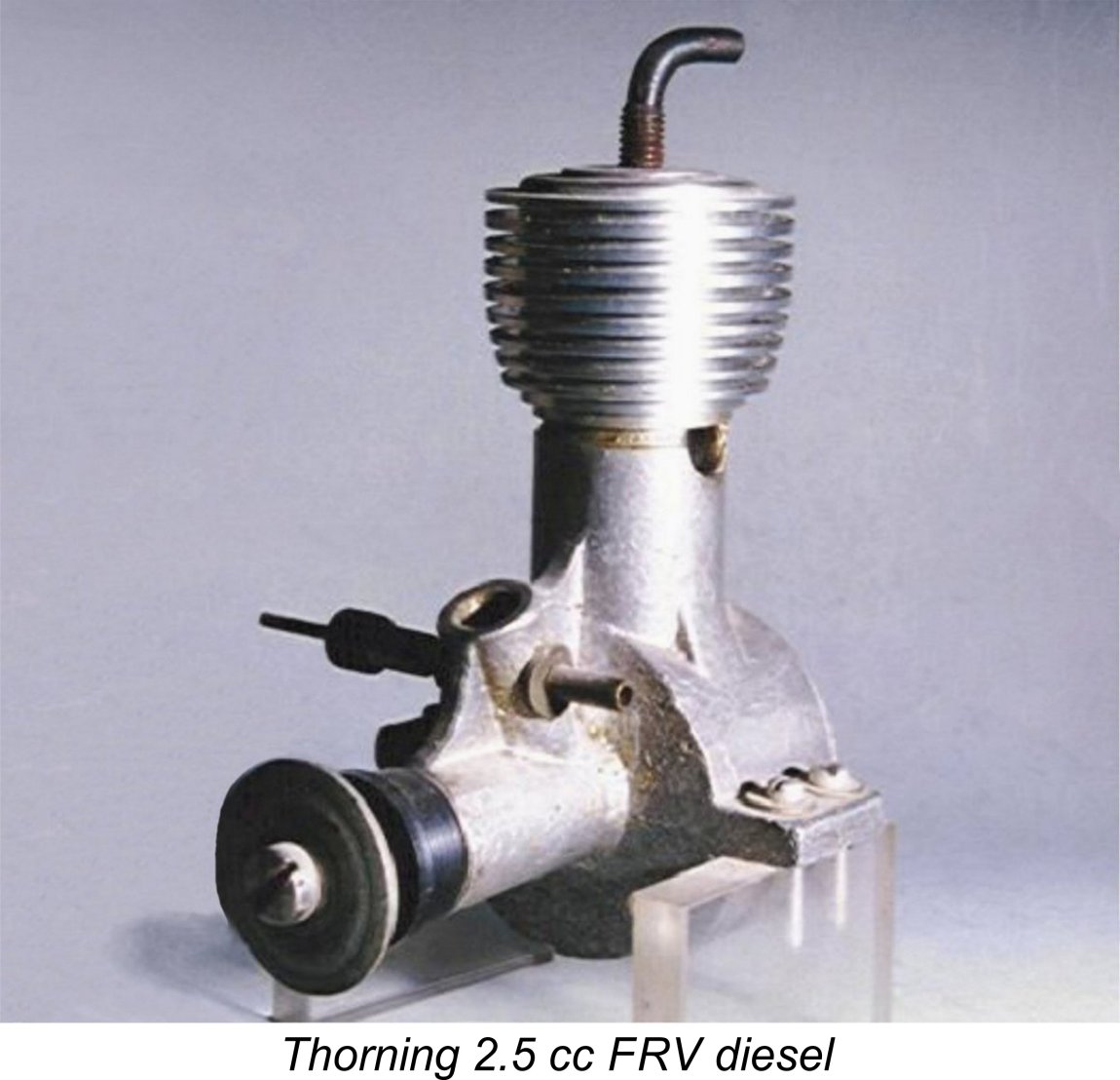 In late 1949 Bensen produced a prototype of a planned 2.5 cc crankshaft front rotary valve (FRV) replacement for the increasingly out-dated Thorning III sideport model. This appears to have been a response to the news of the incipient release of the competing Viking 2.5 cc design, of which much more below in its place.
 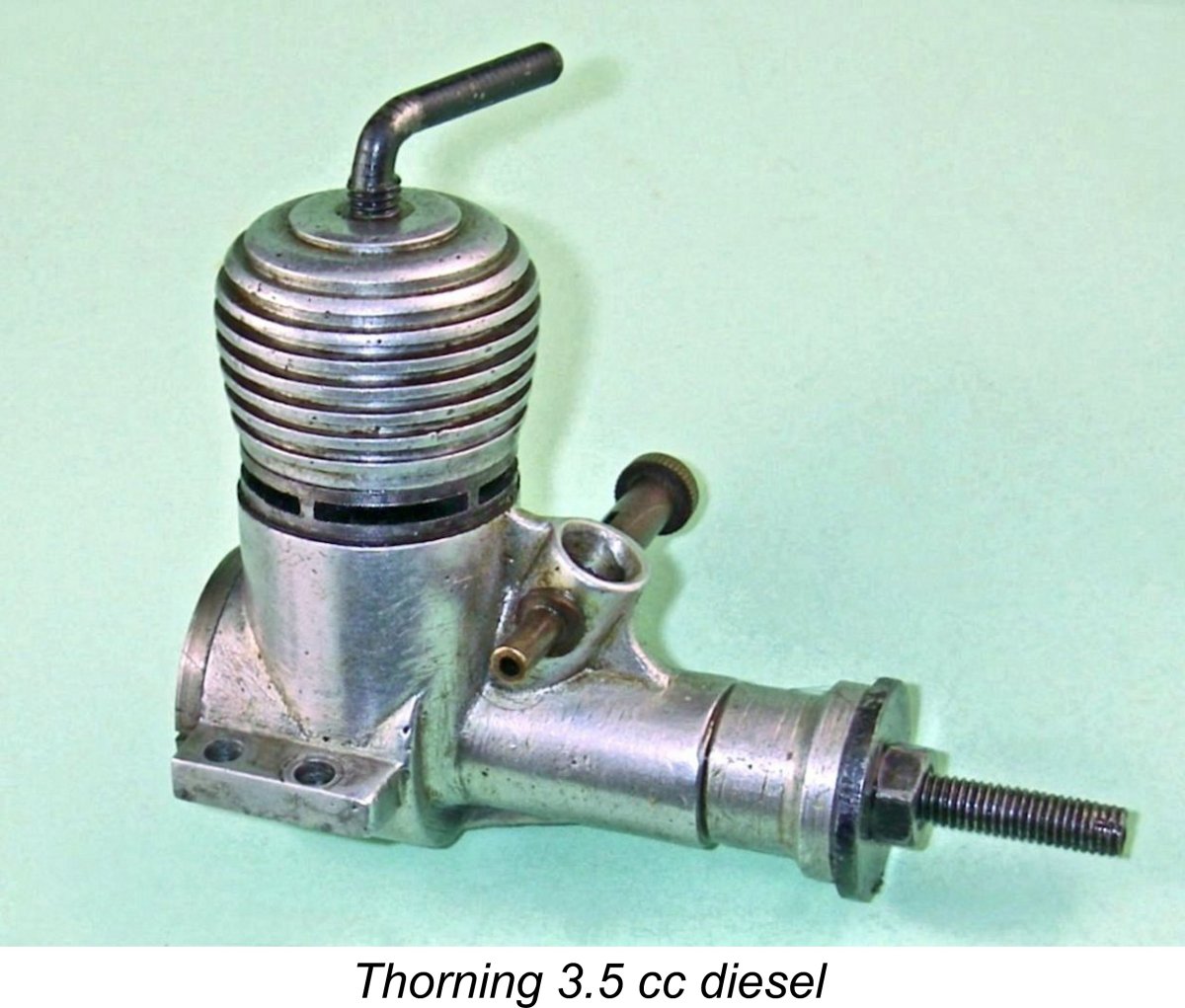 The resulting 3.5 cc model was closely modelled upon the design of the very successful AMCO 3.5 PB model from England. It made its appearance on the Danish market in the latter part of 1950. A full review and test of the
 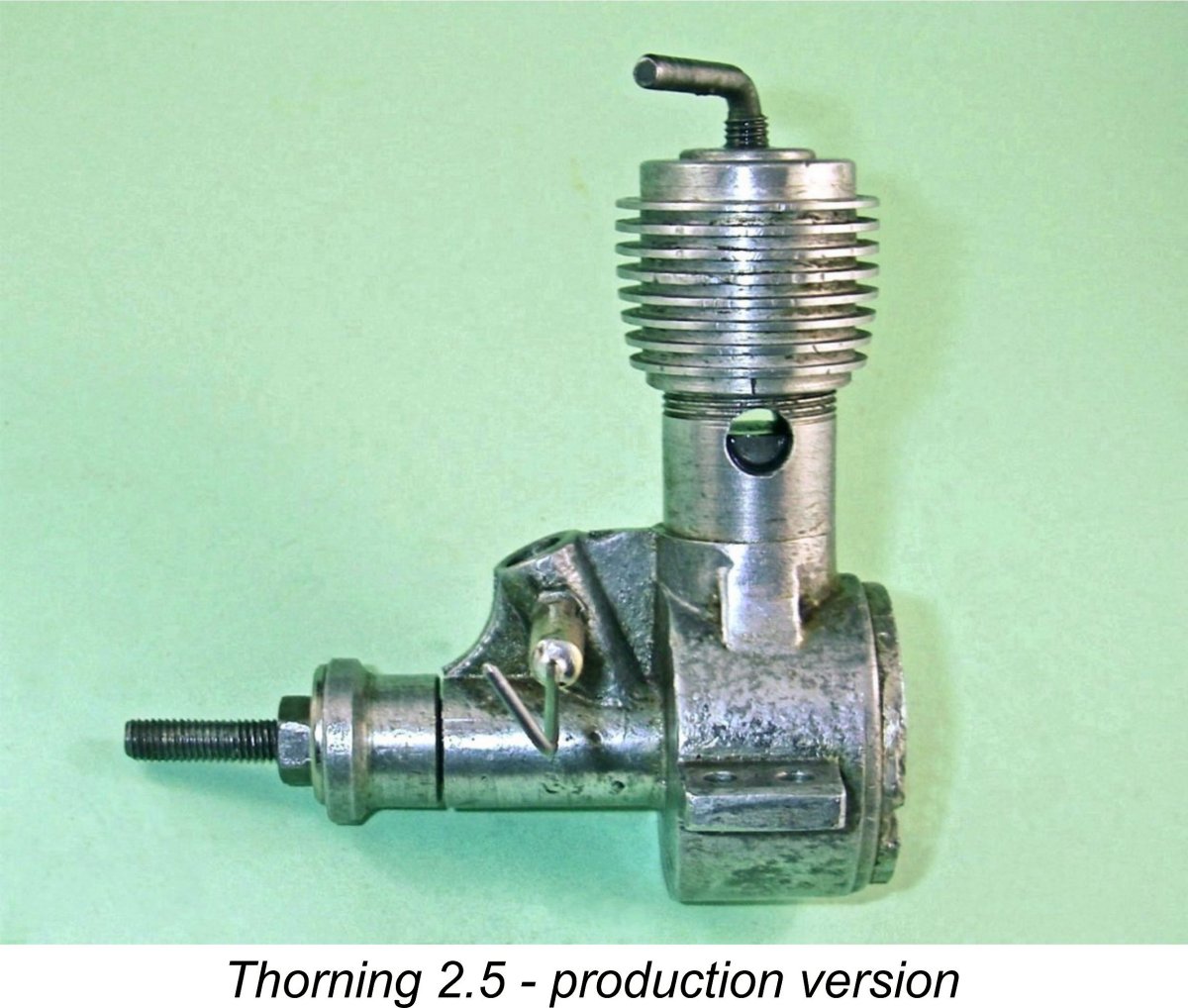 There were apparently some problems with the production of the required permanent molds, but by early 1951 the new 2.5 cc FRV design was finally judged to be ready for release to the public. Production of the venerable Thorning III ended at that point, or possibly a little earlier. Like its 3.5 cc companion, the new 2.5 cc model was identified simply by its displacement - the two designs were called the Thorning 2.5 and 3.5 respectively.
 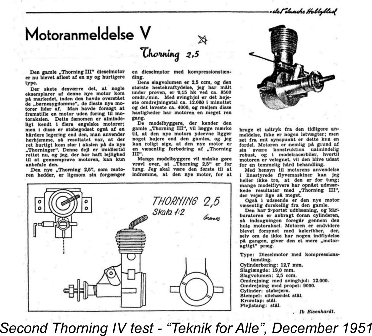 Thorning Bensen moved rapidly to address some of the concerns highlighted in this test, including the incorporation of a bushing in the main bearing. Although it was on the verge of ceasing publication, the Danish "Teknik for Alle" magazine nontheless hastened to get a condensed but still informative addendum report on this revised variant into its December 1951 issue (its last issue, as far as I'm aware). A slightly improved output of 0.152 BHP @ 8,500 RPM was cited in this test report, together with the observation that the main bearing wear issue had been satisfactorily addressed.
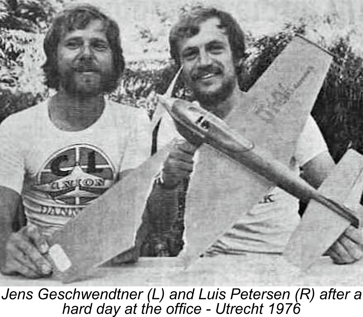 During the 1980’s, my valued Danish colleagues Luis Petersen and Jens Geschwendtner began to take an interest in the history of the Viking range. One of their goals became to assemble as complete a collection of the engines as possible for display in their local Technical Museum. Failing that, they at least wanted to find opportunities to examine and photograph representative examples.
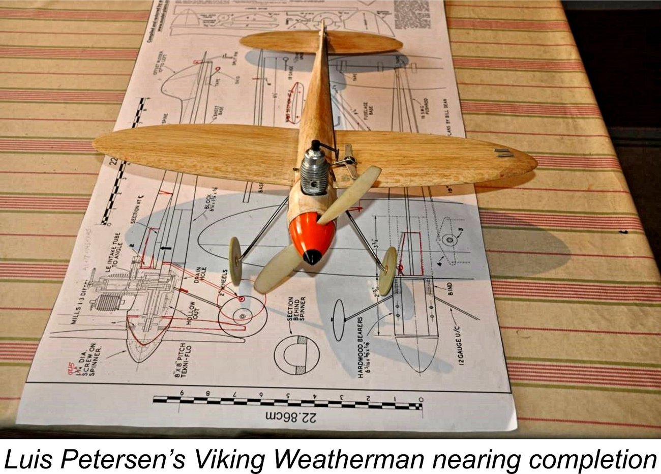 It turned out that he was a great source of information because he had been apprenticed at the workshop of Christian Tommerup Clausen (generally referred to as just Tommerup Clausen), who made the Viking engines. Those who have a Viking Red Helm engine may have noticed the letters CTC on the side?
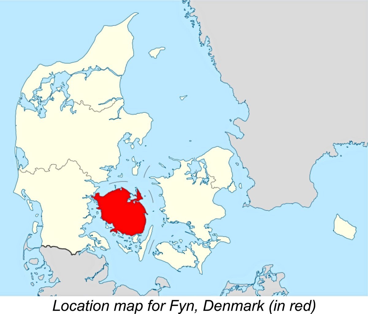 So the Viking marque remains alive and well on the flying fields of Denmark, 66 years after its establishment. No doubt Tommerup Clausen, who died a few years ago, would be very happy to know this!
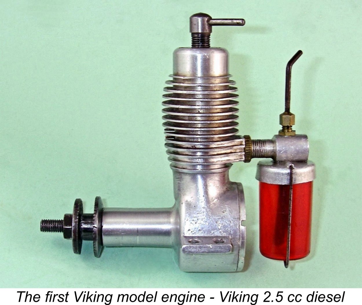 The first Viking engine, a 2.5 cc sideport design of which much more later, was constructed by Clausen at the beginning of 1950 following consultation with some members of the Odense Model Flying Club. It was inspired by the earlier Thorning III model and other similar designs, although it actually displayed considerable design originality. It’s an indication of the way in which Clausen worked at this time that the design drawings were made with chalk on the workbench! It was only in around 1958 or 1959 that the first proper engineering drawings were produced by one of the apprentices.
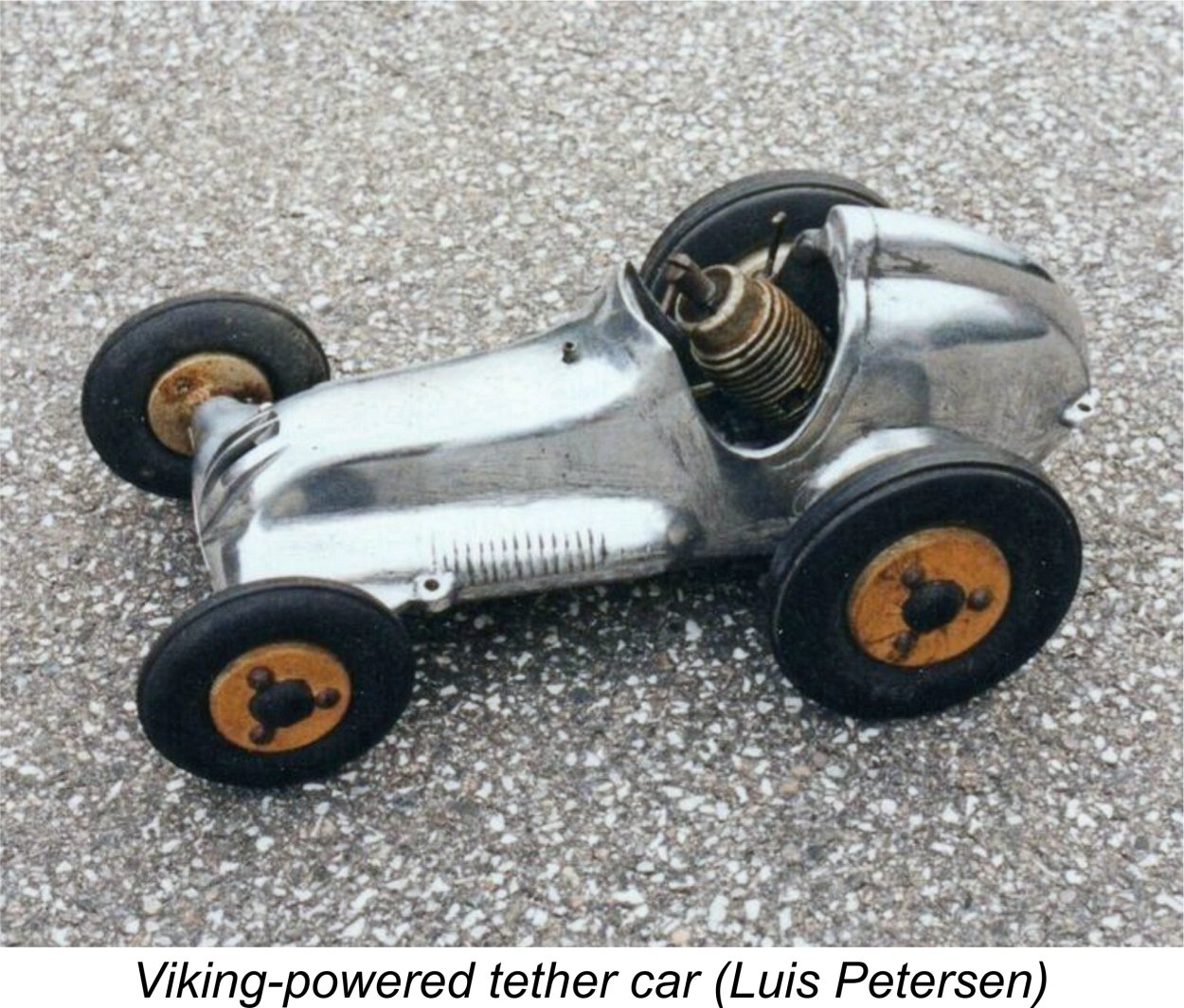 number of protruding wires of various lengths fixed to it. A given length and thickness of wire has its own resonant frequency at which it vibrates. Clausen established a standard for his engines, and each engine could be checked using this device to ensure that it met the standard by causing the appropriate wire to vibrate while running.
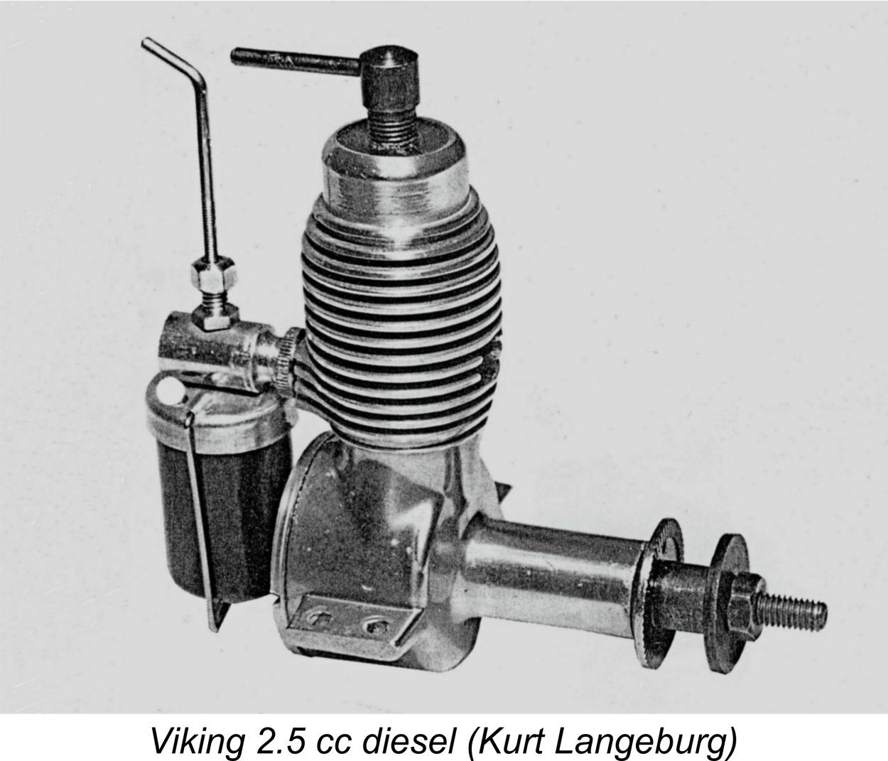 This well-made and in some ways considerably out-of-the-rut sideport model is the design for which the Viking name (and indeed the Danish model engine manufacturing industry) is best known today in the world outside of Denmark. It was both the first and last model engine produced by Tommerup Clausen’s factory, remaining in production throughout the life of the Viking model engine range from 1950 to 1969.
 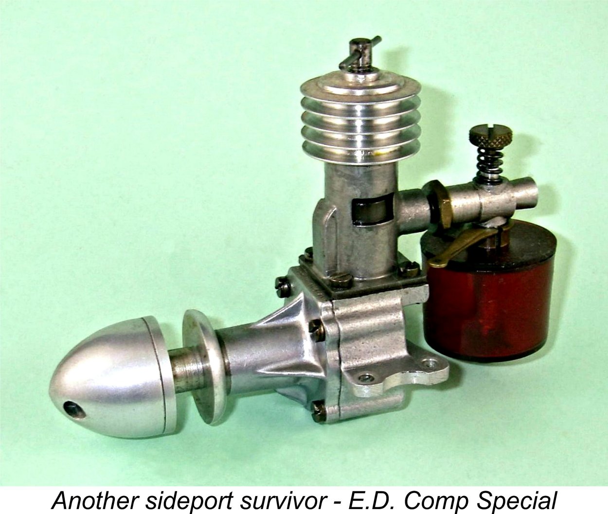 can think of were the
 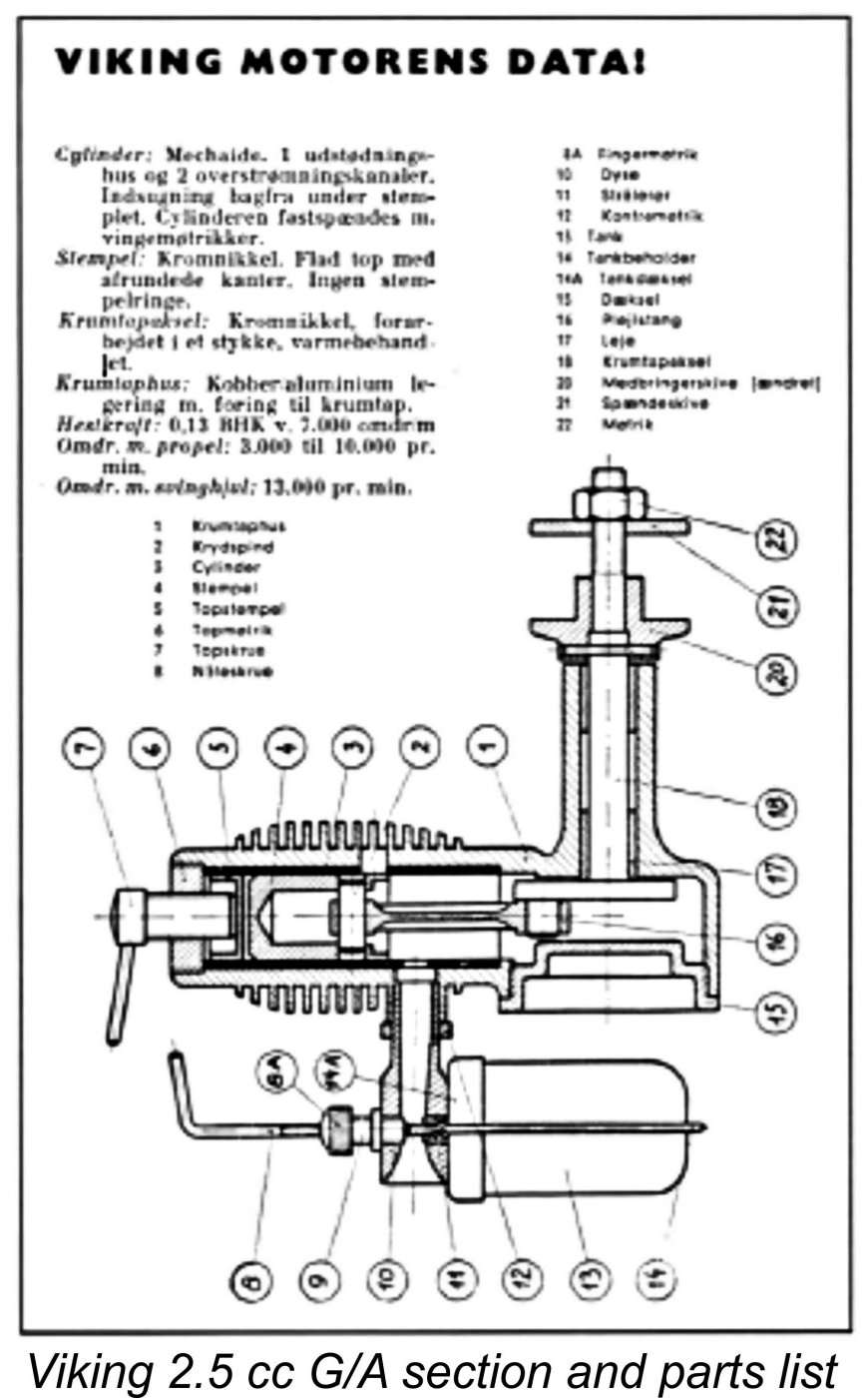 The cylinder porting design of the Viking was also copied more or less directly from that of the Thorning III. This included perhaps both models' most unusual feature, namely a single forward-facing exhaust port, which can be clearly seen in the attached images. This feature was well out of the rut in 1950, but it did reappeared much later in high performance Russian team race diesels. The intention there was to place the hottest region of the cylinder in the least obstructed direct cooling air-flow. It would of course have the same effect when applied to the Thorning and Viking designs.
 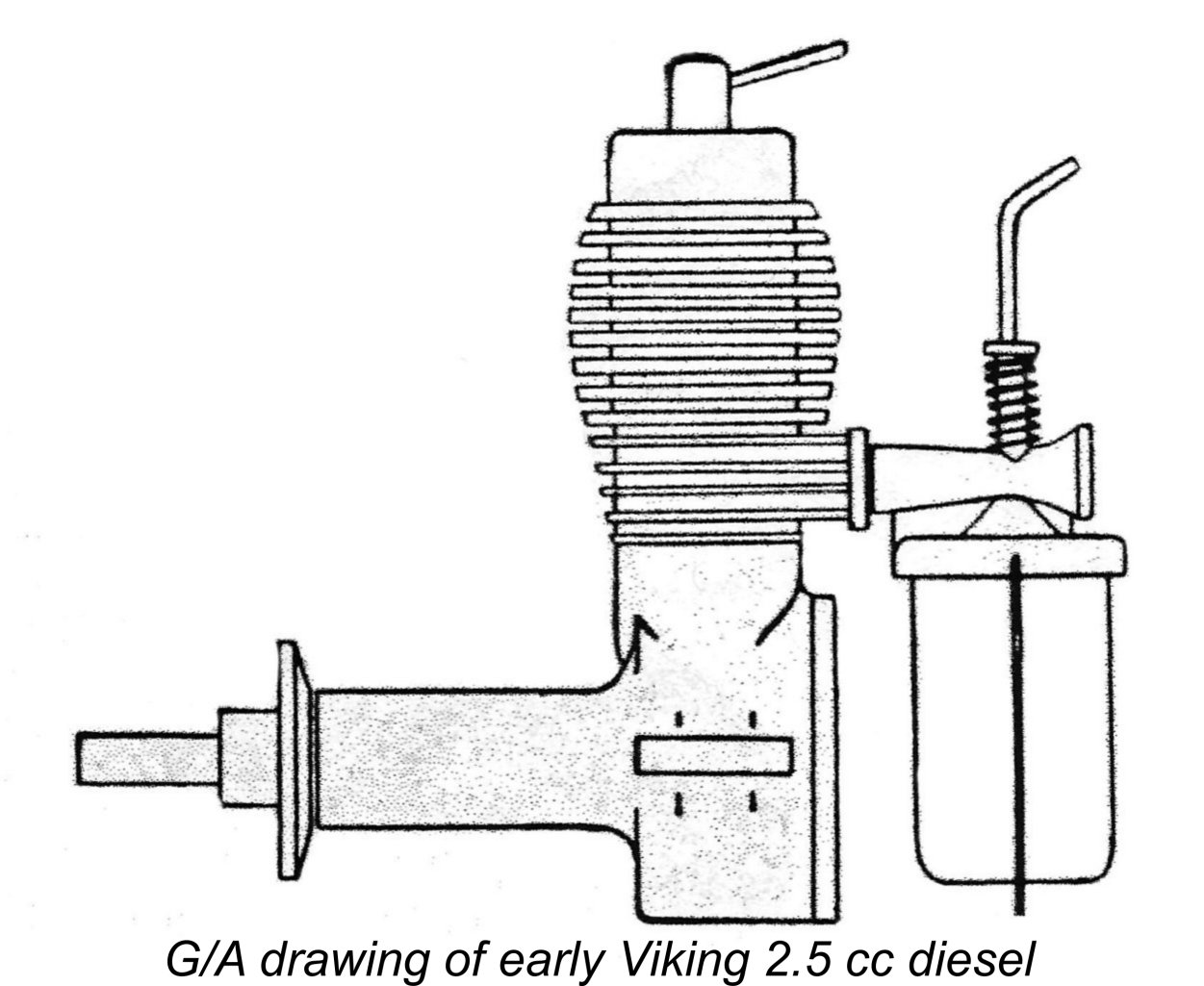 carrier for the needle. The needles used with this carburettor were fitted with a disc which bore against a coil spring fitted around the needle carrier to provide the required needle tension for security of settings. Hopefully this arrangement will be made sufficiently clear by the attached G/A drawing of one of these early models. The later section of this article dealing with the Viking 3.2 cc diesel shows an example of that model with the cast carburettor unit fitted - see below.
 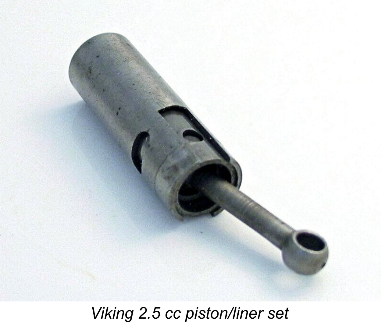 One criticism which may fairly be levelled at this point is the weight of the piston. That component together with its pressed-in gudgeon pin and steel con-rod weighs all of 16 gm. That's a lot of reciprocating weight for a long-stroke 2.5 cc engine like this, and one would expect this unit to be a serious vibration producer despite the counterbalanced crankweb with which the crankshaft is provided.
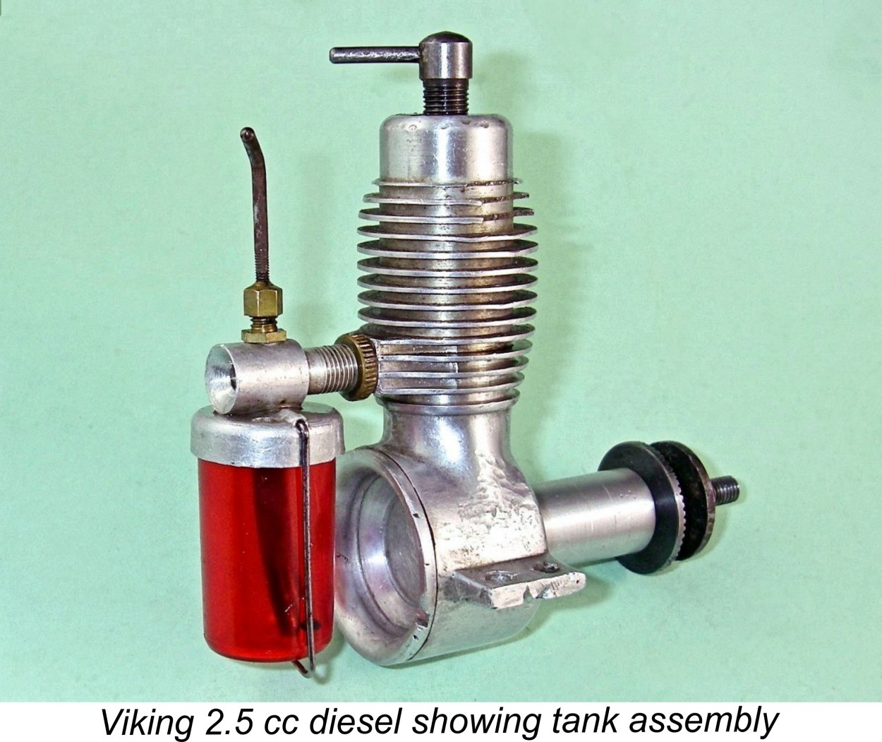 Throughout its long production life, the engine was little changed, implying that the designer got it more or less right at the outset. There were a few hiccups, however. The early models featured a light alloy prop driver which was secured with a pin through the shaft, but this proved to be inadequate since the stress concentration which it created led to a rash of broken crankshafts. The prop driver mounting arrangements were accordingly changed to a far more secure taper-on-shaft system with a steel prop driver. Incidentally, the original configuration was apparently copied directly from the Dyno 1.
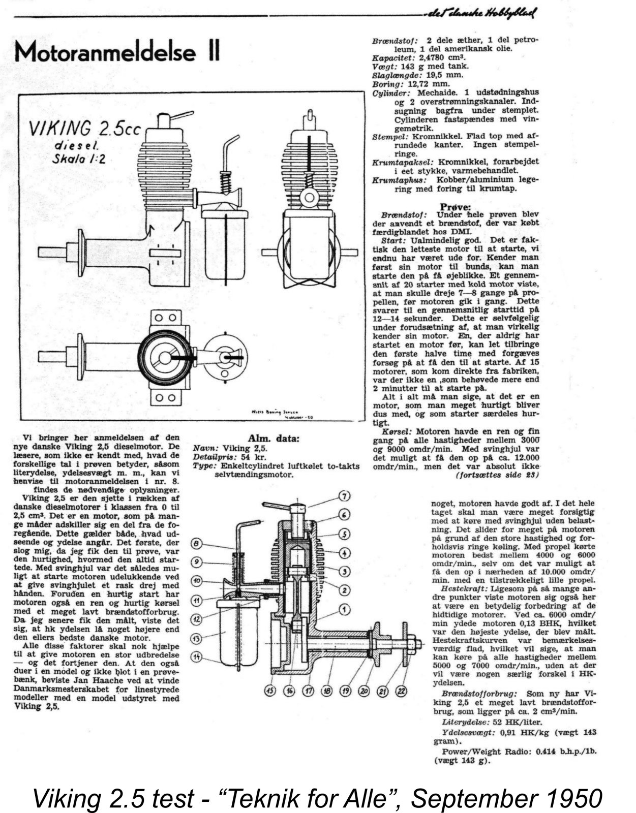 The Viking 2.5 cc diesel was the subject of a published test which appeared in the September 1950 issue of the previously-cited Danish magazine "Teknik for Alle". It was the second such test to be published in the magazine, as indicated by the Roman numeral "II" in the heading. This reinforces my earlier comment regarding the significance of the Roman numeral "V" in the heading of the later Thorning 2.5 test.
 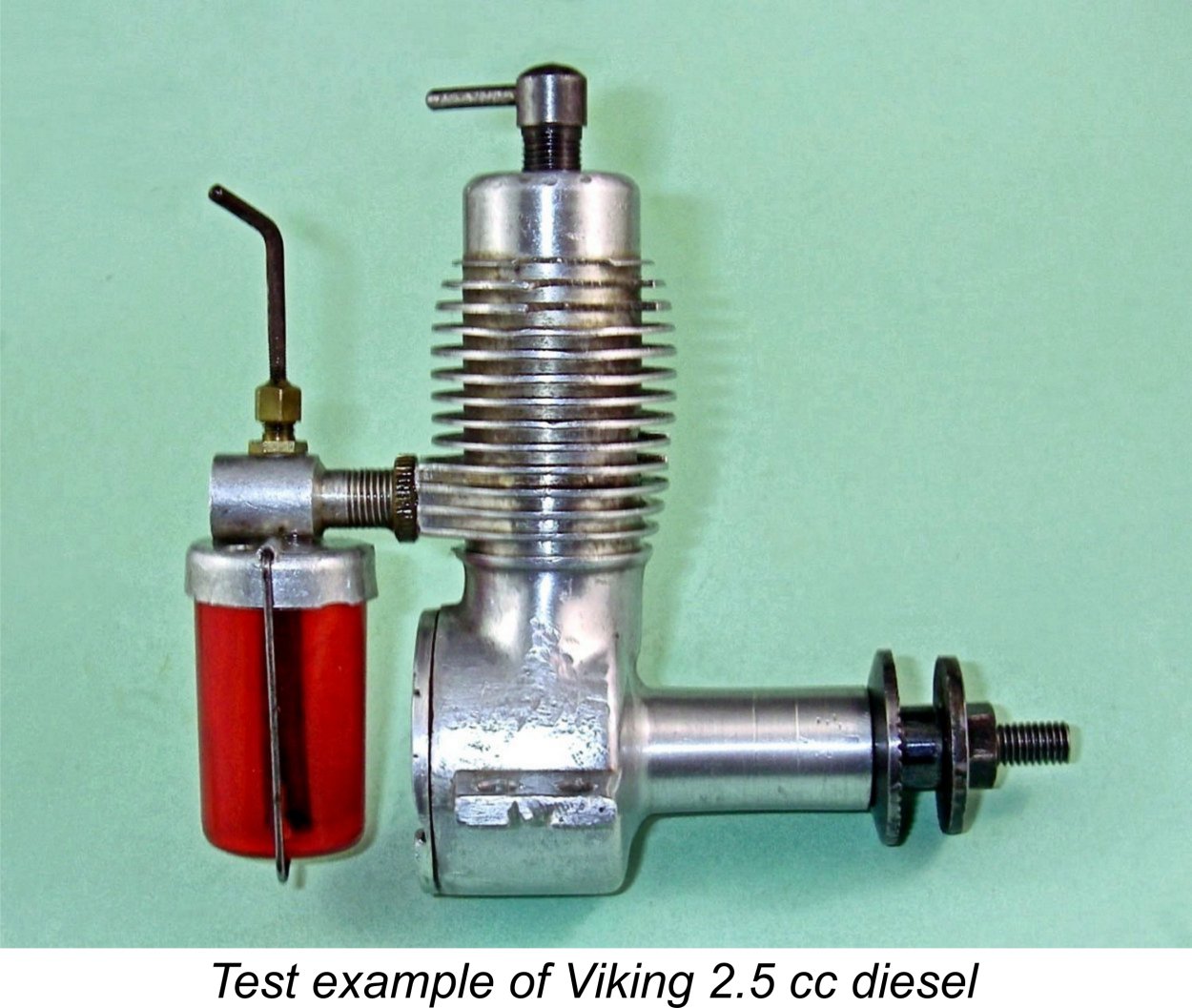 a club, but even so it should clearly be a much faster prop than any 11x6! The implication was that the engine peaked at a somewhat higher speed than 6,000 rpm! In my view, the limiting factor would probably be the vibration issue resulting from the combination of a very heavy piston and a very long stroke.
 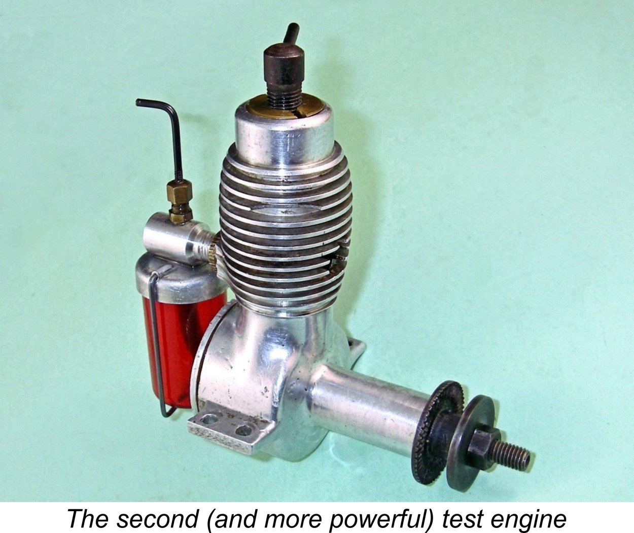 sense.
 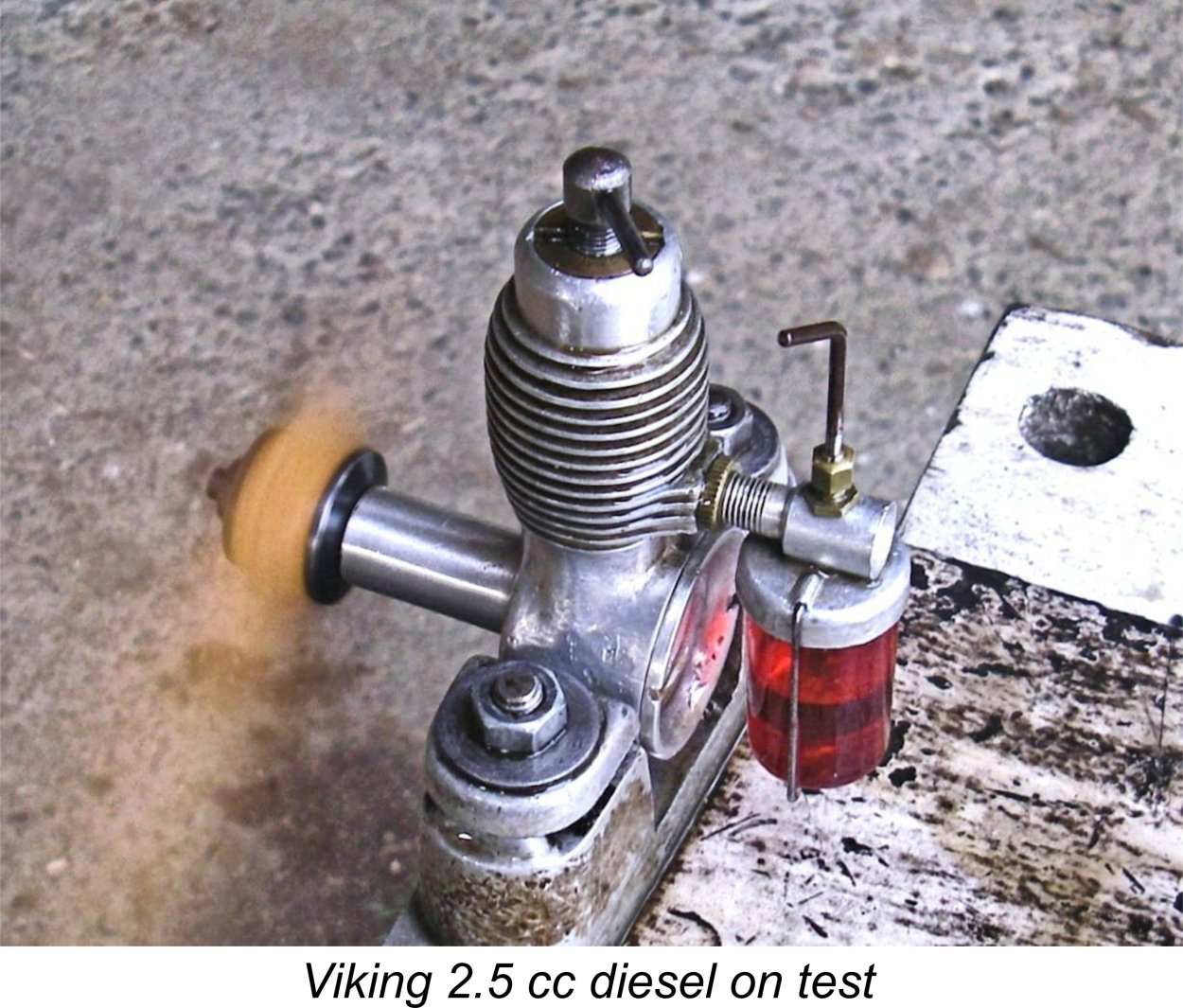 A few things soon became apparent. One, excessive choking was to be avoided during cold starting! I found that it was quite easy to flood the crankcase using this method. To get the engine going from cold, the best approach seemed to be to give a single choked flick to fill the fuel line and then administer a modest prime through the exhaust port. If this was done, the engine invariably started almost immediately. For hot restarts, the prime could be omitted.
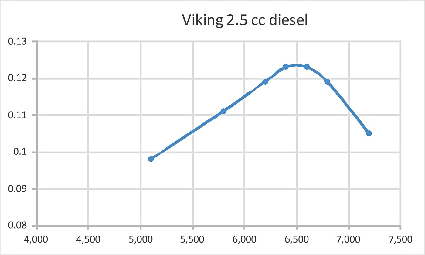
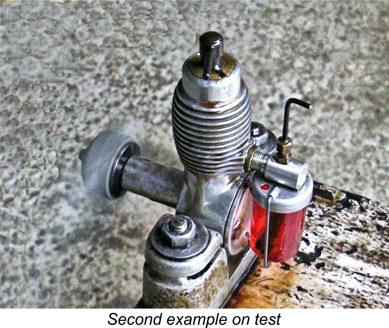
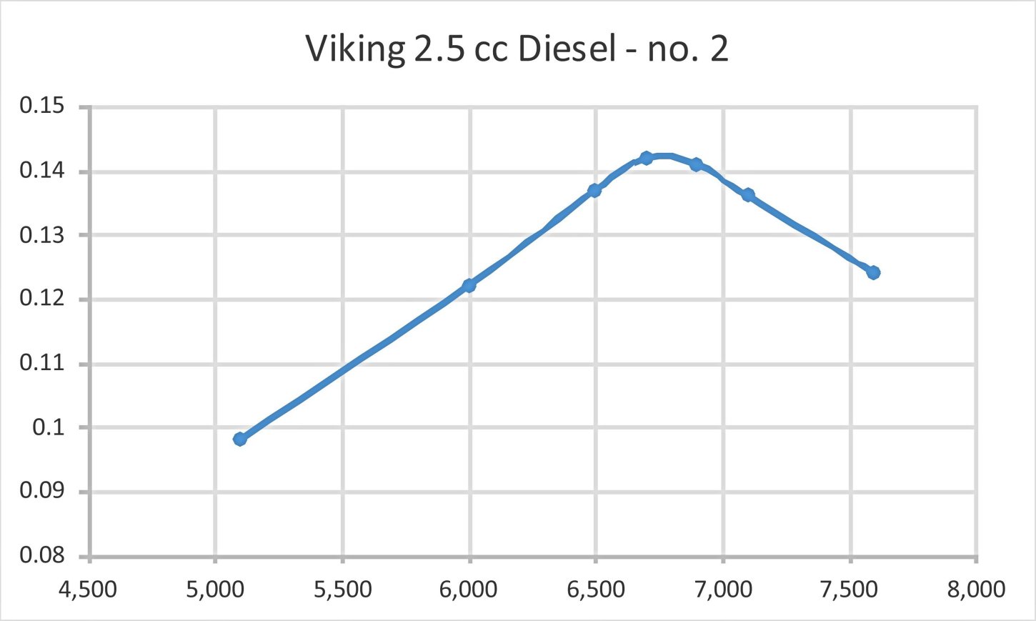
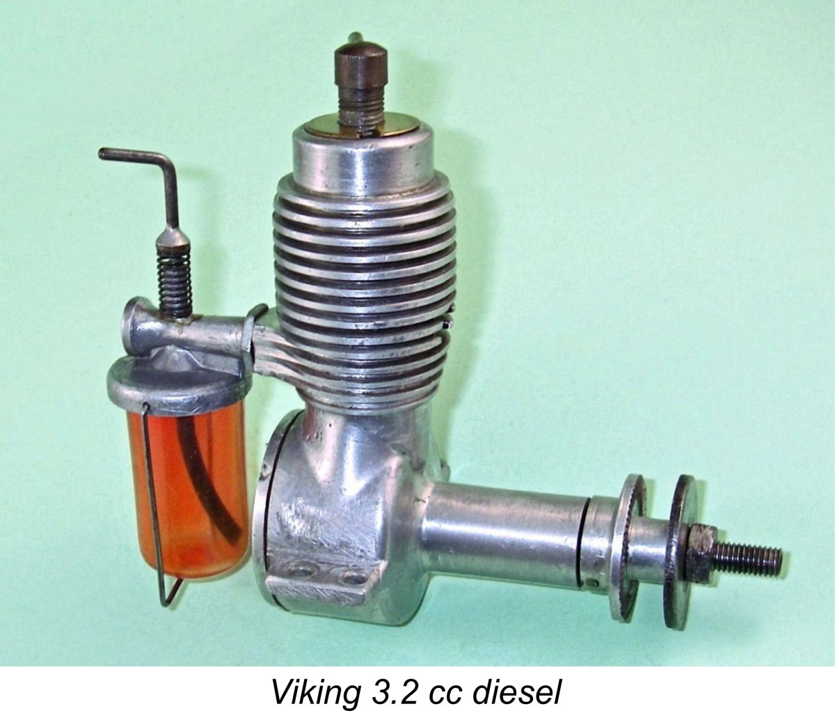 This is the model which started Luis’s previously-noted late 1980's quest for information. It was basically a bored-out version of the 2.5 cc engine described above, nominally retaining the same stroke of 19.50 mm but utilizing a larger bore of 14.4 mm for a displacement of 3.18 cc.
 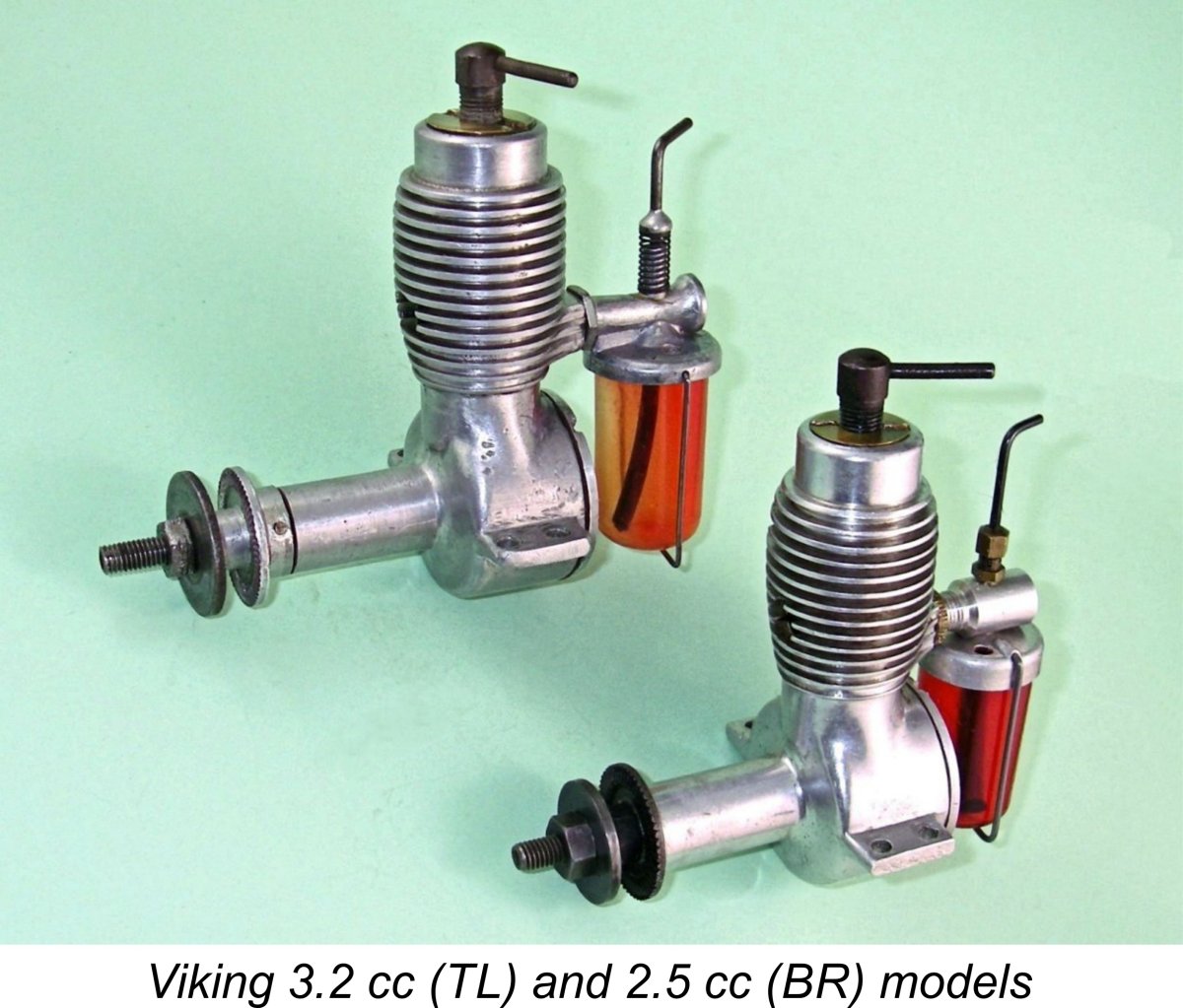 All examples of this engine were fitted with the original pinned alloy prop driver, also featuring the early combination of a cast carburettor and a blue plastic tank. As noted in our description of the Viking 2.5 cc model, the cast carburettor was all too prone to breakage, and this example is no exception - the needle carrier has been broken off at some point in its previous history. The necessary repair has been very neatly effected using an adhesive of some kind. The original blue tank has been lost and has been replaced with a later red plastic component. Apart from that, the engine remains completely original.
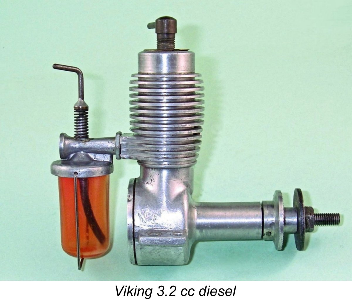
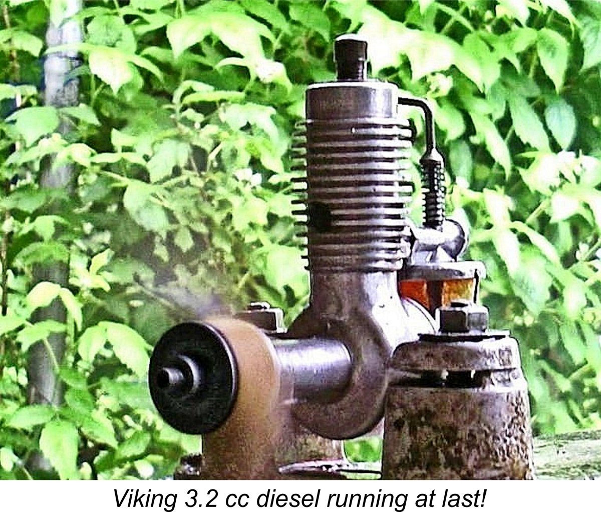 All of this left me with only a few hours available before the deadline! Even so, I set the Viking up again with the intention of doing a quick 'n dirty test for this article. The engine proved to be quite well worn, with rather "soft" compression seal around the power piston. I found that as with one of my tested 2.5 cc models, an oil prime really helped when it came to starting, although the engine would start without that treatment. Despite the handicap of the soft compression, I'd rate this as every bit as good a starter as its 2.5 cc sibling. The same technique of a single choked flick and a prime was the way to go.
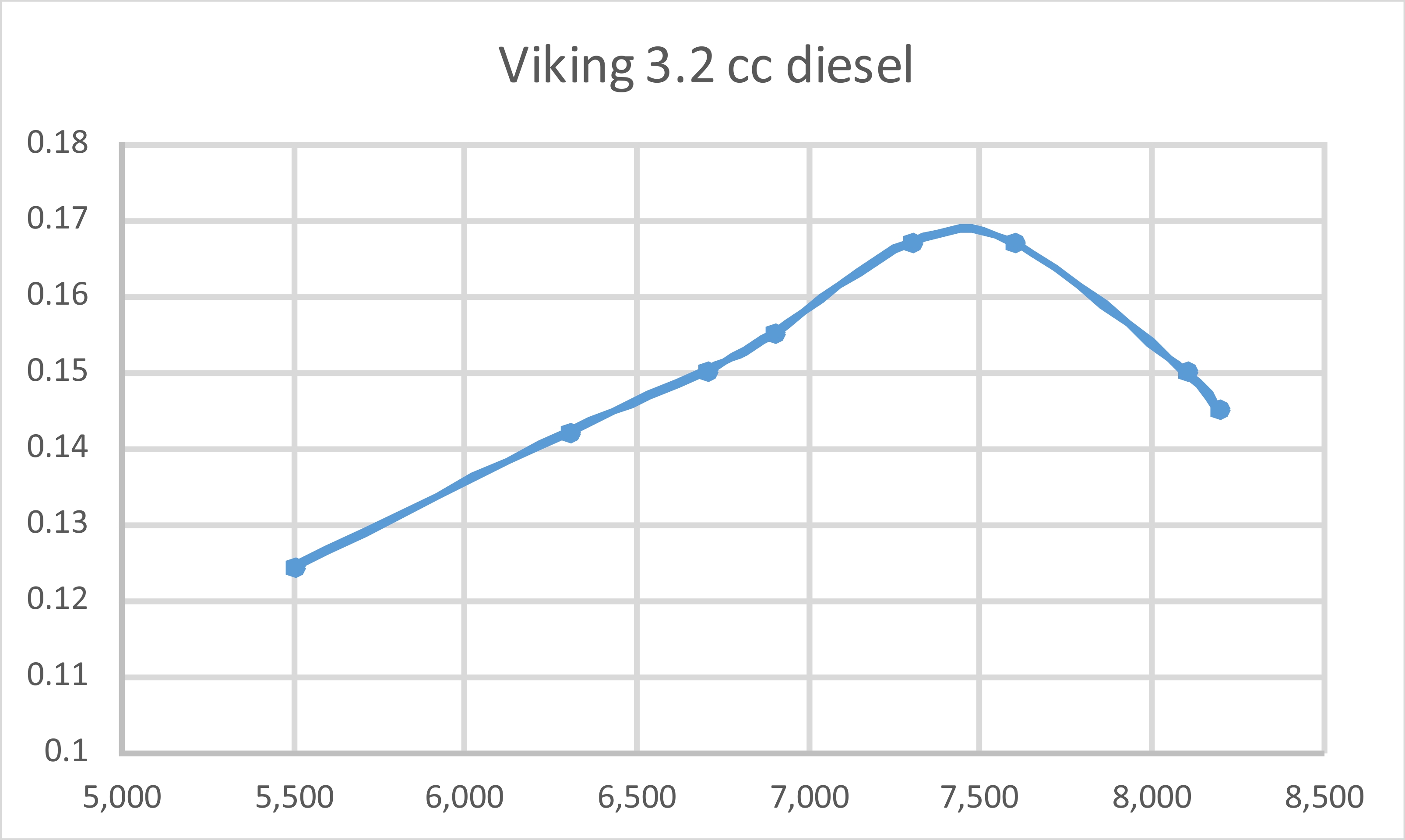
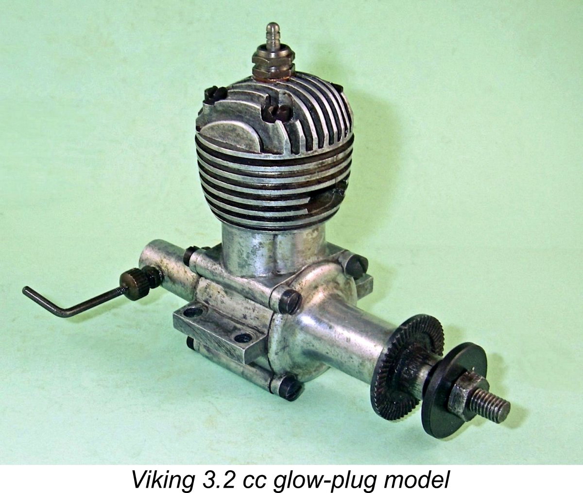 This design represented Clausen’s first step towards the modernization of the Viking range. It was a graceful glow-plug motor of generally up-to-date design featuring rear disc valve induction and reverse-flow scavenging. It retained the unusual forward-facing exhaust port location which had characterized the earlier diesel models, but took practical advantage of the absence of the sideport induction tube by adding a second matching exhaust port at the rear. Both exhaust ports were unusually large.
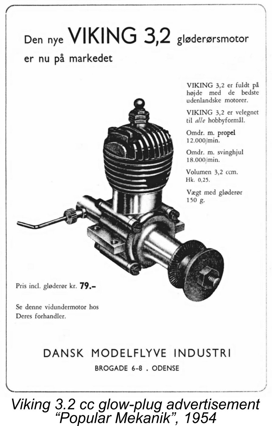
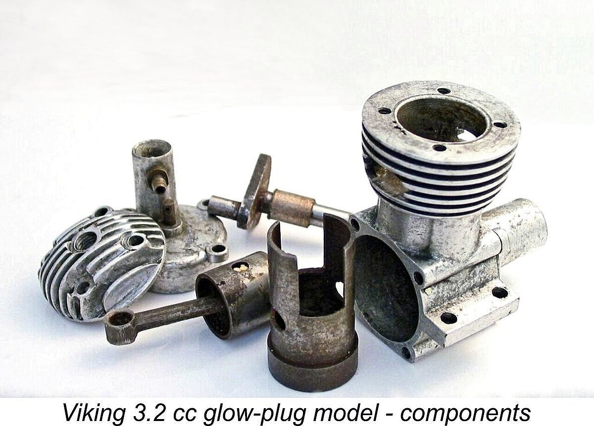
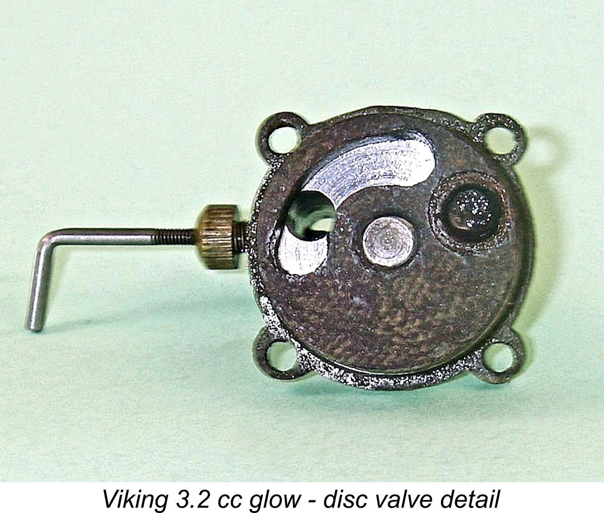
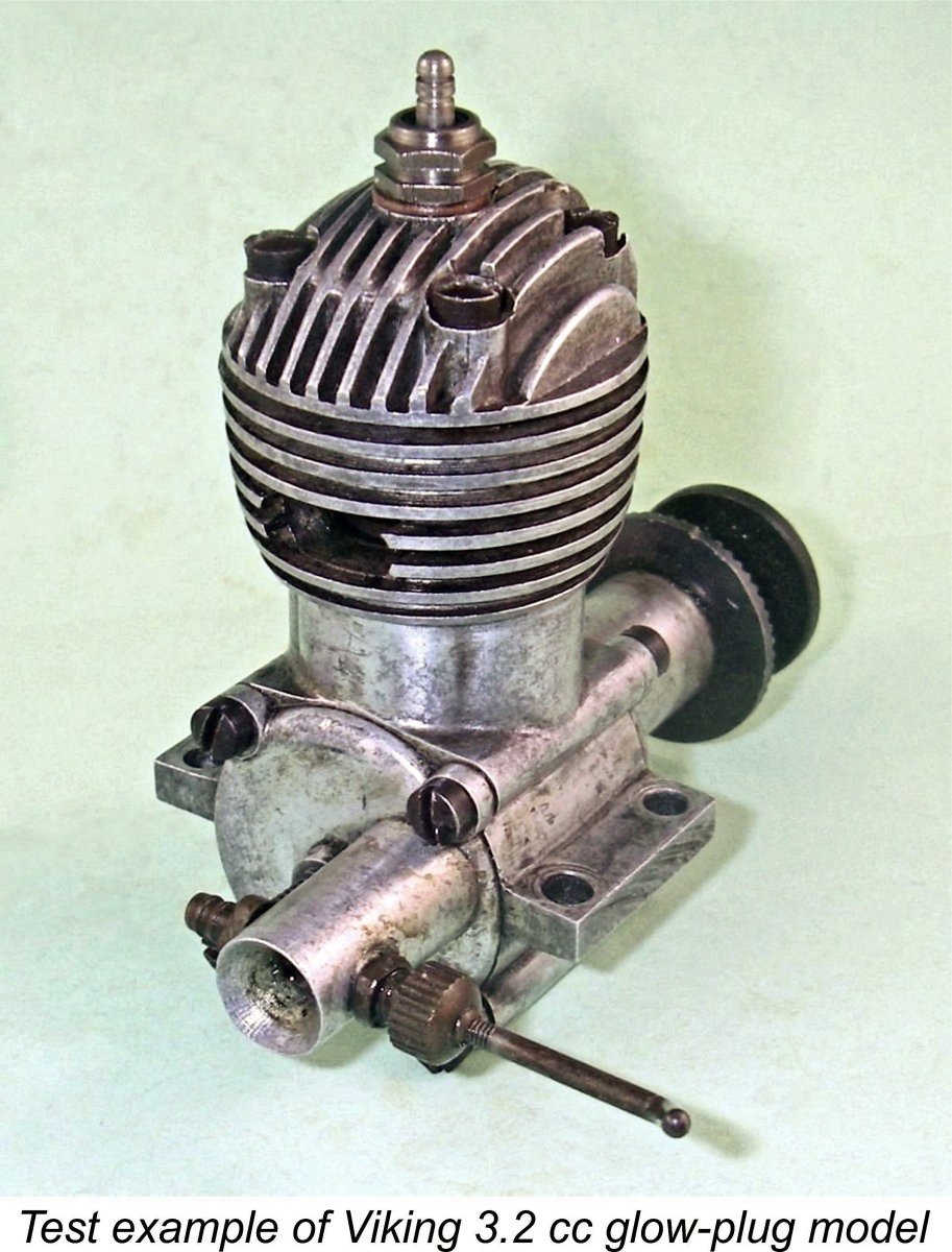 Some time after the original publication of this article, I finally got around to testing the fine example of this very rare engine that had been so kindly supplied by Luis Petersen. I used a "hot" plug in deference to the engine's rather low compression ratio. Since most Danish modellers in the early 1950's would have had very limited access to high-nitro fuels, I went with a 10% brew. Even that was probably somewhat on the high side .........
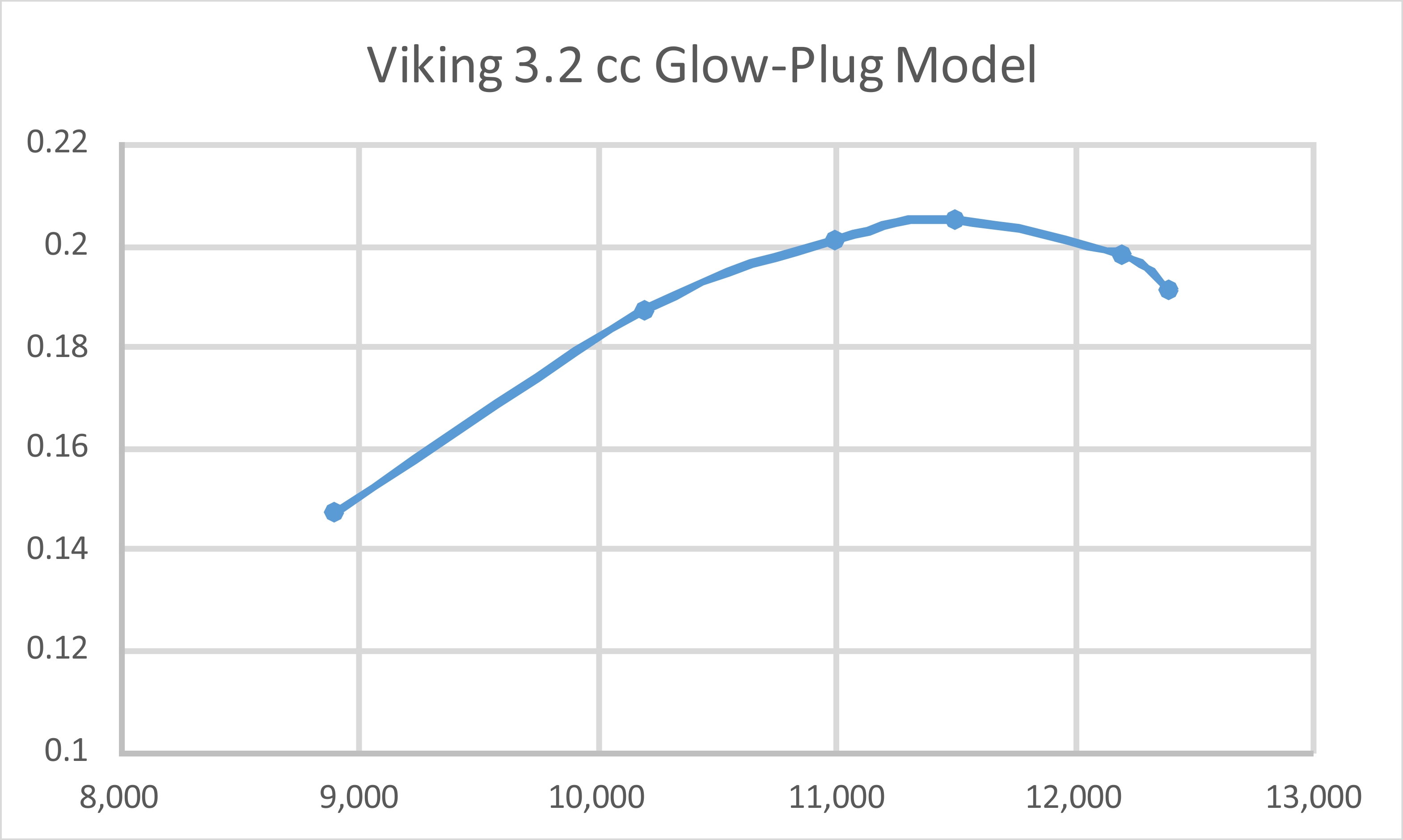
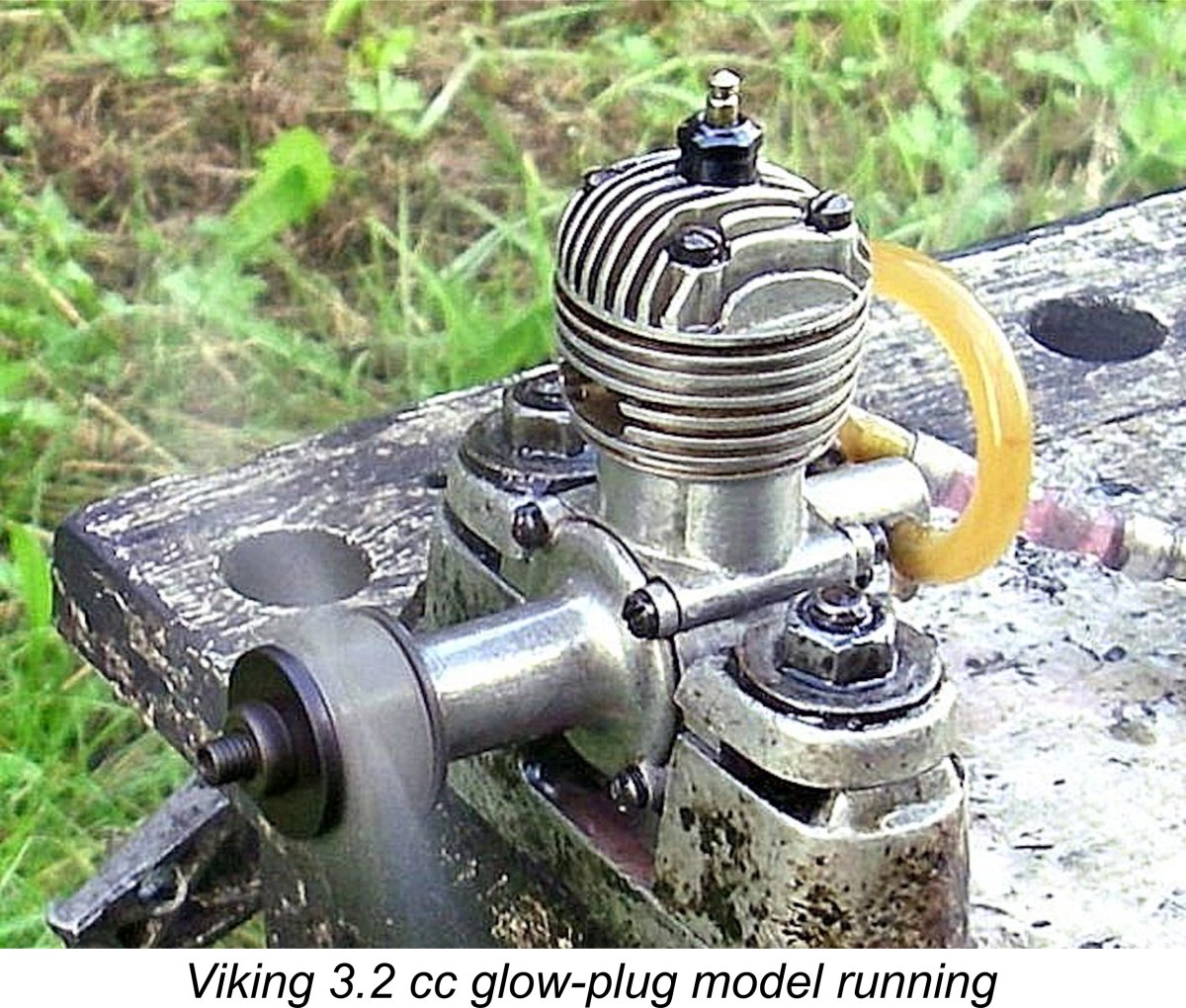
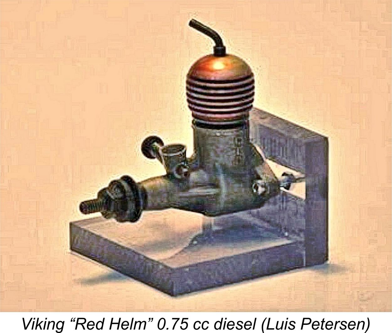 Readers who are familiar with American diesels will have spotted this one right away as more or less a direct copy of the 1953
 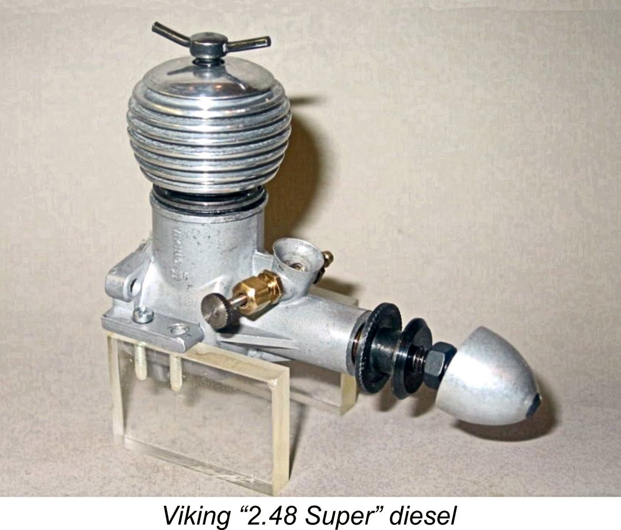 In 1956, Clausen introduced a 2.49 cc model called the Viking 2.48 cc Super which was in effect an enlarged version (without the red head) of the Red Helm 0.75 cc design which had been introduced in January of the previous year. The engine actually bore a marked similarity to the contemporary Webra engines from Germany.
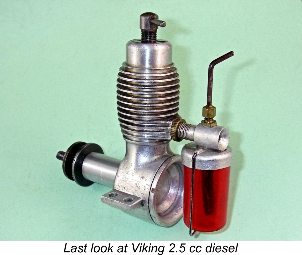 This almost certainly explains the fact that by the end of 1963 that original 2.5 cc diesel was the sole member of the Viking range to remain in production. The fact that it survived for another 6 years all the way to 1969 is a testament to its qualities in the eyes of the Scandinvian modelling community. Indeed, it is mainly the success of that model that has given the Viking range the honoured place that it holds today in Danish aeromodelling history.
| |