
|
|
American Class Act - the C.I.E. 10 Diesel
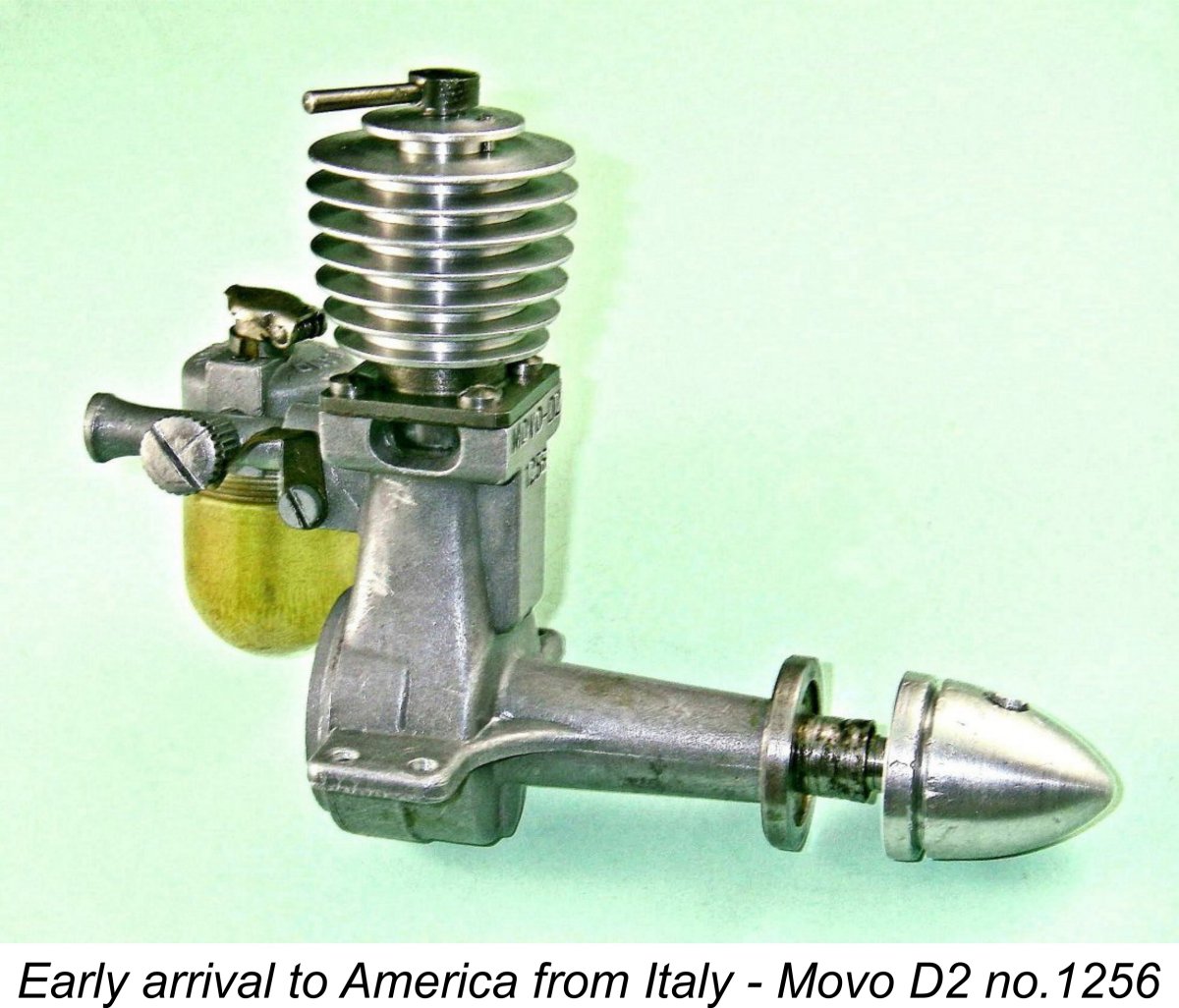
An earlier article on the late Ron Chernich's now-frozen "Model Engine News" (MEN) web-site presented some very useful information on this engine. However, further research and testing has since generated a substantial amount of additional data. Hence the need for this updated article, which appears here solely because the MEN site became frozen with the tragic 2014 passing of my good mate Ron. The original C.I.E. page remains available on MEN for perusal by those interested, and our sincere thanks are due to It's also both a duty and a pleasure to pay tribute to the late David R. Janson (1930 -2011), whose long-running series of articles on the history of a large number of classic model engines appeared in the newsletter of the Denver, Colorado chapter of the Society of Antique Modellers (SAM), subsequently being compiled into a privately-published and now very rare book entitled "Model Engine Designer and Manufacturing Profiles". The previously-linked MEN article includes the text from this book which dealt with the C.I.E. 10, with the permission of David Janson himself. For that reason alone, the MEN article remains well worthy of perusal. We are in David's debt for his efforts in preserving and disseminating this information. Finally, it would be quite impossible to write with any authority on the history of any American model engine without paying tribute to my good friend Tim Dannels, publisher of the sadly now-discontinued "Engine Collector's Journal" (ECJ) and author of the indespensable "American Model Engine Encyclopedia" (AMEE), now in its second updated volume. I could write for the next fifty years and still not equal the amount of information that Tim's efforts have preseved for us. No article such as that which follows could be written without frequent reference being made both to ECJ and AMEE. Thanks, Tim - your efforts are greatly appreciated, mate! As usual, we'll begin with a summary of the background to the introduction of this excellent model diesel. Background The model diesel (or more correctly, compression ignition) engine was a wartime European development which entered a rapid and very productive development phase in the years immediately following the conclusion of WW2. At the time in question, the miniature glow-plug had yet to be developed into a commercial form. Consequently, the early post-WW2 model diesel powerplant was competing only with the well-established spark ignition models for market attention. The fact that the model diesel did not require a heavy and potentially undependable airborne ignition support system gave it an obvious advantage over its spark ignition counterp Naturally, these advantages were as obvious to American modellers as they were to their European colleagues. As a result, by late 1946 America was becoming engaged in what was to prove to be a relatively brief but surprisingly productive flirtation with diesels, largely on the strength of experience with European examples brought back by servicemen returning from trans-Atlantic service in WW2. Impressed by the performances put up by the best of these imported European diesels, such as the illustrated MOVO D-2 from Italy, a number of US manufacturers decided to enter the model diesel market with home-grown designs of their own. A detailed account of the MOVO D-2 and its influence in America appears elsewhere on this website.
In addition, a number of other manufacturers including Thermite, Delong, AHC, EDCO, Ken, Strato and Queen Bee (the latter two in Canada) experimented with diesel models which do not appear to have made it into commercial-scale production despite showing considerable promise in some cases. All in all, the number of North American manufacturers having some involvement with diesels during the early post-war period was at least comparable to the number of such firms active in Britain at the time, a fact which may surprise many of my diesel-minded readers. I've presented a overview The C.I.E. 10 which is our present subject was one of the earliest of these post-war American diesel efforts, being preceded as far as I'm presently aware only by the almost-forgotten Thermite model which I've covered elsewhere along with the later Vivell diesels designed and manufactured by Thermite designer Jim Brown. In many respects, the C.I.E. was also among the best early post-war American designs, especially when viewed in the context of its times. The manufacturers of the C.I.E. identified themselves as the Compression Ignition Engines division of Modelcraft Hobbies of 11929 South Western Ave., Los Angeles 44, CA. Modelcraft were a major model goods distribution house, and the manufacture of model engines was very much a sideline for them. According to research carried out by the late John Pond, the actual designers and builders of the engine were a pair of gentlemen named Barney Snyder and William (Bill) A. Ruff. The engines were of course distributed through Modelcraft. Description of Variants It can’t be denied that the C.I.E. was a very attractive and well-made engine which could stand comparison with the majority of its early post-war European counterparts. The quality of the gravity die-castings (in 356 aluminium casting alloy according to data published in the January 1948 issue of “Model Airplane News”) was above average by the standards of the day. The machining was also carried out to very high standards, with excellent fits all round. Most contemporary European modellers would have been very happy to use this engine. It's actually a great pity that it was never marketed in Europe, since it would probably have been quite well received.
A straight-armed compression lever was used on this variant. The mounting lugs were located on the thrust line of the engine, and a screw-in backplate was employed. This early version had 11 fins on the cooling jacket instead of the later 10. I used the term “seemingly” in the above paragraph because no examples of this version are currently known to exist - its sole recorded appearance was in the original 1946 introductory advertisement for the C.I.E. 10. It’s actually likely that the illustrated example was an unreleased prototype. The cited displacement was 0.103 cu. in. (1.69 cc), somewhat less than that of all known examples of the engine in its more common form but at least consistent with the engine’s name. No bore or stroke figures were provided, and in the absence of any examples to check this anomaly cannot now be resolved.
The displacement was now cited as 0.144 cu. in. (2.36 cc). This displacement is very slightly at variance with the manufacturer’s claimed bore and stroke measurements of 0.50 in. (12.70 mm) and 0.75 in. (19.05 mm) respectively. These figures check out as nominally correct on actual examples, but they yield a calculated displacement of 0.147 cu. in. (2.41 cc). Perhaps the old abacus was a bit off-song that day .............! Checked weight was 179 gm (6.31 ounces) complete with tank. Despite the displacement inconsistency, the 0.147 cuin. engine continued to be sold under the C.I.E. 10 designation. These variants had either “CIE” or “CIE 10” stamped on a flat surface which was machined onto the fr It has even been suggested that this treatment was necessary to remove cast-on markings that would identify the cases as being of Italian origin. However, there’s no evidence whatsoever for an Italian origin for the C.I.E. beyond a certain “Italianate” appearance - indeed, the late John Pond’s interviews with the former makers seem to confirm an all-American origin beyond any reasonable doubt, as do the American dimensions and threads employed throughout. To my mind, the sprue removal explanation makes the most sense, but we’ll probably never know for sure. The ten-finned aluminum alloy cooling jacket was a slip fit over the Meehanite liner and was held to the crankcase by four very long screws. A neat touch was the fact that the holes in the cooling jacket for these four screws were drilled oversize through the uppermost fin so that the heads of the screws bore against the upper surface of the second fin down, thus being neatly recessed. One of these screws was made over-length so that a short piece of tubular aluminium could be fitted beneath the screw head to act as a compression stop for the straight-armed compression screw. This was a very good idea because the location of the stop could be moved simply by switching the long screw and its spacer between any of 4 available positions to accommodate any required range of compression settings. Once the setting range for a given engine/prop/fuel combination was established, the stop could be placed in its ideal location and then left alone.
The flat-topped steel piston has generally been stated to have been linked to the crankshaft by an un-bushed aluminium conrod, and I have see one example that was so equipped. However, a number of other units (including all three of my own present examples as well as another example which I owned briefly some years ago) are fitted with a very lightweight steel conrod built up by hard-soldering together three pieces of tubular steel, presumably while held in a jig. This sounds a bit Mickey-mouse when written up here, but in practice C.I.E. rods of this type have given no trouble at all in service. They are certainly very light as well. The gudgeon pin was cut from bronze rod. The one-piece steel crankshaft featured a full disc crankweb that was drilled through on each side of the crankpin to provide some counterbalance. The shaft ran in an oilite bushing. Prop mounting was catered for by an aluminum drive washer which was keyed to a short hexagonal section of the shaft, together with a steel prop-washer and nut. Most examples have a sma In addition to the above mark, the earliest of my three examples (number 82) also has a letter R stamped into the head at a different location. This presumably indicates the running setting and confirms that the user was expected to adjust the compression as the engine warmed up - the instructions state as much. However, no reference was made to such a mark in the instructions, and it may be an owner addition. As was the case with the compression stop mentioned earlier, the location of the starting compression indication could be adjusted simply by removing the four hold-down screws and rotating the cooling jacket until the position of the inscribed letter S was as close to correct as it could be The instruction sheet provided with the engine was pretty basic but did cover the essentials. The starting needle setting was apparently indicated by a tag which accompanied each new engine. Like the starting compression setting, the needle setting was presumably established during the engine’s factory test run prior to tagging. Recommended airscrew was a 9 or 10 inch diameter prop having a pitch of between 4 and 6 inches, a range which present-day testing suggests to be entirely appropriate. Simplicity of installation and ease of starting were claimed as major selling points - supposedly, “a six year old child can start it”!! How smart does that make me ......?!? The suggested fuel mix was interesting - a blend consisting of equal parts of ether and naphtha, which was then to be mixed with SAE 30 or SAE 40 oil in the proportions 3 parts ether/naphtha mix to 1 part oil. It was specifically noted that kerosene could be used instead of naphtha, but in that case starting was said to be more difficult and power output somewhat lower. It is certainly true that the auto ignition temperature of 225 degrees Celcius for naphtha is considerably lower than the corresponding figure of 295 degrees Celcius for kerosene, which might aid starting somewhat. It is also true that the calorific value of naphtha is slightly higher than that of kerosene. Presumably we use kerosene today due to its far greater availability.
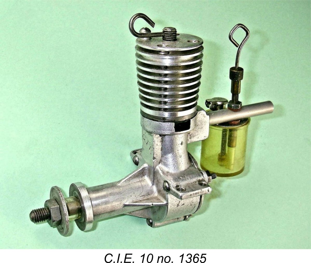
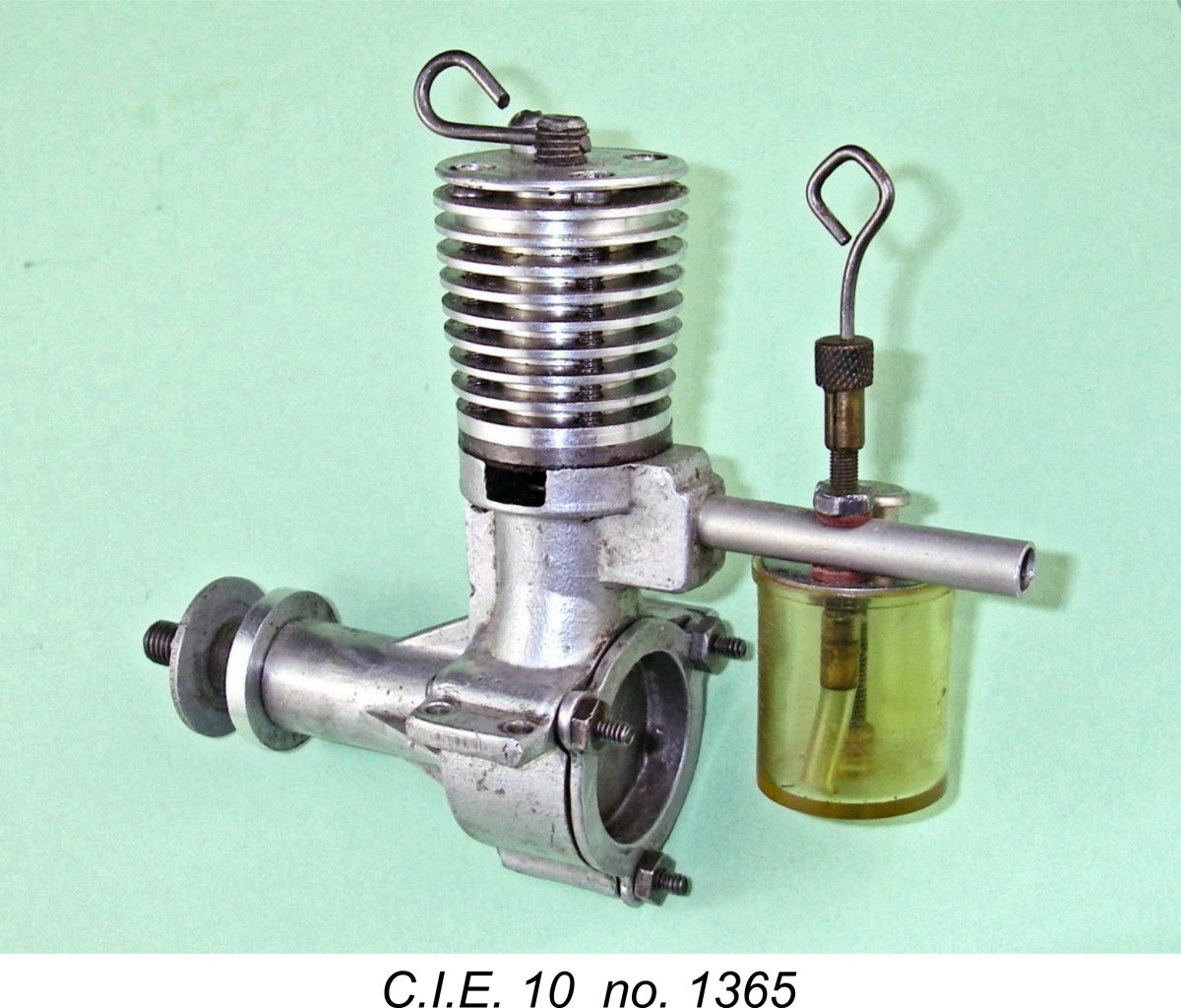
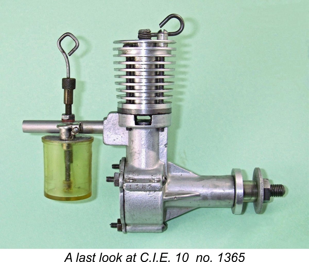
The tank was now omitted from many (but not all) examples, while a third variant of the compression lever made its appearance on some of the engines in this numbered series. This featured a loop at the outer end as opposed to the more usual straight lever. The needle control on some examples was also bent into a loop in the same manner. Previously illustrated engine number 1365 in my collection retains the tank and also features the revised controls. However, engine number 1362, which is only three units away from its 1365 companion, retains the earlier compression screw and also lacks a tank. It appears that the various components may have been mixed 'n matched at this (presumably) later stage. Owner intervention is also a possibility - there's no way of knowing.
One rather odd feature of some (but not all) of these numbered engines is the fact that an attempt seems to have been made to machine away the “CIE 10” identification on the front of the bypass - my own engine number 82 is a good example of this. There’s no question that the stamping was originally present - vestigial traces of it are quite unmistakable, as can be seen in the attached image. Moreover, one of Ron Chernich's original contacts regarding this engine stated that the stamping on his example too had been similarly obscured. Bert Streigler’s example also appears to have suffered the eradication treatment, so this does not appear to have been an uncommon step. Which leaves us with the question - why stamp the engines and then attempt to eradicate the stamping?!? The skimming of metal (on my example at least) was carried out quite neatly by turning in a jig, showing a high level of intent - the operator simply didn’t go deep enough to completely eradicate the former stamping. But after going to all that trouble, no attempt then appears to have been made to replace the former identification with a different stamping! Another of those aggravating little mysteries .............if only they could talk! The most probable explanation for this anomaly lies in the fact that at some point during the latter half of 1947 the production of these engines was transferred to a new manufacturer. We'll look at this change and its implications in the next section of this article. Enter HY-PRO
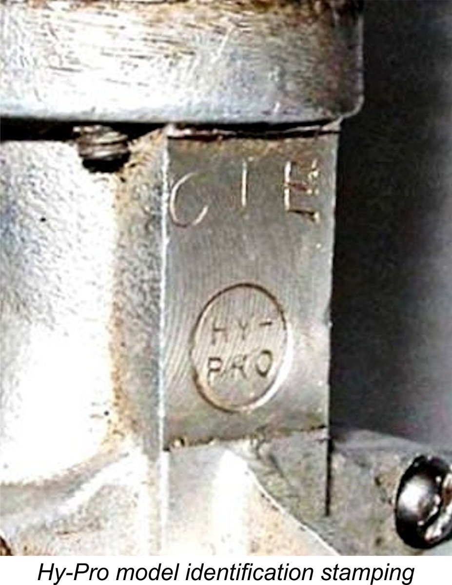
The engines themselves were now known as “CIE HY-PRO” units, many of them being clearly identified as such. The new manufacturer stamped this identification onto a flat area neatly milled into the front face of the bypass, as seen at the right. However, things were actually more complicated than that! At around the same time, a number of engines which had seemingly been made by the former manufacturers had their bypass areas "skimmed" to eradicate the former "CIE" or "CIE 10" markings. The bypass on my own engine number 82, which was described and illustrated previously, typifies this treatment. This "skimming" was accomplished in several different ways. Engine number 82 appears to have been set up in a jig to permit the bypass surface to be turned down. Although the former "CIE 10" marking was not completely eradicated, it's still a relatively neat job. By c One is immediately faced with three questions - why was this done; who did it; and why after all that trouble was the former marking not replaced with a different script? Any attempt to explain this seeming abberation must address all of these questions. One possibility is that when HY-PRO took over they "inherited" a number of complete unsold engines or unused components from the original manufacturers. These of course would have displayed the "CIE" or "CIE 10" markings described earlier, stamped onto the front face of the bypass. HY-PRO may have attempted to remove those markings by skimming metal off the front face of the bypass. However, this scenario fails completely to explain why they did not then re-mark the engines with the "CIE HY-PRO" inscription illustrated above. In fact, it fails to explain why they couldn't simply have added the "HY-PRO designation to the existing "CIE" inscription. A somewhat more convincing potential explanation that has occurred to me is that the original manufacturers may have retained some complete engines which were not part of the deal with HY-PRO. It's quite possible that HY-PRO merely wished to acquire the rights to the C.I.E. name and design along with the dies and tooling, hence being unwilling (or perhaps unable) to increase their investment by purchasing any existing unsold inventory. This would have left Modelcraft holding a certain number of unsold engines bearing the original markings. Since HY-PRO now presumably owned the "CIE" name, that name had to be removed from any residual examples which the original manufacturers wished to sell on their own account in an effort to recover the capital which they represented. Although extremely tenuous and completely unsubstantiated, this possible explanation does have the merit of explaining both the skimming of the bypass surfaces and the fact that they were not re-stamped. At this point, it appears to me to be the most likely explanation. I'm wide open to better suggestions!
According to Tim Dannel’s invaluable “American Model Engine Encyclopedia”, the HY-PRO car models were created using standard CIE HY-PRO cases from which the lugs were removed by grinding. This makes sense - dies are expensive things to make, rendering it highly unlikely that the manufacturers would have gone to the trouble and expense of creating a new one. However, if this was in fact the case it’s really quite impressive to note the lengths to which they went to re-finish the former lug location and restore an as-cast appearance. None of this was sufficient to permit the C.I.E. or its manufacturers to establish themselves in the market over the long haul. By early 1948 the glow-plug was beginning its rapid rise to complete domination of the American market, the result being that production of essentially all of the pioneering American diesels (including the CIE HY-PRO models,) had ceased by the end of 1948. The relative lack of availability of commercial diesel fuel in America may have contributed to this outcome. Diesel ignition was to make only one more spirited but relatively brief reappearance on the mainstream US manufacturing scene some years later in the form of the McCoy and OK diesels, At $18.50 the C.I.E. was fairly expensive by the standards of its day, being almost as costly as the larger and far more powerful Drone diesel. The one edge that it had over competing American designs like the Drone and Mite was the fact that it had variable compression, thus being able to accommodate a range of fuels and loads. But this alone was not enough to ensure its sales success. Barney Snyder’s recollection that Modelcraft sold “a few thousand” examples of the C.I.E. is certainly consistent both with recorded serial numbers and with the apparent number of present-day survivors. Following the HY-PRO takeover, a further thousand or so examples appear to have been marketed. However, this scarcely compares with the sales of over 15,000 units achieved by the Drone. By early 1948, production of the C.I.E. appears to have ceased, although it was included in the summary of model engines for 1948 which appeared in the January 1948 issue of “Model Airplane News”. This implies that it was still on the market in late 1947, when the article in question must have been written. An Aussie Variant of the C.I.E.
The Burford engines can easily be distinguished from the originals. The most obvious differences are nine cooling fins rather than ten; a translucent rather than transparent tank; a smaller-diameter prop driver; and a subtle little compression friction device comprising a socket head grub-screw that pushed a nylon pad against the brass compression screw thread at the rear of the engine. No written evidence exists, but we have it on good authority that Gordon, with typical irreverent Ozzie humor, called his engine the "CIA". David Owen, who ground the cylinders, believes that less than a dozen of these were made. Today, it’s probably far easier to find an original than one of Gordon’s beauties!! User Impressions As far as I’m aware, the C.I.E. was never the subject of a published test in any contemporary modelling periodical. However, it was mentioned in a number of articles relating to model diesels in general. As a preliminary to undertaking my own tests, I took a look at a few of the contemporary commentaries which were published in the US media during 1947. These were generally quite favorable. One of the more laudatory comments came from Jim Noonan in his article “The Development of Diesels” which appeared in the September 1947 issue of “Air Trails”. Noonan commented quite correctly that the C.I.E. was basically a European-style design which “never failed to start instantly”, but then went on to claim that it “packed more power” (than the European opposition) and developed “high rpm”. Feeling that these statements should be tested, I elected to run a comparison between the C.I.E. and one of its nearest British equivalents as of early to mid 1947 - the E.D. Mk. II of slightly lesser 2 cc (0.122 cuin.) displacement.
My initial impressions of the C.I.E. on test were extremely favorable, confirming Noonan’s comments in all respects. Once set correctly, the engine starts effortlessly on a few choked flicks, and the excellent control response ensures that optimum running settings are very easy to establish. Once that's done, the engine runs very smoothly indeed, swinging a relatively large prop with some authority. A perfect introductory diesel, in fact – just what one would think the US market would have needed in 1946/47 to sell the concept of diesel operation! Also very much in line with the claims made in the manufacturer’s instruction sheet.
On a “modern” diesel fuel, one has to increase compression a little from the running position to get a fast cold start and then back off as the engine warms up. This is typical behavior for a low-speed diesel of this type. Hot re-starts are very easy on running settings. Running is very smooth indeed once correctly set, and vibration levels are by no means excessive considering the very long stroke. All fits are superb – right up to the very best European standards, I’d say. The engine feels absolutely “silky”, with outstanding compression and no hint of tightness at any point in the stroke. The C.I.E. undoubtedly started every bit as well as Jim Noonan claimed - indeed, I would actually rate it an easier starter than the E.D. Mk. II on the basis of this comparative test. However, the claim to “high rpm” might legitimately be questioned - I suppose it comes down to one's definition of "high rpm"! Here are the figures that I obtained from engine number 82, along with the figures achieved on the same day with the same fuel and props using an unmodified November 1947 E.D. Mk. II (no. M1625/7) for direct comparison (in brackets):
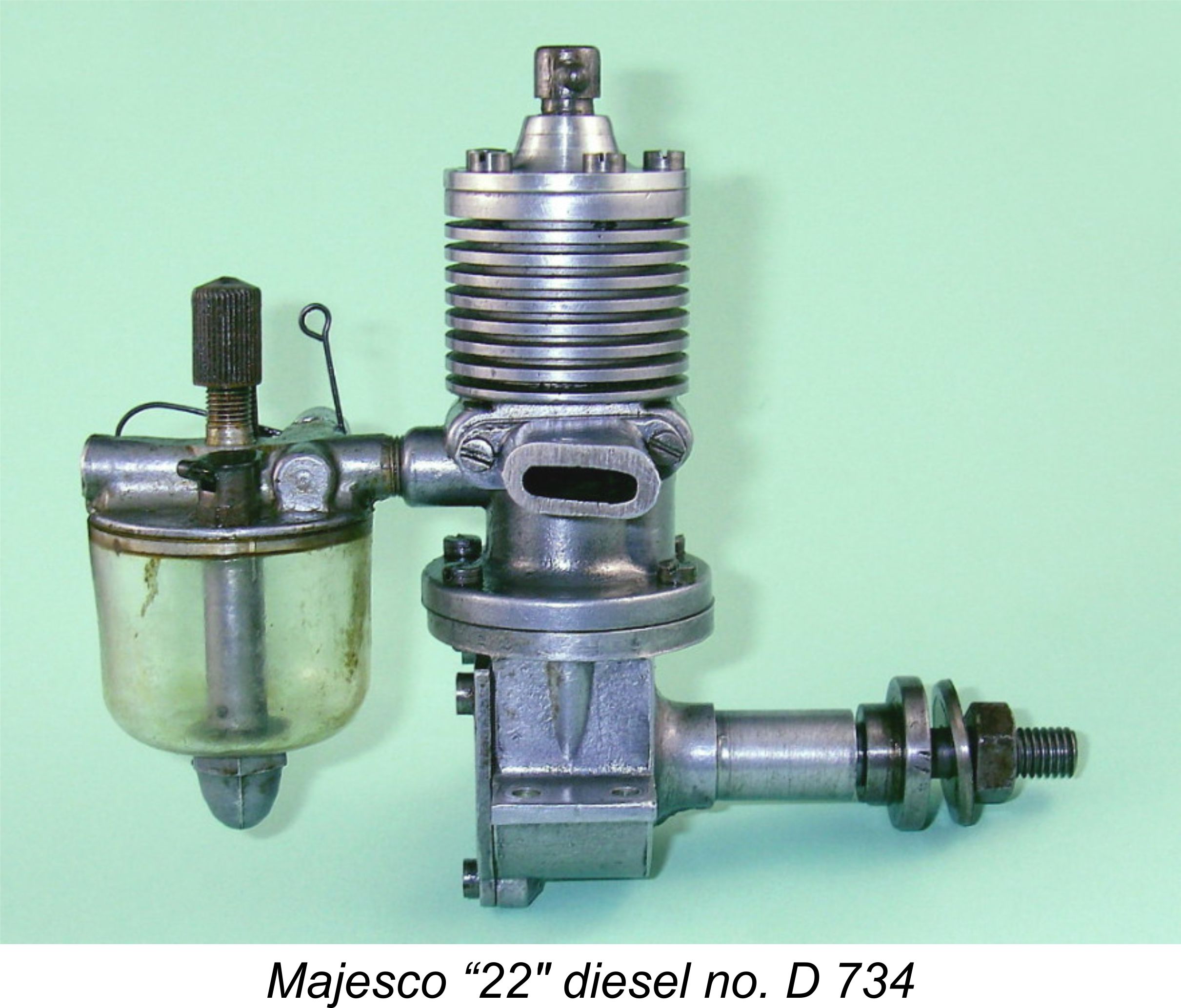
The BHP figures are those for C.I.E. engine number 82. Engine number 1352 produced almost identical figures despite the stickiness of the contra piston. As can be seen, the C.I.E. is only some 300-400 rpm up on the admittedly smaller E.D. Mk. II in the 6,000 - 7,000 rpm bracket but pulls away to a commanding lead above 7,000 rpm. It’s apparent from the above figures that the Mk. II is more or less done by around 6,700 rpm, while the C.I.E. continues to improve well into the 7,000 rpm bracket. On this basis, Noonan’s claim to "more power" appears reasonably well justified, although we have to remain ever mindful of the Mk. II’s displacement disadvantage. The mere 900 rpm gap between the 8x6 and the far “faster” 8x4 for the C.I.E. shows that it’s clearly pretty much topped out by about 8,000 rpm - not much of a surprise there really given the inherent limitations of the long-stroke sideport design. We might tend to scoff at Jim Noonan’s claim to “high rpm” on this basis, but in fact a peaking speed in the 8,000 rpm neighborhood was pretty good by early 1947 standards, especially for a long-stroke sideport engine. Context is everything ............... The power output figures in the above table are derived from calibration factors derived over a long series of tests on various engines using the props in question. The numbers imply a well-defined peak of around 0.107 BHP at somewhere in the region of 7,800 rpm. Nothing spectacular for an engine of this displacement, but a useful enough performance for practical purposes by 1947 standards. The manufacturers of the C.I.E. clearly recognized the engine’s speed limitations - their recommended props in the 9x6 to 10x4 range all turn in the low 7,000 rpm range on the bench, thus appearing well suited to the engine’s Since the original drafting of this article and the associated testing, I did acquire a nice example of the Majesco "22" of only slightly lesser 2.2 cc (0.134 cuin.) displacement. This would have made a fairer comparison, since it is a direct contemporary of the C.I.E., also having a closer displacement than the E.D. Mk. II. A test on that engine conducted for my companion article on the Majesco range yielded an output of 0.098 BHP @ 6,000 rpm. Unfortunately I used a different series of calibrated props for the Majesco test, hence being unable to report any directly comparable prop-rpm figures at the present time. The only comment that may be made is that the specific outputs of the Majesco and C.I.E. (BHP/cc) are almost identical. The Majesco develops its peak power at a significantly lower speed, evidently producing considerably more low-end torque and hence being able to handle slightly larger props. However, in practical terms the field performances of the two engines would have been very similar. Conclusion
It must be said that this engine was a really fine effort on the part of Barney Snyder and his associates, certainly meriting more success than it achieved. It would have made a really user-friendly engine for sport flying. If it had been made available on the European market it would likely have found many buyers, since it was a better-than-average starter that was well up to the best then-prevailing European standards of quality, handling and performance. On that 10x4 prop it shifts a fair amount of air and would pull a decent-sized free flight model aloft for sure. A small C/L model would probably do OK on the 9x7, allowing for airborne pickup. Too bad the engine didn’t catch on.................it richly deserved to do so!! ______________________________ Article © Adrian C. Duncan, Coquitlam, British Columbia, Canada First published October 2015
|
||
 This time we return to the USA for a look at one of the better American efforts in the field of model diesel engine manufacture. Our subject is the C.I.E. 10 diesel, which was a very neat and extremely well-made 2.41 cc (0.147 cu. in.) sideport unit produced in modest numbers by two successive manufacturers in Los Angeles, California from late 1946 through to early or mid 1948.
 arts. Dependability was another factor - once a diesel was started it would keep running as long as the fuel supply held out, because there was basically nothing to go wrong provided the mechanical structure stayed together!
  Foremost among the American diesels was Leon Shulman's famous 0.297 cuin. (4.85 cc)
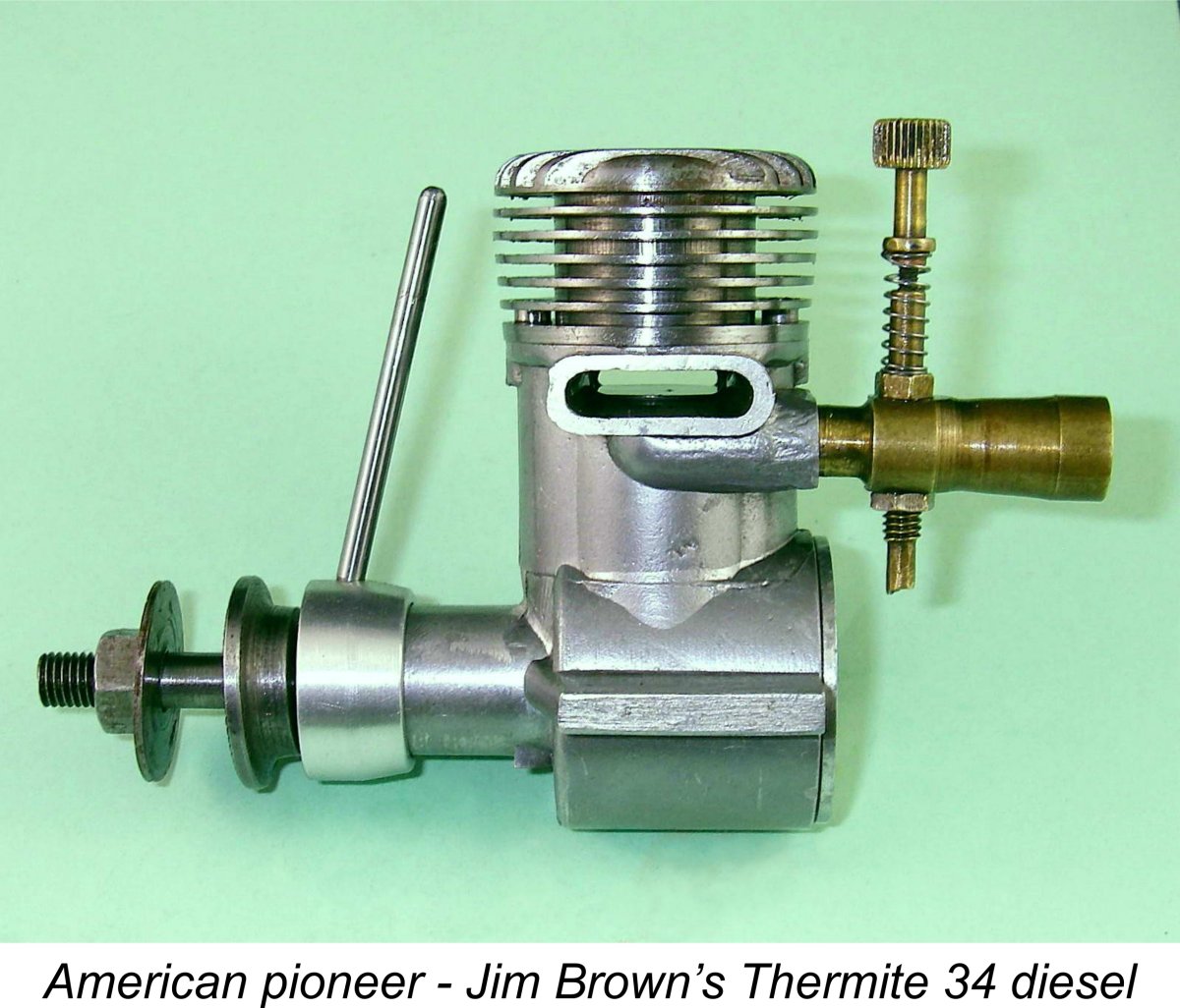
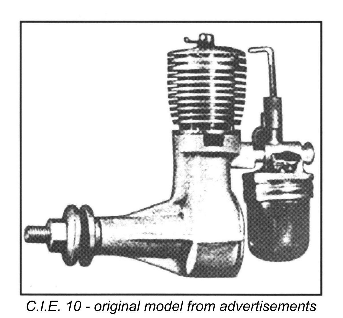 The initial version of the engine seemingly had a hang-tank beneath the venturi intake which screwed into a metal cap beneath the intake. A Gits filler cap was employed on this tank. This tank assembly closely resembled that used on the contemporary Brownie 29 spark-ignition unit, to the point that it may in fact have been “borrowed” directly from that model.
  The version which undoubtedly did appear on the market in commercial numbers in late 1946 (about the same time as England’s first commercial diesels, the
 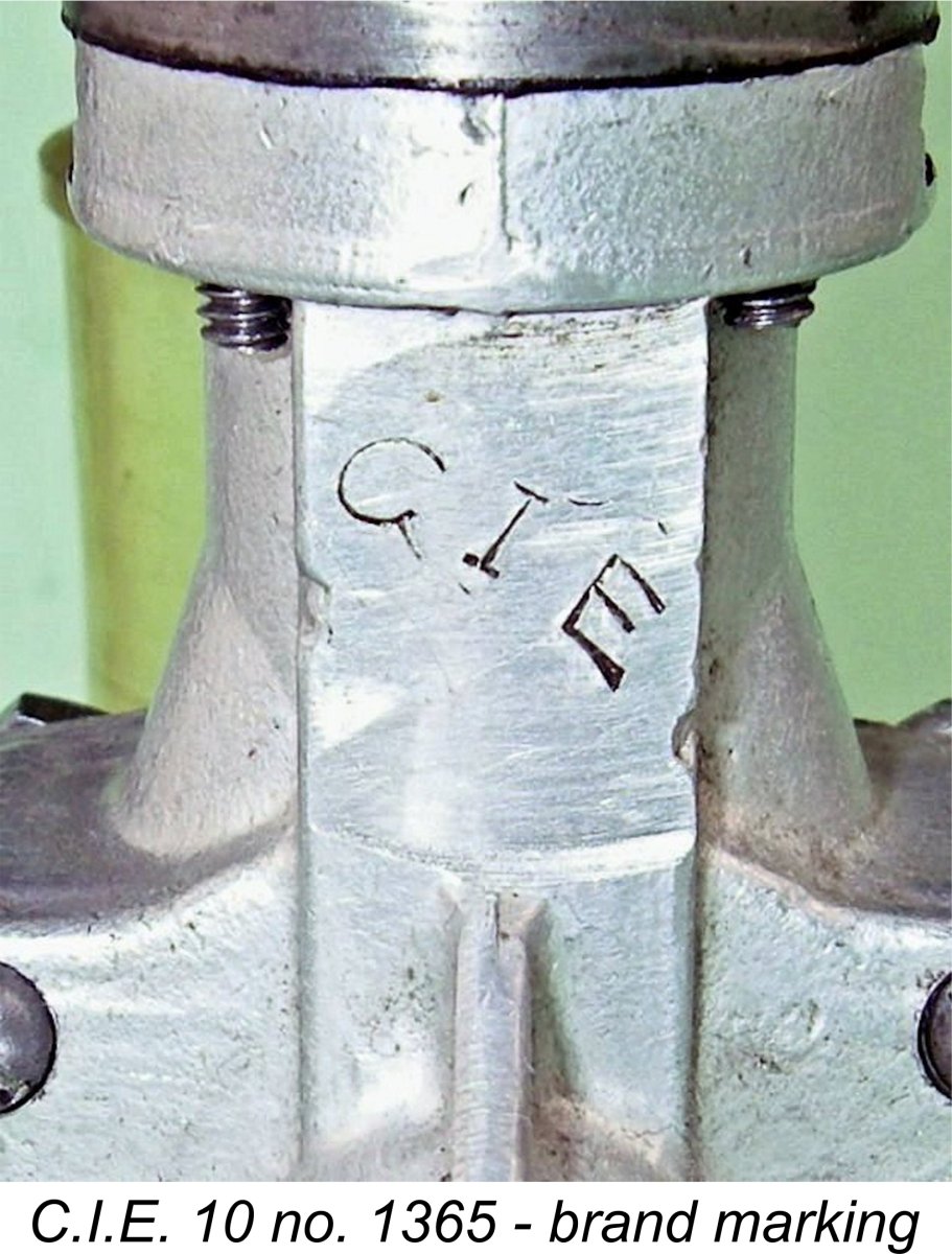 ont of the bypass. One must ask why this machining of the bypass was carried out at all, given the fact that it would have been easy to stamp the as-cast surface or even cast the letters onto the surface directly. One theory is that the machining was intended to make the marking stand out. However, a cast-on marking would have stood out just as well, making this appear to be a rather thin explanation. Perhaps a more plausible possibility is that this area was where the casting sprue was located, hence requiring some form of dressing.
 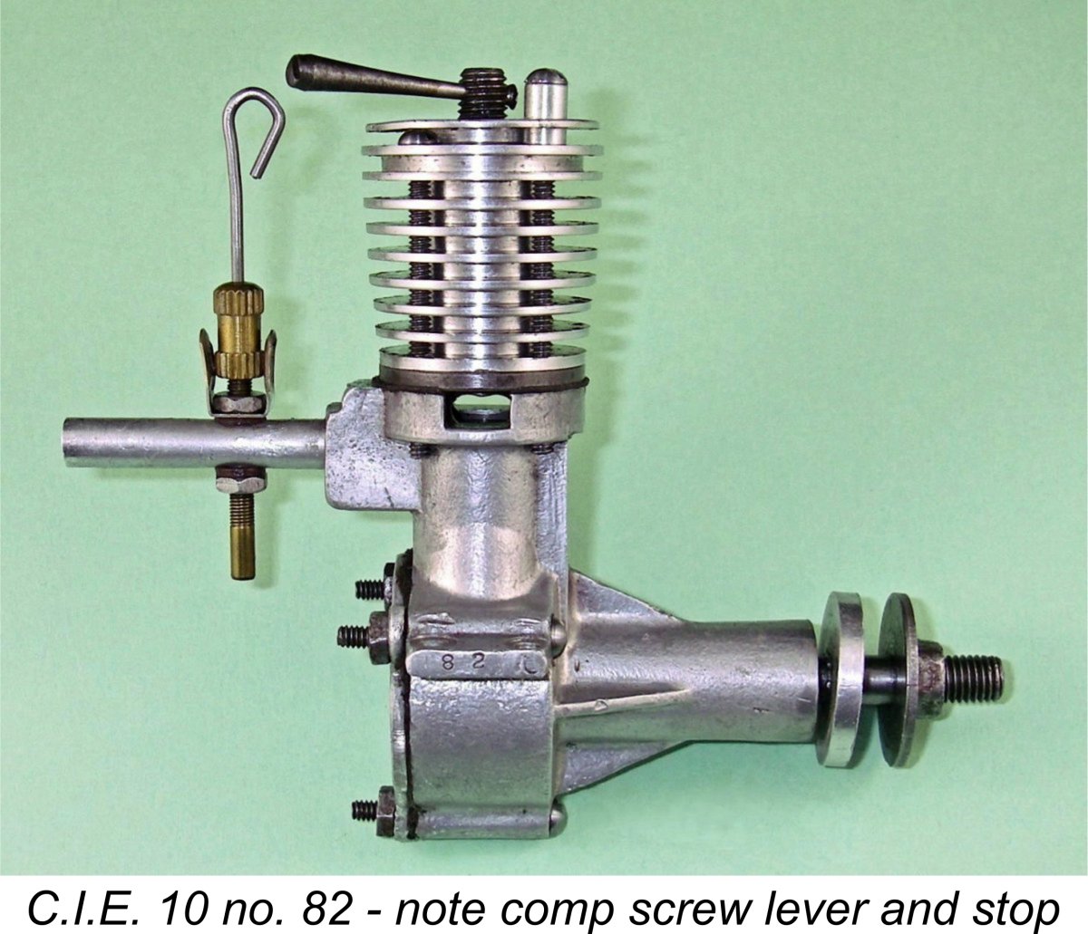 The compression screw lever design varied somewhat - some were merely a straight piece of wire, while others were nicely machined into an elegant taper widening towards the control end like a miniature baseball bat. The thread used for the compression screw was a very practical ¼-28.
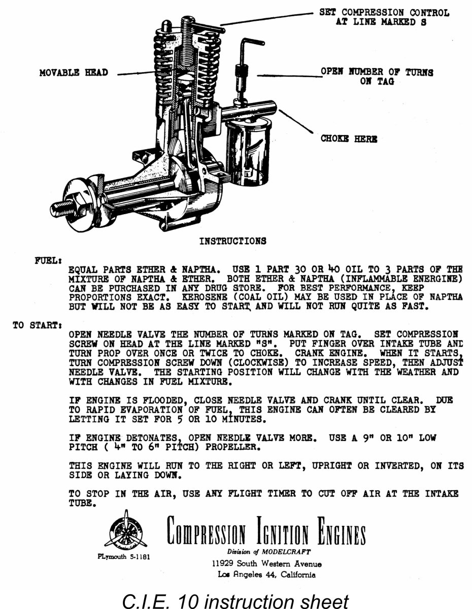 ll stamped letter S with a radial line inscribed on the top of the alloy cooling jacket, indicating the starting compression setting. Reference is made to this mark in the instruction sheet, which noted correctly that the setting was in fact dependent upon factors such as atmospheric conditions and the fuel used. This being the case, the indicated setting was very much a guideline, or a “starting point” if you’ll pardon the pun! As presently configured, the mark is about right on my examples for cold starting on a low-nitrate fuel – as with most low-speed engines on nitrated fuel, you have to back off compression as the motor warms up. Engines of this type actually tend to run better on un-nitrated fuel.
 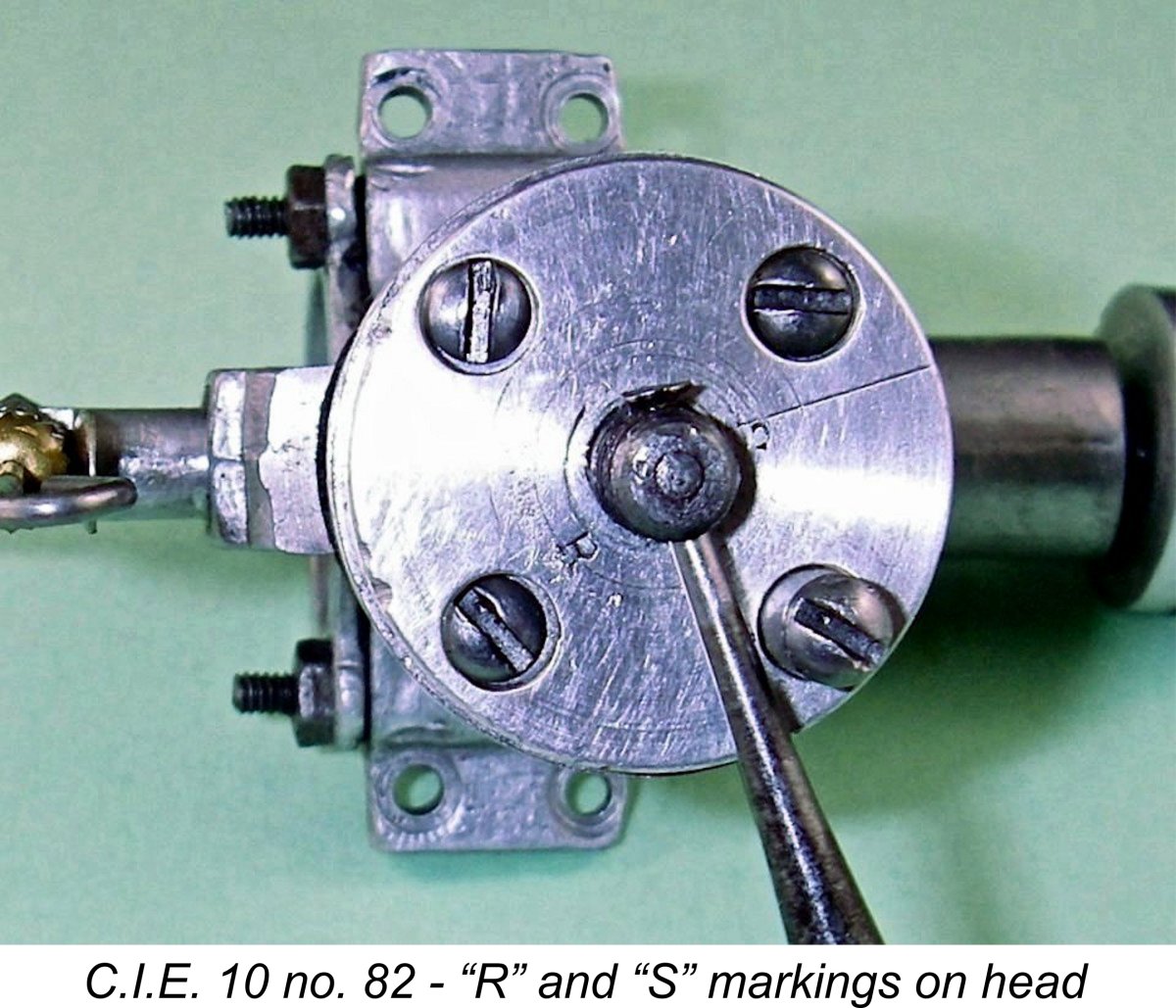 brought. This could be done after the best starting setting was established on the bench. The instruction sheet hinted at this approach by describing the cooling jacket as “moveable”. Overall, the makers appear to have clearly recognized the unfamiliarity of diesel operation to most US modellers in 1946, hence going out of their way to make this engine as foolproof as possible in terms of starting. Once the settings were established, there was no danger of losing them, while the engine was as well protected as possible against hydraulic locks.
 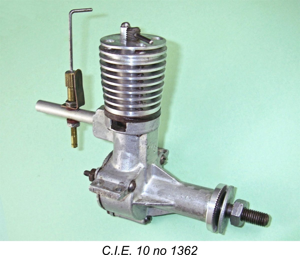 The earliest engines apparently did not bear serial numbers. However, that changed during the first half of 1947, when the engine was slightly revised once more. At around that time the engines began to display serial numbers which were neatly stamped onto the outer ends of the right-hand beam mounting lugs (looking forward in the direction of flight). The fact that I own previously-illustrated engine number 82 appears to confirm that the numbering sequence started at engine number 1.
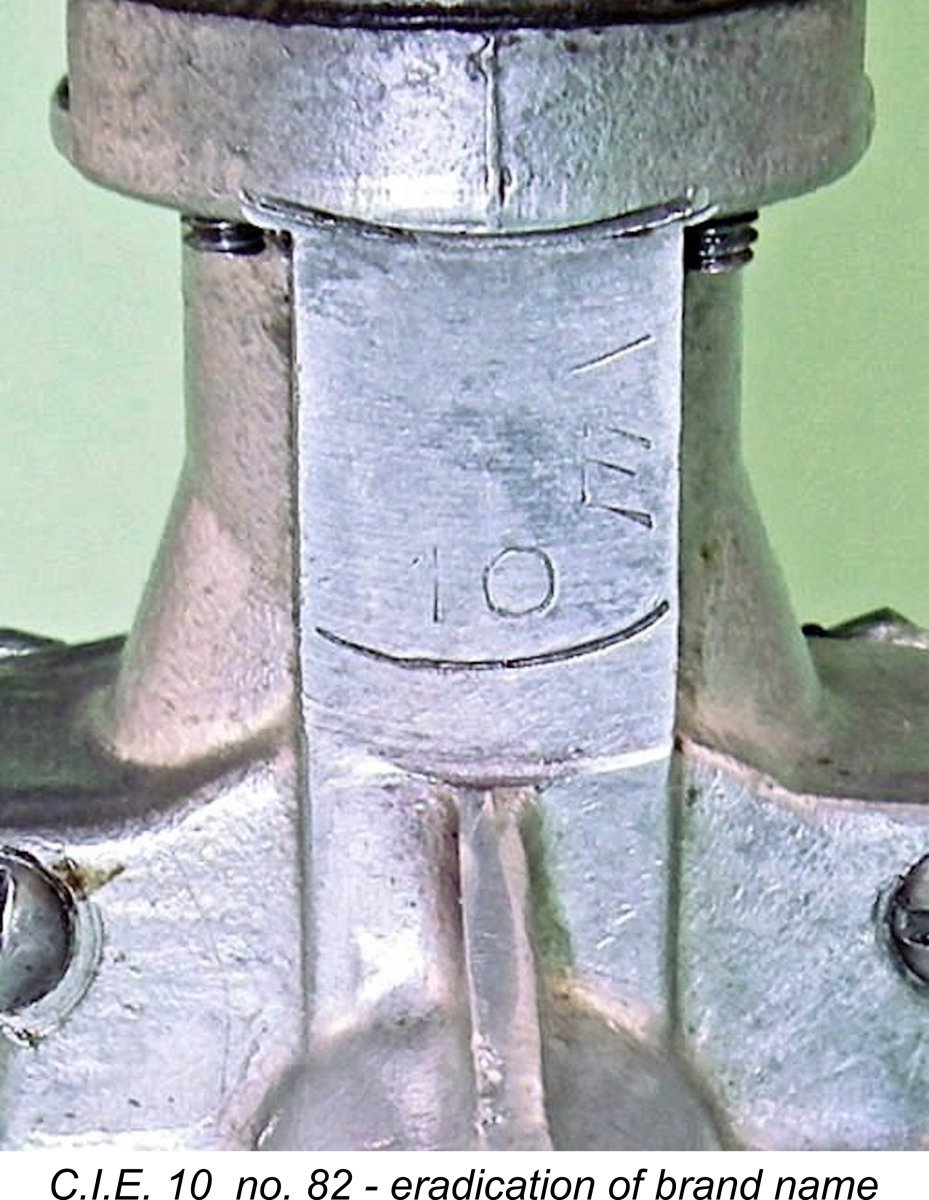
 Later in 1947, there was a change in the manufacturing arrangements for the engine - a new name entered the picture in the form of HY-PRO Engines, also of California. The design of the engine remained essentially unchanged, but there were a number of variations in the manner in which the engines were machined and identified. This change seems to have come after at least 1365 numbered examples of the engine (and quite possibly more) had been produced by the original manufacturers.
 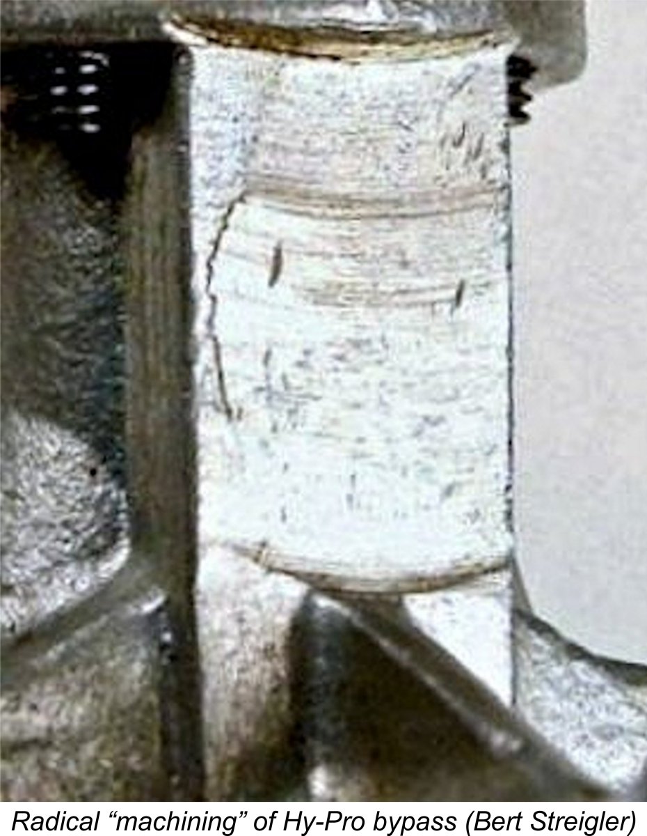 ontrast, the front face of the bypass on the example in the late Bert Streigler's collection illustrated at the left looks as if it's been introduced briefly to a grinder fitted with a cup wheel!
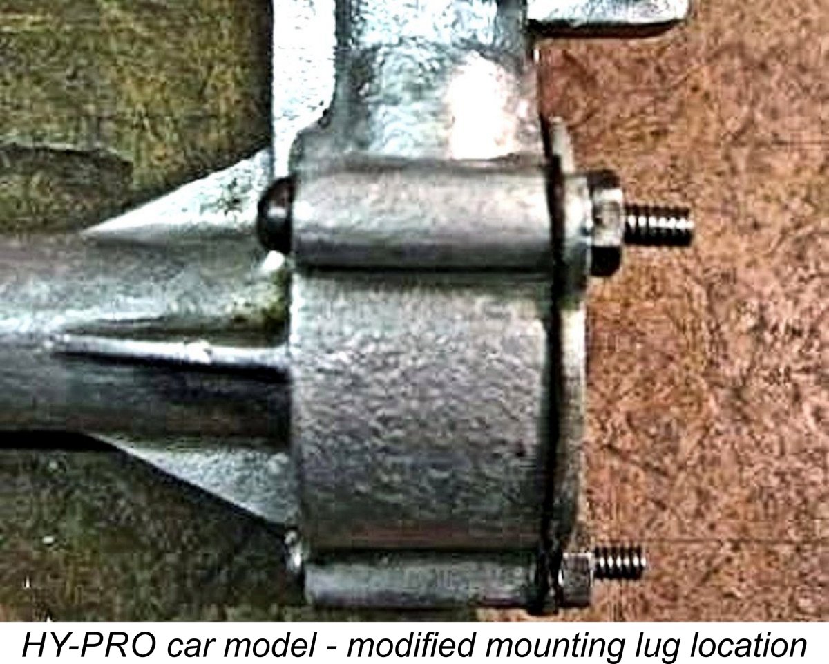
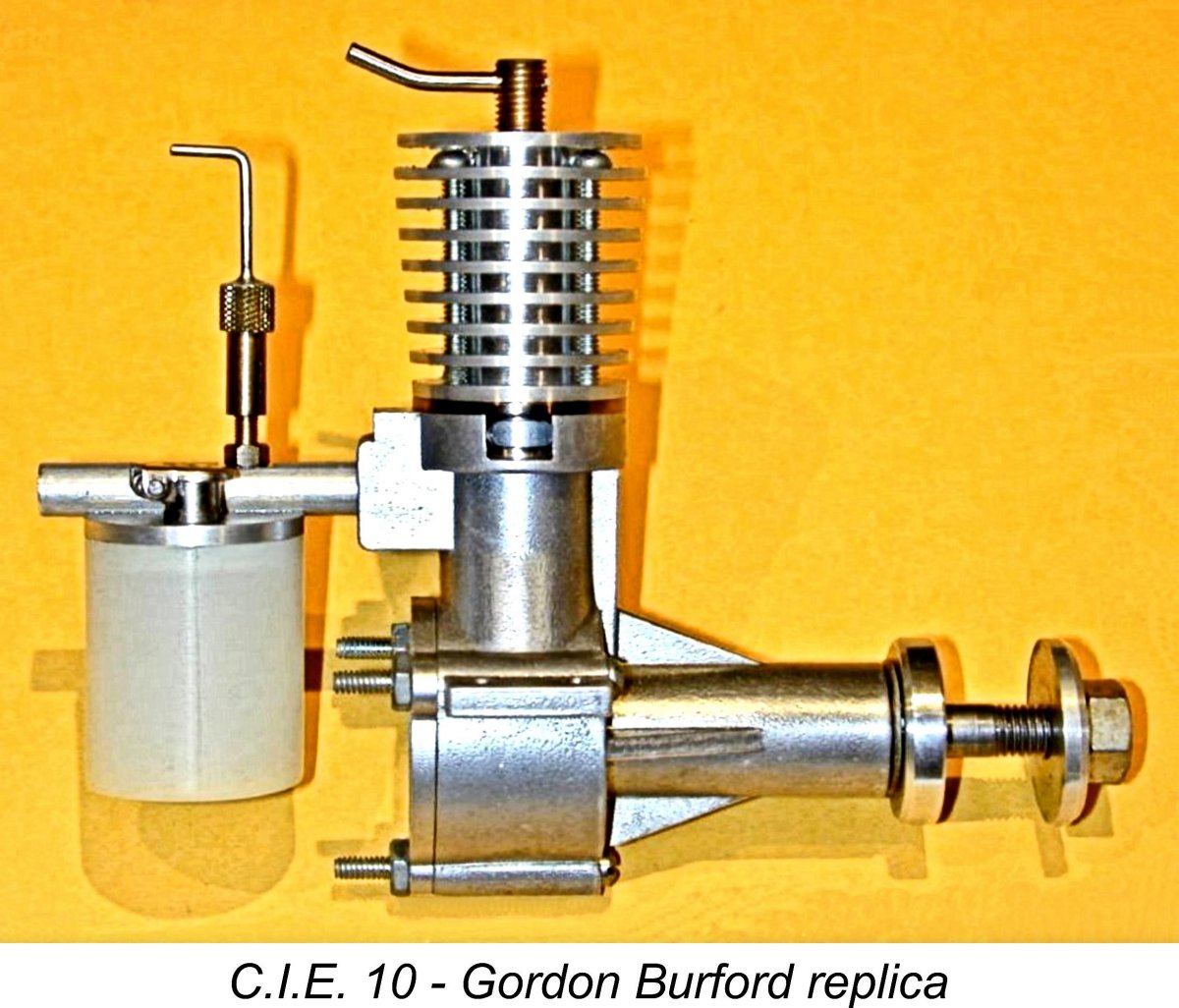 Outwardly, the C.I.E. "10" is a very conventional example of the long-stroke side-port diesel which dominated the diesel market in early post-war Europe and has enjoyed a renaissance in recent years due to the burgeoning interest in engine collecting and vintage flying. This naturally made it a logical target for latter-day replication. In the mid-1990's, it reappeared for a short time as a small-scale reproduction "collectable" by Mr. Taipan, the late and much-missed Gordon Burford.
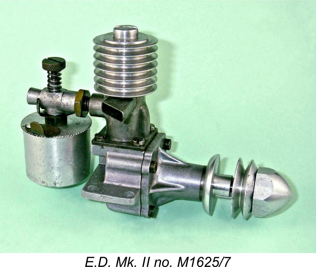 The comparison is perhaps not quite fair since the E.D. is giving away some 18% in terms of displacement. I was aware that a fairer comparison would perhaps be with the slightly larger
 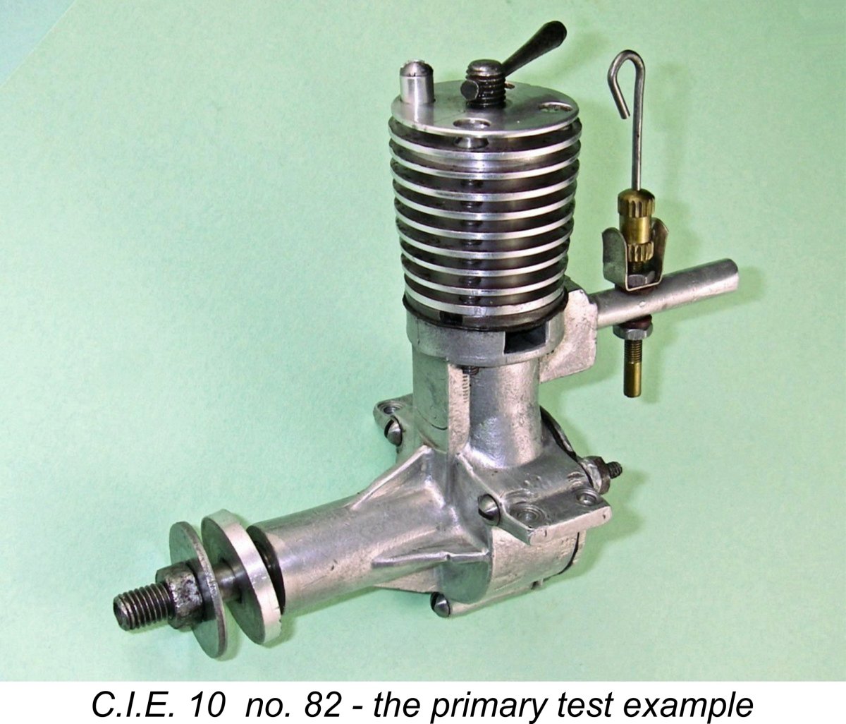 The contra-piston on one of my tested examples (no. 1362) proved to be a little tight, especially given the fact that this component is made of steel - contra-pistons of this material have a well-documented tendency to stick in a hot bore. However, this stickiness would work itself out with a bit of running – the example in question appears little used. The other tested example (no. 82) has had quite a bit more use and seems perfectly fitted. It is readily adjustable at all times while holding its settings firmly. It proved to be if anything a little faster than engine number 1362, likely due to the greater ease of securing precise compression adjustments. I therefore focused on that example for this test.
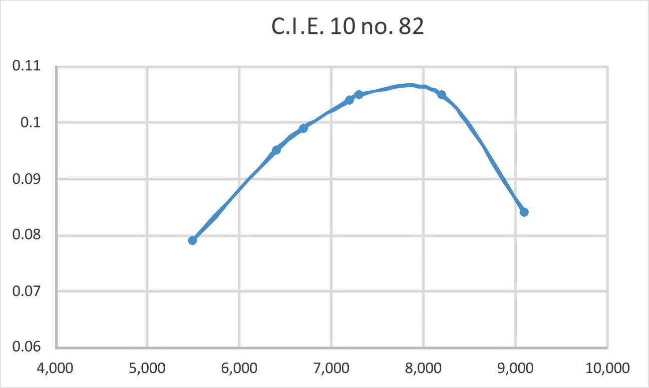
 The C.I.E. is a most desirable acquisition for collectors of American diesels but is becoming increasingly hard to obtain in new or near-new condition. As of the time of writing in 2015 the original $18.50 price had ballooned to over two hundred for a nice one, reflecting the high value of relatively rare diesels in general. But the little gem is a beauty - well worth tracking down! Enough of them were made that they haven’t yet quite entered the “unobtanium” realm. Grab one before they do ....................
| |