
|
|
The MD-5 Kometa – Was it Really THAT Bad??
Introduction During the mid to late 1950’s, the Italian Super Tigre engines designed by Jaures Garofali and made in Bologna, Italy by Micromeccanica Saturno were doing extremely well in the international contest sphere. The only engines that consistently offered any serious challenge to the factory-prepared Super Tigres used by the leading Italian fliers during this period were the tool-room “specials” produced in very small quantities by state-sponsored institutions such as MVVS in Czechoslovakia (now split between the Czech Republic and Slovakia) and (later) MOKI in Hungary. I've covered the MVVS story in detail in a separate article which may still be accessed on Ron Chernich’s “Model Engine News” (MEN) web-site, while the MOKI story has been recounted in a separate article on this website.
To many in the present day and age, the fact that the Communist regimes of the 1950’s saw model airplane competition as an important vehicle for furthering their political agenda may appear a bit surprising. It’s a question of context - to understand this perspective, we have to mentally transport ourselves back two-thirds of a century to the 1950’s. At that time, aeromodelling was a far more mainstream hobby than it is today, with a very much higher proportion of younger and hence perhaps more impressionable participants. There were a variety of reasons for this, including the absence of today's competing cyber-activities as well as the fact that the later rise to prominence of R/C, which created an economic barrier to participation by young people, had yet to gain momentum. Be that as it may, the widespread participation in aeromodelling meant that the major modelling magazines were widely and avidly read by a broad age group, with international contest results being reported and analysed in detail. Iron Curtain successes on the International aeromodelling stage thus reached the consciousness of a far broader audience than would be the case today, thereby furthering the political agendas of the countries involved.
The result of this situation was that, unlike their Iron Curtain competition, Garofali and his colleagues were more than happy to sell off-the-shelf examples of their latest competition engines to anyone who had the money! Moreover, there were other competing manufacturers who were equally willing. Consequently, modellers in Western countries could readily obtain high-quality production versions of up-to-date competition motors which could then be tweaked by their more knowledgeable owners to yield something approaching the performance of the factory-prepared units which were always at or near the top of the results sheet in any International contest.
This posed a problem for the Communist authorities concerned with the elevation of their countries’ status and the promotion of their ideology through the well-publicised achievement of success in all forms of sport at the International level. The development of the talent pool from which International-standard power model competitors could be drawn was severely limited by the fact that suitable engines simply weren’t available in the quantities required to allow a sufficiently large group of would-be participants to gain the essential practical experience in their chosen activity.
It was anticipated (with some justification) that this approach would greatly increase the talent pool from which future International competitors could be selected. This in turn would lead almost inevitably to a sharp rise in performance standards.
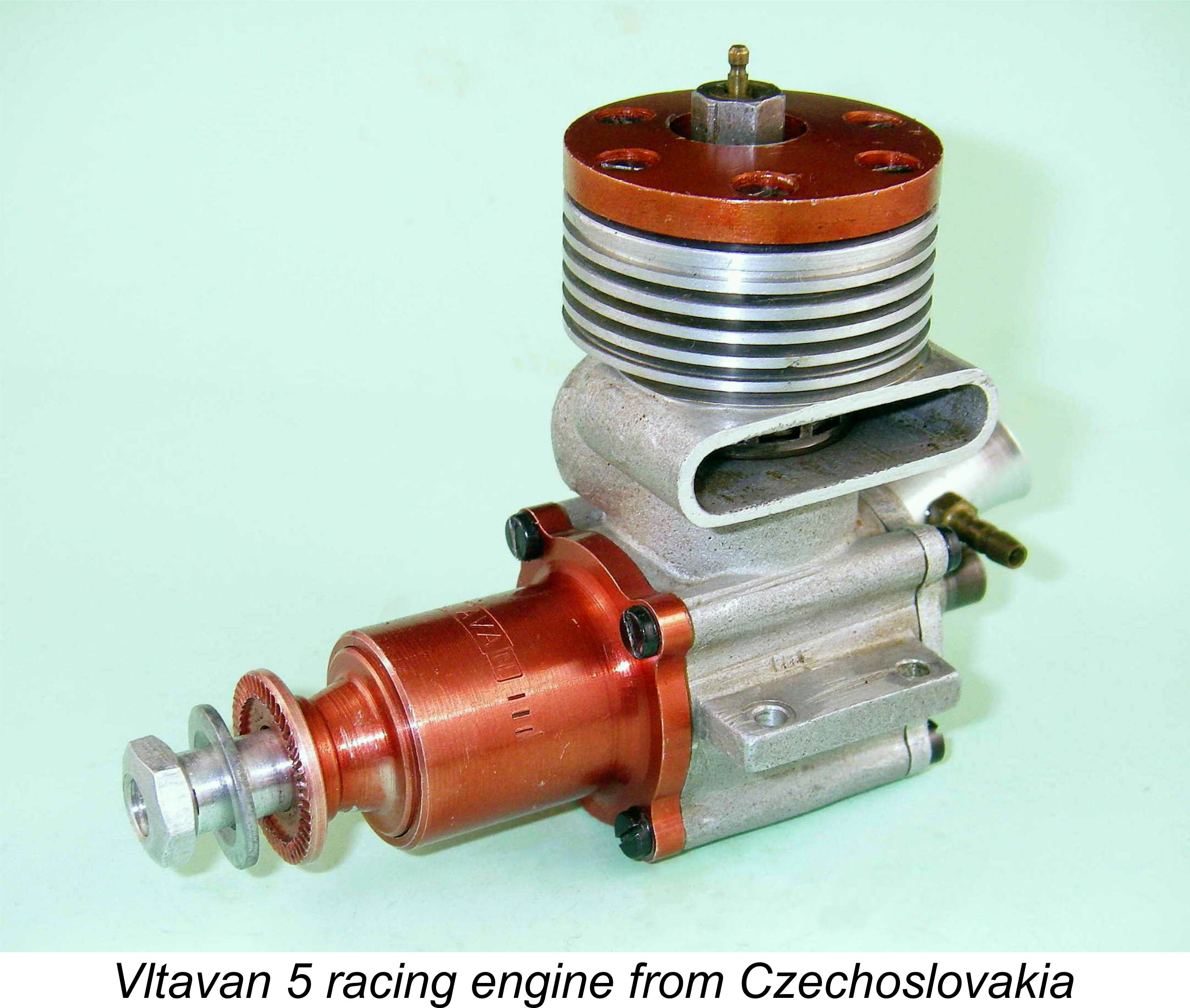
After 1959 the Czechs abandoned the Vltavan models in favour of increased production levels at the MVVS workshops, thus taking the first step towards the transmutation of MVVS from a state-sponsored “prestige” operation to the commercial enterprise that it was soon to become. A test of the commercially-produced MVVS 2.5R-58 may also be found elsewhere on this website. Let’s look now at the parallel moves made by the neighbouring Russians to achieve the same ends. The Russian Initiative As of the mid 1950’s, the Russians had made little impact on the International modelling scene, although they were increasingly putting in appearances at major competitions for the dual purposes of gaining practical experience and sizing up the opposition. Reliable information regarding model engine development activities behind the Iron Curtain remained extremely hard to come by at the time in question since the Cold War was in full swing and the “official” release of all such information was carefully managed by the State. In addition, Russian competitors in the international arena were kept on a very tight leash by the team officials appointed by their government. However, face-to-face contact between Russian modellers and their Western counterparts did inevitably occur on the flying field from time to time. Since the camaraderie between modellers the world over was of course unaffected by political divisions, some relatively uncensored information leaked out by that route. Through the same process, the odd Russian engine found its way “under the table” into the hands of a few Western modellers.............. and doubtless vice versa! It was apparent from such contacts that the Russians had already begun the process of developing their own original engine designs. Peter Chinn wrote a pioneering article entitled “Russia’s Engines” which appeared in the September 1953 issue of “Model Airplane News”, but the engines covered in that article Chinn commented in the article that Russian engine designers at this time appeared to be at least five years behind their Western counterparts, although he did find evidence of some original thinking in several of the designs listed. In making these statements, Chinn was being a little unfair to Russian model engine designers because they were designing to very different criteria from their Western counterparts. Russian model competitions during the early post-WW2 era were very much focused on the establishment of records for free flight speed, dustance, duration and altitude as opposed to the more familiar "climb 'n glide" contests based on a limited motor run. Dependable operation over extended periods with low fuel consumption were therefore the major design objectives as opposed to all-out performance. In fact, unknown to Chinn, things had already turned the corner as the Russians began to look towards participation in International contests during the early 1950's. In the “Motor Mart” feature published in the August 1955 issue of “Aeromodeller” magazine, mention was made of a 100 page book published in Moscow in 1954 in which all aspects of the design and construction of model engines were covered in varying degrees of detail. At least in part, the goal of the book was clearly to assist those who were interested in designing and building their own engines, thus stimulating model engine development in the country. Detailed instructions for building the CAML-50 side-port diesel of 1.8 cc displacement were included, together with details and illustrations of a number of then-current Russian engines. An English translation of this book will be found elsewhere on this website. The illustrated engines included the 1952 MB-09 2.5 cc racing glow-plug engine which is shown below. Designed by a well-known Russian free flight modeller named Vladimir I. Petukhov, this was a considerable advance over typical home-grown Russian competition efforts of the early post-WW2 record-seeking era. It sported such up-to-date features as a ball bearing crankshaft, rear disc valve induction, a non-metallic disc, a lightweight lapped cast iron piston and a remote single-nozzle needle valve set-up, but still retained a somewhat “old fashioned” look in other ways and certainly never achieved any International success, although it did reportedly establish several Russian speed records, including a quite creditable control-line mark of 183 km/hr in 1956. That speed would have been good enough to win the previous year's World Control Line Speed Championship! The MB-09 is covered more completely in my companion article on Soviet model engine development. It was subsequently developed into the better-known VIP-20 glow-plug motor of the late 1950's.
The obvious catch-up solution was very simple – look around for an established and successful competition design from elsewhere and then simply copy it! The resulting engines would at least have been made behind the Iron Curtain, even if they weren’t designed there – in prestige terms, half a loaf is far better than none! At the very least, they would gain valuable manufacturing experience. And while aspiring Russian competitors used the resulting engines to gain experience in their chosen events, the Russians’ own engine development program could quietly continue. When their own engines were ready, they could be brought out to replace the clones - their users would be ready! A perfectly logical approach if it could be made to work. Subsequent research has demonstrated that the cloning concept was by no means new - the pioneering Russian AMM-1 and PP-4 models of the 1930's had been clones of the Brown Junior and Baby Cyclone designs respectively. Moreover, the widely-used 1.8 cc CAML-50 sideport diesel of 1950 was a faithful copy of the Czech Atom diesel of the same displacement. Full details are set out in my companion article on the history of Russian model engine manufacturing to be found elsewhere on this website. This was the approach that was revived by the Russian sporting authorities at some point in the mid 1950’s, probably more or less concurrently with the Czech move to establish the Vltavan “consumer grade” engine line. The only question for the Russians was – what to copy!
Established competition motors such as the Webra Mach 1 diesel and the various Super Tigre glow-plug engines would have immediately presented themselves as potential prototypes – they were in such widespread competition use during the mid 1950's that getting hold of an example at some International meet would not be too hard. Furthermore, since these motors were produced in Germany or Italy and the copies would be made in Russia, the entire weight of the Iron Curtain lay between them, allowing the Russians to snap their fingers at any moves by the original designers and manufacturers to take legal action against them – they were effectively immune from any such challenges! So this is exactly what the Russians did. They began to collect data on a number of competition engines from beyond the Iron Curtain, including several Super Tigre products. They then arranged for the series production of what amounted to replicas of some of these engines at an established Moscow factory which had previously been mainly concerned with defence production and sport aircraft maintenance.
An early subject of the Russians’ attentions was the 1954 version of the Super Tigre G21/29 racing glow-plug engine of 5 cc displacement. At the time when this motor was developed by Super Tigre, the control-line speed World Championships were still being contested in the 5 cc class, making that category a very important one in competition terms. The G21/29 was a top performer by the standards of its day, making it a logical choice for the Russians to copy. The model which resulted from this cloning exercise was designated by the Russians as the MD-5 Kometa (the latter being Russian for “Comet”). It is this model which is the main subject of the present article. The same Moscow factory went on to produce other such copies, including clones of the Webra Mach 1, MVVS 2.5R-58 (the MD-2.5 Moscow) and the Super Tigre G20/15 glow-plug and diesel models which were respectively identified as the MD-2.5 Meteor glow and diesel. Other factories manufactured original diesel models such as the well-known MK-17 and KMD 2.5 models which achieved some sales success in Western markets. The latter engines were intended all along for export, hence being very well finished. Here we will focus on the Kometa, since it was that model which first brought the Russian cloning initiative to the attention of Western modellers. The Prototype
Be that as it may, the 5 cc Super Tigre seems to have been the first competition glow-plug engine from outside Russia to receive the cloning treatment at the hands of the Russians. The 2.5 cc class did receive later attention, with Russian-made clones of both Super Tigre and MVVS prototypes being produced. But that’s another story ………….. The Super Tigre G21/29 was one of several Garofali-developed glow-plug motors of basically similar design, each of which was designated as a G21 model followed by the displacement in cubic inches. The 5 cc version had been developed primarily for control line speed and Open class free flight work. For the most part it was a fairly conventional contest glow-plug motor of its day. Its main departure from the established “racing engine” layout was its use of an extremely well-developed crankshaft front rotary valve (FRV) induction arrangement in place of the “classic” disc rear rotary valve (RRV) set-up. Super Tigre was the first major manufacturer to consistently succeed at the International level with FRV engines in all-out speed competition. Indeed, they were to remain steadfast in their adherence to the FRV arrangement for many years. At the time when the G21/29 emerged, they were still apparently hedging their bets to a degree, since the main casting for that engine incorporated lugs at the rear of the case which could have been used to attach a removable backplate complete with disc valve set-up. The backplate was cast integral with the rest of the crankcase, but the option to convert to RRV operation by machining away the integral backplate was quite intentionally retained. The Russians copied this feature exactly when producing the Kometa, although they never produced a disc valve version as far as is known. Other than the method of induction, the 1954 version of the G21/29 adhered to mid-1950’s racing engine convention by using cross-flow loop scavenging in combination with a lightweight ringed aluminium baffle piston, a well-developed transfer system and a crankshaft carried on two ball bearings. The engine was considerably over-square, having bore and stroke measurements of 19 mm and 17 mm respectively for a displacement of 4.82 cc (0.294 cuin.), thus complying with American Class B rules. The piston crown was heavily contoured into a McCoy-influenced domed baffle configuration, with the cylinder head being internally shaped to conform to this arrangement. The plug was offset towards the transfer side, again following the lead of McCoy and others. The resulting engine was a fine performer which did very well indeed in its class on the contest field. The Italians claimed an impressive output (by 1954 standards) of 0.80 BHP at 17,500 rpm on 30% nitromethane, but this claim appears to have been a trifle exaggerated since Peter Chinn and other competent testers were unable to duplicate these figures with over-the-counter examples. Even so, the engine was an extremely strong runner by then-current standards. If the Russians could make a reasonable copy of this model, they would have a very sturdy performer on their hands! The Kometa Appears
The name of the engine is rendered as MД-5П Kometa in the Russian alphabet. The usual English pronunciation of the first two symbols as MD is phonetically correct. The final figure П which appears on boxes and in factory documents relating to the engine is phonetically rendered as “P”. The significance of this letter is unclear, and it is generally omitted when discussing the Kometa. The engine has been designated as the MD-5 Kometa from the outset in the various English-language publications in which it has appeared. I will adhere to this convention. Following Chinn’s announcement regarding the MD-5 Kometa, examples were subsequently seen in action at the 1958 Control Line World Championships in Brussels, where they were used by the members of the first-ever Russian international stunt team to place 9th, 10th and 13th for a highly respectable 5th place finish in the team standings. This was a very impressive performance for a group of first-time entrants using what was at heart a control line speed engine! At least one additional example found its way to England as a result of this point of contact, subsequently being featured as the subject of a test by Ron Warring which was published in the November 1958 issue of “Aeromodeller” magazine. More of this test below ………. By November 1960 Peter Chinn was able to report in that month’s “Latest Engine News” column that at least three more examples of the Kometa had found their way to England. According to Chinn, opinions of the engine varied widely – one owner characterized the engine as “very good”, another as “mediocre” and the third as “useless”!! After such a range of endorsements, it would appear that nothing that anyone could subsequently say about the engine would come as much of a surprise………..
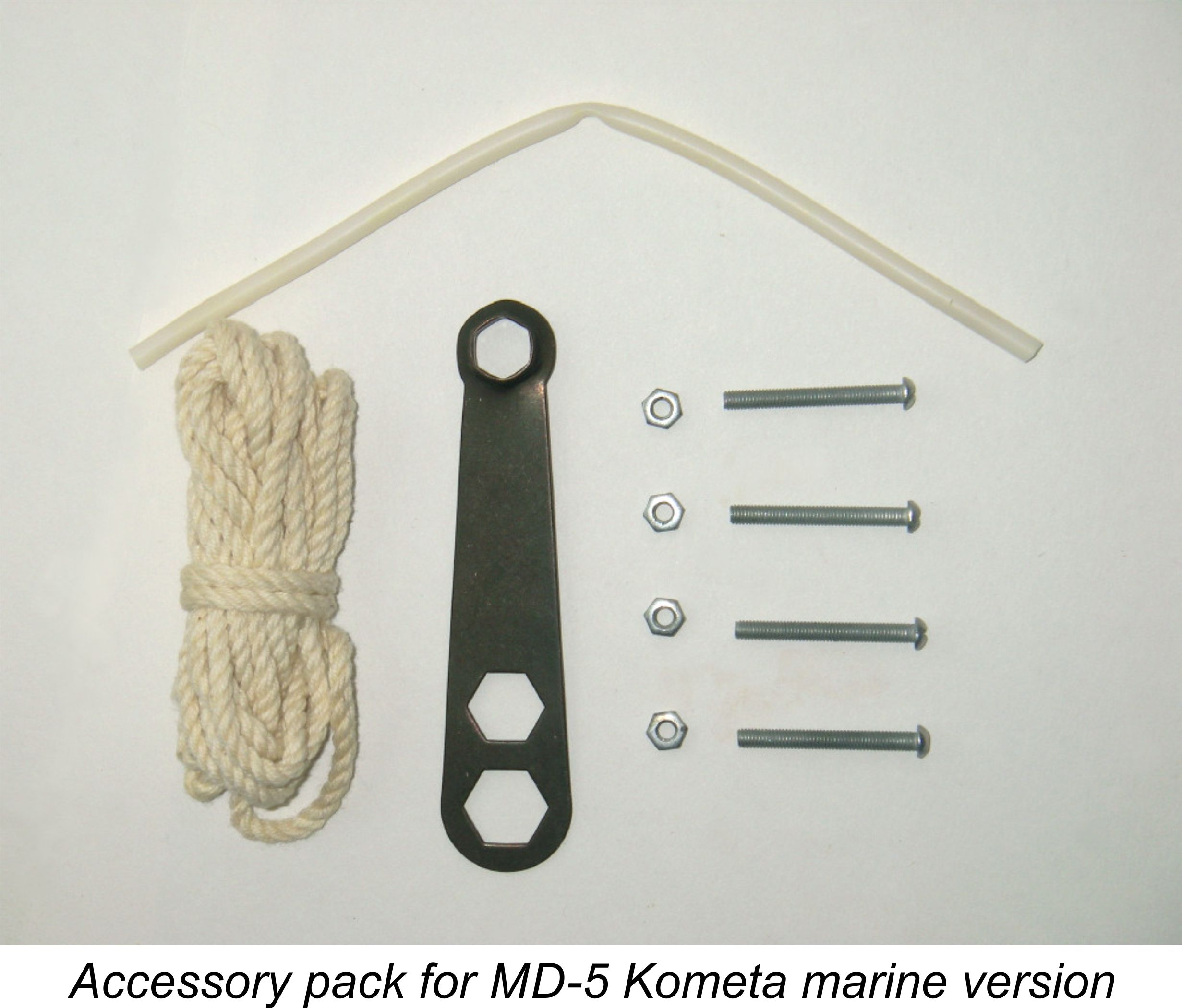
The author of the DOSAAF book reportedly cited an output of 0.50 BHP at 16,000 rpm for the Kometa, a figure which was included in the instruction manual which came with each engine when new. This figure actually has a rather more honest ring to it than the Super Tigre claim noted previously! In terms of their presentation to the customer, the majority of the engines came packed in a somewhat flimsy but colourful cardboard box with “Miniature Motor / MD-5 Kometa” (in Russian script, naturally) on the lid and the circled “H” emblem (pronounced as The engines came complete with a set of mounting bolts with nuts, a supposedly matching nylon airscrew, some amazingly crap-quality fuel tubing, a combination spanner of very indifferent quality and an alternative sleeve nut and washer for prop mounting. In the case of the flywheel-equipped “marine” versions, the airscrew and sleeve nut were replaced with a length of starting cord. Together with these accessories, a comprehensive Russian-language instruction leaflet was also included. Another interesting point was the recommended use of a fuel with ethanol as its basic ingredient as opposed to the more familiar methanol. Presumably ethanol was more readily available in Russia at the time. Prior to despatch, each engine was reportedly tested on a 75/25 mixture of ethanol and castor oil, but reference was made to the use of specialized fuels recommended by DOSAAF for higher performance. Oddly, there were no specific airscrew recommendations. The guarantee covered the engine’s first ten hours of operation or first year following its sale, whichever came first. Few contemporary manufacturers offered a guarantee of this scope, regardless of location. Interestingly, the recommended break-in was only 5 - 10 minutes of rich running!
The engines were made to a quite acceptable standard apart from the piston rings, which seem to have varied considerably in terms of fit and finish. Some of them were very well fitted as supplied - I have two examples in this category - but others appear to have left something to be desired in the compression department. The ball races too seem to be of somewhat “utilitarian” quality, although experience has shown that they stand up pretty well in operation. Otherwise, I’d objectively rate the quality of construction as perfectly satisfactory. Description of Variants As originally released. the design and construction of the Kometa followed that of the Super Tigre G21/29 almost exactly, to the point that most components were directly interchangeable. Accordingly, the description already given for the Super Tigre model applies equally to the Kometa, rendering any repetition unnecessary.
In years of looking, I have never seen any five digit batch numbers, making it appear unlikely that any one batch ever exceeded 10,000 units – most probably far less. However, four-digit batch numbers are very common in my experience, indicating that the number of engines in each batch ran well into the multi-thousands.
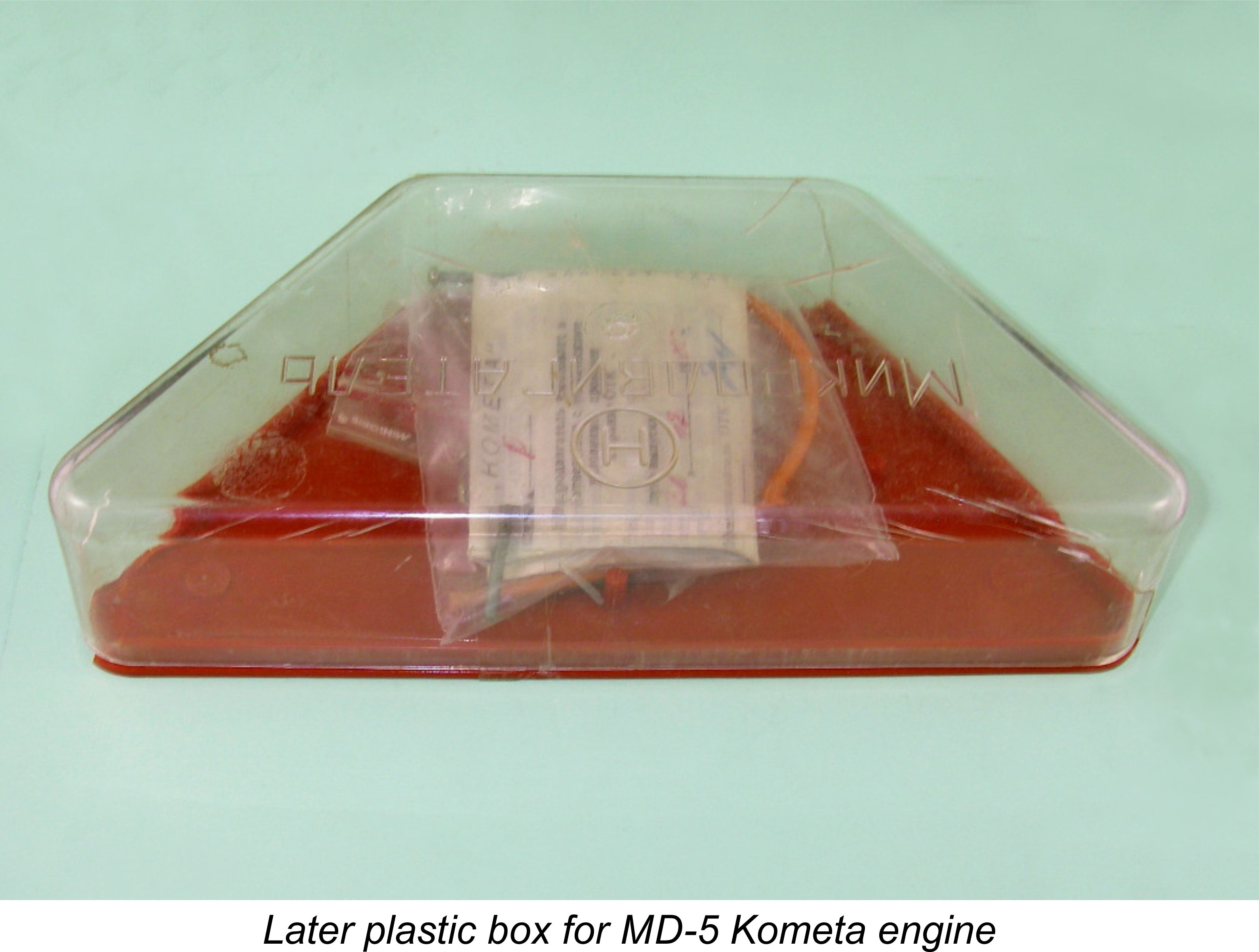
Later models dropped the serial number but continued to be associated with a letter which appears to have placed the engine within a specific series or design variation. The applicable letter was filled in by hand in a printed space designated “Series” (in Russian) on the instruction leaflet supplied with the engine. Many of the later examples also had their series designation letters stamped into the case in the former serial number location. Interestingly enough, one of the letters used was the letter “D”, which does not form part of the Russian alphabet, although I have one example which displays the letter “D” as its Russian phonetic equivalent “Д”. The variance in the rendering of the letter “D” implies that they may have used Latin characters to designate the various series for engines which were intended for export. The last series is definitely known to have been the “E” series – I have two such examples, one of which is a New-in-Box unit which is authoritatively paper-dated to 1992. It must be one of the last engines to leave the factory. Apart from the various production series, the engines were sold in two distinct configurations, which were indicated separately both on the box and on the instruction leaflet. Hence this letter should not be confused with the series designations. The “A” configuration was supplied equipped for aircraft use with the range of accessories described earlier, while the “M” configuration was supplied with a flywheel for marine or automobile use together with a female universal drive sleeve and a starting cord plus the standard spanner, fuel tubing and mounting hardware. Both types were air-cooled, with the M-series engines presumably relying upon the high-speed movement of the model to provide the required cooling airflow. The instruction manual states specifically that the M-configuration engines should not be run for more than 1 - 2 minutes without cooling airflow.
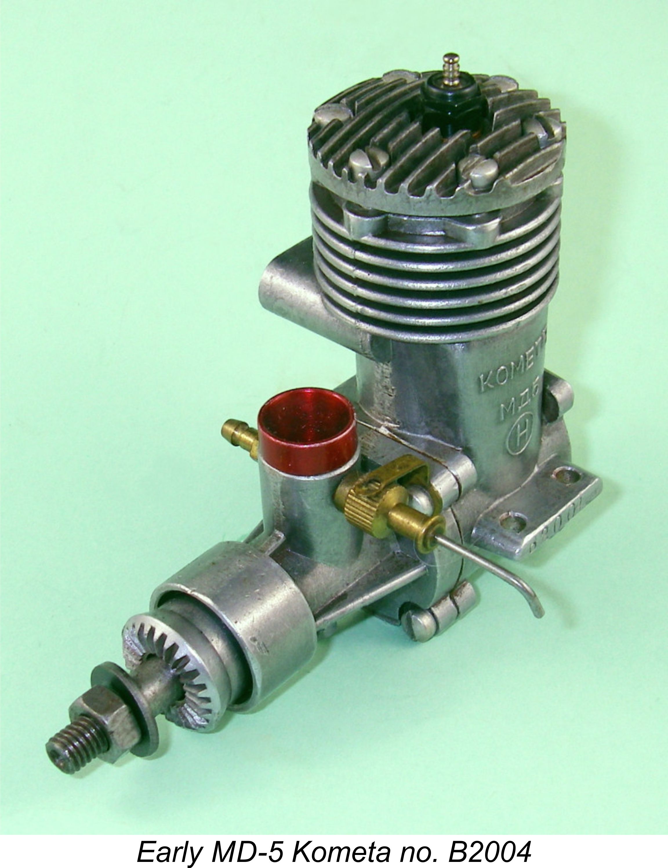
Nominal bore and stroke were identical to the Super Tigre original at 19 mm and 17 mm respectively for an identical displacement of 4.82 cc (0.294 cuin). The instruction manual gave the compression ratio as a range of between 7 and 8 to 1, presumably indicating the optimum range of compression ratios which could be adjusted by shimming of the head. The engine weighed in at a rather porky 7.9 ounces, a substantial proportion of which was accounted for by the very heavy shaft and ball race assembly. The original “speed” crankshafts were counterbalanced and featured a monumental 9 mm diameter internal Early models were definitely produced with “eye appeal” in mind – they had brightly finished cases along with very smart red-anodized cylinder heads and venturi inserts. There were two prop attachment options - the first was by means of an internally threaded sleeve nut with a hexagonal head section which screwed onto the front portion of the crankshaft in the conventional “racing engine” manner. This may be seen in the attached image of the example tested by Ron Warring in 1958. The alternative was a conventional prop-nut and washer. A cast aluminium prop driver was used on the early models, being continued for many years thereafter.
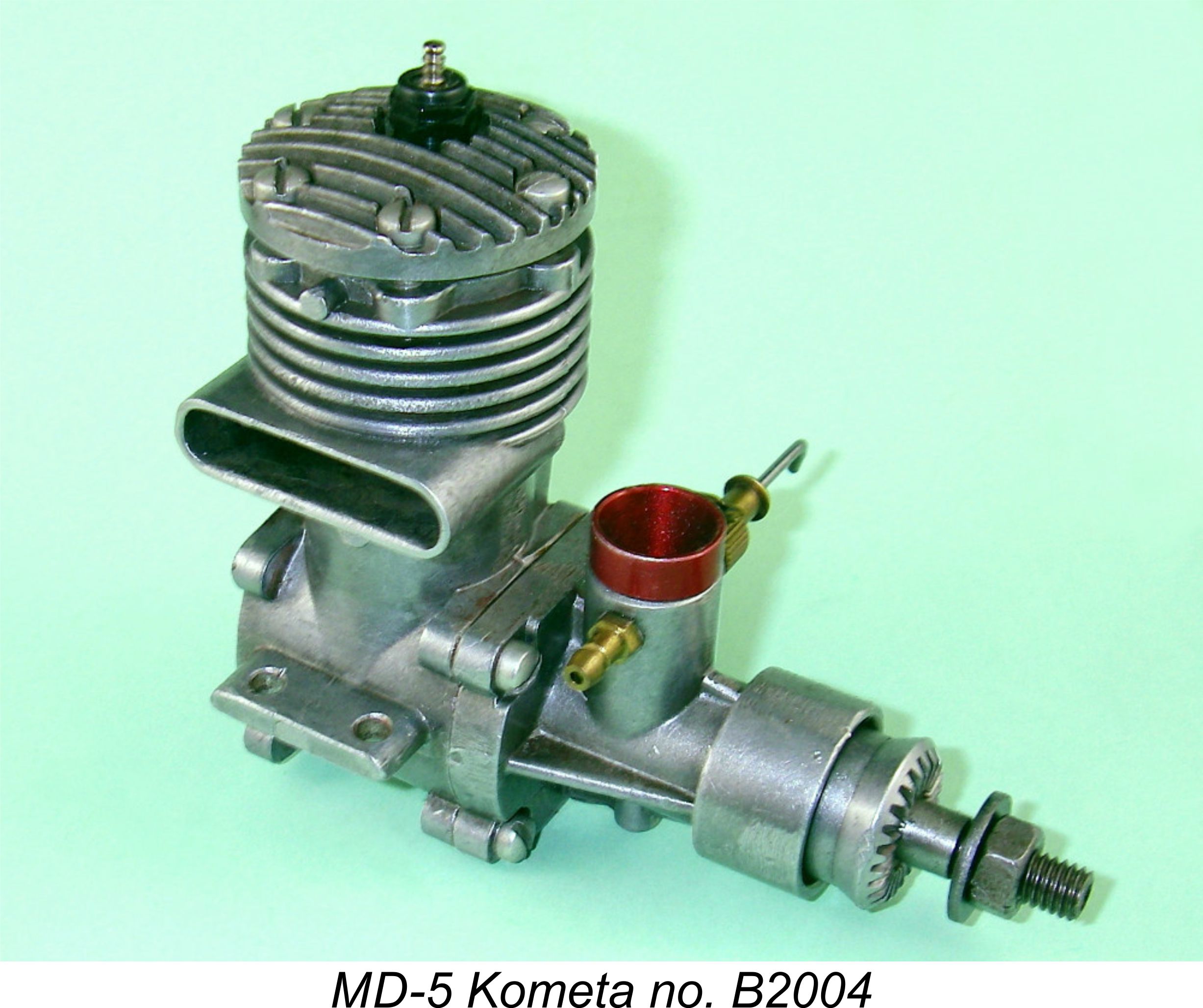
A series of progressively-introduced changes were subsequently applied to the original model. First, the heads were left plain without any colour being applied. Illustrated engine number B2004 is an example of this variant. Subsequently, the manufacturers began to leave the castings in their as-cast state rather than applying the original bright finish.
Later still, they began applying a vapour-blasting treatment to all of the castings to produce an At some indeterminate later The monetary values vary, clearly indicating different casting batches given the fact that they are cast onto the cases. Earlier engines bear the value of 9р.50 коп (9 roubles 50 crowns), but by 1980 the displayed value had jumped to 11 руБ (11 roubles) even! Now there’s inflation for you……………… On some of the “D” series engines (including one of my own examples), the circled letter “H” is omitted from the bypass inscription, although it re-appears on the cases of the later ”E” series models.
The later “E” series engines also featured a revised prop driver which was machined from bar stock rather The change to a lapped piston/cylinder combination belatedly followed the lead of Super Tigre, who had made this change many years previously. It’s important to note that the ring piston and lapped piston liners are not interchangeable between engines – the ring piston liner has unusually thin 1 mm walls which result in a nominal outside diameter of only 21 mm, while the lapped piston liner has a sturdy 2 mm wall thickness and hence an outside diameter of 23 mm. This reduces the bypass area somewhat in the lapped piston version. The cylinder porting in the lapped piston version also has considerably less area – by this time, it seems that the makers had given up on the Kometa as a racing engine. Despite this, they didn’t change the cylinder port timing nor the very radical crankshaft rotary valve timing, as they might well have done to good effect at this stage of development ......... From the outset, the manufacturers clearly envisioned the engine being used in a far wider range of applications than the prototype Super Tigre model. I already commented upon the engine’s successful use as Engines fitted with the “speed” liner appear to be relatively uncommon – the use of that component seems to have been confined to a proportion of the earlier examples, with the alternative “stunt” liner becoming increasingly predominant over time. This “stunt” liner did not have the extra transfer port cut into it on the transfer side. To partially compensate for this, the alternative liner terminated somewhat higher up the bore at its lower edge, thus reducing any tendency to obscure the entry into the bypass passage. This measure was rendered rather ineffective by the fact that the unsupported lower piston skirt simply took over the obstruction role at bottom dead centre! Oddly enough, the piston on these engines retained its piston port, although this no longer had a matching liner port with which to register. However, all was not lost - thanks to the raised lower edge of the liner, this piston port did open about half way at bottom dead centre, hence probably being worth leaving in if only to improve transfer to some degree, lighten the piston fractionally and promote better piston cooling and lubrication. Oddly, the “stunt” liner featured the same port timing as the “speed” liner.
The effect of these modifications was to reduce the rather excessive crankcase volume somewhat, a good move for stunt service. They also strengthened the shaft to a degree. However, it’s rather odd that the makers didn’t take the extra step of re-timing the rotary valve to make the induction timing more suitable for stunt. This would have been a very simply-implemented and highly effective modification. As it was, the same radical induction timing as used on the “speed” crankshaft was retained unaltered on the “stunt” unit. There appears to have been a certain lack of clear design focus here ..... In addition to the optional cylinder liners and crankshafts, the use of a separate venturi insert meant that a range of venturis having different bores could be fitted, although the engines appear to have been routinely supplied with the smallest-bore option. There’s little doubt that the makers expected the individual user either to bore out the venturi to suit the intended application or to have a range of inserts of differing bores on hand.
The underlying weakness of this multi-purpose approach was of course the induction timing, which was fixed by the crankshaft configuration. We already commented upon the unusually long induction period of no less than 215 degrees – the intake port opened quite early at 35 degrees after bottom dead centre and closed very late indeed at some 70 degrees after top dead centre. My own measured test example (see below) opens at exactly the design figure but closes some 10 degrees earlier at 60 degrees after top dead centre. Still pretty radical timing, with a very generous 205 degree opening period. In addition, the induction port and its associated 9 mm diameter passage in the “speed” crankshaft were extremely large, promoting very free breathing but making the crankcase volume substantially larger than average as well. When used with free-flowing intake and bypass arrangements, this overall set-up was of course quite appropriate for operation at high speeds – say around 16,000 rpm or above. But such arrangements are woefully unsuitable for slower-speed operation. It’s only necessary to look at this specification to predict with great confidence that low-speed performance of this engine would be well below average. This being so, it’s actually remarkable to recall the success of the Russian stunt fliers at the 1958 World Championships, who clearly managed quite well using these engines in their “stunt” configuration. Presumably they used low-pitch props operating at relatively high speeds. Some years ago, I tried my own “flier” example of the Kometa in a profile stunter using a 10x4 prop cut down to a wide-blade 9x4. It actually worked quite well using this airscrew along with a slightly larger-than-standard venturi insert. Unfortunately, I never recorded the ground and airborne rpm using this combination - I just recall that the engine ran quite fast in the air, exactly as intended, and that performance was very acceptable. The Kometa Diesel Model
The diesel version of the Kometa appeared in quantity in the Western marketplace during the early 1990’s after a large shipment had somehow been “relocated” from Russia to the West during the confusion of the late 1980’s when the Communist regime was in the process of breaking down. They were sold off at quite competitive prices by such firms as Carlson Engine Imports in the USA and Modusa & Co. in the UK. It took quite a while for stocks to become exhausted - Ed Carlson only sold off his The diesel version was essentially a lapped-piston “E” series Kometa with a diesel head. It featured the same piston/cylinder set-up and unbalanced crankshaft of the glow-plug model, but had a contra-piston lapped into the top of the cylinder. Oddly, this had a tapped hole in the centre which was sealed with a bolt and lock-nut! This most likely represented the maker’s approach to holding the contra piston while lapping it into the cylinder. The unfinned red-anodized cylinder head was basically similar to the glow head used on the lapped piston version of the glow model, but the compression screw was carried in a protruding tapped boss which took the place of the tapped recess for the plug. A test of this model by Dick Roberts was published in the September 1995 issue of “Aeromodeller” magazine. Interestingly, Dick claimed that the diesel version of the engine first appeared in the UK in 1962! I have been unable to find Dick was well satisfied with the results of his test, reporting an output of 0.345 BHP at 11,500 rpm. He stated that the engine was well made where it counted and would make an excellent engine for general-purpose flying using larger props. A 10x6 APC prop appeared to be more or less perfectly matched to the engine’s power delivery characteristics. Cold starting was apparently very good, although hot re-starts were somewhat less immediate. The main fly in the ointment was an appreciable level of vibration, doubtless due to the very heavy piston combined with the complete absence of any counterbalance on the crankweb. Production History One of the more remarkable aspects of model engine manufacturing in Russia is the unusually long production life of many of their designs. It appears that under the former Communist regime, large numbers of engines of various types (the MD-5 Kometa being only one of many) were mass-produced for distribution throughout the State-sponsored school and club systems to assist in the highly-valued technical education of Russian youth. The absolute performance of engines used for this purpose was relatively unimportant – all that mattered was that they ran reasonably well and could be easily and cheaply produced in quantity using straightforward equipment and techniques.
The inspection sheet with my own illustrated NIB “E” series marine version is factory-dated June 2nd, 1992, showing that at the very least factory distribution (if not production) was still ongoing at that time, some 35 years after the engine’s introduction! It is of course quite possible that this engine was a pre-1989 product from a batch which remained unsold as of 1989 and was sold off over the following few years, being dated as the individual units went out the door. But we can’t rule out the possibility that production at some level was still ongoing as of 1992. At the very least, the diesel conversion of some of the unsold “E” series glow-plug models may still have been taking place at this time. It’s unclear when production finally ceased, but it was probably not long if at all after 1990. All that can be said with certainty is that these engines were manufactured in quite large numbers over an unusually long period of well over 30 years. There must be tens of thousands of them still in existence – plenty to go round!! They are still encountered regularly today at swap meets and on eBay, many of them in new or near-new condition. Ron Warring’s Test Now we get down to perhaps the most interesting aspect of the matter - the thorny question of the Kometa’s performance credentials! Ron Warring’s test published in the November 1958 issue of "Aeromodeller" was conducted on one of the early models of the engine which was fitted with the “speed” liner and crankshaft along with the original needle valve with externally-threaded spraybar. The report contains a full description of the engine, which does not require repetition here.
Warring noted a number of factors which might have contributed to the sub-standard performance encountered. For example, he found that the needle valve assembly had been incorrectly adjusted prior to hard-soldering, to the point that it would not provide a sufficiently lean mixture. A replacement unit from a different engine was accordingly used for the tests. Warring also found that the rings in his test example failed to seal effectively, with consequent ill effects upon starting. He also commented upon the uneven finish of the piston working surfaces. Finally, and most significantly, he noted that the intake venturi was of a rather smaller size than would normally be expected for an engine of this size and potential. The induction timing of Warring’s example was as previously documented, hence clearly being optimized for high-speed running. It thus came as something of a surprise to Warring to find a peak output of only 0.234 BHP at a measly 13,000 rpm on Mercury no. 7 “racing” fuel. Most 2.5 cc plain bearing sports diesels of the day would easily beat those figures! At this point it’s interesting to recall Dick Roberts’ previously-mentioned 1995 test of the diesel version of the lapped-piston Kometa in which an output of 0.345 BHP at 11,500 rpm was recorded. This output was well in excess of that recorded by Warring for the ring-piston glow-plug model with its "speed" components. But once again, the peak speed recorded by Dick was clearly way below the speed for which the induction cycle was timed by the crankshaft. Dick’s diesel model did feature the later 8 mm diameter intake venturi, so that was not the cause of his relatively modest figures. The far smaller and hence more restrictive porting applied to the lapped-piston cylinder liner probably had a lot to do with the low performance measured by Dick, since such relatively restrictive porting scarcely matched the wide-open induction arrangements. The lack of counterbalance was doubtless also a factor, as was the absence of a piston baffle. Regardless of the reason, the fact remains that, like Warring, Dick recorded a peaking speed which was clearly way below the engine’s design potential. Returning now to the 1958 test conducted by Warring on the glow-plug model, Warring stated his view that the engine “should certainly achieve better figures”. Fair enough, but it didn’t do so! It follows logically that there must have been reasons for the unexpectedly-poor levels of performance, but Warring made no attempt to analyse the range of possible reasons. No doubt the leaky rings could have played a role, but one would think that Warring would have looked a little harder at these results and their possible causes. However, he did not do so – he more or less dismissed the engine as a sub-standard and overweight performer, and this damning verdict is how the engine has been remembered from that point on. Let’s see if we can do better ............... Where did Warring go wrong? When one considers the unusually wide range of uses to which the Kometa was explicitly intended to be put, it is rather extraordinary that Warring did not pause to consider that the results of his testing would be greatly affected by the overall configuration of the engine at the time of the test. For any engine to give its best in a given application, all of its design features have to be in harmony with one another. It’s abundantly clear that this was not true of Warring’s test example. It’s strange indeed that he did not appear to fully appreciate the implications of this situation or take steps to investigate its significance. As noted earlier, the engine tested by Warring was fitted with the so-called “speed” liner and shaft which were clearly intended for high-speed operation, as Warring himself recognized. In particular, the induction timing on his example conformed to the very radical figures set out earlier, providing a very clear indication that the internal geometry of the engine was specifically arranged for high speed running. Warring explicitly recognized this situation.
Warring noted that his engine was fitted with high-speed timing and porting, but also noted that it was fitted with a small “sport-sized” venturi insert. He did not give the size of this, but the original venturis supplied with all of the early examples of my acquaintance are of a mere 6 mm internal diameter – almost precisely the same 15/64 inch diameter used on the PAW 249 BR and other similar 2.5 cc diesels! It seems fairly safe to assume that the unit fitted to Warring’s example was of this size. This was used in conjunction with a 3 mm diameter spraybar ( 0.118 inch) – again, relatively typical of 2.5 cc diesel practise. And it only got worse with the later models – they retained the 6 mm venturi but use a thicker 4 mm diameter (0.157 inch) spraybar! Whoops, there goes a bunch more of our effective intake area.......!! The attached image (left) of the venturi on Anyway, here was Warring testing a 5 cc glow-plug engine which was based on a high-performance prototype and was very obviously timed to run at speeds in the order of 16,000 rpm or more but which was expected to breathe adequately through an induction system which would have been considered more or less acceptable for a general-purpose diesel engine of half the displacement typically operating at a substantially lower speed! It’s remarkable that anyone as knowledgeable as Warring would have found it surprising that such an engine would run out of breath long before reaching the speeds for which it was internally arranged. Warring made no attempt to conduct an analysis of the above kind, simply commenting that he did not know whether he had a “correctly matched combination”! A little thought would surely have brought him to the conclusion that he clearly did not have such a combination! However, it’s completely unfair to blame Warring greatly for this. After all, he did test the engine “as supplied” and did faithfully report his findings. The missing element in his report was his failure to present the simple analysis which would have demonstrated that when it came to low and moderate-speed operation of this engine, there was no “correctly matched combination” - the internal geometry of the engine simply made it completely and irredeemably unsuitable for such applications. It should have been abundantly clear that the manufacturers expected the user to optimize the intake diameter to suit the intended application, a process which Warring failed to explore. Indeed, in his 1958 book on model engines which may be found elsewhere on this website, the well-known Russian control line speed flier Oleg K. Gajevski explicitly stated that setting up his engine for best performance in the intended application was one of the modeller's prime responsibilities. Even without taking such a step, Warring’s report would have been rendered beyond criticism if he had simply added the comment that the configuration in which he tested the engine was clearly very far from optimum and hence yielded results which must inevitably fall well short of the engine’s true potential. Regardless, Warring’s highly negative report has damned the poor old MD-5 Kometa from that day to this, while Dick Robert’s 1995 test of the diesel version did little to alter that impression. My purpose in writing this article was largely to set the record straight by finally doing justice to what I sincerely believe has been a very much under-rated product of the oft-maligned 1950’s Russian model engine industry. Stu Richmond Pours Gasoline on the Flames Meanwhile, back in the USA ..........the reputation of the Kometa took another hard knock through the March 1990 appearance of a further test by Stu Richmond. This was part of Stu's series of such tests entitled "Engines of the World" which appeared periodically in the pages of "Model Builder" magazine for some years. If Warring's test report had been damaging, Richmond's far later effort was downright derogatory. Stu opened his salvo with the bald statement that the Kometa was "one of the world's worst engines". Seemingly he'd never heard of the Gotham Deezil or the G.H.Q. ............... He recorded the fact that he had three different versions of the engine on hand, but made no attempt to differentiate between them on any rational basis, as I did earlier in this article. Stu then proceeded to pour scorn on the engine's standard of construction in a number of areas, blaming the capabilities of its manufacturers along with the then-crumbling Soviet Command Economy for most of the problem. It may have been fashionable in America at the time to denigrate the Soviet system and the capabilities of its participants just as it was in the process of disintegrating, but such idealogically-biased criticisms scarcely belong in a model engine review - this after all was the same nation that brought us the excellent Kharkov MK-25, MK-17 and KMD 2.5 models, among numerous others. The impression gained from reading this review is that the writer was actively seeking every opportunity to comment negatively upon the capabilities of the Russians and the system which they were then in the process of abandoning. As such, the objectivity of the review appears highly questionable. Stu commented that the same manufacturing facility had been responsible for the 2.5 cc Meteor glow-plug and diesel models, which he characterised as being "just as awful". Not my experience at all, as recorded elsewhere ............... He quoted an English correspondent of his as stating that "they make 'em with hammers and cold chisels" - an outrageously untrue statement with which Richmond nonetheless expressed his complete agreement. To add to the mis-information, Stu got the introductory dates wrong for both the Meteor and the Kometa. When it came to running the Kometa, Stu did grudgingly admit that once the engine was run in, 2- or 3-flick starts were the norm. The engine turned a 10x6 Master airscrew at 9,400 - 9,600 rpm, while a 9x6 prop got up to 10,800 - 11,000 rpm. The Kometa managed 13,400 to 13,600 rpm on a 9x4 prop, but at those speeds vibration had become a serious issue, leading Richmond to quip that "a Richter Scale in Central Florida would have gotten a reading"! He terminated his testing at that point, citing an output of 0.25 BHP @ 12,000 rpm on an unspecified basis. Richmond concluded his "analysis" by presenting a calculation which determined that if one travelled to Moscow and purchased a Kometa there from a store, one would pay the princely sum of US$1.76 for the privilege. He commented that this sum was "about what it's worth". In my opinion, so was his review ............ With Warring's very modest findings and Richmond's overtly derogatory dismissal on the record, it was clear that it would be necessary for me to conduct a present-day test of a representative example of the Kometa. Since I had a number of these engines on hand, none of which exhibited anything like the quality issues cited by Richmond, this became a simple matter of selecting which one to use. The Kometa re-evaluated
Reference to Maris Dislers' invaluable Intake Choke Area Calculator revealed that the combination of a 7 mm dia. venturi with a 4 mm dia. spraybar provided an effective choke area of 12.093 mm2. A 4.82 cc engine should be readily useable in an aerobatic application at all speeds above 13,549 rpm with adequate suction. I always ran the engine in the air at higher speeds than that, hence finding that the Kometa performed well in this service. A 9x4 prop seemed to suit it perfectly - the low pitch was adequately compensated for by the higher operating speed. However, I still had the original 6 mm diameter item. After due consideration, I decided to employ this well-used engine for testing purposes. Although its original rings were a little worn from use, it still started and ran perfectly using those rings. It’s clear that by no means all examples suffered from the ring sealing problems encountered by Warring - several new un-run examples in my possession exhibit excellent compression even without any running-in to bed down the rings. However, as a first step the test engine was fitted with new Frank Bowman rings. I took this step because I wanted to give the engine the best possible chance to show what it could do and also wanted to test the quality of Frank’s rings, of which mine were the first batch that he made for the Kometa. With the new rings fitted, compression seal was excellent from the outset and only got better with running time. Good job as always, Frank! I also took advantage of the opportunity to replace the crap-quality Russian assembly screws (Richmond was right there!) with high-tensile socket head items - something that I should have done long ago.
I began with the stock 6 mm venturi in place together with the 4 mm spraybar. It’s really hard to believe that the engine was actually supplied in this configuration – how anyone could expect it to run at anything even approaching its potential is beyond me! But it was supplied like this, presumably for sport or stunt use, and so were many others. So ........... on with the test!! I used an oily fuel with a 10% nitro content and a plug in the middle of the heat range. Starting was a snap thanks to the excellent seal provided by Frank’s fine rings – one or two flicks every time following a prime. Again, Stu Richmond was spot-on. After a 45 minute break-in period to bed the rings in properly, compression was pretty much up to lapped piston standards! So I tried a few typical 5 cc props, with the following results (estimated power figures in brackets): Taipan GF 9x6 – 9,800 rpm (0.236 BHP) Taipan GF 9x4 – 11,300 rpm (0.270 BHP) Taipan GF 8x4 – 13,200 rpm (0.274 BHP) Oh dear!! Very consistent with Warring’s results……..... almost all of my 2.5cc diesels will match or handsomely beat these woeful figures! The engine appeared to be past its peak already at 13,200 rpm, having probably reached a peak output of no more than some 0.290 BHP at around 12,700 rpm. Added to which, the engine exhibited a tendency to misfire which could not be eliminated at any setting of the needle. I tried changing plugs, but this made no difference. So I packed up and went home, feeling more than a little chastened ......could Warring's dismissal of the engine have been justified after all?!?
Reference to Maris Dislers' Choke Area Calculator revealed that the combination of an 8 mm dia. venturi with a 4 mm dia. spraybar gave an effective choke area of 19.654 mm2. This would allow operation of a 4.82 cc engine on suction fuel feed at any speed above 8,359 rpm, albeit with borederline suction. I was quite certain that I would be operating the engine at speeds well above this figure! The component fitted perfectly, and I was all set for a re-test, still using the 4 mm diameter spraybar. This time, I took along some hot fuel with a 30% nitro content as well as the 10% brew formerly used. I also decided not to bother with props other than the 8x4 – I didn’t want to beat this old warrior to death, and it was high-speed performance in the region of the engine’s peak that I was looking for on this occasion. A Taipan 8x4 GF is a good test prop for a 1950’s vintage 5 cc racing glow engine in my experience – they tend to turn such a prop at somewhere near their peaking speed. I stared with the same 10% fuel that I had used on the previous occasion. Even on this fuel, the Kometa was completely transformed! That annoying misfire was gone completely, and the engine needled flawlessly while running as smoothly as one could wish. Suction remained more than adequate – no excessive withdrawal of the needle was required, while moving the tank up and down failed to greatly upset the engine until the change in level became quite pronounced. In fact, based on my own extensive experience of bench-testing and flying stunt glow-plug engines, I gained the impression that the 8 mm venturi with the 4 mm spraybar would probably work just fine in an aerobatic application using a suitably designed and positioned tank along with a high-speed prop. With a 3 mm spraybar as used on the early engines, a 7 mm venturi would probably be ideal. Indeed, that was the set-up with which the original Super Tigres were supplied.
I then fitted a cold plug and tried the engine on the 30% nitro brew that I had brought along. This time, it got the same prop up to 16,500 rpm without excessive leaning out (in deference to its age and the relative newness of the rings). So the extra 20% nitro yielded at least an additional 1,100 rpm on the same prop along with an increase in power output to around 0.534 BHP at the higher speed. The engine showed no signs of distress at the tested speed, holding its note very steadily. It seems that the Russians themselves must eventually have realized the benefits of using such a venturi – as noted earlier, the 1992 marine example in my collection has an original Russian venturi of 8 mm internal diameter in combination with a 4 mm spraybar. The diesel versions of the “E” series model also featured the 8 mm venturi. However, both of these models featured the later lapped piston/cylinder combination with its far more conservative porting. Greatly encouraged by this success, I ransacked the Super Tigre parts bin some more and came up with a monster 9 mm I/D venturi, again originally intended for the Super Tigre G21/29 - a further 25% gain in throat area over that provided by the 8 mm item and 125% greater than that of the original 6 mm component. Maris's calculator told me that this combination would increase the effective choke area to 28.840 in2, raising the minimum operating speed with bordeline suction to 12,266 rpm. I installed this venturi and headed back out to try again. If confirmation was needed of the complete dependence of this design upon a free-breathing induction system, this was it! On the 10% nitro fuel, the engine got the test 8x4 prop (the same one used throughout) up to an effortless 16,800 rpm and 0.564 BHP! This represents an honest gain of some 3,600 rpm on this prop over the speed obtained on the same fuel with the original 6 mm venturi fitted. But even this paled in comparison with the results obtained on the 30% nitro brew. Using this potent blend, I clocked a genuine 18,000 rpm on a very slightly rich needle!! This is getting way up into Dooling, McCoy, ETA and original Super Tigre territory - we’re looking at an output of around 0.694 BHP here! The engine sounded quite untroubled at this speed, holding its (very loud!) note perfectly with no sagging or tightening up (admittedly with the needle kept a tad rich). No structural or wear problems of any kind were apparent following the test - the engine felt first-class. Nor was vibration a noteworthy issue - the combination of a very light piston with the counterbalance on the speed shaft appeared to be very effective, at least at this speed. I can only assume that Richmond's example had the unbalanced shaft fitted.
The carburettor boss into which the venturi fits has an internal diameter of 12 mm, allowing the use of a venturi insert of up to 10 mm I/D while retaining a 1 mm wall thickness in the spigot section. There’s little doubt that with such a venturi on pressure feed, and perhaps with a thinned spraybar, the Kometa would give a very good account of itself by 1957 standards! As it stands, the above figures lend a good deal of credence to the Russian performance claim mentioned earlier – in fact, they suggest a significantly higher level of potential performance than that claimed by the Russians! The various reports of the Kometa having been used as a speed engine have hitherto appeared highly questionable or even laughable on the basis of Warring’s test. However, my own results reported above show that a well set-up and carefully-tuned Kometa fitted with the “speed” cylinder and crankshaft and running on pressure fuel feed could indeed have delivered a quite respectable performance in that context by mid to late 1950’s standards. I know full well that the above does not represent anything even approaching a comprehensive test of the engine. What it does do is demonstrate convincingly that this is a high-speed engine which needs to be allowed to breathe in order to give of its best. In the configuration in which Warring tested it, there was no possibility whatsoever of its coming anywhere near its true potential. Moreover, this should have been quite obvious to Warring. It appears that his reported figures for the engine as tested were probably completely accurate, but those figures raised more questions than they answered. It’s a pity that Warring didn’t go further in search of some answers……………… These findings appear to be supported by a later comment from Peter Chinn. In an article entitled “Iron Curtain Engines – Da? Nyet?” which was unattributed but which was almost certainly ghost-written by Chinn for “American Modeller” magazine and published in their August 1962 issue, Chinn described and illustrated the MD-5 Kometa, commenting that it had been “quite widely used by the Russians, with minor modifications, for stunt, speed and speedboat work”. He also quoted the Russian performance claim mentioned earlier, stating that “from tests we have made, the Russian claim of 0.50 bhp is not unduly optimistic for a reasonably good example running on about 30% nitro”. Very much in contrast to Warring’s verdict and Richmond's later condemnation, but completely in line with my own findings ……. it seems that Chinn went further into the matter than Warring. Too bad that he never published a full test report! So You Want to Run or (gulp!) Fly a Kometa??
For all-out competition use, the old speed engine tuner that still lurks within me can see quite a few things that could be done to the Kometa to improve performance still further. But I can’t really recommend going that route with these old classics – we should use them in a manner that conserves them in their original state for as long as possible. Conclusion I hope that the above article has convinced a few readers that the poor old Kometa hardly deserved the criticism of its performance that appeared in Warring’s and Richmond's reports. In fact, it appears on balance to have been one of the better Russian manufacturing efforts of its era. Warring’s test example did undoubtedly suffer from some quality control issues, as no doubt did a good few others, but these were by no means universal. Once properly set up, many of these engines must have given quite satisfactory service to their owners in Russia and elsewhere. Chinn’s later comments regarding the widespread use of the engine certainly implied as much, as did the results achieved at the 1958 World Stunt Championships.
That said, it must be recognized in defence of the manufacturers that they did provide what was basically a sound product having a good performance potential combined with adequate structural integrity. Moreover, they may well have anticipated that the engines would be widely used by novice flyers and that as these individuals gained experience with their engines they would acquire sufficient understanding of their business to optimize the venturi diameter to suit the intended application. In selling the engine with a smaller-than-optimum venturi, they were supplying it in a docile form suitable for novices to tackle the possibly daunting task of learning how to start and operate a 5 cc glow-plug engine while also leaving all tuning options open – you can progressively enlarge a venturi easily enough, but replacing metal once removed is less straightforward! Which points to the only other potential villain, albeit a relatively minor one in my book - Warring himself, who openly noted the anomalous nature of the results that he was getting but stopped short of analysing and testing the potential (and rather obvious!) reasons for those results, thus leaving modelling posterity with a condemnation of the Kometa which it scarcely deserved. Hopefully this article will have set that right after all this time! Kometa an engine worth using?!? Da, da, kamerad!! _________________ Article © Adrian C. Duncan, Coquitlam, British Columbia, Canada First published December 2014 |
 In this article we look at a glow-plug engine from the 1950’s that really took it on the chin in its one and only published test appearance, subsequently faring poorly in articles on model engines in general. Despite this, it had the last laugh on its competitors by outliving the lot of them in production terms. We’re talking about the Russian-made MD-5 Kometa 5 cc glow-plug motor, widely viewed today as just another member of the extremely prolific Russian Loadakrap range of the mid 20
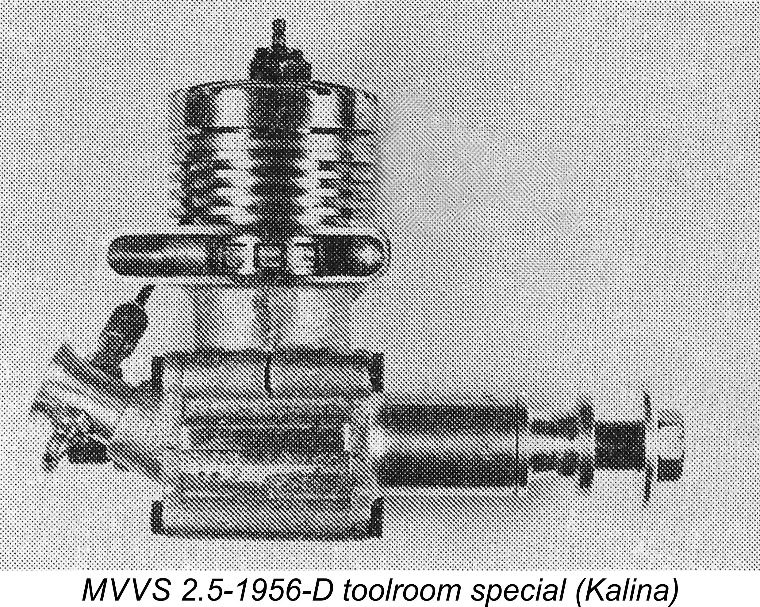 The Iron Curtain “specials” of this era were very much products of their time and place. They were not manufactured on any kind of commercial basis – instead, they were individually produced in very small numbers purely to supply world-class engines to the select few model flyers from their countries of origin who were judged to be sufficiently skilled to use them to win International competitions. The objectives were largely political - the showcasing of the technical capabilities of the Communist regimes under which Eastern Europe was then living behind the Iron Curtain. No doubt there was also a strong element of national prestige involved for the individual countries concerned - Communism didn’t entirely eradicate national competitiveness!
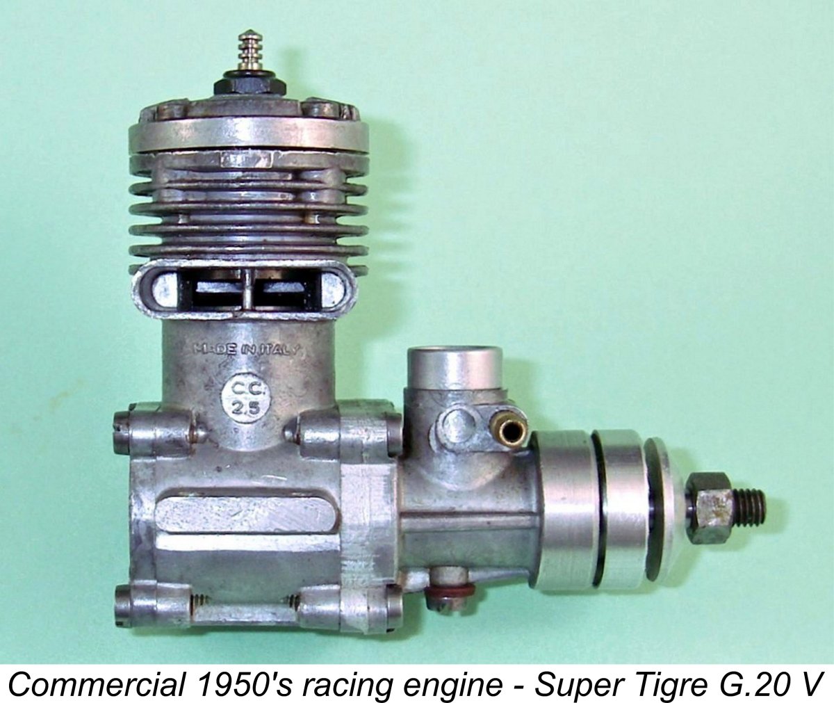 By contrast, Micromeccanica Saturno was very much a commercial enterprise which had been established for the very practical purpose of making money through sales of model engines to the general public. Their motivation for competing at the International level was far more down-to-earth than that of their Iron Curtain competitors – they simply wanted to swell their revenues through increased sales of their engines, quite justifiably seeing competition success at the International level as representing the best possible opportunity for promoting their products worldwide.
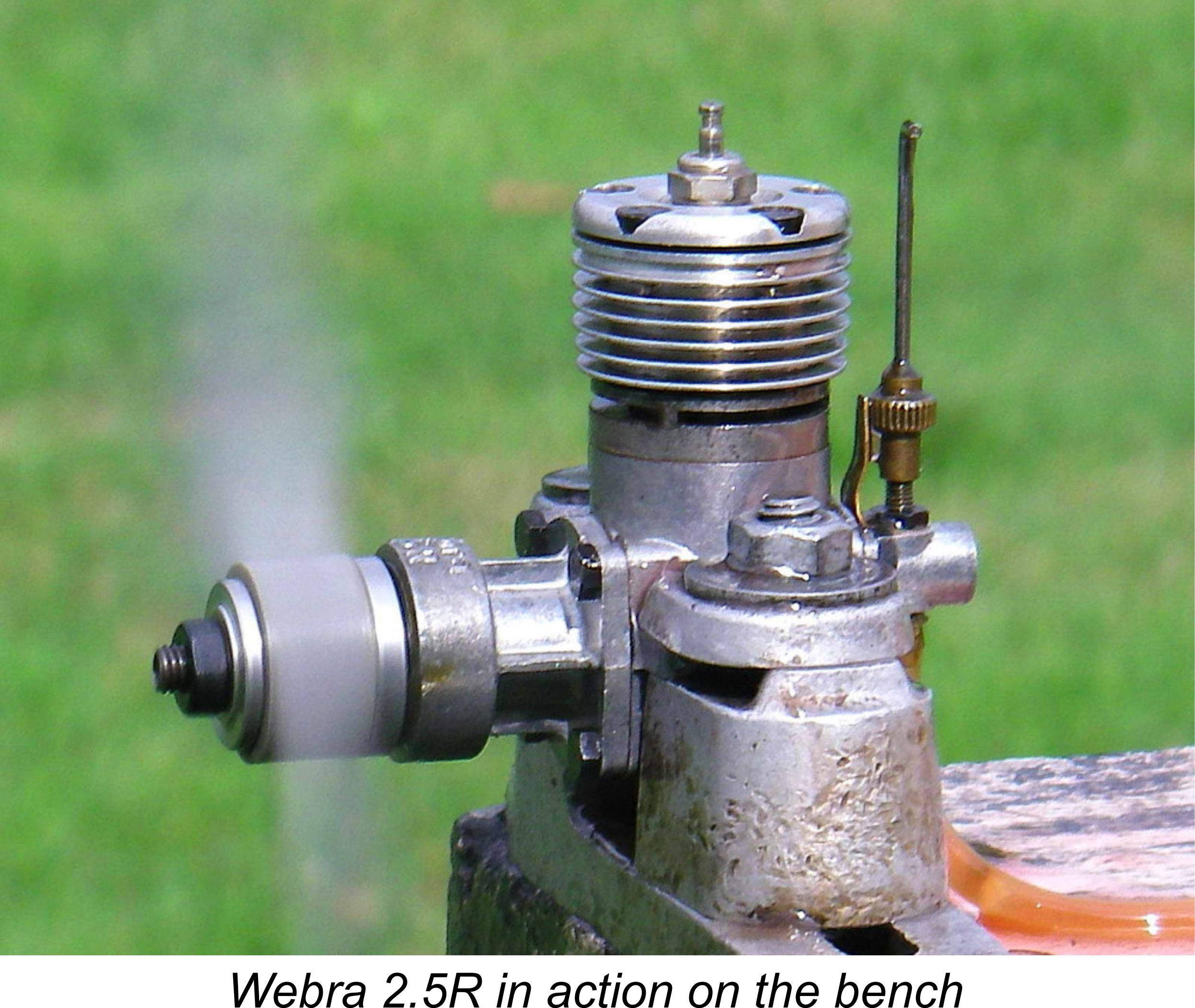 The vast majority of would-be contest modellers in the Iron Curtain countries were far less fortunate - they had no access whatsoever to the state-sponsored tool-room specials which upheld the honour of their countries on the International contest field. Moreover, competition engines from beyond the Iron Curtain were neither affordable nor even available through “official” channels.
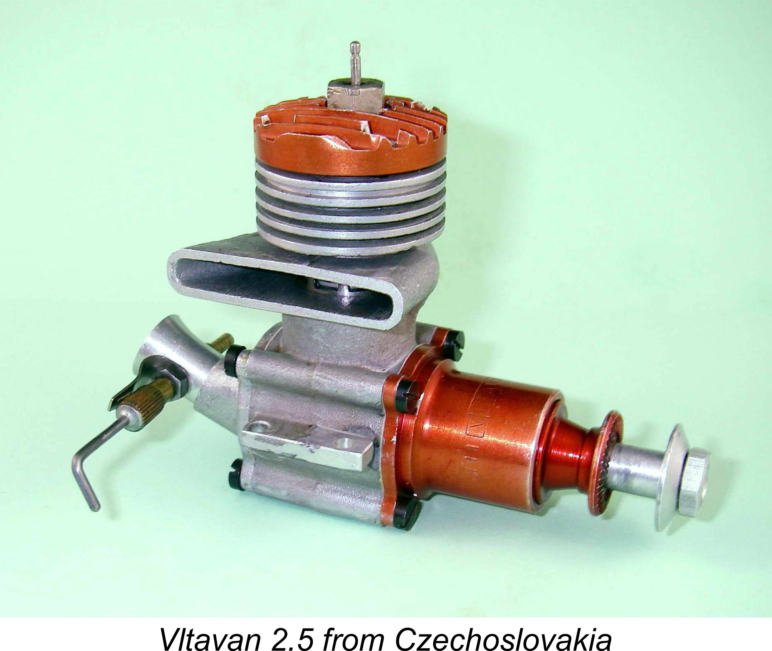 During the latter half of the 1950’s, steps were taken by several Iron Curtain regimes to redress this situation through the development of facilities for the express purpose of mass-producing “consumer grade” contest engines which could be made available to a far broader spectrum of the modelling public in the Communist sphere of influence. At this stage, there was no thought of undertaking any primary development work at these establishments – they would simply manufacture consumer-grade copies of established designs. The resulting engines could be distributed both at the retail level under Government license and through the State-sponsored school and club systems.
 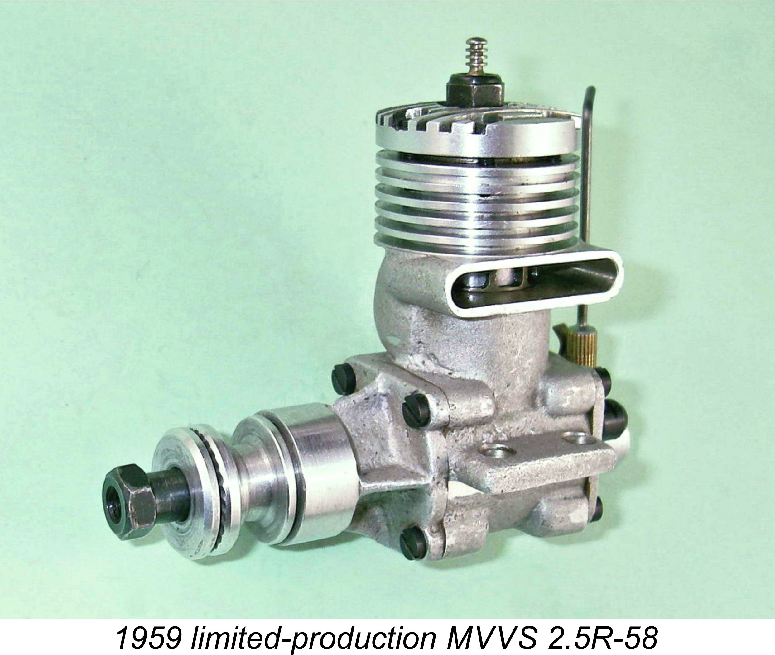 In several separate articles to be found on the MEN web-site, we have examined the approach taken by the Czechs to the adoption of this strategy. Their Vltavan series of production-line MVVS copies which was manufactured between 1957 and 1959 doubtless made a worthwhile contribution towards meeting the goals stated above. I've recounted the stories of the
  were rather antiquated in design terms, to the point that none of them could by any stretch of the imagination be called competition engines.
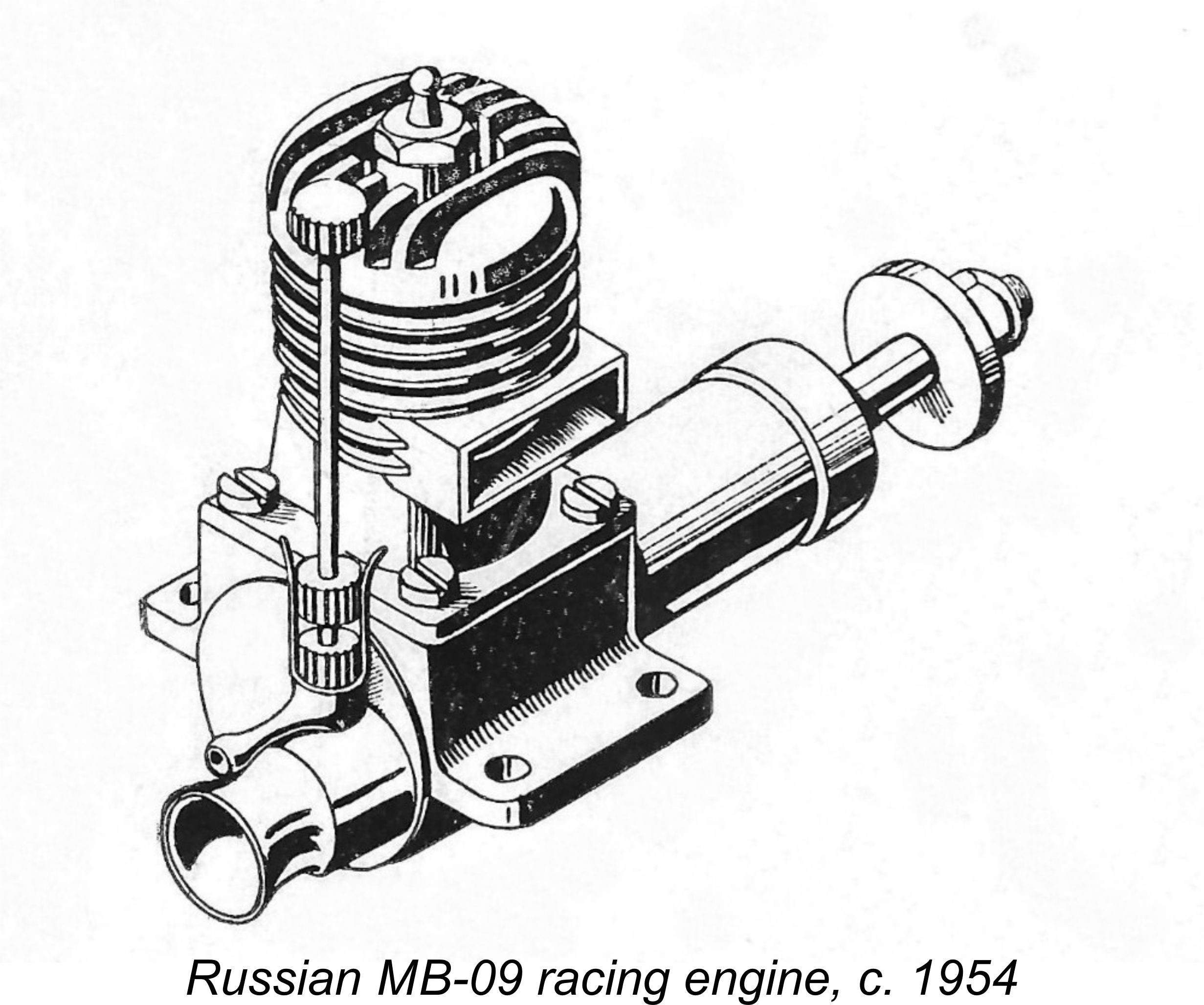
 The Czechs were already making plans to commence the manufacture of their Vltavan consumer-grade versions of the 2.5 cc and 5 cc MVVS engines, and at this point in time the Russians did not want to interfere with that initiative – the Communist states were supposed to stand shoulder to shoulder and compete against the rest of the world rather than against each other! But there was an excellent alternative – why not copy well-established and demonstrably successful engines from beyond the Iron Curtain? Much might be learned from such an approach ……..
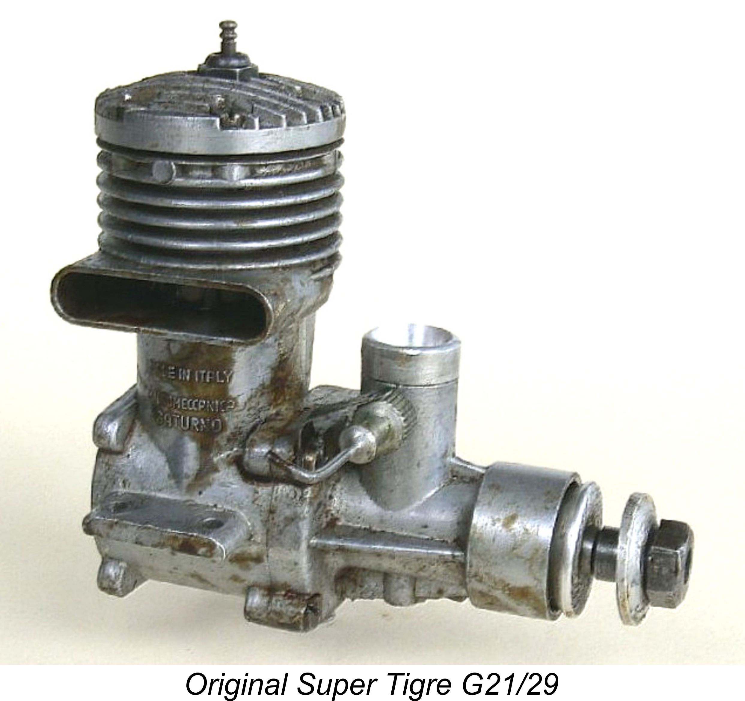
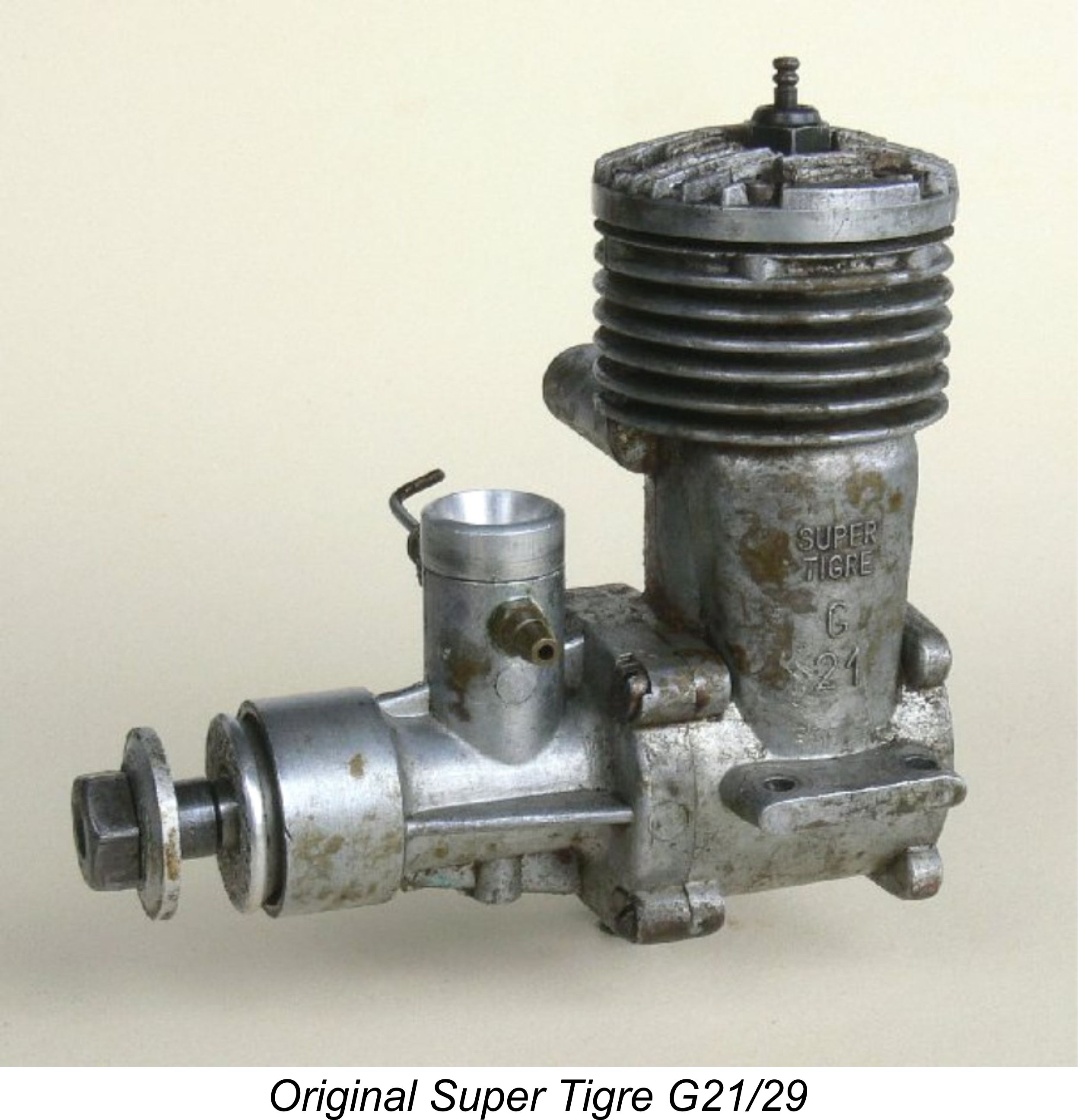 It will always remain unclear why the Russians chose to take the 5 cc Super Tigre G21/29 of 1954 as the model for their first competition glow-plug engine to be scheduled for quantity production, since 1954 had been the final year in which the control-line speed World Championships were contested in the 5 cc class. Beginning in 1955, the International class was firmly established as being restricted to engines of 2.5 cc displacement. At first sight it would thus appear more logical to have taken an established 2.5 cc model as the prototype.
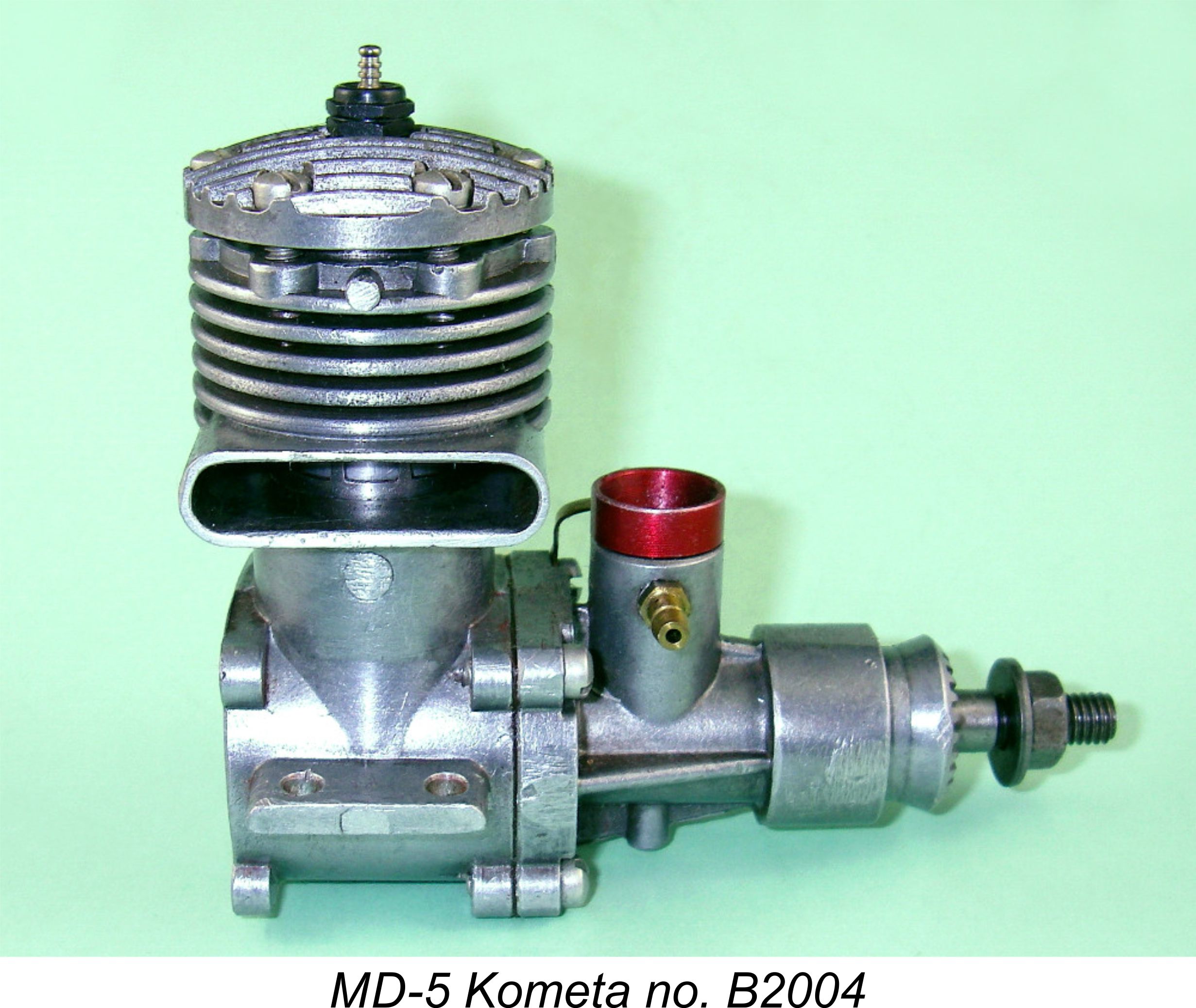 Although it’s very difficult to be absolutely certain, it appears from what little is known that the quantity production of the MD-5 Kometa most probably began at some point in 1957. Certainly, the engine first came to the attention of modellers in the West in early 1958. As was so often the case, Peter Chinn was among the first Western commentators to examine the engine in detail, describing and illustrating it in his “Latest Engine News” column in the April 1958 issue of “Model Aircraft”.
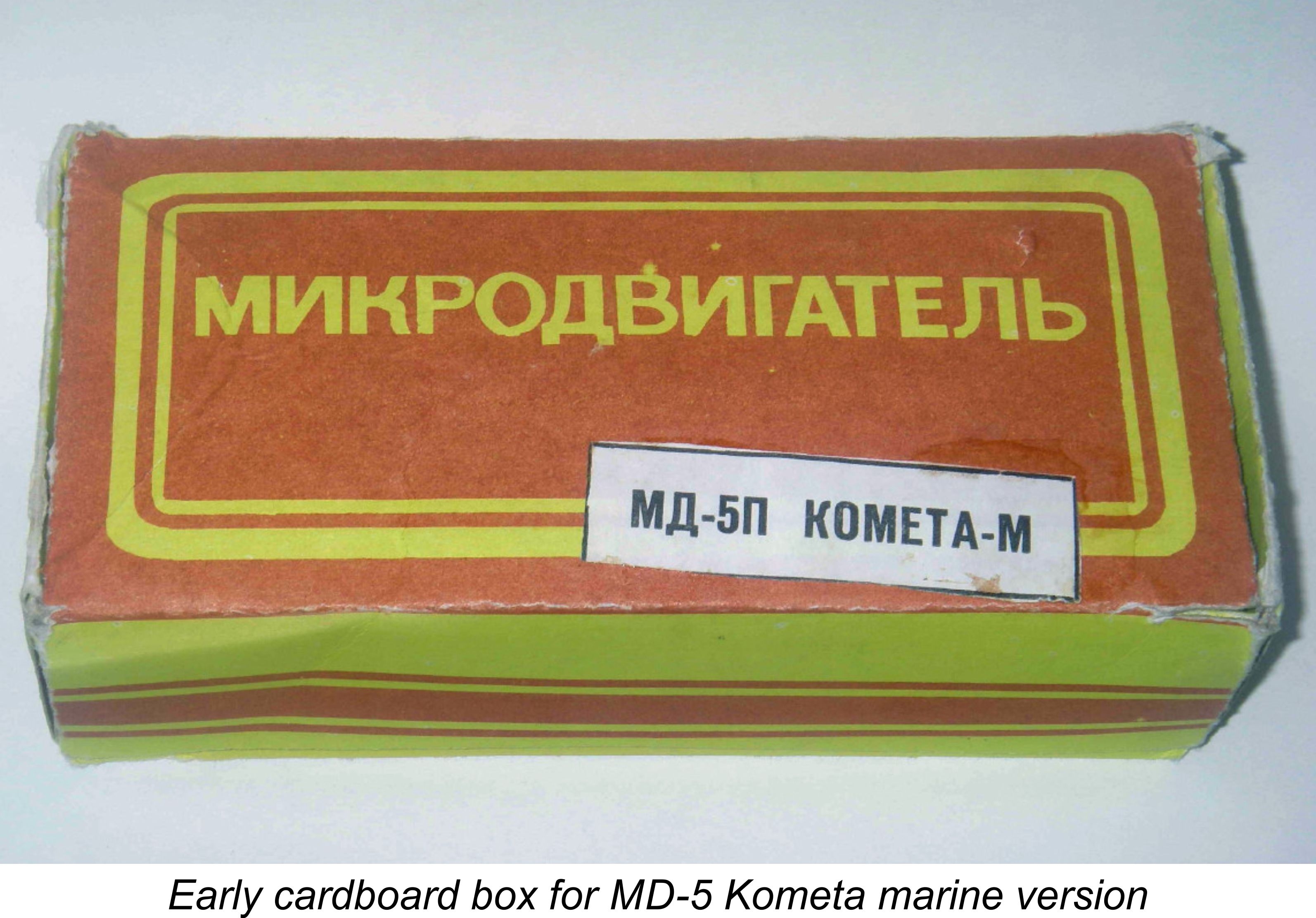
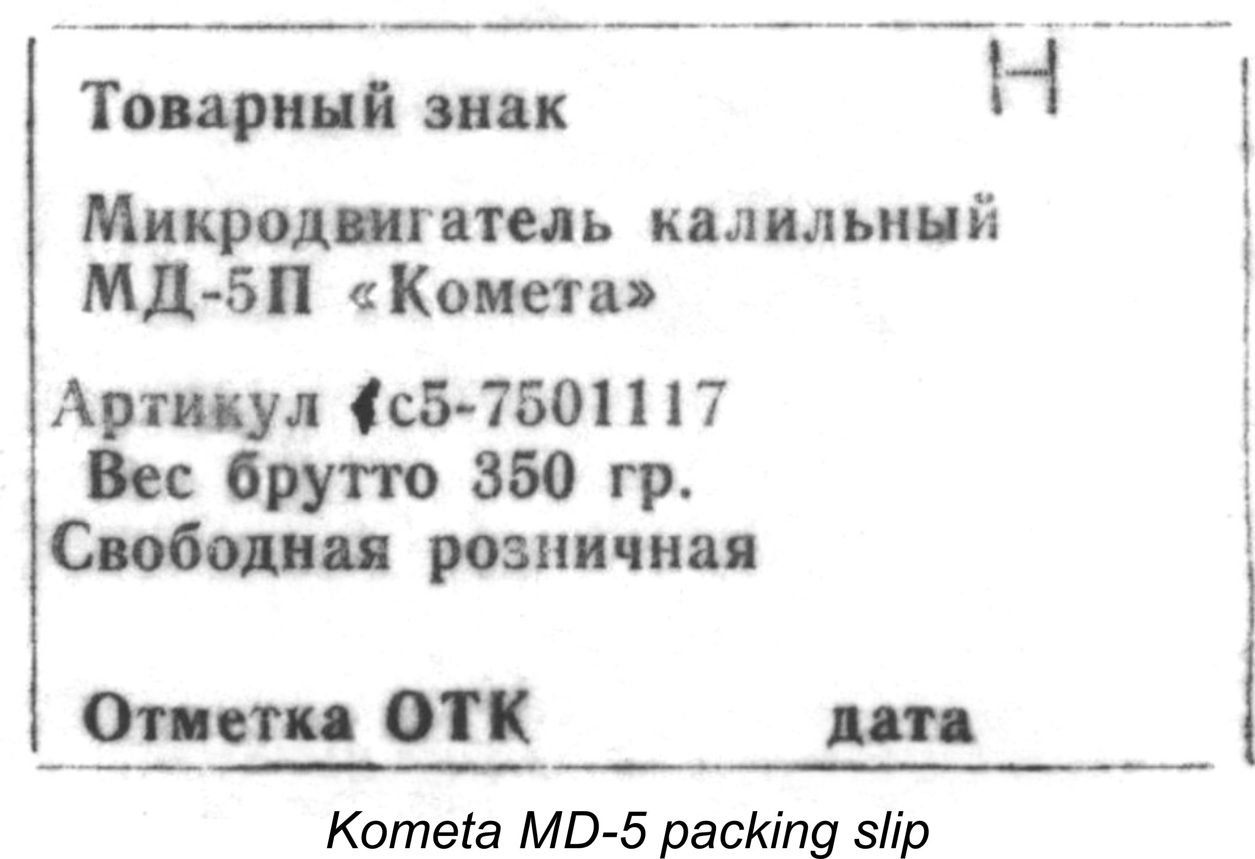 A reminder of the fact that these engines were produced under the former Communist regime was the inclusion in each box of a small certificate assigning a Government article number to the Kometa and certifying that the designated article had been cleared for retail sale. Only articles which had received this official sanction could be openly sold on the retail market during the period in which the majority of these engines were produced.
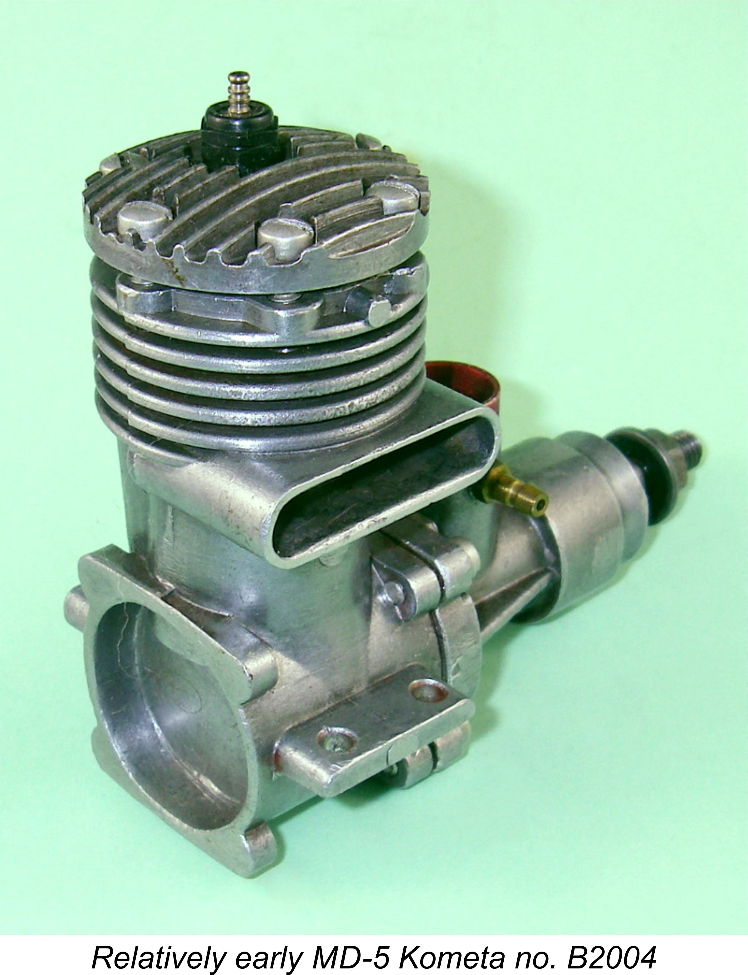 The earlier examples of the Kometa bore serial numbers which began with a letter followed by the number itself. It appears that these early engines were made in distinct batches which were indicated by a letter (presumably starting with A for the initial batch since A is the first letter of the Russian alphabet). The position of the engine within that batch was then indicated by a number, with the letter and number combining to form the serial number. The numbers were stamped onto the outer edge of the left-hand mounting lug.
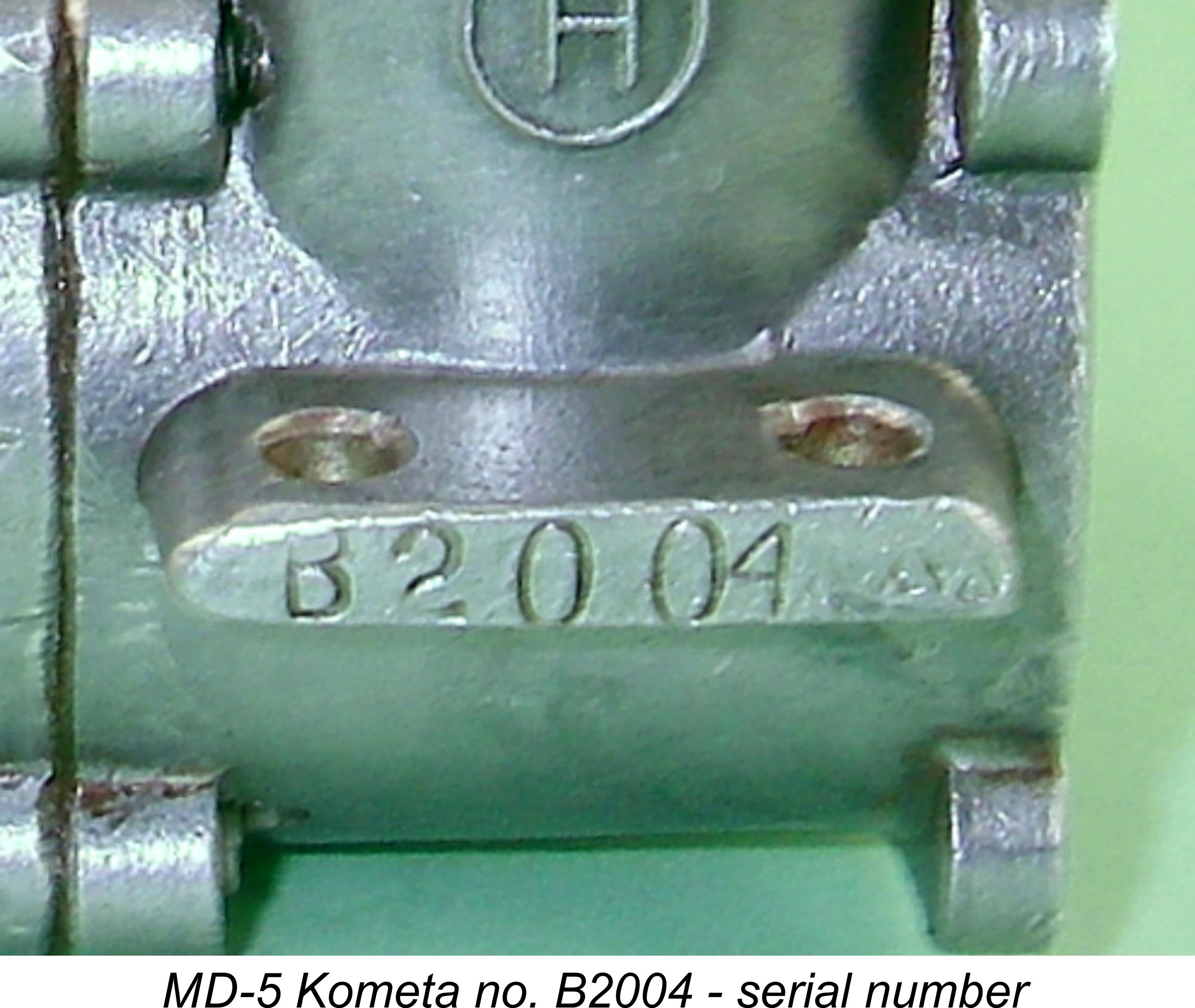 It’s unclear how many batches there actually were and how many engines were produced in each batch – only the analysis of a far greater body of data would settle this point. Moreover, there currently appears to be no way of dating these engines from their serial numbers. My own engine no. H774 seems to indicate that there were at least 15 batches before they stopped using serial numbers, since the letter H (pronounced “N”) is the fifteenth letter of the Russian alphabet. Some more serial numbers would really help to clarify this point ………….
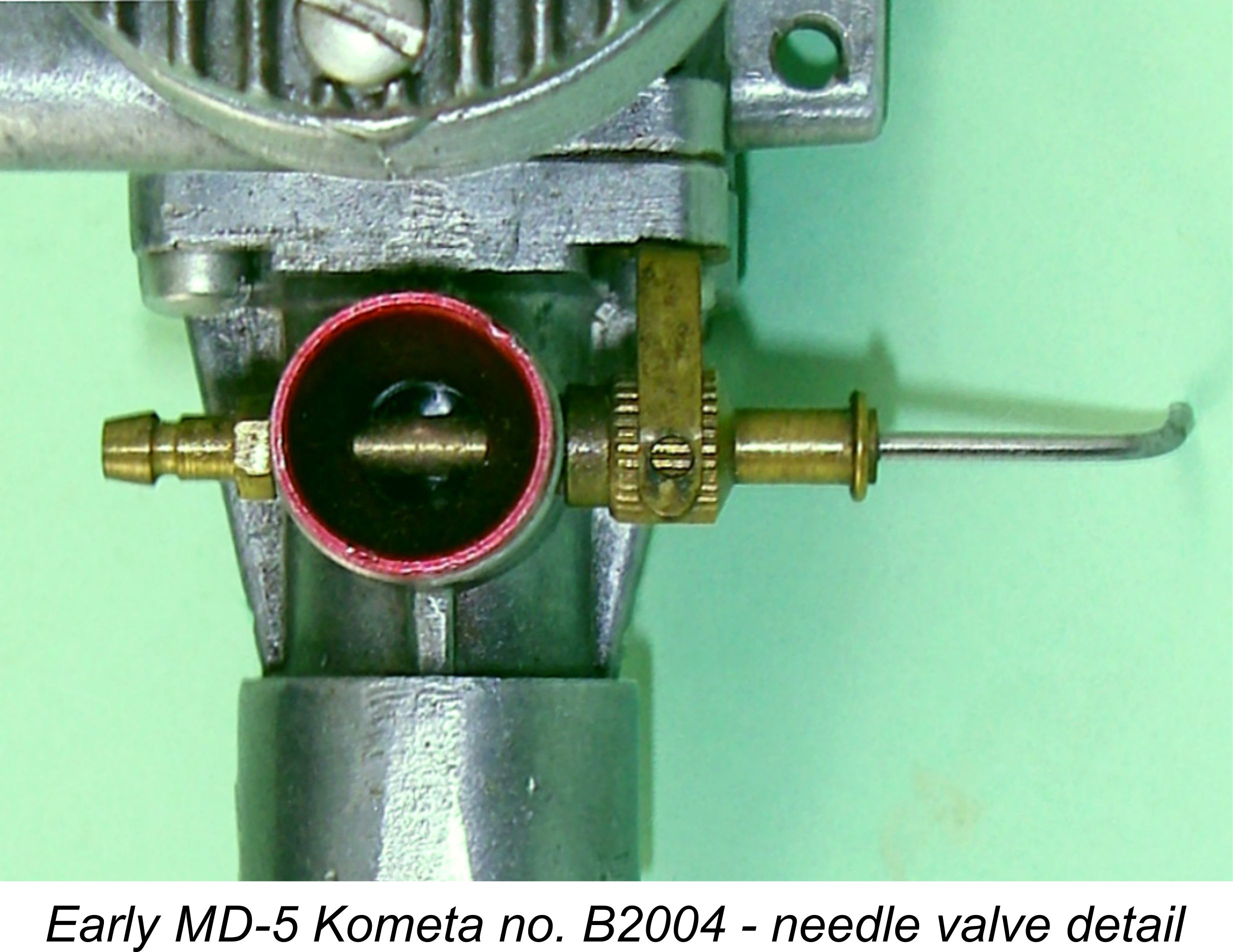 As already noted, the original examples of the MD-5 Kometa were essentially identical to their Super Tigre prototypes, even down to the needle valve assembly. This used an externally threaded spraybar of 3 mm nominal diameter with tension being provided by a leaf spring secured by one of the front housing screws and acting upon an internally-threaded knurled thimble mounted on the needle. Venturi throat diameter was 6 mm, in contrast to the 7 mm diameter used in the Super Tigre.
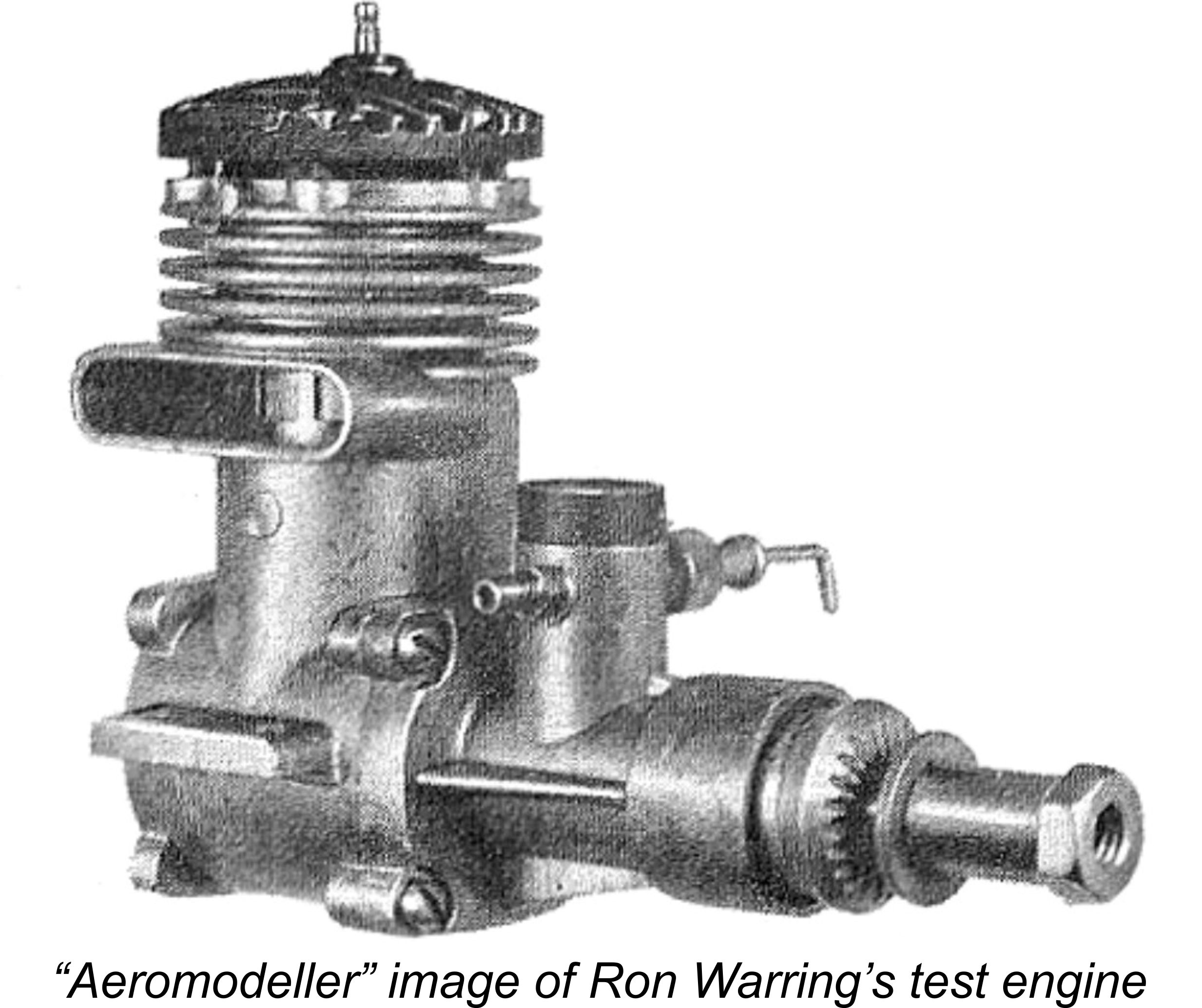
 As noted previously, these early examples bore serial numbers which were stamped onto the outer end of the left-hand mounting lug. The designation “Kometa / MД 5 “ appeared in Russian characters cast into the bypass side of the case, together with the Russian letter “H” (pronounced “N”) in a circle cast beneath the main designation. This letter appears to have been some kind of manufacturer’s trademark, since we’ve seen that it also appeared on the boxes in which the engines were supplied. At this stage, the backplate area of the crankcase was devoid of any form of script.
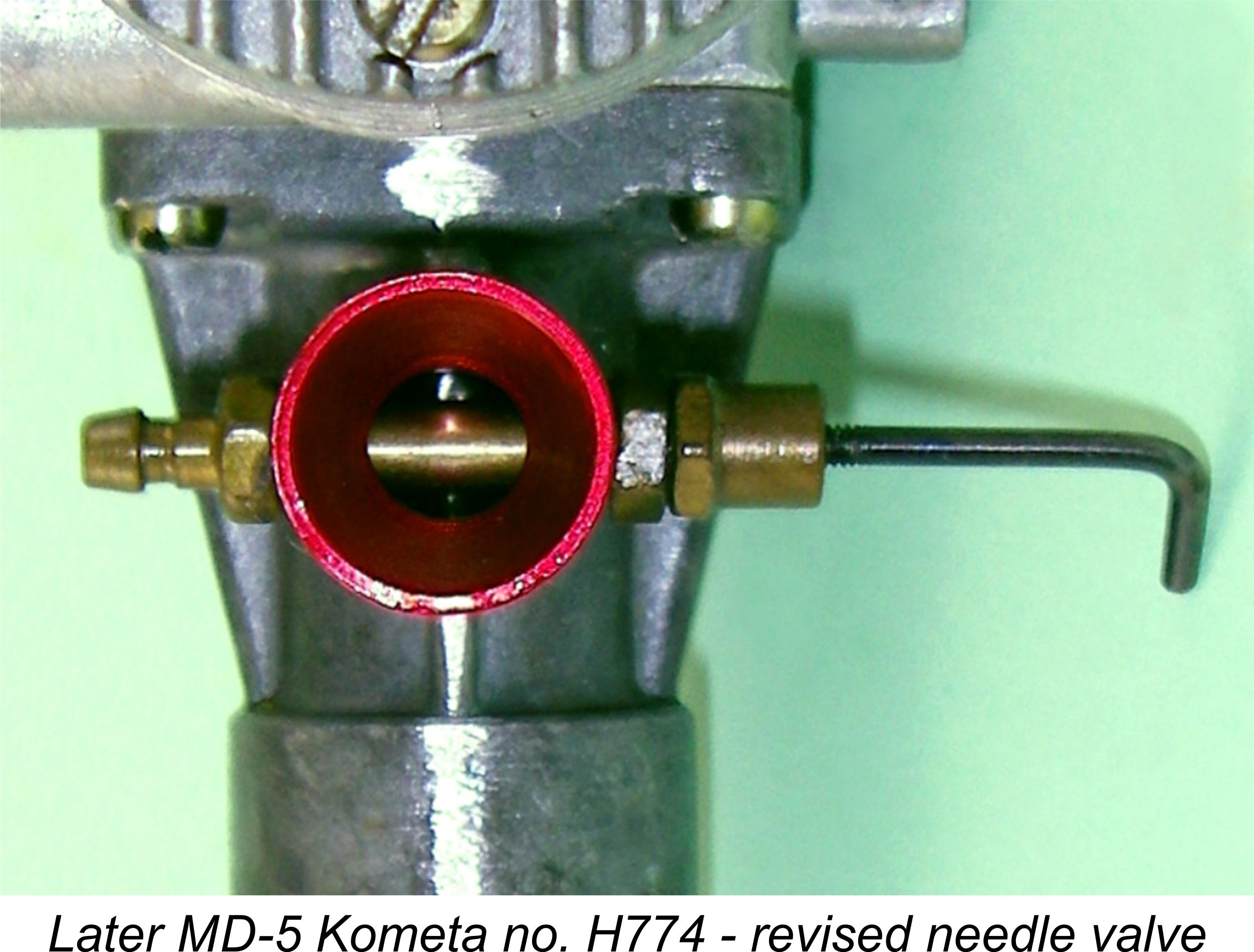 At some later point in time, the needle valve assembly was updated to conform to the revised Super Tigre arrangement using an internally threaded spraybar of 4 mm nominal diameter with an externally threaded plain needle and a gland nut for tension. Somewhat strangely, the 6 mm internal diameter of the venturi was
 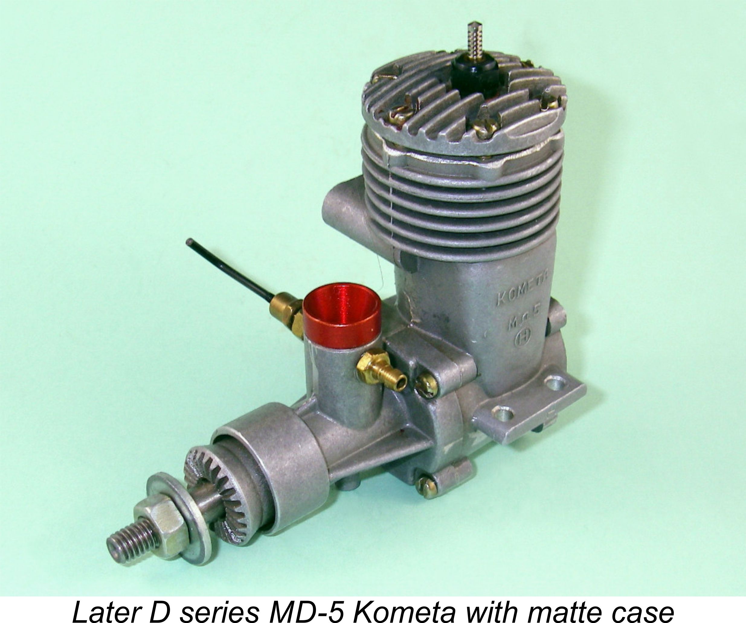 attractive matte exterior finish. These vapour-blasted cases bore the same model designation on the bypass side as had their predecessors. At around the same point in time, the engines ceased to display serial numbers, carrying only a letter indicating the series to which the engine belonged if they displayed any marking at all. The treatment of the conrod ends was also changed, the former lubrication slots being dropped in favour of simple holes drilled into the centre of the bearings. My illustrated example which displays the letter “D” as its Russian phonetic equivalent “Д” is of this type.
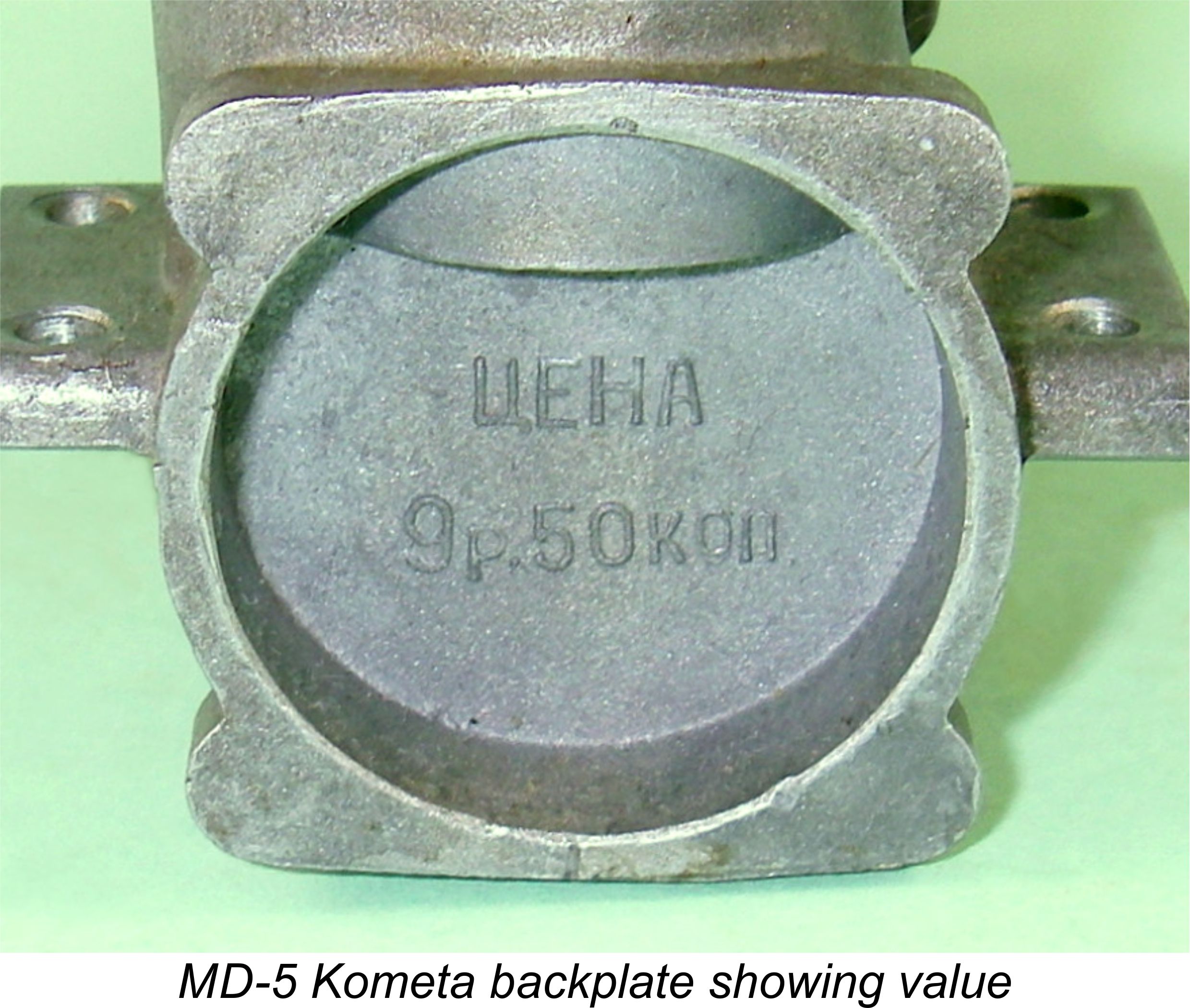 point, the backplate area began to display the Russian word for “value” (ЦЕНА) with a monetary amount cast in relief directly beneath it. The monetary amount must presumably be the value of either the engine or the casting. Now that’s commitment - I am not aware of another instance in which the value of an engine was cast into its crankcase!! This is doubtless a reflection of the then-prevailing Command Economy under which domestic prices were fixed, hence remaining predictably stable for lengthy periods.
 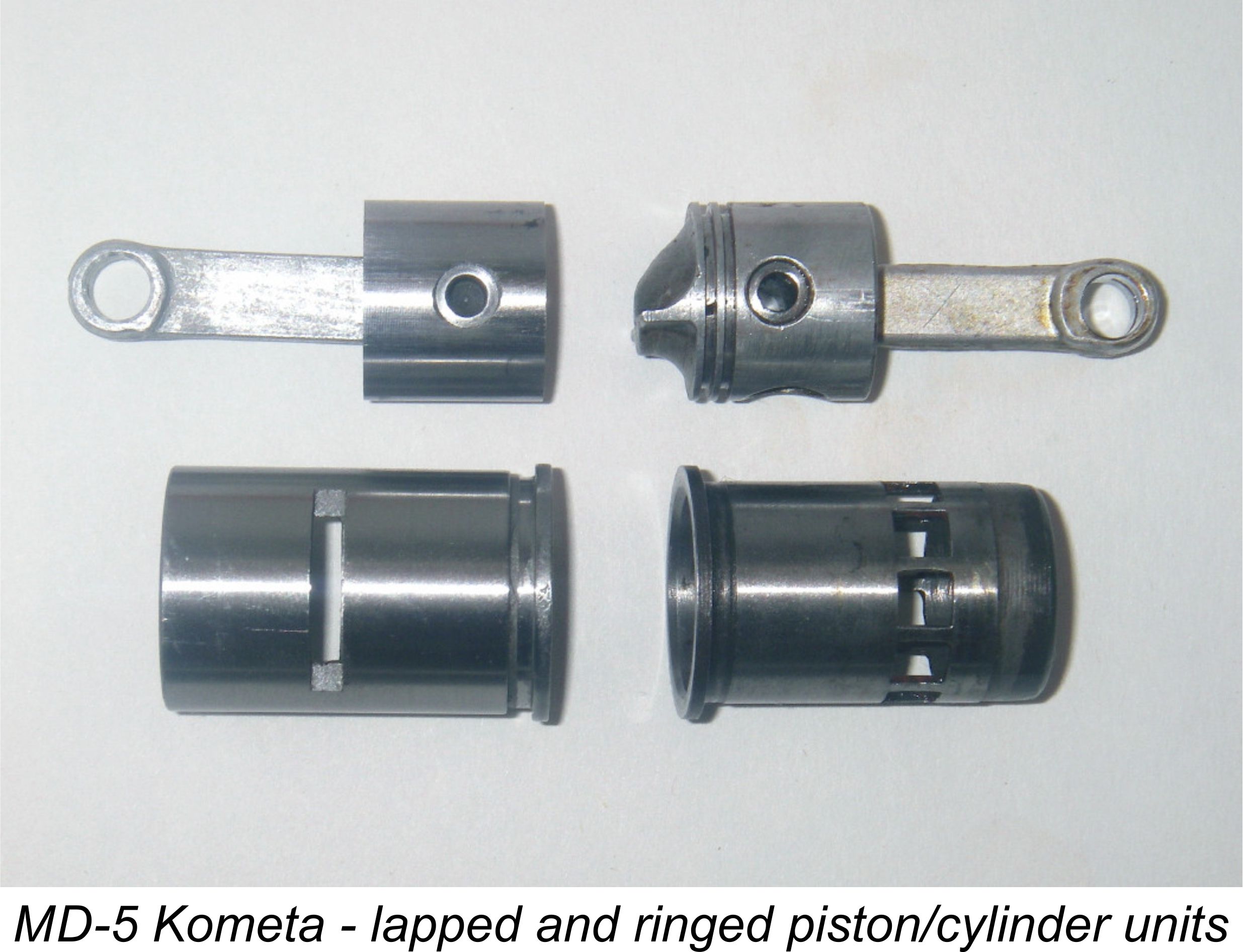 The final change of consequence was a switch from the ringed aluminium piston to a far heavier un-baffled flat-topped cast iron piston which was lapped into the steel liner and used in conjunction with an unfinned squish-bowl head with centrally-located plug. This change undoubtedly took place at some point prior to 1980, since I have a NIB “D” series example featuring the revised cylinder configuration which is clearly dated February 20th, 1980 on its papers.
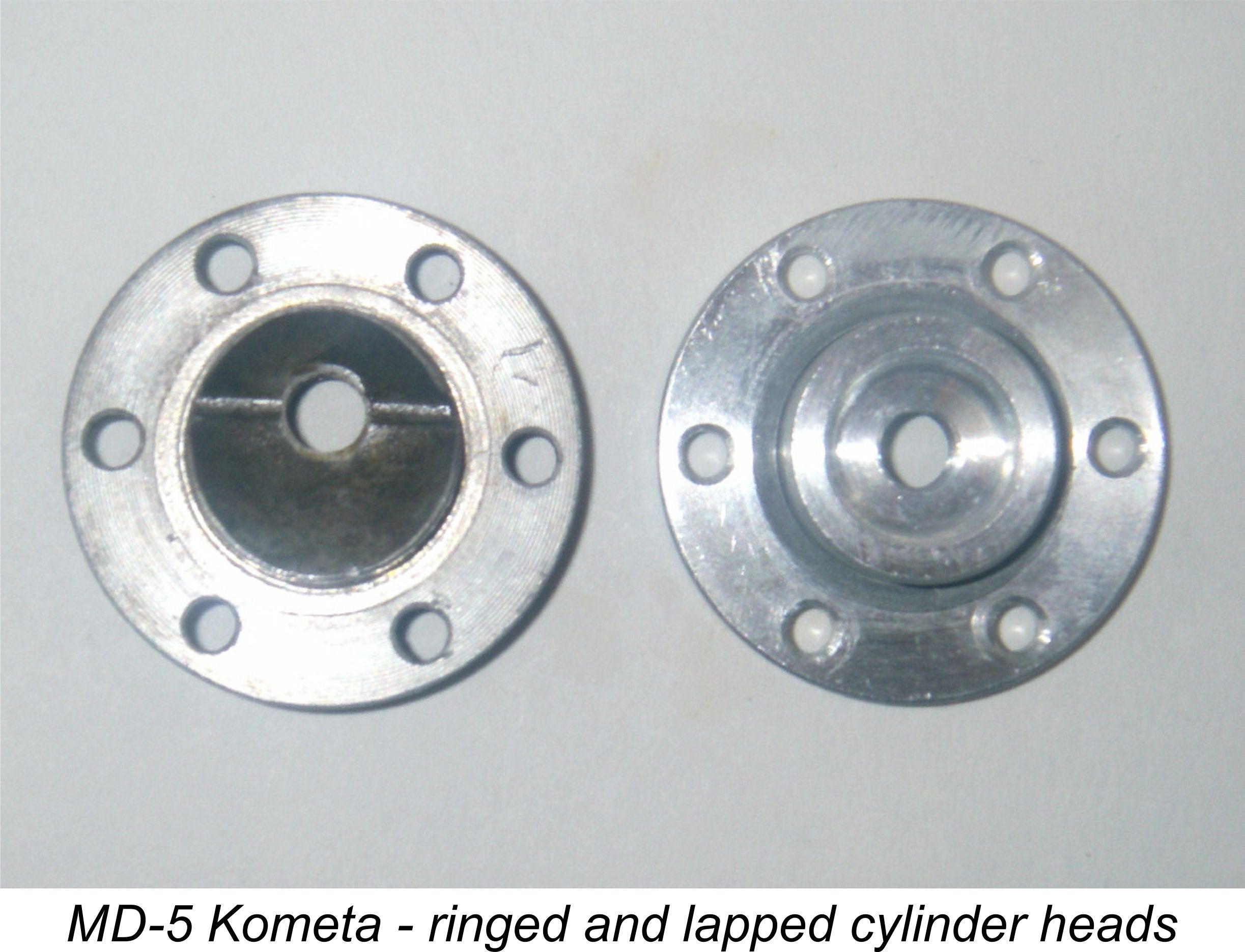 However, the introduction of the “E” series must have followed shortly thereafter, since I also have an E-series example of the Kometa which retains the ring piston. It would appear that the switch to the lapped piston more or less coincided with the change to the E series, with a few of the last D-series models receiving the revised components and the odd E-series example retaining the rings. Perhaps purchasers were offered the choice for a while.
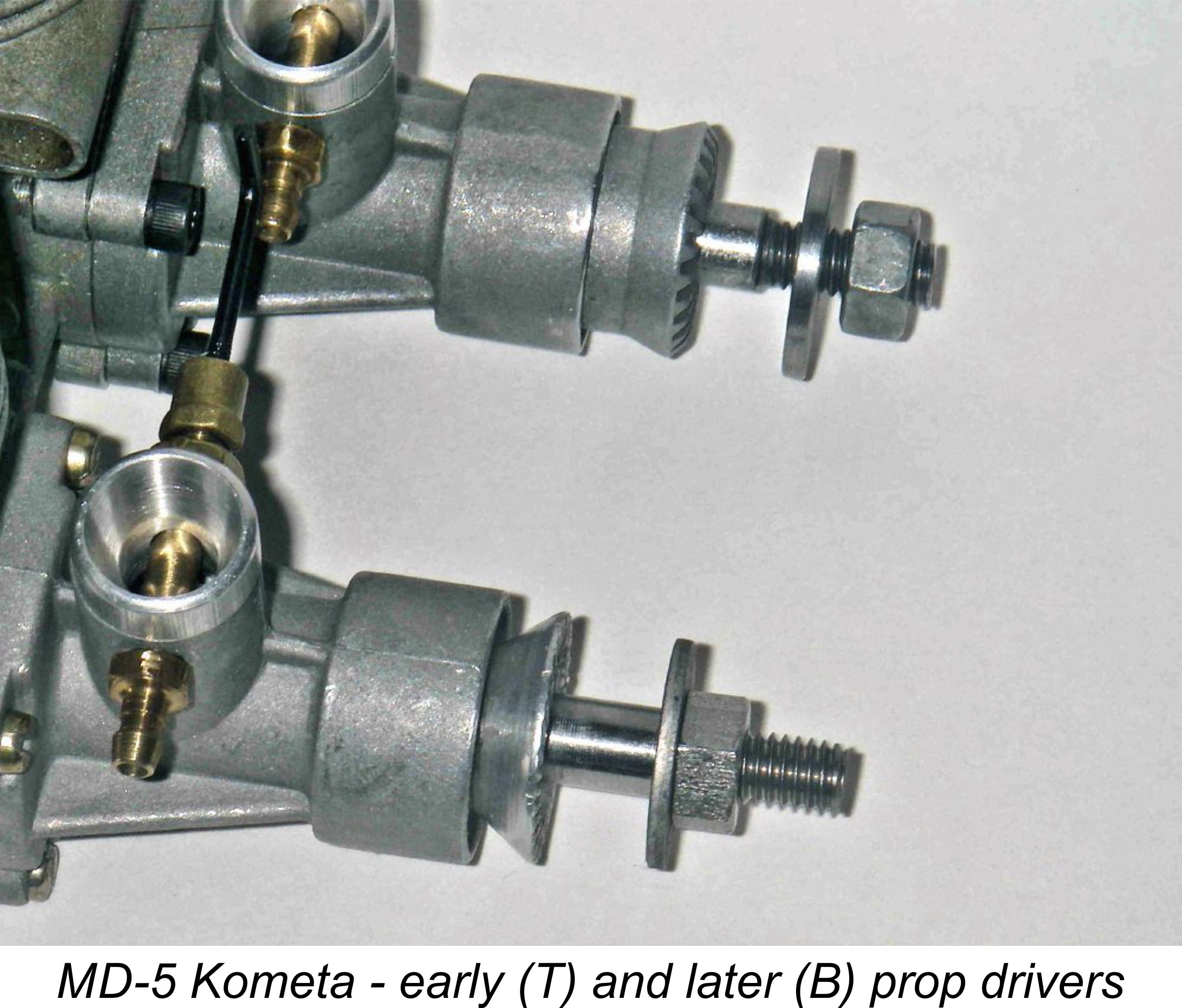 than being cast. My 1992 marine “E” series engine features this type of driver along with the lapped piston. In addition, some of the lapped piston models were converted to diesel operation, of which more below …………..
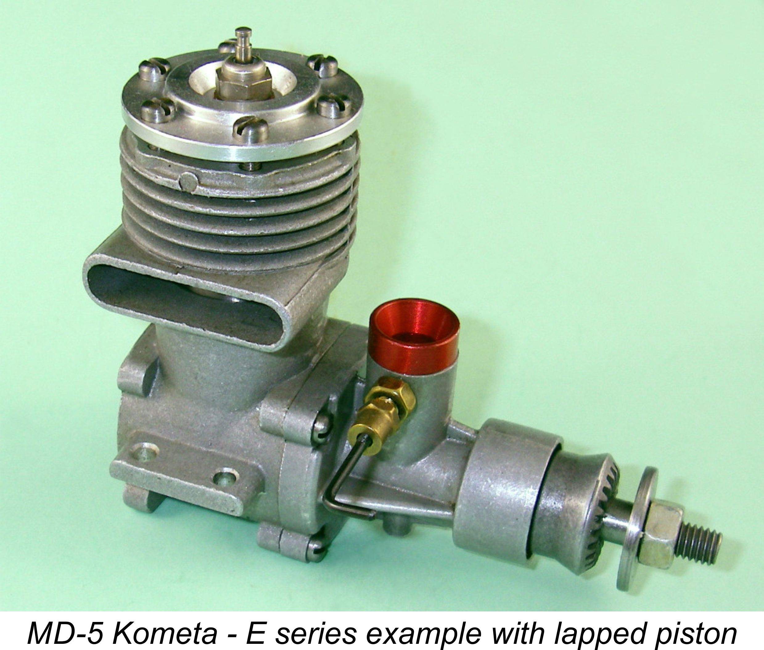
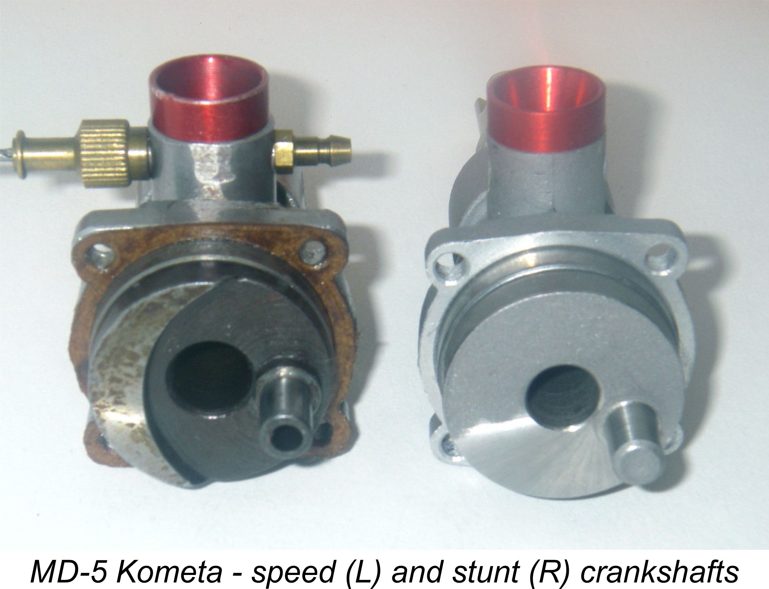 There was also a “stunt” crankshaft which, like the “stunt” liner, increasingly predominated over time, evidently becoming the standard fitting for the later models. This crankshaft did not feature any attempt at counterbalancing, the crank web being left in its plain disc configuration, presumably on the basis that in stunt service the engine would not be expected to rev nearly as high. In addition, the diameter of the internal gas passage inside the shaft was reduced from 9 mm to 8 mm.
 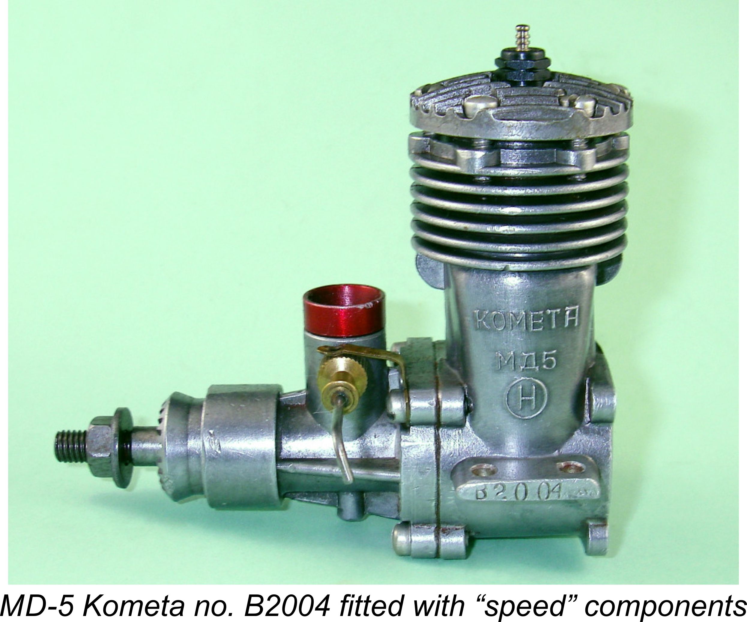 It seems to be beyond dispute that the makers envisioned the use of a far more open induction system for all-out contest work - a tapping point (un-drilled as supplied) was provided beneath the induction tube to provide for the use of crankshaft-timed tank pressurization from the crankcase. If such a system were used or a pen bladder set-up installed, the venturi insert could be greatly enlarged or even dispensed with altogether. In conjunction with the “speed” shaft and liner set-up, this would yield maximum power output for all-out competition.
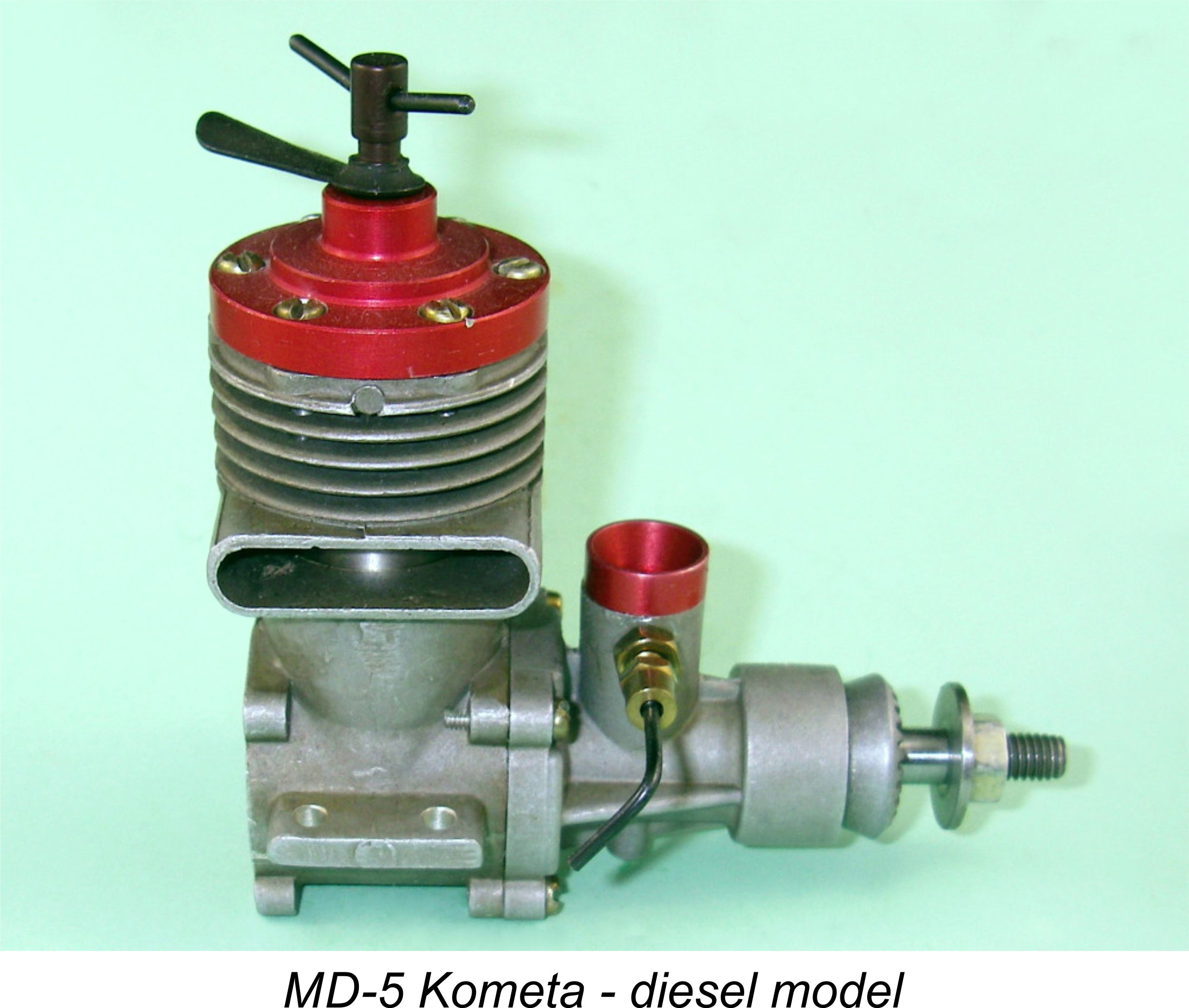 At some point following the introduction of the lapped piston version of the Kometa around 1980, a diesel version was introduced. It’s unclear when this occurred, but it seems likely that the diesel conversion was developed as a means of selling off surplus stocks of what had become a woefully outdated and hence uncompetitive glow-plug engine. This makes it appear likely that the diesel version appeared relatively late in the production life of the Kometa and that it represented the manufacturer’s final acceptance of the fact that the old Kometa glow-plug model had outlived its ability to compete in the marketplace.
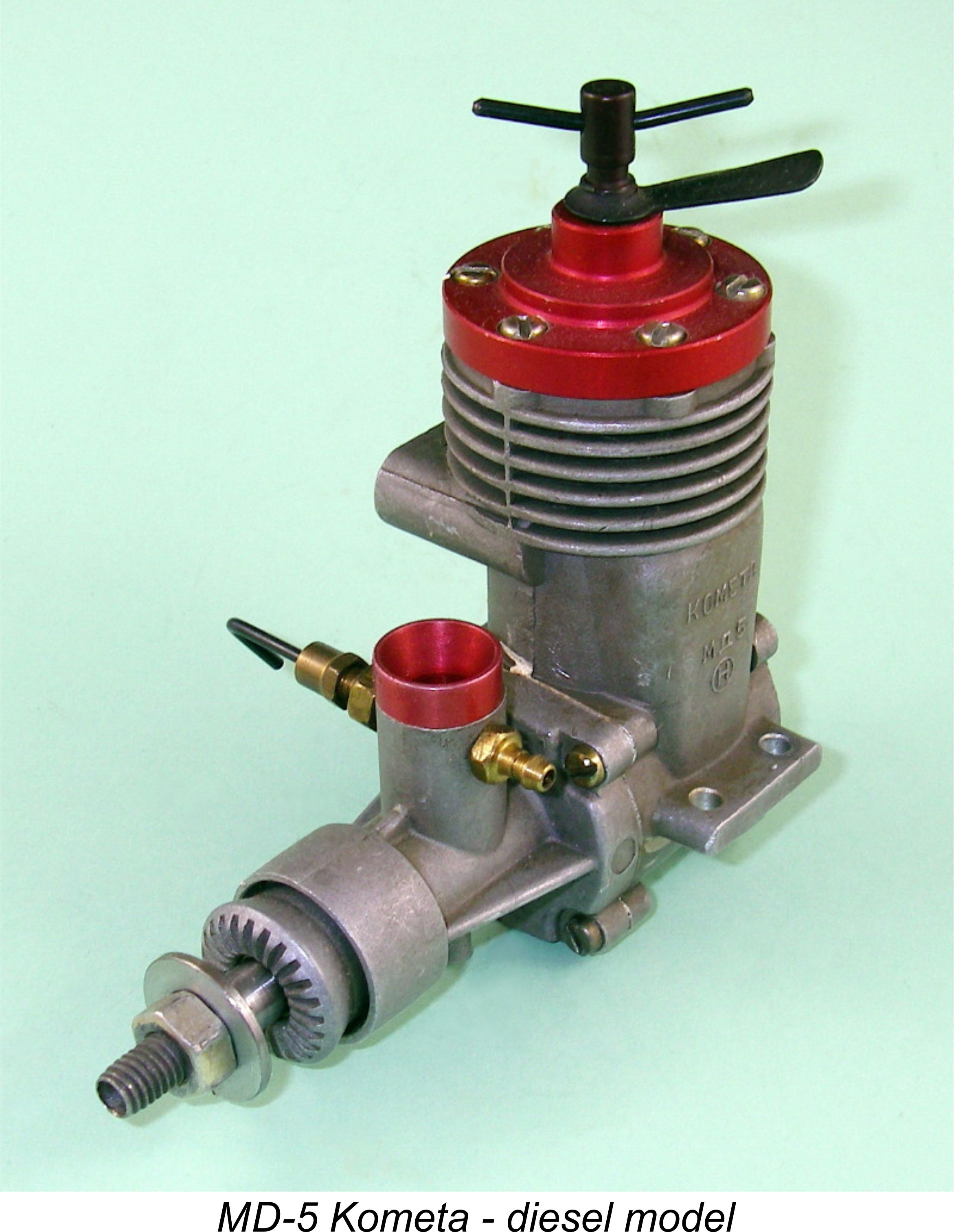
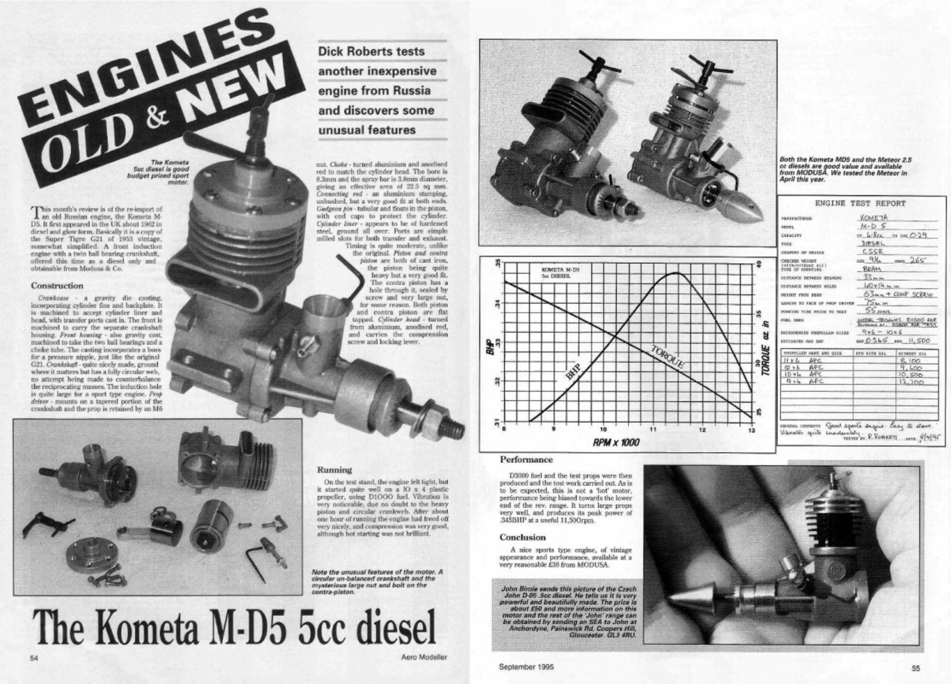
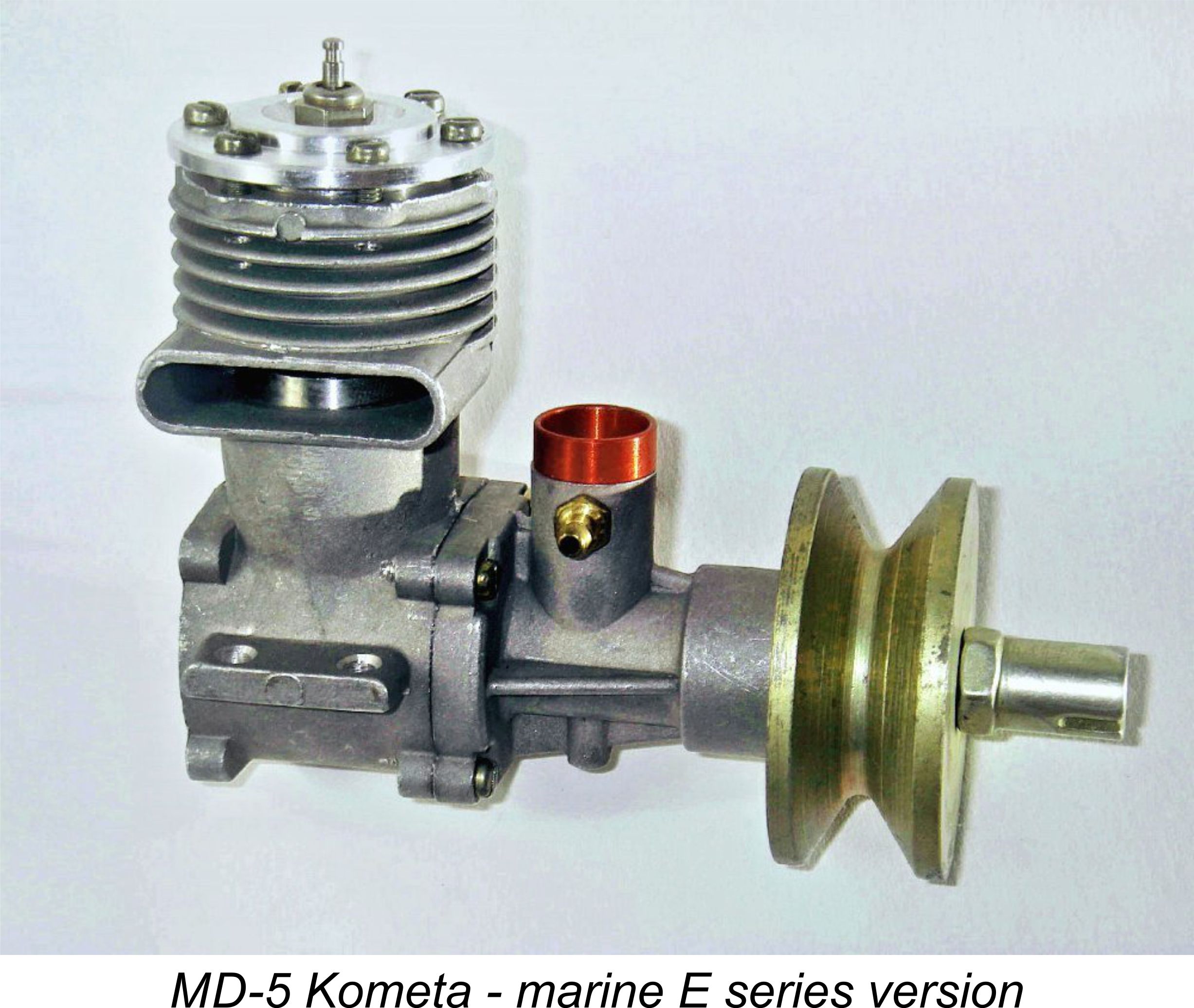
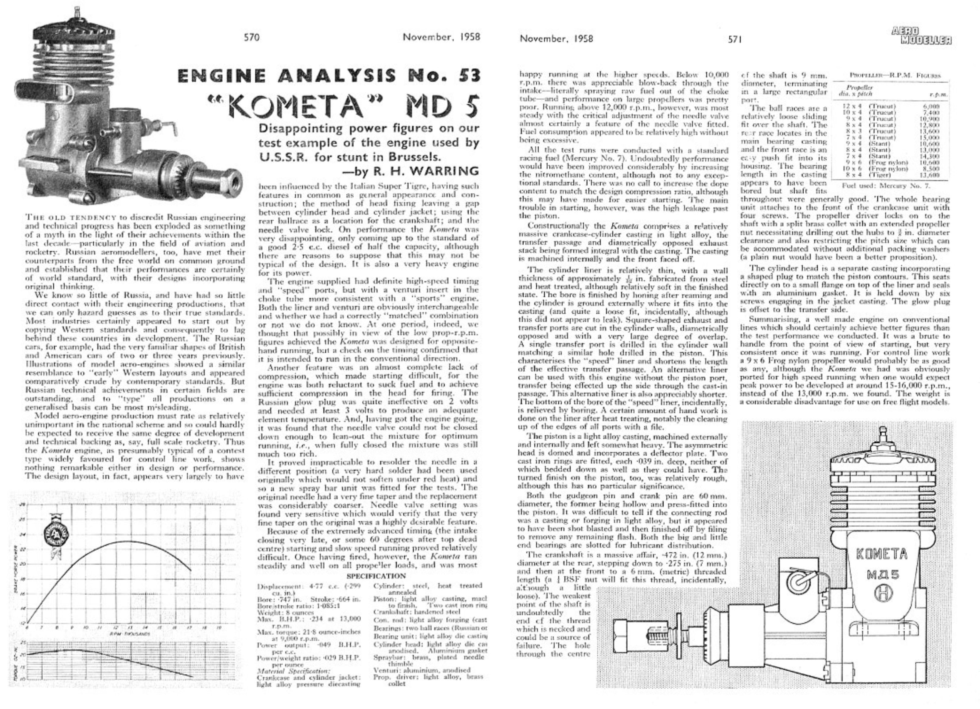 Overall, Warring characterized the results of this test as “disappointing”. He stated that the engine was “well made .....on conventional lines” and that it “should certainly achieve better figures than the test performance we conducted”.
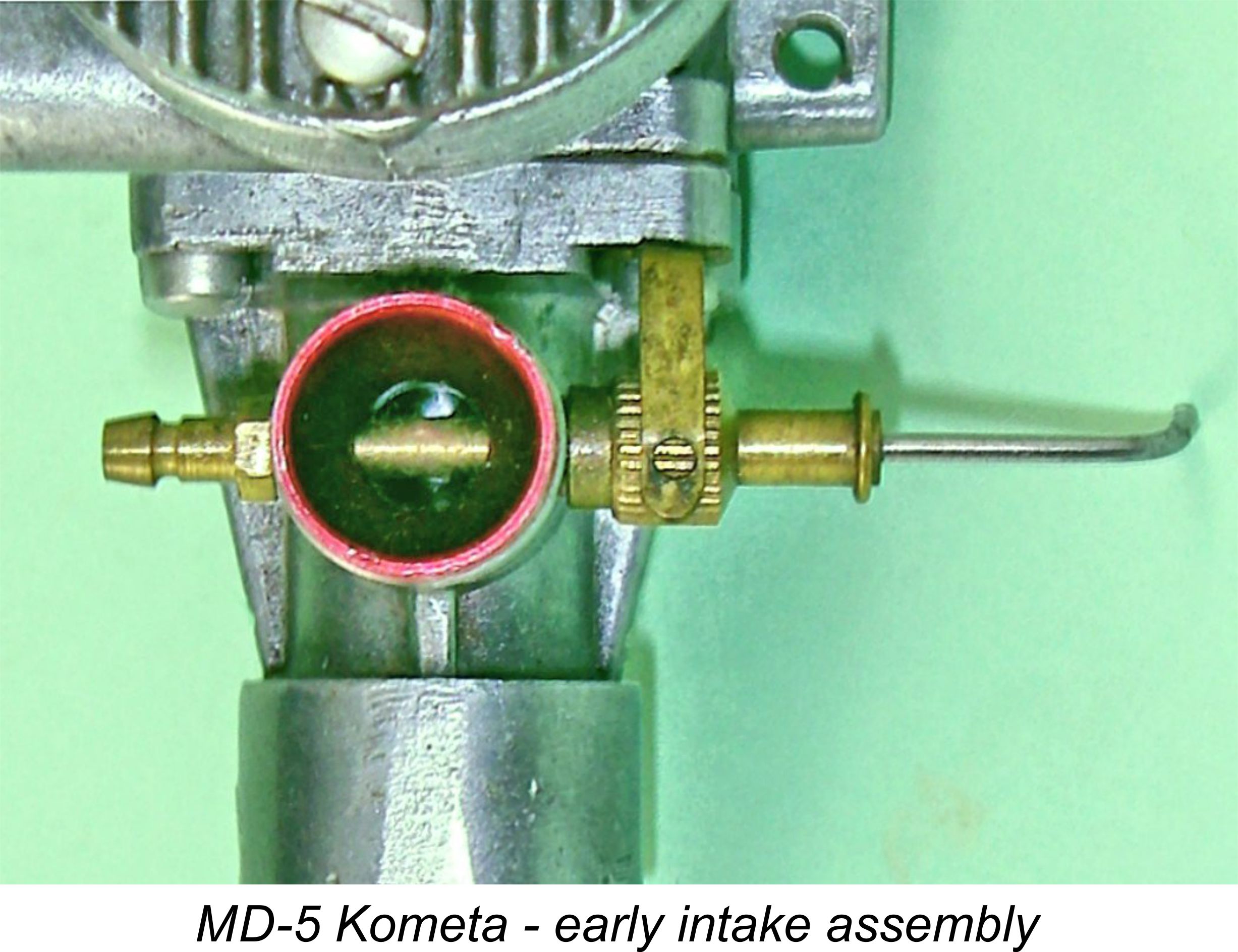
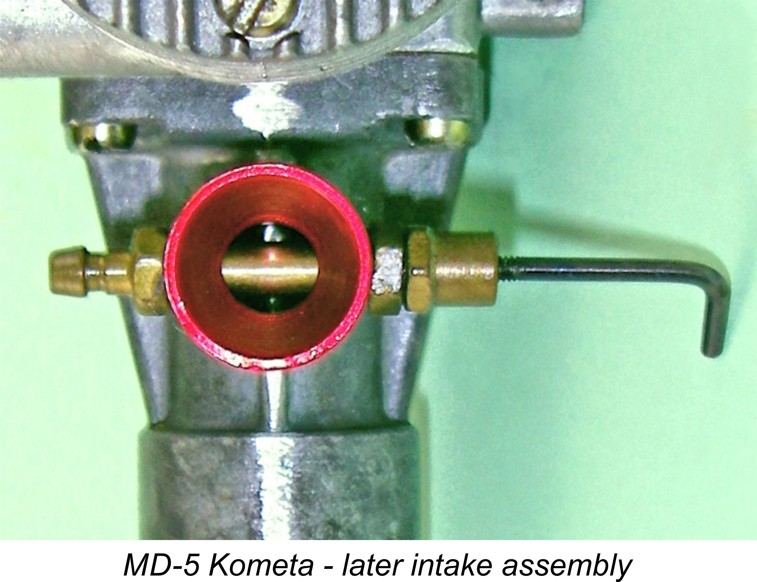
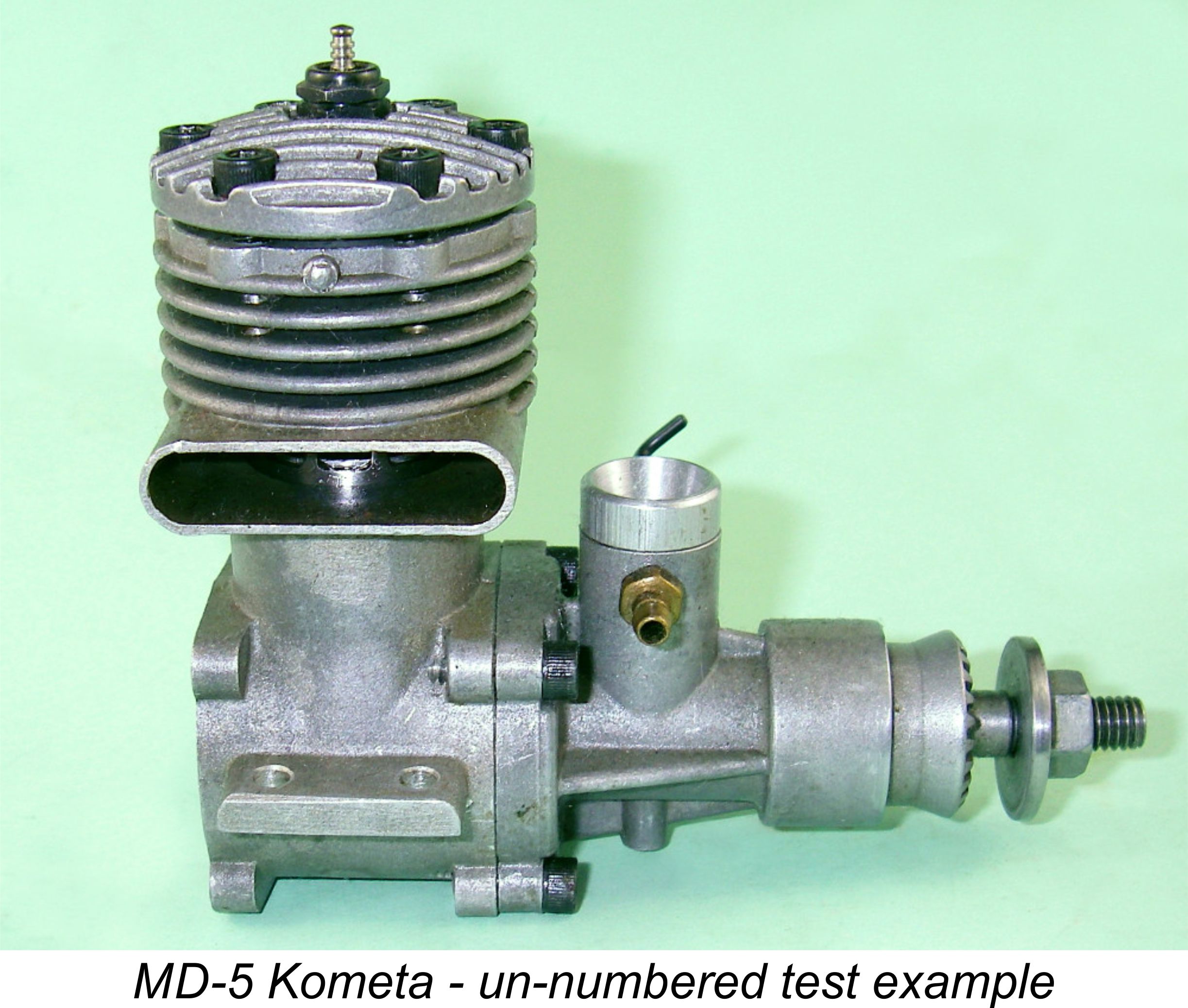 Looking over a few used examples of the Kometa in my possession, I came up with an un-numbered unit which was fitted with the “speed” liner and shaft. This particular example had done a fair bit of running both on the ground and in the air in my hands. It had the later 4 mm diameter spraybar fitted, prompting me to use a home-made 7 mm diameter venturi insert for my earlier stunt flying experiments using this motor.
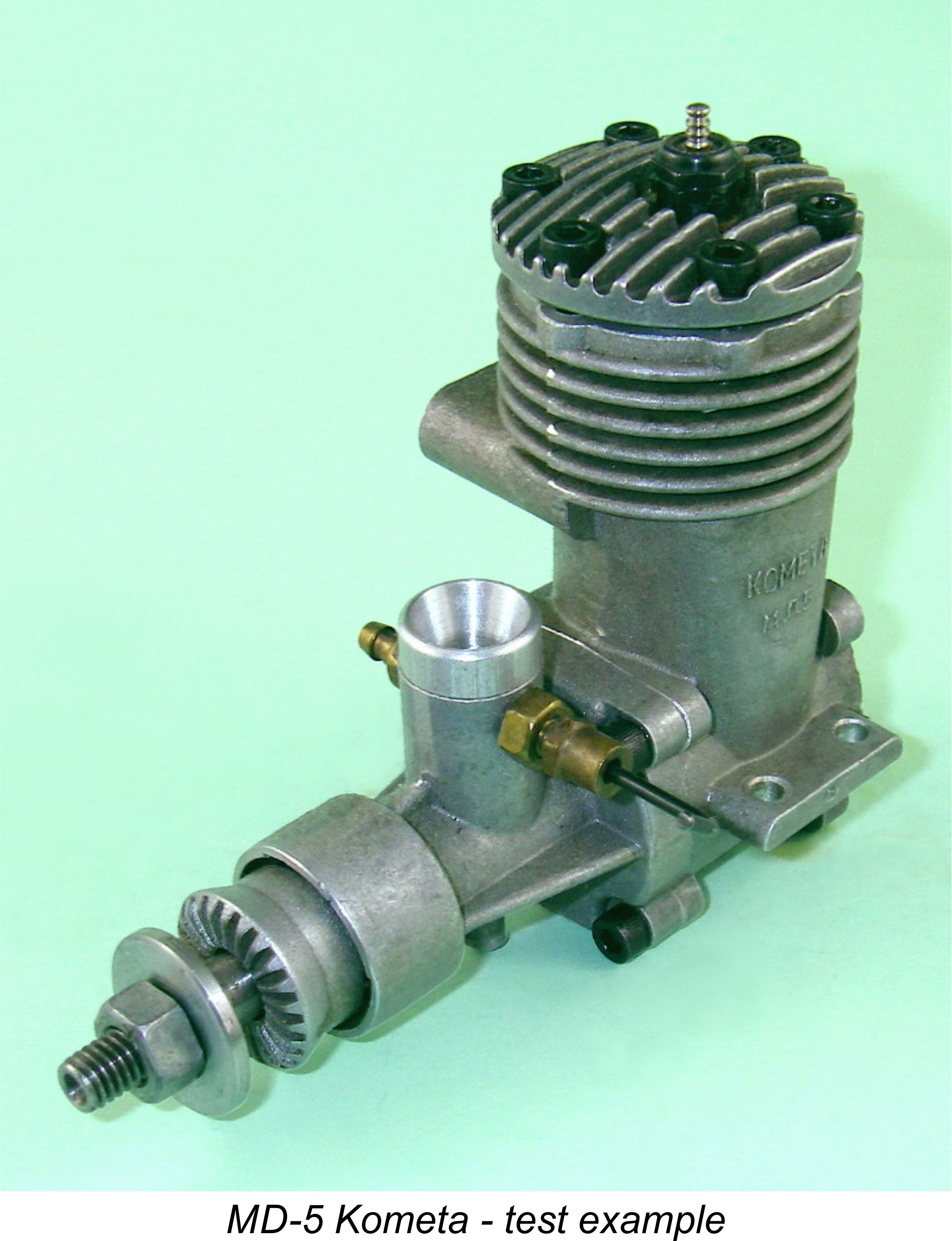
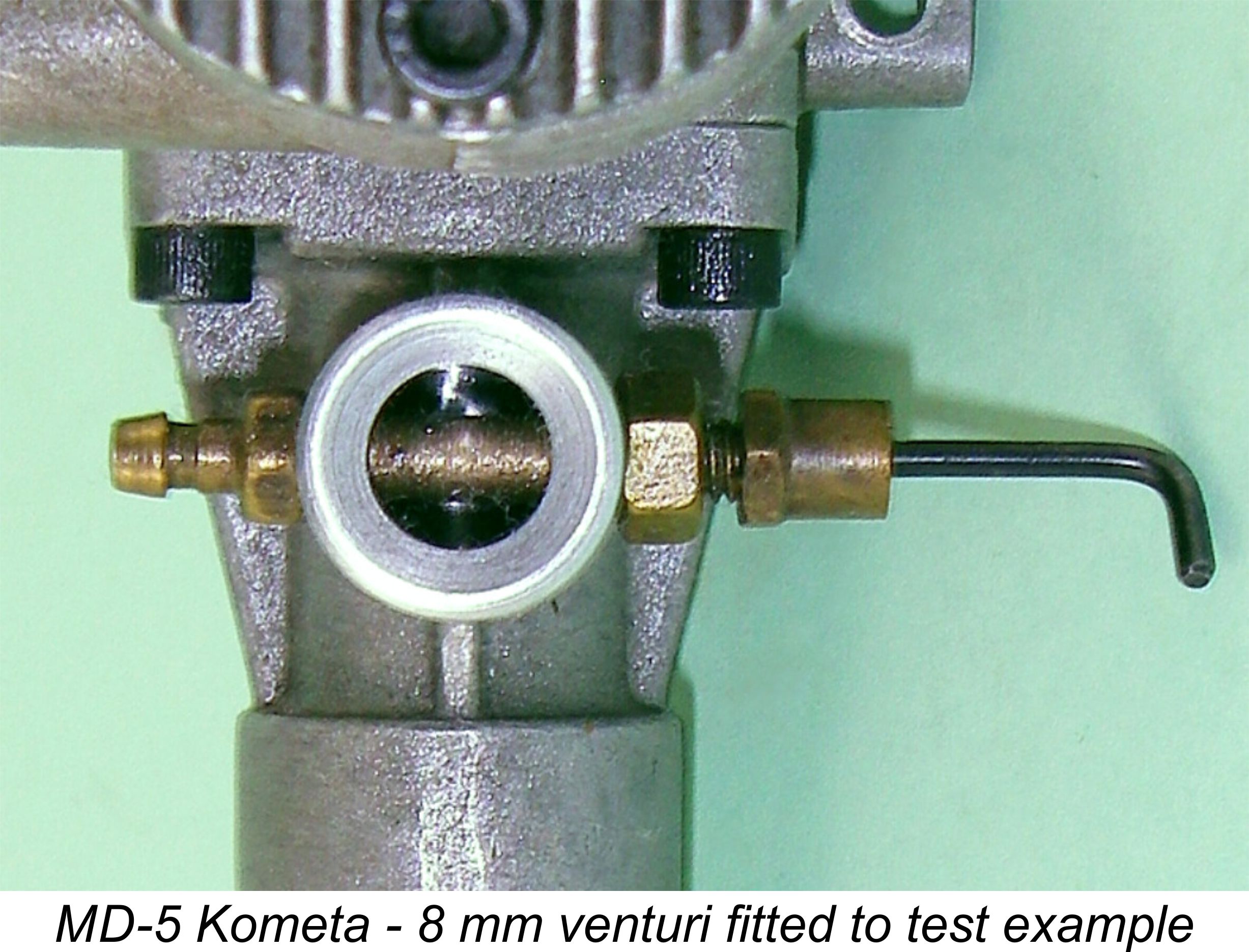 Upon further rational reflection, it was of course obvious that the above results could very well be the result of the engine being virtually choked to death by its own induction system. Deciding to bypass the 7 mm venturi that I had used for my stunt flying experiments, I dug in my “early Super Tigre” parts drawer and found an 8 mm I/D venturi from an original Super Tigre G21/29. This would increase throat area by some 78% - quite a change!
 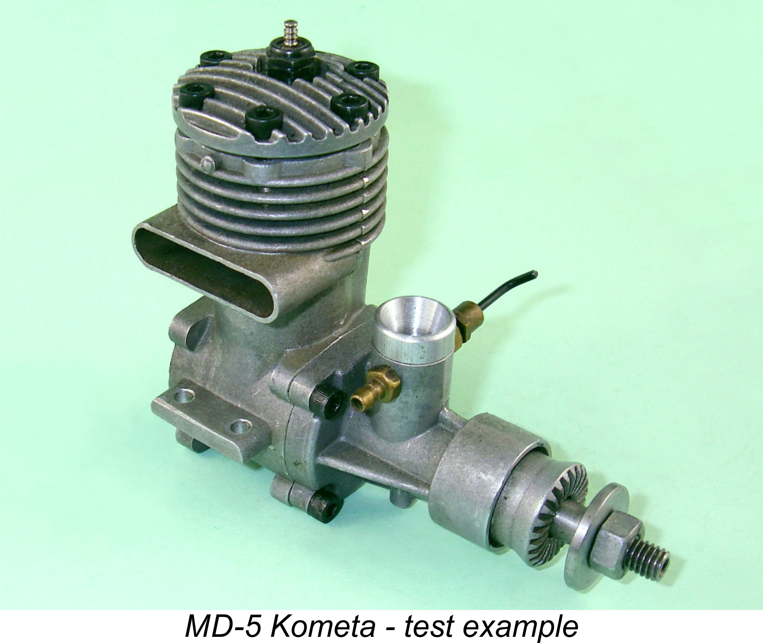 But there was even better news than this! Freed from the former constriction, the Kometa now got the Taipan 8x4 test prop up to a nice steady 15,400 rpm! This was using the same plug, fuel batch and prop as on the previous occasion, and the test location and conditions were identical. So the mere opening out of the venturi from 6 mm to 8 mm yielded an extra 2,200 rpm on this prop! The implied power output based on the estimated power absorption coefficient for this particular prop was 0.435 BHP. If ever there was an indication that this is a venturi-sensitive design, this was it!
 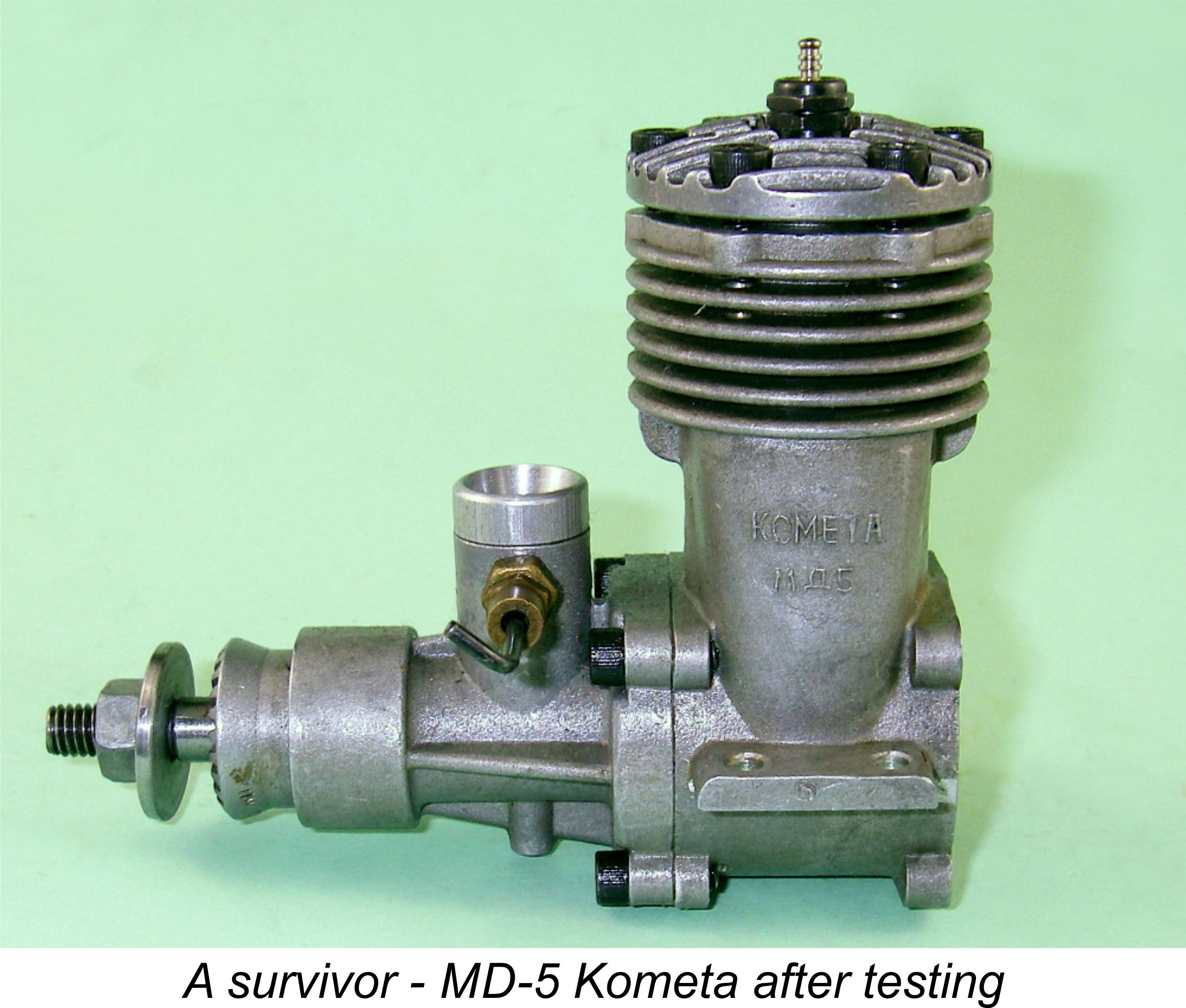 Of course, there was a downside. Suction with this venturi was right at the limit – any larger, and you’d need a pressure fuel system even on the bench. To get the engine to run rich for starting required that the needle be pulled out as far as it would go and remain in the threads. The level in the tank also had to be right up with the spraybar elevation. But once running, it was very easy to lean the engine out to obtain an optimum figure. In an actual model, the practical application of a venturi of this size would undoubtedly require the provision of some form of pressure feed.
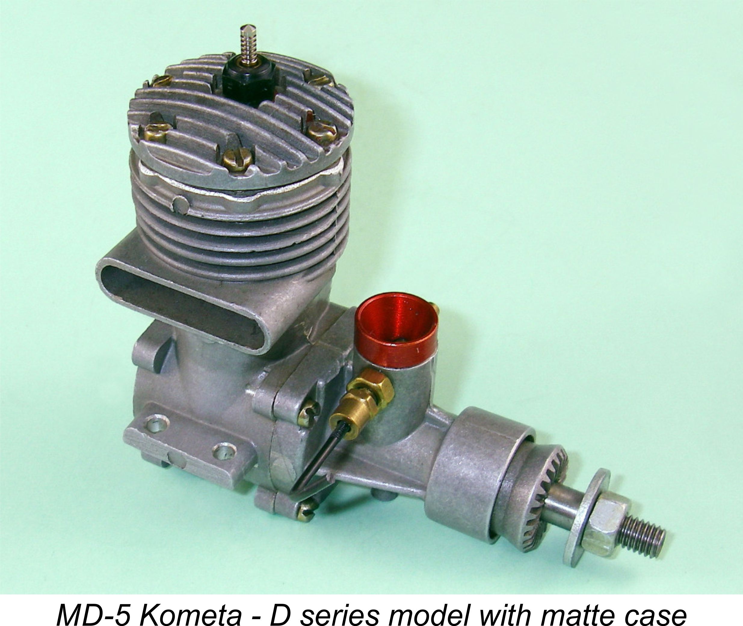 Well, the very high production figures achieved over the years coupled with the engine’s less-than-stellar reputation mean that new or near-new examples of this engine still appear regularly at reasonable cost on eBay and elsewhere. Accordingly, there’s every expectation that anyone wanting a nice old classic glow-plug engine with an interesting pedigree for nostalgia flying could find an affordable example. Original Super Tigres are far less common and a lot more expensive, so here’s one answer – go clone!! But there are a few words of advice for would-be users:
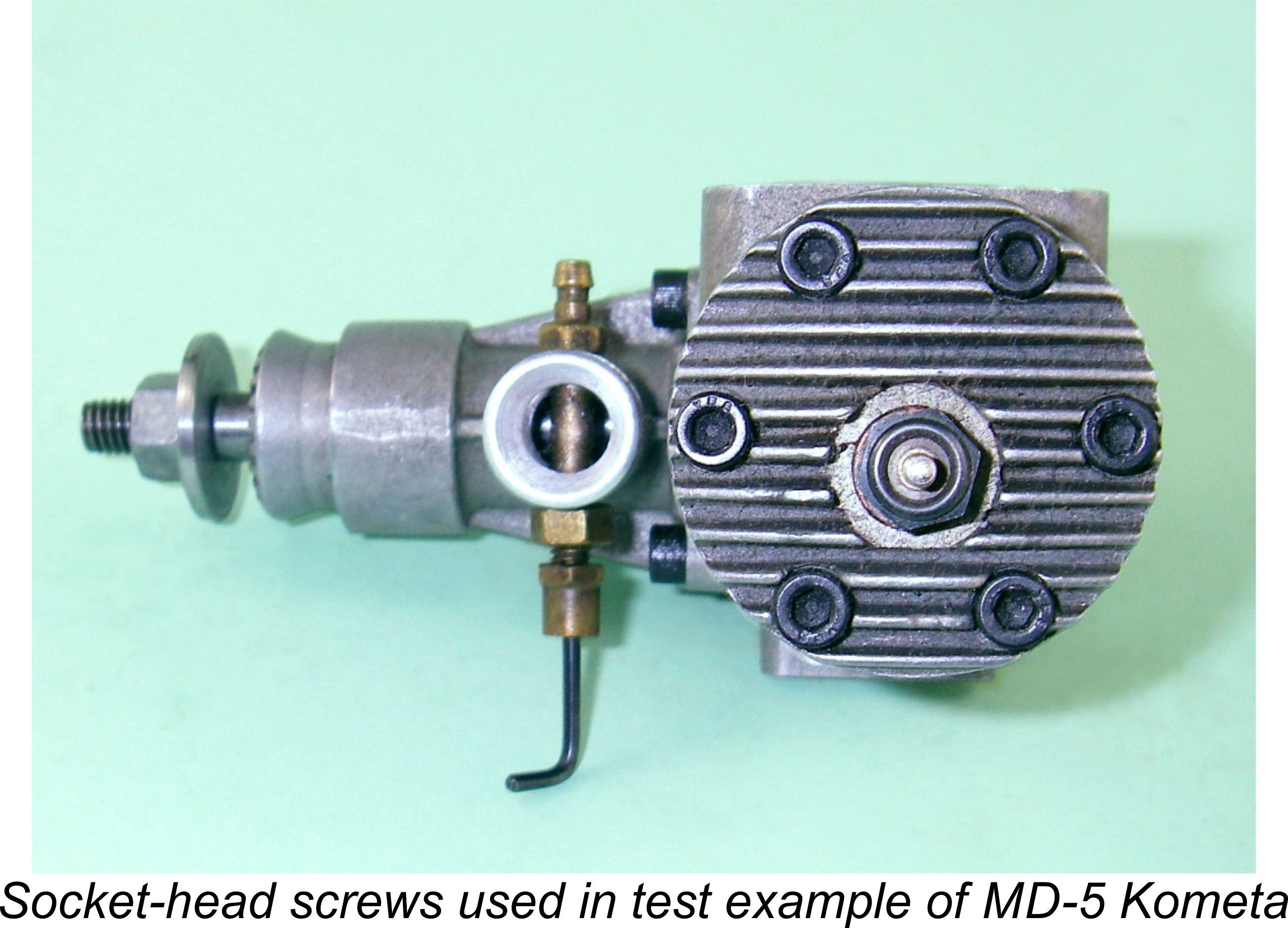 Replace the stock 3 mm assembly screws with quality Allen-head items. The Russian slot-head screws supplied with the engine are junk – they’re poorly threaded, too soft and too short, consequently tending to cause stripped threads in the casting. Make sure that the screws that you use are of the correct length or are adjusted for length to utilize all of the available thread in the tapped holes in the casting – the thread lengths provided are a bit marginal and should be fully exploited to minimize the possibility of stripping a thread. For conservation reasons, I recommend that you preserve the original screws so that the engine can be restored to its original state if desired for “collector” purposes.
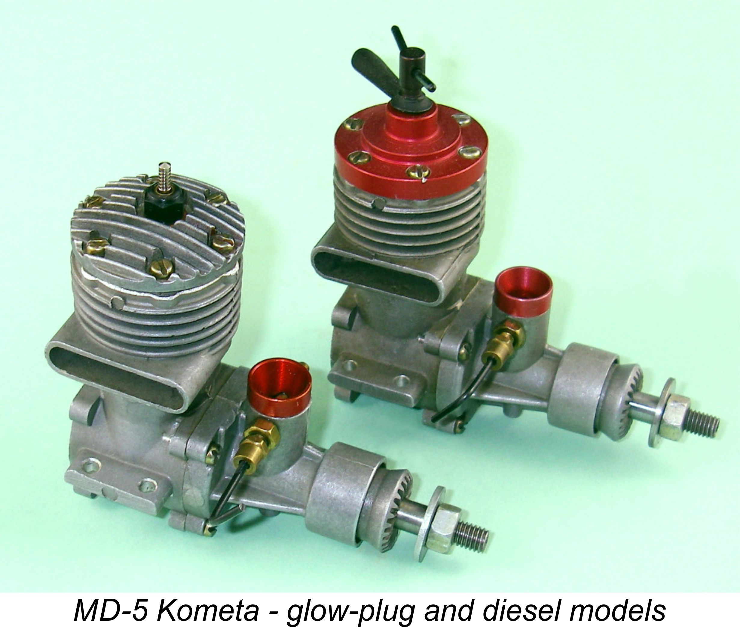 If there are any villains in this story, they are the Russian manufacturers, who initially fell short of providing adequate quality control in certain areas and then compounded this omission by sending these engines out equipped for operation in applications to which they were quite unsuited. Because the engine was at heart a high speed “racing” engine, any application in another field of modelling represented a squandering of its true capabilities. It was clearly a perfectly satisfactory unit for applications requiring a strong top end, and its use should have been restricted to those applications. There were doubtless far better engines for the other uses to which the makers appear to have envisioned the Kometa being put.
| |