
|
|
Aptly-Named Classic: The Zeiss Pioneer 1 "U-Boat" Diesel
This highly unusual and hence very interesting engine is little-known outside of its native Germany, due in large part to the fact that it was manufactured for a relatively short period around 1950-1952 in what was then East Germany. At the time in question, East Germany was very much a bulwark of the Communist bloc lying behind the impenetrable barrier of the Iron Curtain. As a result, information regarding East German model engine production in the early post-war period was scanty in the extreme, hence going largely unreported in the English-language modelling media. By the mid 1950's, when model engine manufacturing activities in Iron Curtain countries began to come under regular scrutiny from elsewhere, the "U-Boat" had submerged without trace (pun intended!). However, its manufacturers were by no means unknown in the West! In fact, the Carl Zeiss company was one of the longest-established and most highly respected industrial enterprises in Europe at the time when it first entered the model engine business, albeit having built up its reputation in a totally unrelated field. The The Zeiss Pioneer was previously the subject of a November 2013 article which may still be accessed on the late Ron Chernich’s wonderful “Model Engine News” (MEN) web site. The re-publication of this article on my own website was made necessary by the fact that my mate Ron unfortunately left us in 2014 without sharing the required access codes for his heavily encrypted site. This has resulted in that site becoming frozen, with no maintenance being possible. I was unwilling to risk the loss of this material as Ron’s un-maintained site deteriorates, hence its re-publication here. In undertaking the task of documenting this rare engine, I openly recognize that I am doubtless woefully under-qualified to do so! Apart from my sincere interest in the Jena engines, my sole credential is the fact that I own a number of Zeiss Jena models, including a fine example of the Pioneer which is thus available for direct examination. There can be no doubt that many model engine aficionados living in Germany know far more about the I've done my best to ensure that the information set out herein is accurate as far as it goes. No doubt there's much more, and it's my earnest hope that some English-speaking German reader will be inspired to contact me to fill in the many gaps and inaccuracies which undoubtedly remain in what follows. All contributions gratefully and openly acknowledged! A great deal of information regarding the Zeiss engines produced at Jena is apparently contained in a 2007 self-published book by Eberhard Stenzel entitled "Selbstzuenderkleinstmotoren und Gluehzuenderkleinstmotoren aus Jena" (Self-ignition Model Engines and Glow-ignition Model Engines from Jena, perhaps better translated as "Diesel and Glow-plug Model Engines from Jena"). Apparently, this book is only available in German. Moreover, it doesn't seem to be readily accessible even in that language - to this point, I have been unable to obtain a copy for reference. If any kind German reader can assist in this regard, please get in touch! Ich kann Deutsch lesen (aber sehr langsam)! Now, before we turn our attention to the engine itself, it seems appropriate that we should spend some time reviewing the history of its manufacturer. Accordingly, I’ll begin as usual with some background. Background
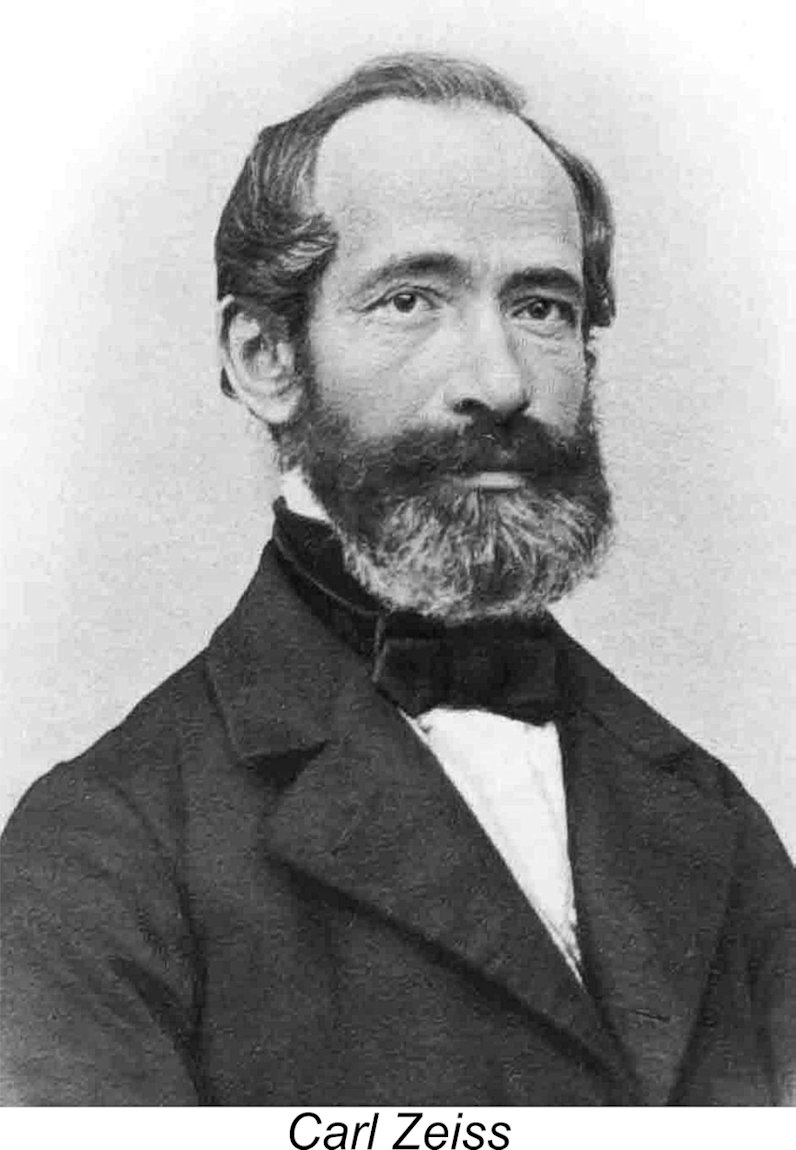
The company was founded in 1846 by 30-year-old Carl Friedrich Zeiss (1816 - 1888), a trained optician by profession. Zeiss lived and worked in Jena, a university town of modest size in what was later to become East Germany. At the time when Carl Zeiss established his business, Germany had yet to become a unified nation. Consequently, Jena was then part of the Grand Duchy of Saxe-Weimar-Eisenach, which only became part of the German Empire in 1871. With a number of structural reorganizations and name changes, the company has traded continuously ever since - a corporate lifespan of 178 years and counting (in 2024). The initial operations of the fledgling company were carried on from a small optical workshop in Jena staffed by Carl Zeiss himself working alone. At the outset, this facility was dedicated full-time to the manufacture of The University of Jena soon became a major customer, a connection through which Zeiss's reputation as a quality instrument maker quickly spread far and wide. Naturally, this greatly increased the demand for his instruments. By 1861 Zeiss had 20 or more people working under him and was considered to be among the best scientific instrument-makers in Germany, winning a Gold Medal at that year's Thuringian Industrial Exhibition. This success resulted in the further rapid growth of the business, to the point where another move to larger premises was found necessary in 1864. By 1866 the expanded Zeiss company had sold its 1,000th microscope, with demand still rising steadily. The company soon found itself employing over 200 people.
These three figures continued to work together to build the company up into one of the world's leading manufacturers of optical systems. They maintained an entirely separate Carl Zeiss lived to see his company sell its 10,000th microscope, but died soon thereafter in 1888 at the age of 72. His senior partner Ernst Abbe continued to lead the company forward, in cooperation with Otto Schott. One of Abbe's first actions was to establish the Carl-Zeiss-Stiftung (Carl Zeiss Foundation) to oversee the operations of the various Zeiss companies. The mission of the Foundation was to ensure that these operations remained consistent with the strongly-held social visions of the companies' founders. Any profits over and above those necessary for the growth and stability of the firms were diverted to the Foundation to be used to finance a range of scientific research, cultural and employee benefit programs. The world would be a far better place if more of today's major companies adopted similar principles.............. The company displayed a high level of concern for the well-being of its employees, as reflected in its many innovative employee benefit programs. As might be expected, this resulted in an unusually high level of employee loyalty and dedication. As always in such cases, the company's attitude was amply repaid through the consistently high standard of workmanship and quality control embodied in Zeiss products as a result of the dedication of its staff. Too bad that more of today’s bean-counting company owners/managers seem unable to learn from such examples……………….
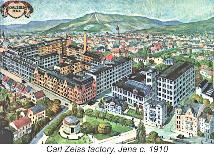
The company survived the WW1 years and continued its successful operation thereafter. In 1928 Carl Zeiss acquired Hensoldt AG, which later took over production of certain Zeiss products such as binoculars and riflescopes. The term AG stands for Aktiengesellschaft, which is roughly equivalent to today's English Plc or Public Limited Company. A reasonable translation would be the Hensoldt Corporation. This merger of the two companies led to the periodic appearance of certain Zeiss products under both the Hensoldt and Zeiss brand names. The company's Hensoldt System Technology division (resulting from a merger of the military optics operations of Leica and Hensoldt) was actually continued by Zeiss under the Hensoldt name until 2006.
The onset of WW2 brought less happy times to Zeiss. The progressive drafting of a major proportion of the German male population into the military soon left Zeiss in a situation where they faced a severe shortfall in the skilled labour force required to continue their operations. To exacerbate this challenge, their products were in great demand for military purposes, dictating that full production be maintained. To meet this challenge, the Zeiss company participated in Nazi Germany's Zwangsarbeiter (Forced Labour) program, using forced labour extensively during the wartime period. Although management undoubtedly made full use of the program, it seems doubtful that they did so with any great enthusiasm - such a program was very far removed from the high social ideals of the company's founders which had hitherto guided its operations. Moreover, the employee dedication from which the company had benefited previously was completely lost once forced labour came to the fore, which doubtless had an adverse effect upon the quality of the company's products as well as its production efficiency. It seems likely that the company saw participation in this program as their only means of staying in business given that many of their skilled pre-war employees were now otherwise engaged. No excuse whatsoever for the highly abusive and indeed essentially criminal nature of the forced labour system, of course - merely an explanation of sorts.
Before the war, the Zeiss company had achieved considerable sales success in other countries such as the United States. The very high international reputation which Zeiss had established between the wars is reflected in the fact that when America entered the conflict in late 1941 the US military actually instigated a targeted program under which private citizens were specifically encouraged to turn in their Zeiss binoculars for use by the military. The products of the Zeiss enterprise thus became widely used both for and against their country of origin! Since they were manufactured during the pre-war period, it's actually likely that the Zeiss binoculars used by the Allied forces were of superior quality to those supplied to the German military during the wartime forced labour era! At the end of the war, the city of Jena was initially occupied by the US Army. However, when Jena and Dresden were incorporated into the Soviet occupation zone (soon to become the Deutsche Demokratische Republik (DDR) or German Democratic Republic, better known as East Germany), some elements of the Zeiss Jena operation were relocated by the US Army to the Contessa manufacturing facility in Stuttgart, West Germany. As part of the WW2 reparations exacted upon Germany, the Soviet army took the tooling for the Zeiss Contax cameras back to the Soviet Union, using this materiel to establish their own facility known as the Kiev Camera Works in Ukraine. The remainder of the Zeiss Jena operation was re-established by the government of the new communist DDR as Kombinat VEB Zeiss Jena under the auspices of their "planned economy" program. The initials "VEB" stand for "Volkseigener Betrieb", which translates more or less to "Publicly Owned Enterprise" This was the major legally-defined form of industrial enterprise in East Germany. Despite the loss of equipment resulting from the post-war split, the reconstituted Jena operation managed to recover and rebuild, still using the Carl Zeiss Jena trade-mark. In 1946, the now-separate West German half of the business was relocated from Stuttgart to Oberkochen in southwestern Germany under the title Opton Optische Werke Oberkochen GmbH. The term GmbH stands for "Gesellschaft mit beschränkter Haftung" (Company with Limited Liability). The company name thus translates to Opton Optical Works (Oberkochen) Ltd. In 1947 the name of this operation was changed to Zeiss-Opton Optische Werke Oberkochen GmbH in order to highlight the Zeiss connection. As a result of all this juggling, there were now two historically-related but functionally separate manufacturers on opposite sides of the Iron Curtain which were openly conducting business under the Carl Zeiss name - one in Jena and the other in Oberkochen. Despite the forbidding presence of the Iron Curtain which divided them, the two branches of the company were able to trade in their opposite political zones. To It was of course the Kombinat VEB Zeiss Jena company at Jena in East Germany which was responsible for the Zeiss Jena engines which form our main subject. Accordingly, the Zeiss Pioneer 1 (remember that?) was identified on the case with the Carl Zeiss Jena name, while the later Jena engines began by using the VEB Carl Zeiss Jena name which was later simplified to the Jena name alone along with the letters DDR to indicate their East German origin. The issue of the company names under which the engines were sold outside of their native East Germany is somewhat confusing. In the United States, East German Zeiss products (including model engines) were presented as having been manufactured by Jenoptik Jena GmbH, although the iconic Carl Zeiss name continued to be openly attached to the products of this company for promotional purposes. The original Carl Zeiss Jena designation as seen on the Pioneer continued to be applied to products sold in the Communist bloc as well as countries such as England and Canada. The company's logo reproduced earlier was also maintained. The further history of the Zeiss company need not be covered in great detail here. Suffice it to say that the East German and West German branches of the company continued to operate independently right through to the end of the Communist era. A long-standing dispute regarding the use of the Carl Zeiss name came to a head between them in the early 1970's, resulting in that name being assigned exclusively to the West German company. As a result, The re-unification of Germany in 1990 brought the eastern and western portions of the Zeiss enterprise together once more as Carl Zeiss AG. The term AG stands for "Aktiengesellschaft", denoting a Public Limited Company, shares in which can be traded on a public stock exchange. For simplicity, the company has since referred to itself in English-speaking markets as "Zeiss Germany". A new corporate logo was also adopted at this time. The reunification of the company involved a massive downsizing of the grossly overstaffed and under-productive East German portion of the business. The re-united Zeiss company continued in operation with a suitable re-distribution of work activities between Jena and Oberkochen. The downsized Jena plant was assigned ongoing responsibility for the company's planetarium and microscopy divisions, while other elements of the East German operation were split off as a specialty company retaining the name of Jenoptik Jena GmbH, focusing on the areas of photonics, optoelectronics and mechatronics. In June 2013 the Carl Zeiss company announced that it intended to re-brand its products from "Carl Zeiss" to simply "Zeiss". So much for the general history of the Carl Zeiss company. How did model engines enter into this picture? Well, that's a challenging question to answer at this distance in time and place. Still, let's give it a go ... Model Engine Production Commences at Carl Zeiss Jena When considering the entry of Carl Zeiss Jena into the field of model engine production, two key facts appear to require consideration. The first and most obvious one is that model engine manufacture has absolutely nothing in common with optical systems manufacture other than a requirement for a very high level of manufacturing precision. The second point is that by 1950 the Zeiss company at Jena was once more well established in the optical industry, a field in which it was universally well-respected, thus having every opportunity for ongoing success. Accordingly, there seems to have been no discernable economic incentive for the company to enter the field of model engine production. Any profits from such a venture would likely be infinitesimal by comparison with the proceeds from the optical side.
Another strong possibility is that, in common with other Iron Curtain countries at the time, officials of the East German government in charge of sport looked ahead to the time when Germany would be re-admitted to international modelling competitions under FAI sanction (which happened in 1952) and saw participation in such widely-reported events as a way of promoting the State's own technological capabilities on a broader stage. Contests were already taking place within the Communist bloc, and East Germany would not want to be left behind. A major stumbling block was the fact that successful participation in power modelling contests required that suitable model engines be available to potential competitors in order for them to hone their skills. Since there was a virtual absence of commercially-available model engines in East Germany as of the late 1940's, it would be logical for the government of the day to direct its most famous precision manufacturing facility to develop suitable powerplants. The engines may thus have had their genesis in a politically-driven State directive. Or it may have been a combination of our two hypotheses. We may never know for sure.................... In considering the activities of the Zeiss Jena company in connection with model engine manufacture, a few points need to be appreciated at the outset. Firstly, the engines were produced not by private enterprise but as a State-controlled initiative within a "planned economy". Under this economic model, full employment of the population was mandatory, resulting in a bloated production staff which inherently lacked any real sense of company loyalty, consequently lacking motivation with respect either to quality or productivity. Gone were the pre-war days at Zeiss during which employee loyalty and dedication did so much to enhance the quality of the company's products - the wartime forced labour era followed by politically-motivated State control had ended that, at least for the time being.
However, the company was clearly able to draw upon a reasonable level of design expertise when embarking upon the unfamiliar field of model engine manufacture. In this context, we are fortunate in having an account written by Axel Zacharias, which was included in the previously-cited 2007 book by Eberhard Stenzel. Axel's father Karl Zacharias (1905 - 1984) was a long-time Zeiss Jena employee who was a keen aeromodeller as well as an experience pilot of full-sized gliders and power aircraft. Axel stated that the Pioneer 1 was designed by his father Karl Zacharias in close cooperation with the company's training director and workshop manager Walter Hercher. Whether this was an internal company initiative or a State-sponsored venture remains unclear. According to Axel's account, Kombinat VEB Zeiss Jena, as the East German branch of the Carl Zeiss company was formally known at the time, entered the field of model engine manufacture in May 1950. They did so with what must surely rank as one of the most interesting and unusual model engine designs of all time - the Zeiss Pioneer 1 "U-Boat" diesel of 2 cc displacement. The engine reportedly made quite a splash at the Leipzig Spring Fair in 1951. On August 31, 1951, the manufacturers were granted Economic Patent No. 1806 by the Office for Inventions and Patents of the GDR. The Pioneer 1 did not completely escape notice in the Western modelling media. The December 1952 issue of “Model Aircraft” included an article by Peter Chinn entitled "Engine News from Germany" which effectively constituted a survey of German model engines which had come to Chinn's attention as of late 1952. Most of this information was reportedly obtained at second hand from informants in Germany.
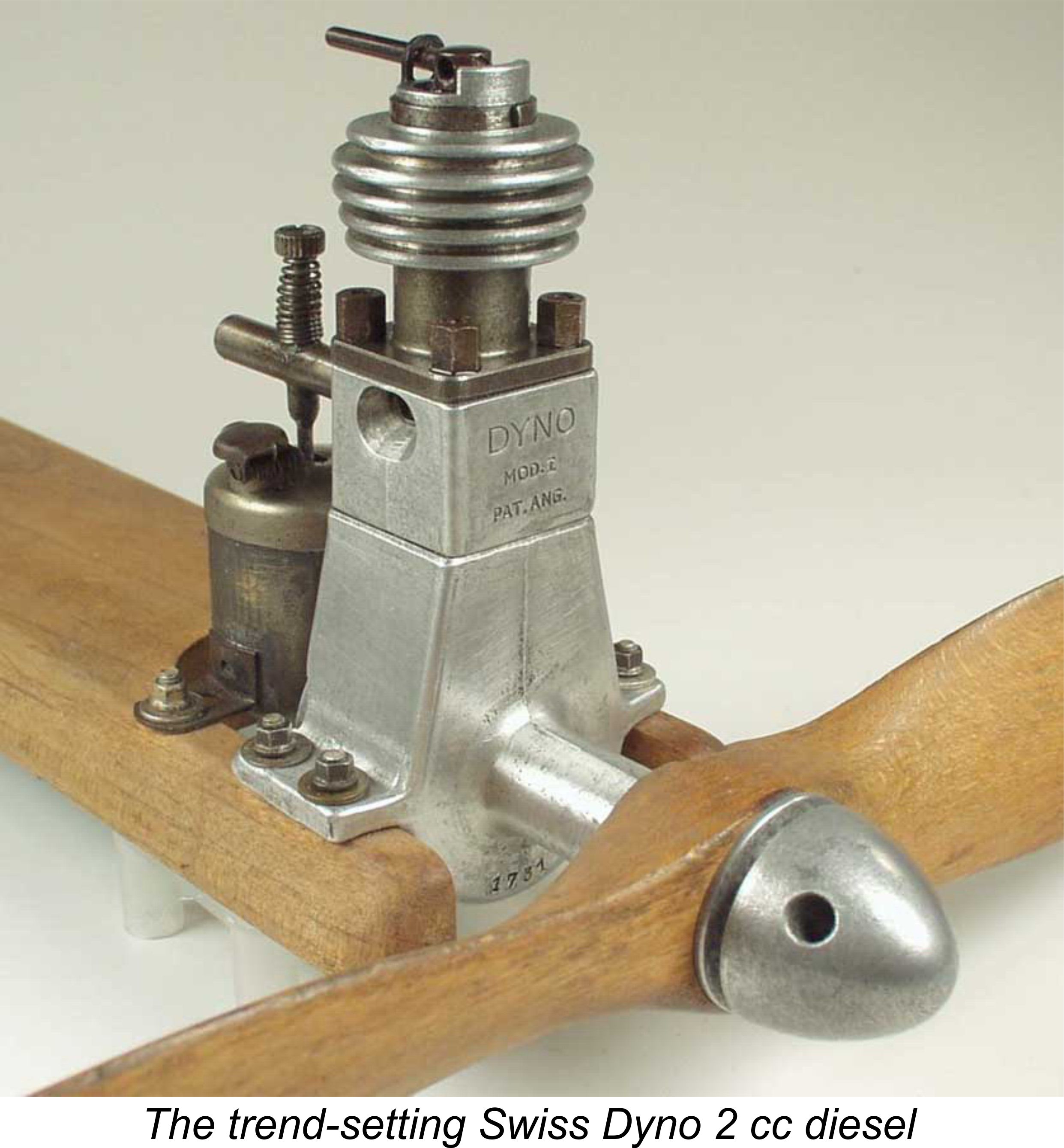
Somewhat surprisingly, the Pioneer received a retrospective mention in this article despite the fact that it had been out of production for some time. Since this seems to represent the engine's sole appearance in a contemporary English-language publication, the relevant paragraph (written during the latter part of 1952) seems worth quoting in full: "One does not usually associate firms of the status of Carl Zeiss with model aircraft matters but, in fact, this world-famous manufacturer, also located in East Germany, did announce a 2 cc diesel known as the "Pioneer 1" some time ago. Whether, in fact, the engine went into series production seems doubtful, however. From the scant details available, the design of the motor showed little originality, the weight was rather high and the performance would probably be more closely related to the early diesels which stemmed from the Swiss “Dyno”, than to more recently developed designs". As it turns out, Chinn was woefully misinformed on several points covered in the above paragraph! However, he was right on one important count - despite its 2 cc displacement, the Pioneer was designated the "Pioneer 1" by its manufacturers, presumably reflecting the fact that it was the company's first model engine and was hence pioneering the company's entry into an entirely new market area. In recent years the engine has not infrequently been referred to as the Pioneer 2, which is incorrect. Now let's see for ourselves just how misinformed Chinn was on other points by beginning our own in-depth look at this very unusual engine. The Zeiss Pioneer 1 - Description
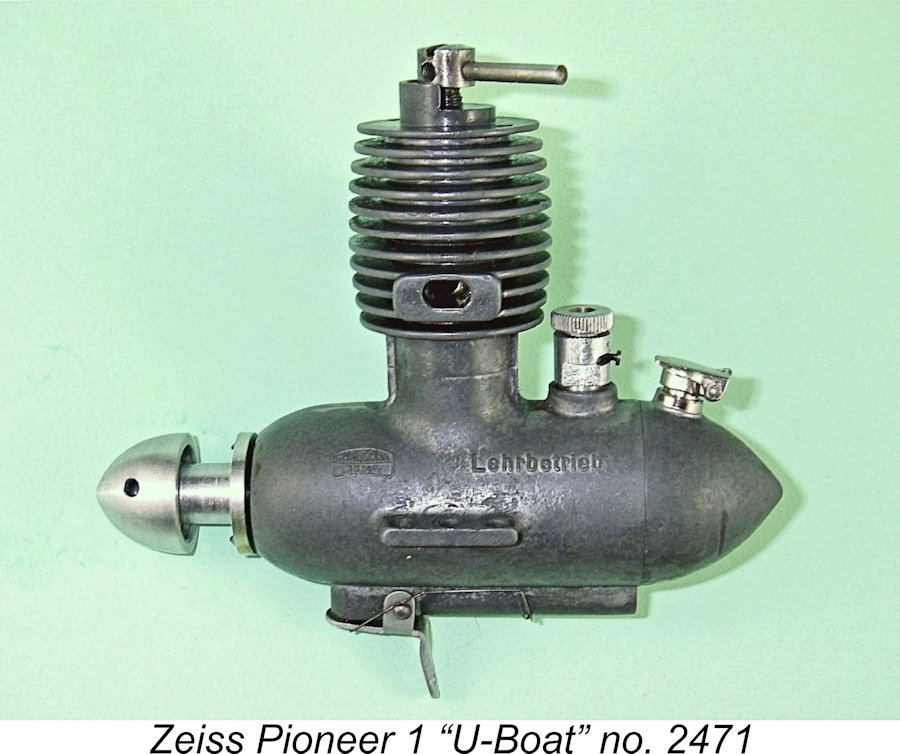
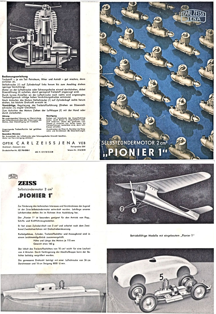
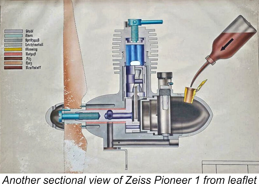
Not only that, but the company also produced a very lavishly-presented promotional leaflet, as reproduced below at the right. This leaflet set out the Pioneer's technical characteristics and claimedadvantages in some detail, also highlighting the range of The next point on which Chinn's report fell well short of the truth is the question of the design originality of the Pioneer. It's actually a little difficult to know where to start in describing this highly individualistic design! How Chinn ever got the idea that it displayed "little originality" is quite beyond any rational explanation other than a lack of authoritative first-hand knowledge on the part of his informants, perhaps exacerbated by linguistic difficulties and/or political divisions! In reality, the design of this engine is so out-of-the-rut that it's difficult to escape the conclusion that its designers were very little influenced by precedents - perhaps there were no previous designs readily available to hand?!? The Swiss Dyno had exerted a very strong influence upon model diesel design Perhaps we should begin with a few basics. The Zeiss Pioneer 1 is a 2 cc variable compression model diesel featuring crankshaft front rotary valve (FRV) induction allied to a twin ball-race crankshaft and reverse-flow scavenging. The engine is built around a set of very well-produced castings in magnesium alloy. These include the main crankcase casting, the screw-in back tank and the screw-on cooling jacket. Checked weight is 147 gm (5.18 ounces), a very modest figure by the standards of the day, especially for a 2 cc twin ball-race FRV diesel complete and ready to run with tank. On this point too, Chinn appears to have been misinformed. No doubt the use of magnesium alloy castings helped to achieve this relatively low figure. Given the engine's rarity, especially in the condition of my own example, I was not prepared to risk the tightly-assembledmagnesium castings by dismantling it for inspection. However, it was possible to determine the bore very accurately by taking measurements through the twin opposed exhaust ports. The bore turned out to be 13.0 mm. With this figure in hand, the engine's stated 2 cc nominal displacement provided a basis for calculating the engine's stroke. It turns out In terms of its appearance, the engine is most definitely a one-off - you couldn't mistake it for any other model of which I'm aware, regardless of origin! German engine aficionados were quick to note the fact that the shape and surface appearance of the engine's crankcase and screw-in tank assembly combined with the cylinder to give it a very general but nonetheless unmistakable similarity to the German U-boats of then-recent memory. As a result, the engine became known to German modellers by the affectionate nickname of "Das U-Boot" (The U-Boat)! It seems to be well-known by that name among today's German collectors. The engine's unusual appearance does much to obscure the fact that in terms of its mechanical design at least, the "U-Boat" is basically a fairly conventional FRV diesel of its day. The accompanying sectional view of the engine extracted from the leaflet should help to clarify the engine's construction.
This raises an interesting point - the drawings in the manufacturer's leaflet do not depict the use of ball bearings for the crankshaft! I infer from this that there were two distinct The piston is lapped into the cylinder and has a band of diametric relief between the upper and lower sealing portions of the skirt. This band of relief actually occupies much of the piston skirt length. I'm extremely grateful to my good friend Peter Valicek for providing the accompanying images of the piston assembly. These images show that the gudgeon (wrist) pin is mounted in a separate light alloy carrier which screws into the interior of the working piston. This arrangement prevents any possibility of the ends of the gudgeon pin fouling the transfer ports, also contributing to The other image provided by Peter (left) shows that the piston crown features two small holes which are clearly intended to provide a secure purchase through the use of a pin spanner while tightening the gudgeon pin carrier into the piston. Cylinder porting is basically quite conventional, as seen in the accompanying image at the left. The leaflet drawings confirm that the twin transfer ports are supplied with fuel mixture by twin bypass passages formed in the visible crankcase expansions fore and aft. These bypass passages feed upwardly-angled transfer ports located at the front and rear of the cylinder liner. Twin exhaust ports are placed between these transfers, one on each side. In fact, the porting seems generally similar to that encountered earlier with such engines as the Vivell diesels and (later) the Barbini and Cox ranges. The cylinder jacket is of the screw-on variety, being provided with a pair of holes at the top to allow the use of a pin spanner. This is undoubtedly how the cylinder liner is installed and secured. Some early engines feature aluminium alloy jackets, while others such as my own illustrated example are made from magnesium alloy. The jacket incorporates an integrally-cast stop to limit the amount of compression adjustment - probably a very good feature for In connection with this feature, a noteworthy point is the inclusion on my example of a slot at the top of the steel compression screw. This is a very sensible provision indeed, since it allows one to operate the comp screw by using a screwdriver for the initial start with the control arm removed, thus not being fettered by the compression stop. Only once the proper setting is established need the control arm be installed in the appropriate hole. Doubtless this was how the factory test runs were conducted. The earlier engines exemplified by engine number 159 seemingly lacked this feature.
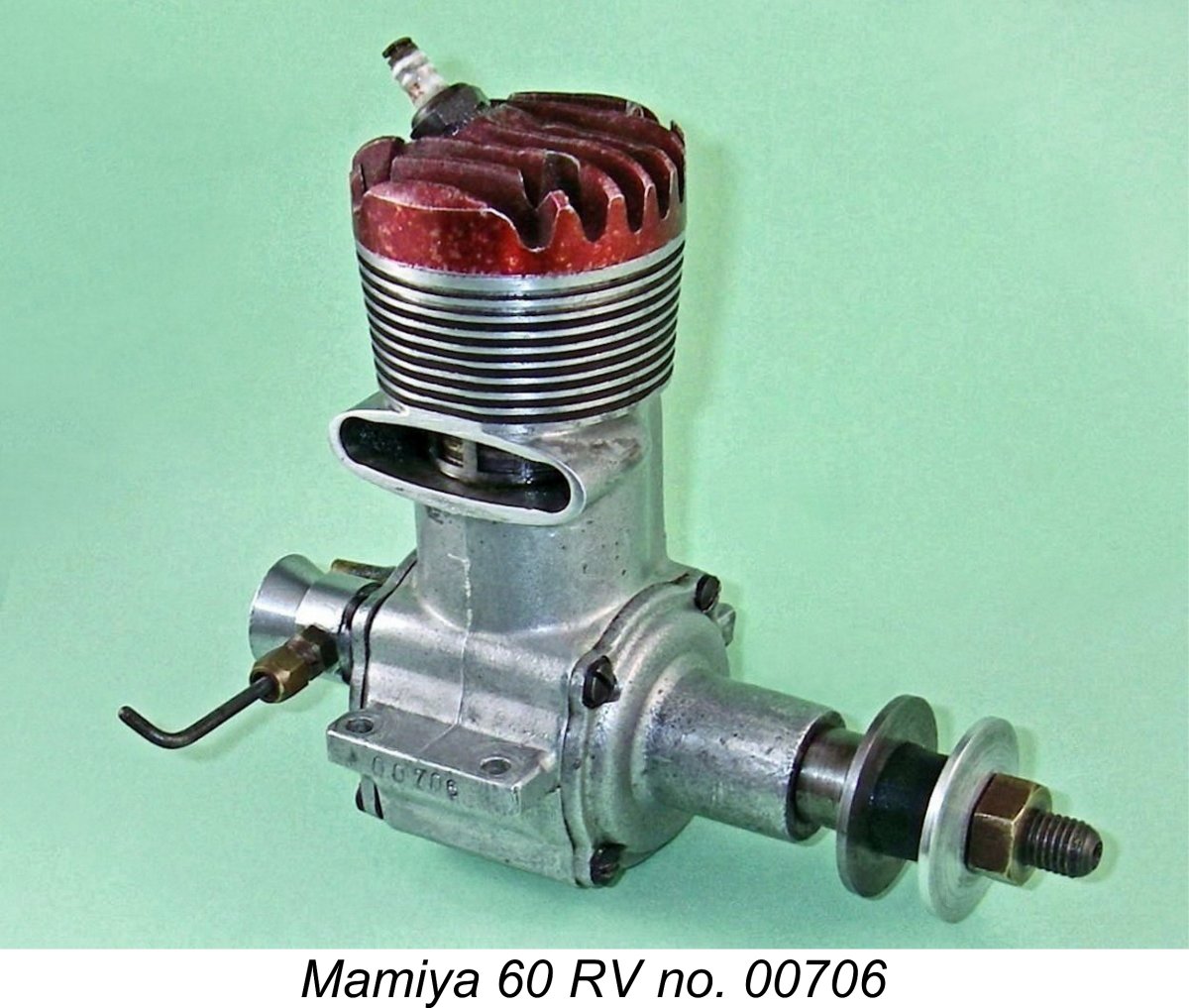
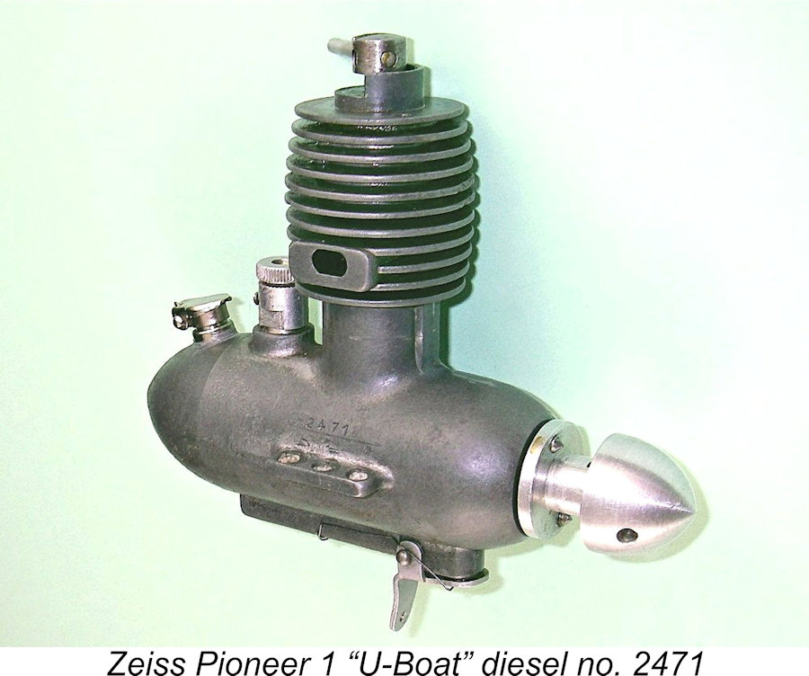
The aluminium alloy prop driver lacks any form of serrations for grip, relying instead upon a pair of short pointed steel studs to prevent prop slippage. The previously-reproduced sectional drawings from the instruction leaflet confirm that the driver is fitted onto a taper at the front of the shaft. The front of the shaft is internally threaded to accept a slot-headed machine screw which secures the prop with a washer, also of light alloy. So far, this is effectively the same system as used in the later Jena models apart from the different means of preventing prop slippage. However, it doesn't stop there - the complexities continue to mount! The front of the prop mounting spigot is slotted at one point in its circumference. This slot accommodates a steel pin which is pressed into the rear of the prop washer, thus constraining the prop washer to turn with the driver. This minimizes any tendency for the prop to slip by providing two driving faces. Somewhat reminiscent of the interlocked prop driver and prop washer seen on the earlier E.D. Mk. II model. The main problem with the system as applied to the Pioneer is that it limits the engine to accommodating a very narrow range of prop hub thicknesses if this feature is to be effective. All very complex, you may think. But wait ........... there's even more! The outer circumference of the rather thick alloy prop washer is externally threaded to accommodate an internally-threaded alloy spinner. Although this looks like a conventional spinner nut when installed, I hope that the above description and accompanying photos will have made it clear that the spinner plays no role whatsoever in securing the prop - it merely improves the engine's appearance. The engine will run perfectly well without the addition of the spinner. A final oddity which seems worth mentioning here is the fact that the mounting lugs have three holes each instead of the more usual two. All examples of my acquaintance have been so equipped, so I'm sure that the engines were supplied this way. It's a bit difficult to understand why ............... Further details of the engine's internal construction are not available given my decision not to subject this example to the rigors of dismantling and re-assembly. However, the comment may fairly be made that the quality of construction of this little-used example of the Pioneer 1 appears to be well up to the best standards then prevailing. There is no trace of play anywhere in the mechanical assembly, nor is there the least sign of binding or tightness when the engine is turned over. Compression seal is outstanding. The two ball-races seem to be of excellent quality as well as being very well fitted, giving the engine a delightfully "silky" feel when turned over. Somewhat unusually, the shaft in my example is a smooth push-fit in the centre of the two races. This may be a concession to the challenge of assembling the shaft through the very deeply-recessed crankcase opening inside the fuel tank. Model Identification The Zeiss Pioneer engines apparently all bore serial numbers which were neatly stamped above the right-hand mounting lug (looking forward in the direction of flight). Although the sample of examples for which authoritative numbers are available is very small (three confirmed numbers only at present), the range is considerable - from engine number 159 all the way up to my own engine number 2471 and engine no. 2472 (amazingly, the very next example off the line!) which Peter Valicek restored for Dean Clarke. My friend Sten Persson reports owning engine no. 2474, again very close to two of the others. There is also a report of at least one un-numbered example, of which more below in its place. This creates something of an interpretive challenge for the historian. If we take these numbers at face value, the implication would be that these engines were made in far larger numbers than their minimal present-day survival would lead us to expect. If these two numbers are part of a numerical sequence beginning at engine number 1, we would appear to have evidence that at least 2500 or so were manufactured. Such a number seems highly inconsistent with the Pioneer's present-day rarity. I for one find it difficult to accept.
A plausible alternative scenario leading to the same conclusion arises from the fact that there appear to have been two distinct variants of the Pioneer 1 (plain bearing and ball race). We might expect to see other detail changes between two such distinct variants of the same model. An observation which supports this possibility is the fact that engine numbers 159 and 2471 appear to differ slightly in certain externally-visible details (the unslotted comp screw, the aluminium alloy tank and cooling jacket and the absent fuel mixture control punch-mark on number 159 being examples). These differences imply that engine no. 159 is a different model, possibly to the extent of being a plain bearing unit. The use of different prefixes for distinct variants would be entirely understandable - perhaps 1 for the plain bearing units and 2 for the ball-race versions. However, even the 530 minimum production figure which this would imply seems hard to accept. Another completely unsubstantiated possibility is that the initial digits (1 and 2) represent the year of production (1951 and 1952) with the second digit representing the month or production (May and April respectively). This would make engine no. 159 the 9th unit produced in May 1951, with engine no. 2471 being the 71st unit produced in April 1952. It is also possible that the last digits represent the total number of engines produced from the commencement of manufacture up to the indicated date. Such figures appear to be far more consistent with the engine's present-day rarity, but we’ll probably never know! Only the sharing of more serial numbers combined with structural details would help to resolve this matter - we'll have to leave it unresolved for the present. Of course, all of the above scenarios appear to deal very decisively with Peter Chinn's previously-noted doubts that the Pioneer ever made it into series production! There's no doubt at all that production at some level was pursued by Carl Zeiss Jena, even if only for a relatively brief period. On the left-hand side, the engines bore a rendition of the Carl Zeiss Jena logo along with the word "Lehrbetreib", both cast in relief onto the case. The word "Lehrbetrieb" means "Teaching" or "Training" in German. This certainly implies that the intended purpose of the engine's production was to stimulate training opportunities for East German modellers through the gaining of hands-on experience. Perhaps the name "Pioneer" which was used to characterize the engine to English-speakers such as Peter Chinn was a reflection of this goal. Fuel Supply Complexities
Given the complexities involved in this aspect of the engine's design, we have to take things one step at a time to minimize confusion. It's perhaps best to begin with the air pathway involved, leaving the discussion of fuel supply until later. The accompanying sectional view extracted from the manufacturer's leaflet may help to clarify things somewhat. Although the Pioneer is at heart a conventional FRV design, the actual air intake is very far removed from its usual location adjacent to the main bearing housing. In fact, the engine draws its main air supply from a primary intake located at the top of the fuel tank at the rear! This intake is located at the top of a screw-in induction tube which passes vertically right through the fuel The rear end of the horizontal passage obviously has to be blind in order to maintain suction through this system. This is achieved by the simple expedient of plugging it with an aluminium alloy stopper, which is visible in several of the attached images showing the engine from the rear. There's no provision for a gasket or an O-ring at the base of the induction tube. The engine seemingly relies upon a close fit between the base of the induction tube and its socket in the tank base to prevent fuel from short-circuiting the metering system. A minor amount of "weeping" probably doesn't matter much, since it should be relatively constant once the engine is running.
On the illustrated example, the closure of the secondary intake by the flap valve is far from perfect. The previously-reproduced drawings from the manufacturer's leaflet confirm that a non-metallic pad was glued to the flap to improve sealing. However, this pad is missing from my example. A temporary pad of this nature can of course be inserted for test running purposes if required - the spring tension will keep it in place unless or until the timer is activated. More of this below in its place ........
It's interesting to note that the drawings from the manufacturer's leaflet do indeed appear to show the crankshaft induction port positioned for left-hand rotation - have a look for yourself. It would be interesting to know if the Pioneers were all supplied in this configuration. It's perfectly true that a number of other European and Scandinavian rotary valve engines were arranged for left-hand rotation - I've tested a few examples myself. There doesn't appear to have been the unanimity of opinions regarding the direction of prop rotation that developed as time went on. ............... Anyway, now we know how the engine is supplied with air - what about the necessary fuel? This is perhaps the most unusual aspect of this engine's already highly individualistic design. Please bear with me ............. this isn't going to be easy!
The presence of the plastic sheath naturally causes the external groove in the induction tube's exterior wall to take on the form of a fuel supply conduit leading upwards from the bottom of the fuel tank to the top of the induction tube. The fuel supply line formed in this manner communicates with the interior of the induction tube through a small aperture formed in the wall of the induction tube near the top. Since I was unwilling to remove the age-hardened plastic sheath, the precise size and form of this aperture remain unknown. Production considerations suggest that it is most likely a drilled hole. Whatever its shape, it clearly functions as a surface jet. Fair enough - so that's how the fuel gets from the tank into the induction airstream. But how is it metered? Again, in a highly original manner, as we have by now come to expect from this engine! An internal rotary sleeve is inserted into the top of the induction tube. This sleeve has a knurled control knob which can be used to rotate it within the induction tube. This component is of course centrally drilled through to allow the passage of air, albeit necessarily at a lesser diameter than the main induction tube. The actual internal diameter of the sleeve aperture as supplied is 3 mm.
The key trick is that the lower edge of the sleeve inside the induction tube is cut at an angle. As a result, when the sleeve is turned, the vertical elevation of its lower edge within the induction tube varies at the fixed location of the fuel jet aperture. This cut is very precisely located so that when the sleeve (or mixture control, as we should now call it) is turned fully clockwise (viewed from above), the lower edge of the sleeve more or less completely obscures the fuel supply aperture in the wall of the induction tube. By contrast, when the mixture control is turned fully anticlockwise (again viewed from above), the fuel supply aperture is fully open. I confirmed this myself by pressure-testing the fuel supply system while manipulating the mixture control sleeve. It has to be said that all of this looks far more complex than necessary! The assembly must also have been very expensive to manufacture by comparison with a conventional needle valve set-up, especially given the required degree of precision. However, one imagines that a highly experienced precision optical instrument company like Carl Zeiss would find this to be child's play! Even so, it's very difficult to detect any operational advantage here. I would objectively expect to find that establishing the perfect mixture using such a relatively coarse control (less than ¼ turn from full rich to full lean) would be problematic. A great deal would depend on the appropriate sizing of the fuel supply aperture in the wall of the induction tube. We must assume that the Carl Zeiss company most likely got this right ………...but even so, the effect of the slightest vibration of the fuel metering sleeve inside the induction tube would play havoc with consistency. In the latter regard, another puzzle which my example presented initially was the seeming absence of any means of preventing the mixture control from wandering while the engine is running - no form of friction device was fitted to the engine as received. I would have expected to find some kind of spring device bearing against the knurled edge of the mixture control knob.
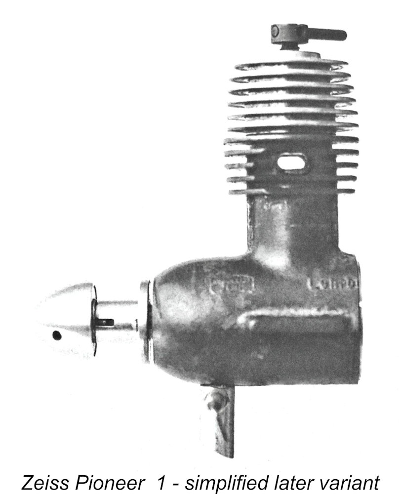
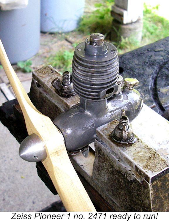
By way of confirmation, the accompanying photograph of another example (no. 159) which came to my attention during the original writing One point worth noting with respect to engine number 2471 is the fact that a small punch mark appears on the top of the induction tube above the annular slot which accommodates the sleeve retaining screw. This appears likely to be the starting or running setting established at the factory during the engine's test run. Since I don't have access to an instruction sheet, I’m unable to confirm this deduction. A major downside arising from all of this complexity was the fact that the engine could only be run with its standard back tank and moreover could only be used in an upright configuration. This would have severely limited its potential range of applications. In particular, control line service was a non-starter. The tank was far bigger than required for free flight, so the cut-out was really necessary. The overriding impression gained from a detailed examination of this engine is of a high-quality product displaying a considerable degree of original thinking but designed to a level of complexity which must have It's evident that Zeiss Jena themselves came to the realization that the Pioneer 1 was an unwarrantably complex design in some respects. They eventually came up with a revised model which represented a considerable simplification of the original unit. This very rare variant dispensed with the rear tank/carburettor assembly as well as the induction tube running forward beneath the crankcase. Induction was now accomplished entirely through a separate screw-in updraft intake at the front, with a conventional needle valve and spraybar handling the fuel mixture adjustment chores. This variant of the engine could be mounted in any orientation, greatly expanding the range of applications in which it could be used. In particular, it was entirely suitable for use in control-line models. I would also expect it to feature superior fuel mixture control characteristics. Anyway, now we know how the "U-Boat" is intended to function. How well does it actually do so? Let's take a test dive ............. The Zeiss Pioneer 1 on Test I have to admit that I felt some hesitation when considering the idea of giving this engine a few test runs. If anything went amiss, this was one engine that would be hard to fix and well-nigh impossible to replace. However, I actually have a good deal of experience testing fragile and/or mega-rare diesels, so far with no ill effects thanks to very careful pre-inspection and handling. This comforting awareness combined with my curiosity regarding the unique fuel system eventually encouraged me to give it a go. Certainly, someone should do this, and it seemed unlikely that anyone else would ever do so for the record .............. Needless to say, I went at this task very carefully indeed. The first issue to be overcome was the previously-mentioned fact that the engine is timed for reverse operation. This meant that a pusher prop had to be used. All that was available was a 12x6 wood pusher, which I could progressively cut down to a suitable size as indicated by the engine's performance characteristics. However, I would have no torque absorption data for the series of makeshift props created in this manner. Consequently, I was forced to accept the fact that this test would be confined to an opportunity to experience and report upon the engine's starting and running characteristics, as opposed to my usual full horsepower tests.
Of course, I now had no idea where the correct setting lay! Accordingly, I elected to begin testing with the control arm removed, manipulating the comp screw with a screwdriver using that very handy slot for purchase. Once the setting was established, the control arm could be re-installed. The previously-cited illustrated instruction sheet included the information that the engine was intended to run on a fuel containing equal parts of ether, kerosene and castor oil. I brewed a fresh batch of fuel to this precise formula. Based on past experience with 2 cc diesels of this vintage, I began with the 12x6 prop prop cut down to 10 inches in diameter. This made it a bit of a club, with a significantly larger blade area than would be normal for a prop of this size. I was quickly reminded that flicking in reverse is not one of my favourite pastimes! I found it best to set the prop against compression at "ten past four", allowing a fairly powerful downward flick with the right hand. Still a bit awkward, but it did seem to provide enough urge to provoke a start if all was well. For the initial attempt, I left the cut-out flap on the secondary intake operating without any form of sealing gasket. I also set the fuel control sleeve at the "maximum rich" setting. The engine proved to be very easy indeed to get firing, starting up in a short burst within a few flicks after setting the compression by feel and administering a light prime. Thankfully, only a very lazy flick was necessary to achieve this result. However, the engine died out immediately, clearly due to fuel starvation. It was also obvious from the rather lacklustre nature of the burst in question that the 12x6 prop cut down to 10x6 was still too much prop for the engine. This prompted me to do two things. First, I re-trimmed the prop to 9-inch diameter. It was still a bit of a club with its grossly exaggerated blade area, but I reckoned that the engine would have a far better chance of reaching speeds at which suction would improve. Secondly, I inserted a small rubber pad cut from an old bicycle inner tube between the cut-out flap and the updraft secondary intake, allowing the cut-out spring to hold it in place. This provided a very good seal at that point, undoubtedly enhancing suction from the primary intake at the rear of the engine. With these modifications aboard, I tried again. As before, the engine started up very promptly indeed following a light prime - I'd actually rate it as an extremely easy starter. However, it still would not continue to run - it merely took a little longer to cut out due to apparent fuel starvation.
I finally resorted to the expedient of making an insert for the main intake having an internal diameter of only 2.25 mm as opposed to the 3 mm diameter of the standard unit. This reduced the throat area at the point of entry by some 44%, which I felt should be roughly equivalent to my partially choking finger. The insert can be clearly seen in the running shots of the engine. With this modification aboard, the engine would keep going and would run the tank out much of the time. However, as the last statement implies, all was not perfect - the engine would run very smoothly for a while but would then begin to lean out progressively over a period of time, finally beginning to "hunt", occasionally to the point of stopping altogether. I actually went through the fuel system once again to see if there was a partial or intermittent blockage anywhere (such as a piece of old castor gum), but it all seemed quite clear. I have no definite explanation for this behavior - only a complete dismantling of the system (which I was not prepared to undertake) might reveal the cause. The fact that the engine will not keep going at all on the standard intake certainly supports the view that something is not quite right inside.............. The crankcase compression seal is excellent, so a loose backplate or leaky crankshaft seal are definitely not the culprits here. For me, the most likely cause of this behavior is an undetected leak in the seal between the well-aged plastic sheath and the induction tube which passes vertically through the tank. Such a leak would allow the entry of unwanted air into the fuel line. I hope that my earlier description will have made it clear that the integrity of what amounts to the fuel line depends completely upon this seal being maintained. Since the symptoms are very much akin to those encountered with a leaking fuel line, I feel that this may well be the correct diagnosis. However, leak or no leak, I'm keeping the original sheath in place! The other possibility is that there may be a piece of well-congealed castor gum or even a foreign particle of some kind around the fuel jet which I’ve failed to dislodge. This would certainly play havoc with the engine's suction and consistency.
The Pioneer managed to turn the 9x6 "club" of a prop which I had inflicted upon it at a steady 5,100 rpm (when things were stable). I have no idea what this translates to in terms of output, but that prop is definitely a major torque-absorber - far more so than an equivalent APC or Taipan prop as normally used for my testing. The engine would definitely turn a 9x6 of either of those types at a considerably higher speed. However, it's clear that performance is by no means stellar. The relatively low speed achieved with this prop raises the possibility that the engine needs to be operated at a higher speed for the fuel supply system to work correctly. 5,100 rpm is a very low speed for an FRV ball-race diesel having what appears to be quite adequate cylinder porting for effective scavenging. This might be another explanation for the engine's erratic behavior. Once I had a compression setting that seemed to be pretty stable, I re-fitted the control arm to the comp screw. This revealed a major downside of the system used to keep compression movement within fairly narrow limits - if the engine becomes flooded, you can't back off compression enough to clear it. I did manage to flood it once by over-priming, necessitating the removal of the arm once again to facilitate clearance of the excess fuel at a reduced compression setting. While the compression control was very responsive, the same could not be said for the fuel mixture control. I found that while the engine held a given setting very well (my home-made spring worked perfectly), changing the setting and then returning to the former position did not always restore the same mixture. In fact, the system appears to be far less predictable than desirable, even seemingly changing between runs at the same setting! This may of course be due to whatever is wrong with the fuel system rather than an inherent fault. Even so, I reckon that a conventional needle valve set-up would have provided far superior results. All that complexity doesn't appear to have achieved much of any real value!
On the basis of this admittedly incomplete test, I'd rate the Pioneer as a very well-made engine indeed which is a sweet runner as well as being a genuine delight to handle, albeit displaying some issues with the fuel supply system which affect the unit's consistency. This is most likely due to some residual unresolved problems with this particular example, but nonetheless I'd be remiss in not reporting that the engine's fuel supply arrangements appear to me to be less than ideal. The above impressions were reinforced by the experience of my valued friend Peter Valicek of the Netherlands. Peter restored a somewhat abused example of the engine, returning it to excellent working order. Peter's engine must be a very early example, since it bears neither a serial number nor any additional markings such as the Zeiss Jena logo or the "Lehrbetrieb" designation. An excellent video showing Peter's restoration activities as well as the initial test run is available for your viewing pleasure. Suffice it to say here that the engine did Peter proud, starting on the 3rd flick and running very smoothly. During the final lean burst as the tank ran dry, it got the 11x6 wood test prop up to around 4,800 RPM - not bad for a 2 cc diesel! Peter was understandably quite impressed! Well done, mate! The Later Years at Zeiss
After what may well have been a less than satisfactory experience with the Pioneer in commercial terms, the Zeiss Jena company evidently retreated from the model engine field for a considerable time. This retreat seems to have occurred in 1952. Writing about German engines in late 1952, Peter Chinn referred to the Pioneer 1 in retrospective terms, as noted earlier. There was no mention of any new designs from this manufacturer for some years to come, despite the increasing attention paid to East German products as the 1950's drew on. Peter Chinn's comprehensive survey of model diesel engines for 1954-55 ("Model Aircraft", April 1955) made no mention of any Zeiss models, although other East German products such as Willi Otto's Wilo offerings were included. The arrival of the East German Schlosser engines on the Western market was duly noted in late 1955, but there was still no indication of any renewed activity from Zeiss. The first intimation that things might be about to change came once again from Peter Chinn, who noted in his January 1956 "Foreign Notes" column in “Model Airplane News” (written of course in late 1955) that East Germany had hitherto suffered from a lack of suitable competition engines but that he had recently received word that "several new models are now in various stages of development". Confirmation of the accuracy of this information came in the form of a further article by Chinn in the April 1956 issue of “Model Aircraft” under the title "East of the Iron Curtain".
The makers subsequently added to this confusion by introducing 2 cc versions of the Aktivist IV and V models. Why they did so is not clear ...... The 2 cc reed valve version was the subject of a test by Peter Chinn which appeared in the October 1962 issue of "Model Aircraft", while the disc valve model was covered in Ron Warring's report which appeared in the March 1964 isue of "Aeromodeller". In both cases, the engines demonstrated levels of performance which were well up to then-accepted standards for general-purpose sports diesels. The early examples of these engines bore the full name of their manufacturer - VEB Carl Zeiss Jena. Later examples confined themselves to bearing the name Jena along with the letters DDR to indicate their zone of origin. All of them were quite strong runners by the standards of their day, as I can attest from personal experience.
In various configurations, the Zeiss engines actually became quite widely distributed among Western modellers during the 1960's, resulting in a considerable number of examples still surviving today. The range continued to be manufactured at least up to the late 1960's and possibly longer. The Zeiss Jena engines were still featured in the list of the world's model engines which formed part of the 1968-69 “Aeromodeller Plans Handbook”. At present, this is the latest reference to the range which has come to my personal attention. It is of course entirely possible that production continued past this point - perhaps some kind reader can enlighten us further?!? Overall, the Jena engines tended to be good designs which were inconsistently executed in some respects. In addition, access to raw materials was somewhat sporadic, involving a greater-than-normal reliance upon scrounging (aka "recycling" these days!) to obtain materials. Consequently, the material specifications embodied in the engines tended to lack consistency. This inconsistency carried over to the ball races which were used - their quality was extremely variable. The best were very good, while others were highly suspect. There was also a tendency to fit the engines too tightly initially. This applied to the ball races as well, explaining the somewhat lumpy feel of the bearings which is frequently encountered with new examples as well as the near-impossibility of extracting them for servicing or replacement! Be warned .................. A number of individuals have commented that the individual components of the Jena engines were generally quite well made - it was the standard of assembly that tended to let them down, along with a degree of material inconsistency. There was nothing wrong with the designs - a good example was very good indeed, as my own experiences have shown. However, construction standards varied considerably. If additional source information comes to hand, I hope to present a more detailed summary of the Zeiss Jena engines at some future date. Meanwhile, it's now time to conclude our present discussion of that first Zeiss model of them all - the "U-Boat". Conclusion The serial numbers of which we are presently aware imply that at least a few hundred examples of the "U-Boat" were manufactured in total – it may well have been more. Under normal circumstances, we would expect even these relatively small numbers to throw up far more survivors than actually seems to be the case. Even in its native Germany, the engine is considered to be extremely rare today. This present-day The effects of corrosion would doubtless have been exacerbated by the fact that the engine was dated in design and performance terms more or less as soon as it appeared. Despite the considerable originality of thought displayed in its design, there's no question that the designers had missed this particular boat. Moreover, the engine's range of potential applications was also quite limited. As a result of these two factors, those examples that did find owners probably fell out of use quite quickly, living up to their nick-name by rapidly sinking out of sight! Once set aside, it's unlikely that many examples received the ongoing care that magnesium-case engines require if they are to survive. Finally, the fact that its manufacture took place behind the Iron Curtain at a time when that ponderable edifice was still very firmly intact doubtless prevented the "U-Boat" from entering widespread circulation outside of its zone of production. The fact that the East German population had other priorities than model engine preservation during the 1950's would not have encouraged the payment of much attention towards the preservation of these engines. Still, a few survivors remain with us to attest to the "U-Boat's" existence. These survivors confirm that while the engine was certainly no world-beater, it did represent a commendable and highly original first effort by the Zeiss company as they moved into a completely unfamiliar sphere of precision manufacturing. I hope you'll agree that the Pioneer is an unusual engine with a proud heritage which constitutes a most interesting reflection of its time and place! _______________________________ Article © Adrian C. Duncan, Coquitlam, British Columbia, Canada First published on MEN November 2013 Re-published here November 2024 |
 In this article, I’ll turn the spotlight on one of the near-mythical products of the early post-war German model engine manufacturing industry - the Zeiss Pioneer 1 diesel of 2 cc displacement, affectionately known as the "U-Boat" for readily-apparent reasons. This was the first model engine produced by the famous
  company went on to manufacture a range of highly-regarded model diesels under the Jena name, which reflected the engines' city of origin. These later models met with some success in Western markets, resulting in the Zeiss Jena name becoming quite well known among diesel modellers outside East Germany. However, this did nothing to rescue the old Pioneer from the obscurity in which it had languished ever since its all-too-brief heyday. That remains for me to do!
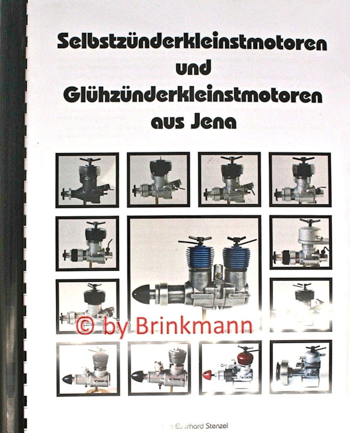
 high-quality optical equipment such as microscopes, cameras, binoculars, etc. It is almost certainly the oldest surviving manufacturer of optical systems in the world as well as one of the most respected.
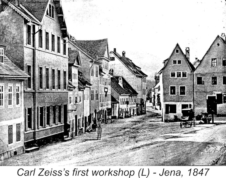
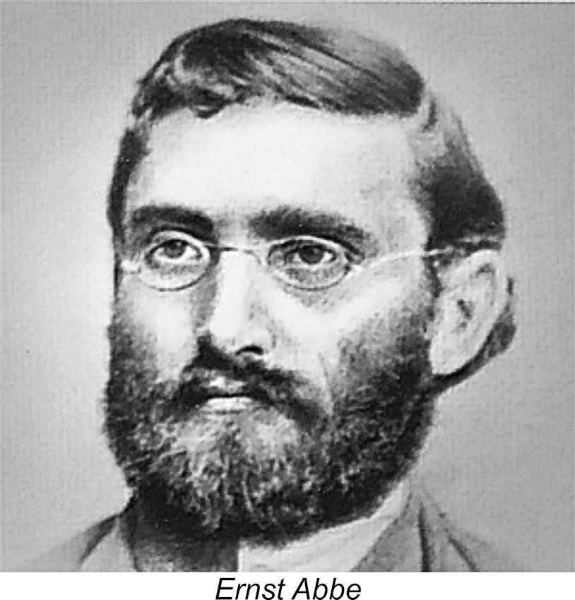 In 1866, Carl Zeiss took on a partner, the rising 26-year-old physicist Ernst Abbe (1840 - 1905), who served as the company's Director of Research, working on the scientific development of improved lenses for the company's products. Abbe was later followed into the partnership by Otto Schott (1851 - 1935), who had been working independently on the development of superior glass formulations for optical applications. Schott officially joined the management and research team at Zeiss in 1884 at the age of 33, bringing his glass-making expertise with him.
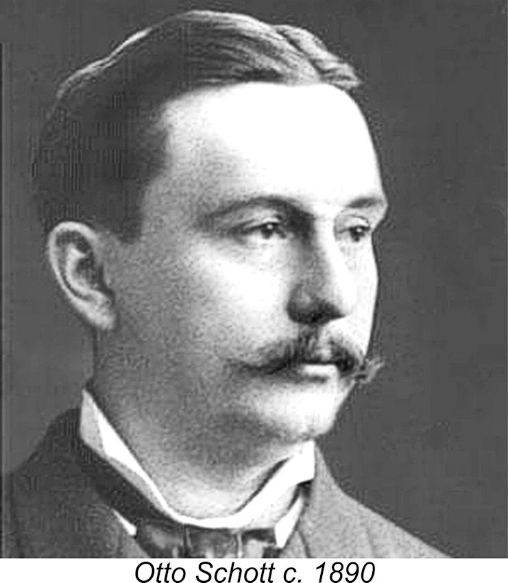
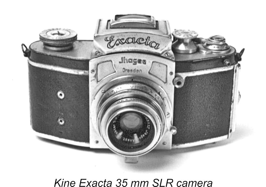 Returning to the pre-WW2 period, the company continued to develop innovative optical products between the wars. A major achievement which pre-dated WW2 was the development of the world's first 35 mm single-lens reflex (SLR) camera, the Kine Exacta, by one of Zeiss's Dresden subsidiaries. This was followed up with the company's famous 35 mm Contax rangefinder camera. In addition, the world's first true miniature camera which delivered acceptable picture quality was developed by Zeiss during this period.
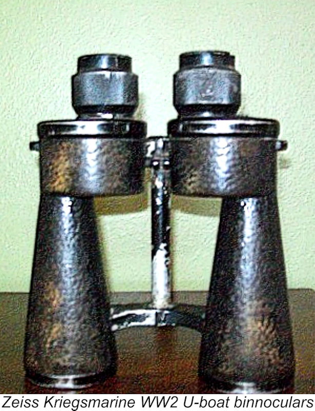 Even so, it appears that a number of those in charge at Zeiss during this period were less than fully sympathetic to the Nazi viewpoint, since there are a number of documented instances of intervention by the Zeiss Personnel Department to obtain the release of certain foreign labourers who had been arrested for various "offences against the Reich". As long as these workers had the required skills and did their jobs, the company doesn't seem to have cared much whether or not they conformed to Nazi expectations of behaviour.
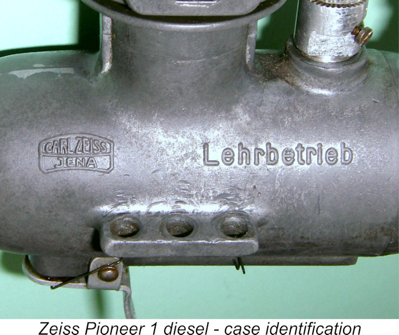 avoid confusion regarding the origins of their products, the West German Zeiss products were labeled "Opton" for sale in the Eastern bloc, while East German Zeiss products were labelled "Zeiss Jena" or "Carl Zeiss Jena" for sale in Western countries.
 Taken together, these facts clearly imply that the manufacture of model engines must have been undertaken for one of two possible reasons. Firstly, the engines could have been manufactured essentially as a labor of love at the instigation of someone within the company who had a very strong interest in models as well as enough influence with the company (and its State controllers) to persuade them to enter a manufacturing field which was quite distinct from their previous line of business. There are a number of precedents for this - the
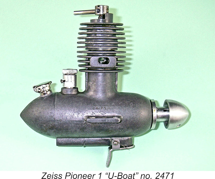
 The writing of the article was doubtless triggered by increased interest in German engines given the fact that Germany had then recently been re-admitted to international model competitions following a period of banishment after the conclusion of WW2. A small German team had made an impressive come-back showing at the 1952 World Free Flight Power Championship meeting held in September at Dubendorf Aerodrome in Switzerland. Using then-current
 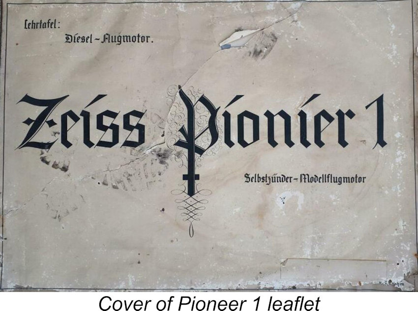 The first point on which Chinn appears to have been misinformed was the question of the production status of the Pioneer 1. His expressed doubts about the engine ever having entered series production were clearly unfounded. Apart from the serial number evidence to be discussed below in its place, the manufacturers went to the expense and trouble of commissioning the well-known
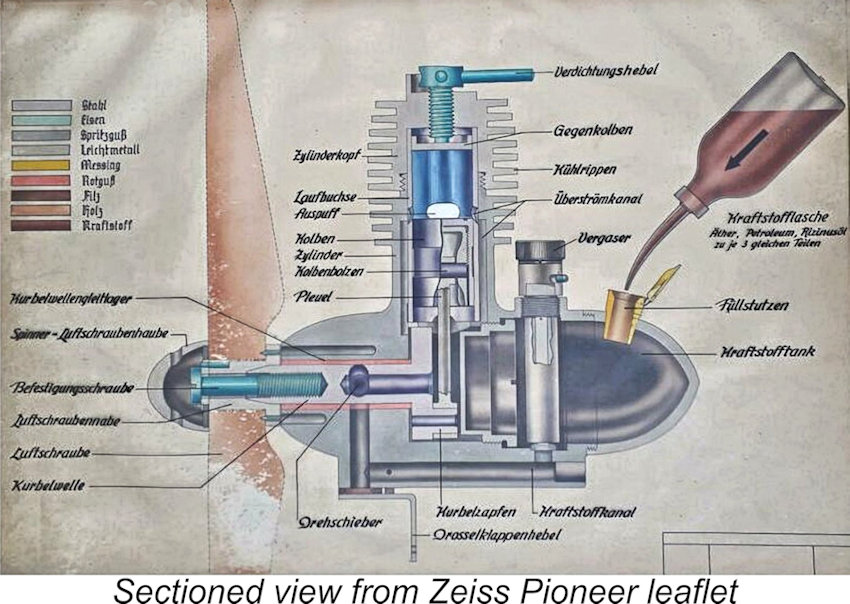
 The shaft of my example is carried in two ball-races in the familiar manner. These races are housed in an unusually massive and hence structurally stable main bearing housing. Induction is through an updraft intake tube located below the main bearing housing.
 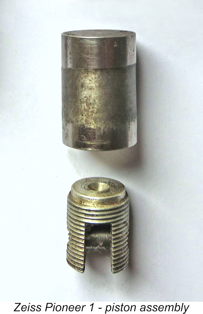 variants of the Pioneer 1 - a plain bearing version having a bronze bushing as depicted in the leaflet, and a ball-race version like the one in my possession.
 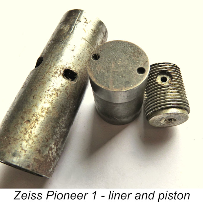 a reduction of both piston weight and crankcase volume.
 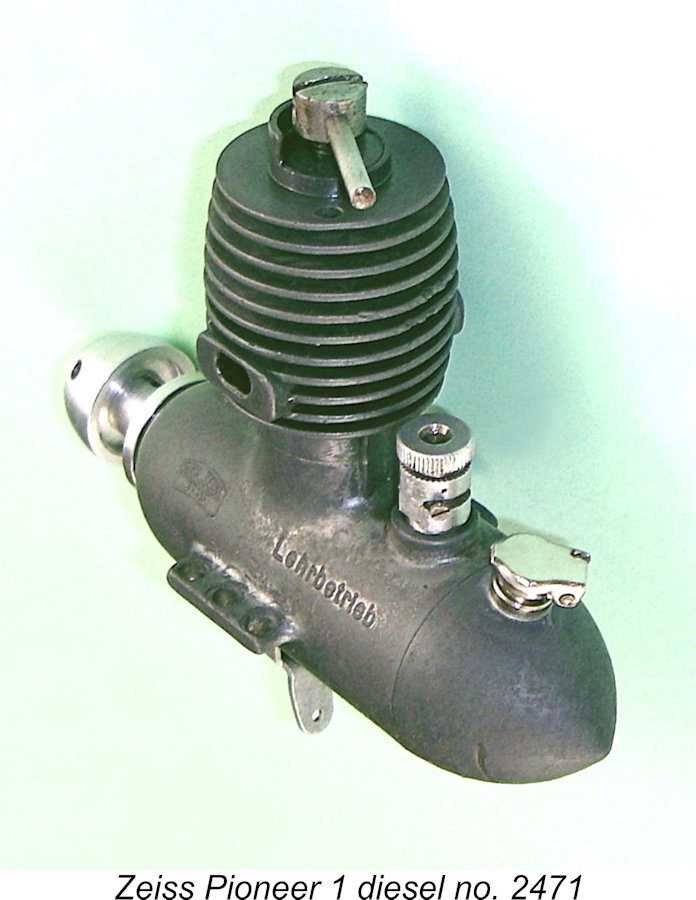 preventing the over-enthusiastic application of the comp screw by inexperienced users, although there is an operational downside, as we shall see later. To deal with the eventuality that the engine could run out of adjustment when using different props or fuels, the arm of the comp screw is of the screw-in variety, thus being amenable to installation in any of four different orientations as required.
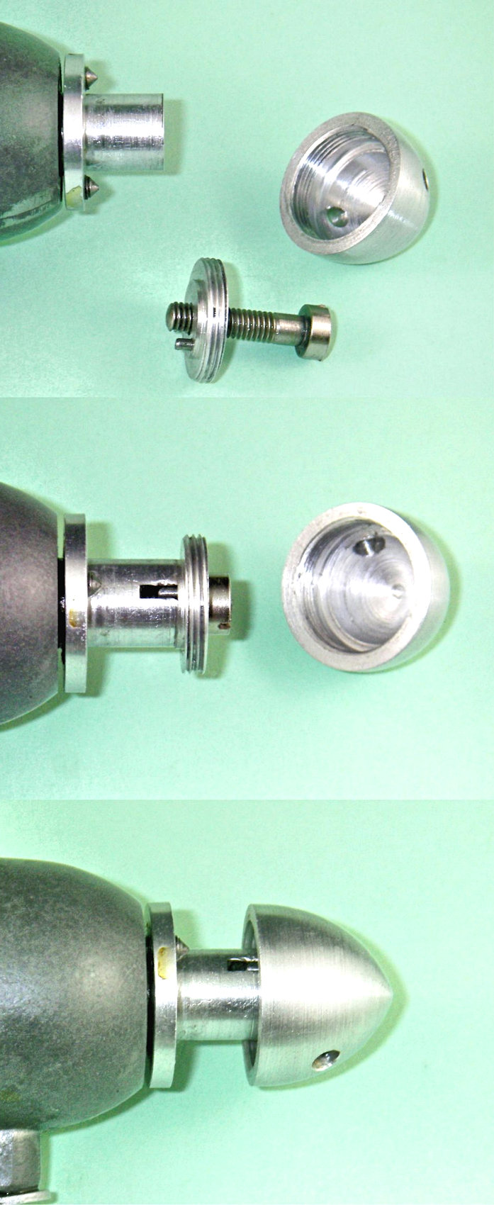 Even the means of prop mounting is quite unusual in this engine. At first glance, we seem to be dealing with a conventional assembly using a spinner nut to retain the prop. However, things are far more complex than this! The views at the left showing the components in various stages of assembly should help to clarify the following description.
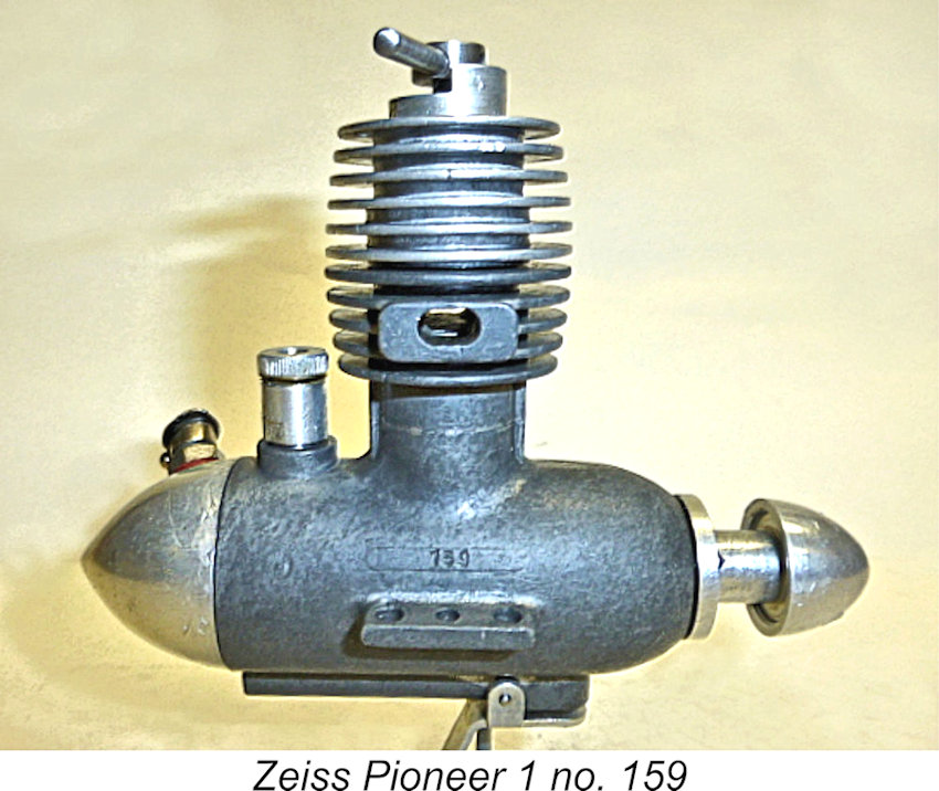 There is however another possibility - the engines could have been made in several distinct batches. In this scenario, the initial digit of the serial number would represent the batch, while the following two or three digits would represent the number of that particular engine in the batch. Thus engine number 159 would be the 59
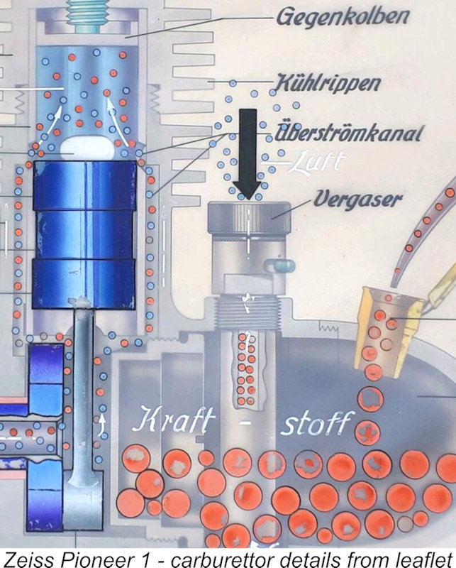 Observant readers will have noticed by now that I’ve studiously avoided any mention of the engine's fuel supply system beyond stating that it uses FRV induction allied to an integral back tank. My reticence is due to the fact that the fuel supply arrangements are by far the most interesting and unusual feature of the Pioneer. This set-up is actually unique in my experience, being a very complex form of remote mixture control. It's a little difficult to describe in words, hence fully meriting its own section of the article. Please bear with me and consult the images as I go through the following description!
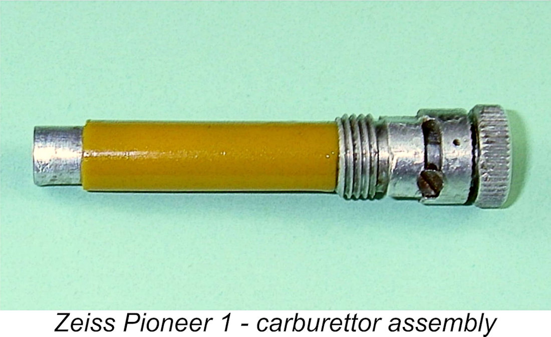 tank from top to bottom. At the latter point it feeds through a hole in the bottom of the tank into a horizontal air passage running forward beneath the crankcase to meet a conventional updraft intake located beneath the main bearing housing. We might legitimately refer to this latter feature as the secondary intake since it does have a role to play, as we shall see.
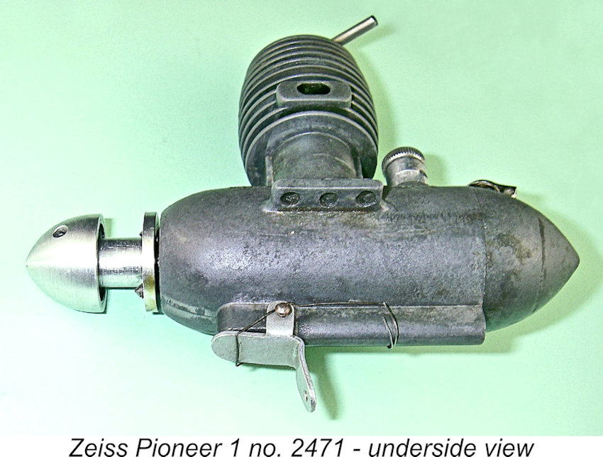 The secondary intake beneath the main bearing is open to the atmosphere in the usual way. In the absence of any intervention, this would completely destroy any suction from the primary intake at the rear. To deal with this issue, the secondary intake is closed off by a spring-loaded flap valve. With this valve closed by the action of the spring, the secondary intake no longer communicates with the outside atmosphere, the result being that the crankshaft rotary valve must necessarily draw air from the primary intake at the rear above the fuel tank through the long and rather convoluted pathway described above. However, when the flap valve is opened by the action of a timer of some sort, all suction from the rear intake is destroyed, leaving the engine sucking fresh unmixed air through the secondary intake. This would naturally stop the engine almost immediately.
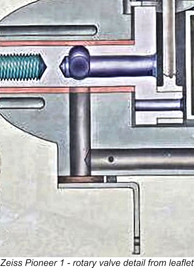 By now we should be accustomed to encountering surprises when examining this unique engine. However, you could have knocked me down with a feather when an inspection of the crankshaft valve by looking down the front intake (made more than a little tricky thanks to the presence of the flap valve) revealed that the engine is timed for opposite-hand rotation! This of course means that the engine has to be used with a pusher propeller if it is to function in conventional tractor mode. Why the designer departed from well-established convention by going this route is one of those insoluble mysteries ………... but there it is! Turning the engine over to get the transfer ports popping quickly confirmed this observation - they only pop if you turn it backwards! Oh well, at least I saved myself a lot of unproductive flicking later!
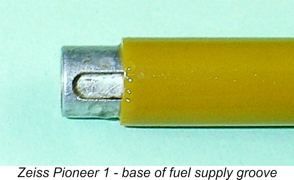
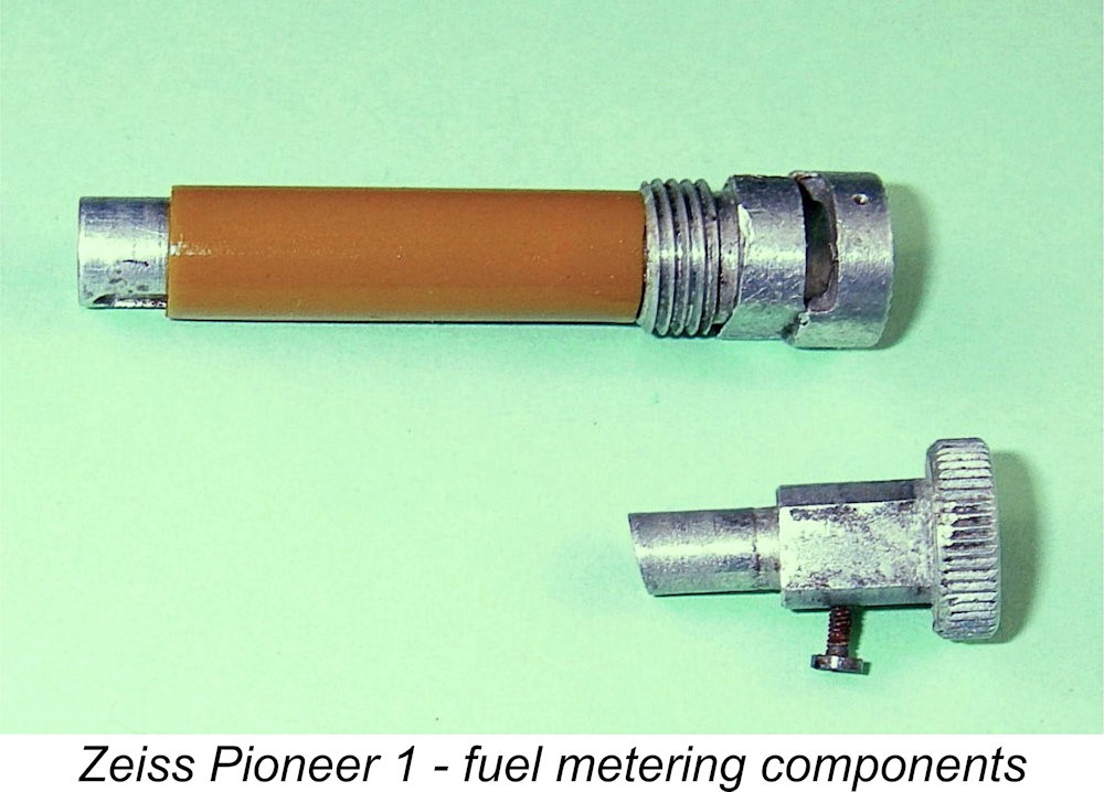 Vertical movement of the sleeve component is prevented by a very small set screw which threads into a tiny tapped hole in the sleeve and engages with an annular slot milled into the side of the induction tube. This slot allows a certain amount of rotary movement of the spigot while limiting the extent to which it can be turned in either direction. Hopefully the photographs will make all of this clear!
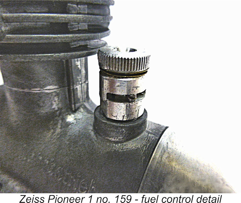 However, all was not lost! There was ample evidence to support the notion that some such device was fitted originally. The presence of two flats machined into opposite sides of the upper section of the fuel metering sleeve must surely have something to do with such a device - it's hard to account for their presence in any other way. This impression is heightened by the fact that the top edge of the induction tube beneath the mixture control knob is serrated. This implies that some form of spring (perhaps akin to a Thackeray washer) was keyed to the control sleeve using the two flats and was shaped such that its outer edge bore upon the serrations at the top of the induction tube, thus creating tension in the system and maintaining settings. I can't explain the two flats and the serrations in any other way.
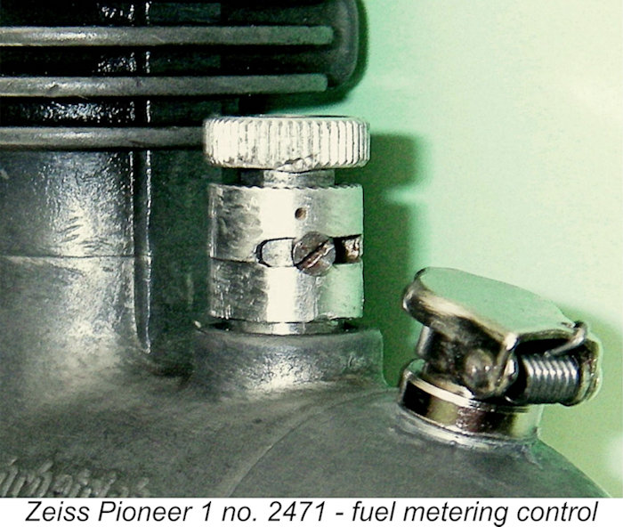
 With that caveat stated up front, on with the show! As received, the compression setting of the engine was clearly way too high - someone had screwed it down good and tight! I had to remove the control arm to unscrew the comp screw and release the contra piston. Thankfully this proved to be perfectly fitted, hence un-sticking quite easily under the influence of compression alone aided by a little oil.
 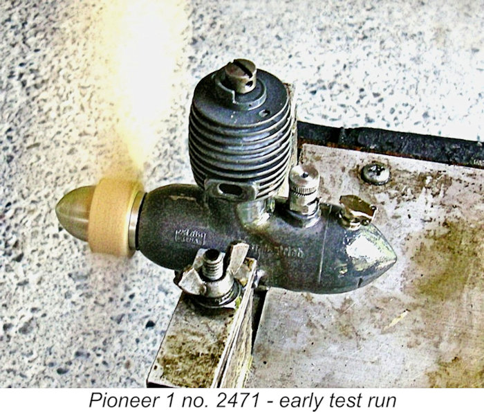 The next step was to try the effect of partially finger-choking the intake once the engine started. This was far more promising - the engine would now continue to run very smoothly, proving that fuel was being drawn from the tank through the very convoluted system described earlier. However, even after it was well warmed up, the engine continued to starve to a halt within a few seconds of the removal of the choking finger.
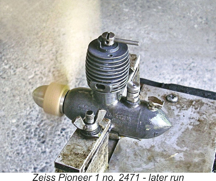 Even so, the engine was able to demonstrate that it is a very smooth runner indeed when things are stable, as well as being one of the easiest-starting diesels of my experience. It was actually quite amazing to experience a diesel which required such a "lazy" flick - more like a glow-plug motor than a diesel in that regard. No doubt the twin ball-races help in this regard. Vibration levels too were pleasantly low, especially for a long-stroke engine.
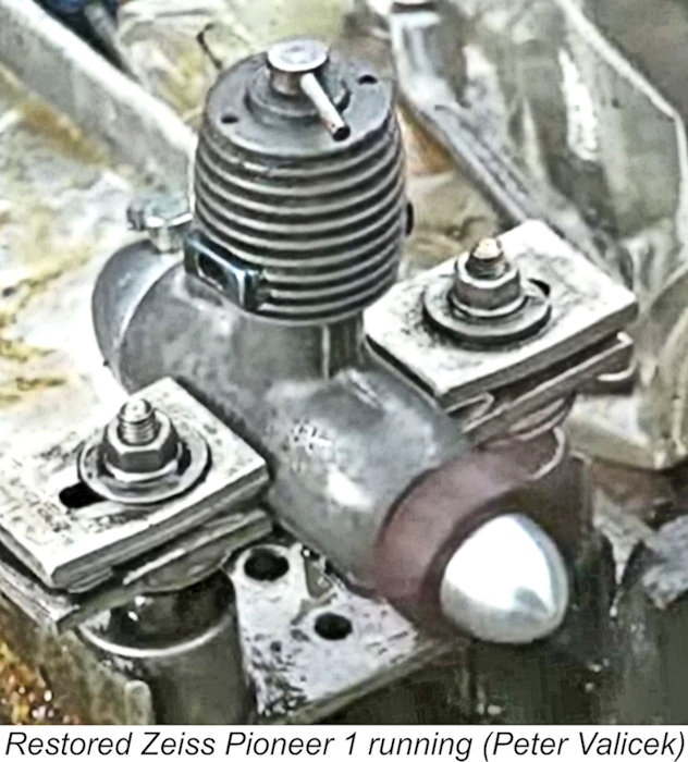
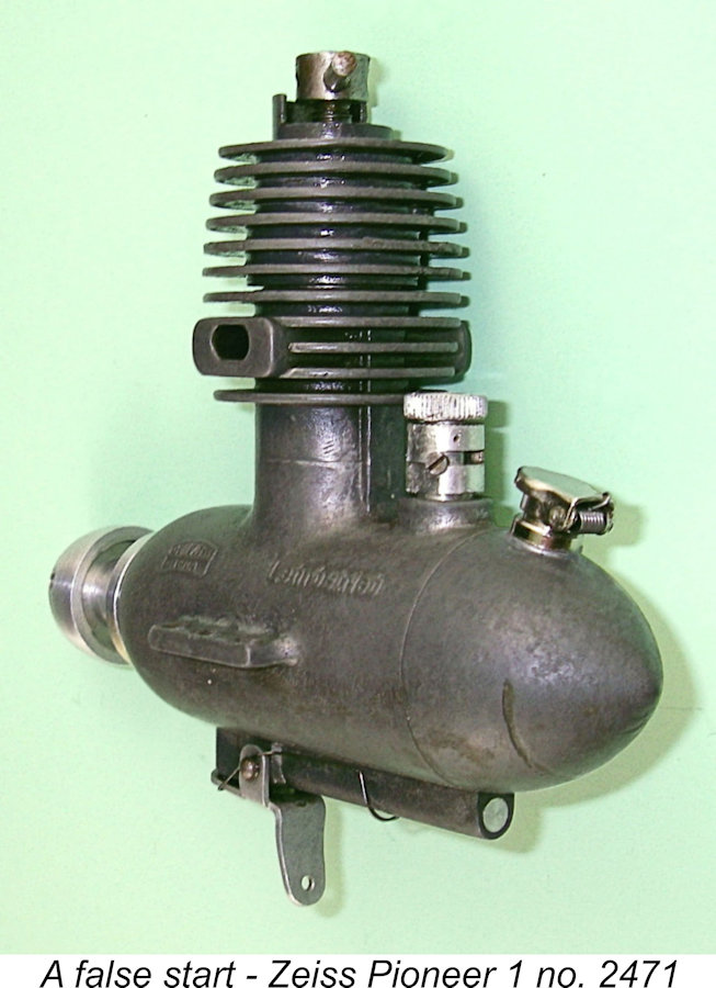 It seems clear from what little can be ascertained that the Pioneer did not remain in production for very long. The manufacture of the engine was almost certainly confined to the 1950-1952 period. The obvious inference is that the engine's combination of limited applicability and modest performance resulted in its failure to make any real impression upon the marketplace. Apart from giving them some hands-on experience in model engine manufacture, the engine represented something of a false start for its manufacturers, at least as far as their involvement with model engines was concerned.
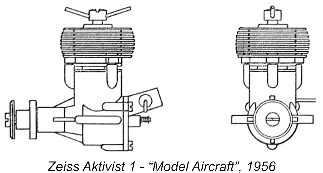 One of the engines covered in this article was a then-new 2.5 cc model from our old friends Carl Zeiss Jena which had recently appeared in the shape of the Zeiss Aktivist. It seems that production of this model must have commenced in 1955, since Chinn (writing in early 1956) was able to report that it had already appeared in no fewer than five distinct variants! The attached drawings show the very rare plain-bearing Aktivist I version.
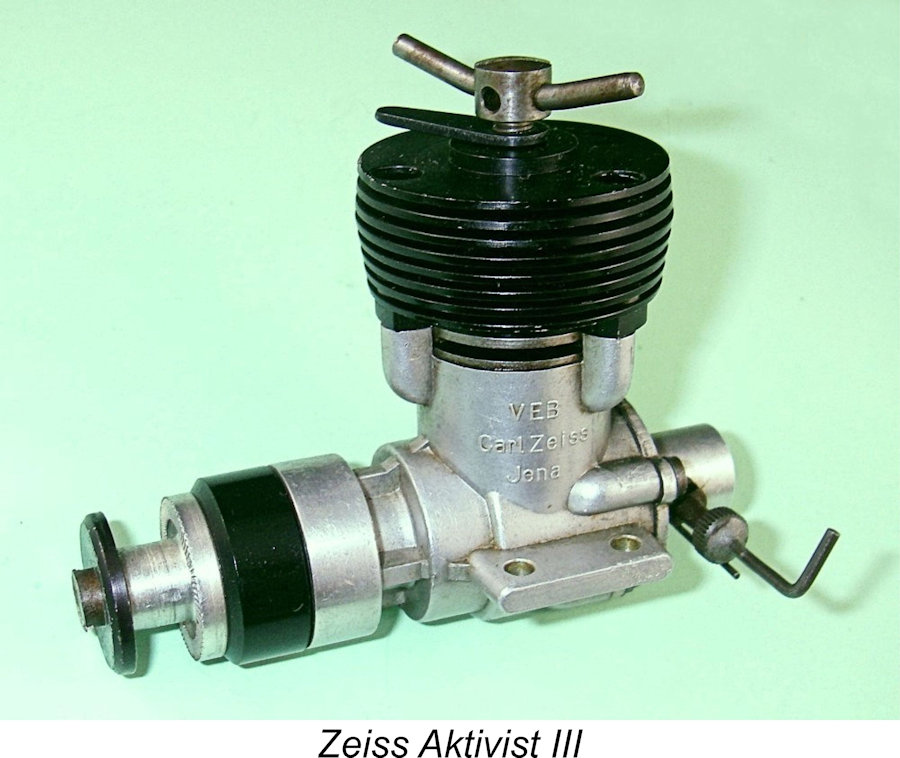 This highlights an issue which probably came to plague the staff of the Zeiss model engine manufacturing facility at Jena. It appears that once the ball got rolling, they were subject to a constant barrage of official directives from above to develop new and improved designs. In response to these directives, a sizeable number of models were produced which differed cosmetically but were functionally more or less identical, hence performing at essentially the same level. One gets the impression that the changes were made more to satisfy the company's State overseers than for any other reason! Regardless, the resulting plethora of minor variants adds a considerable challenge to Zeiss Jena model engine collecting.
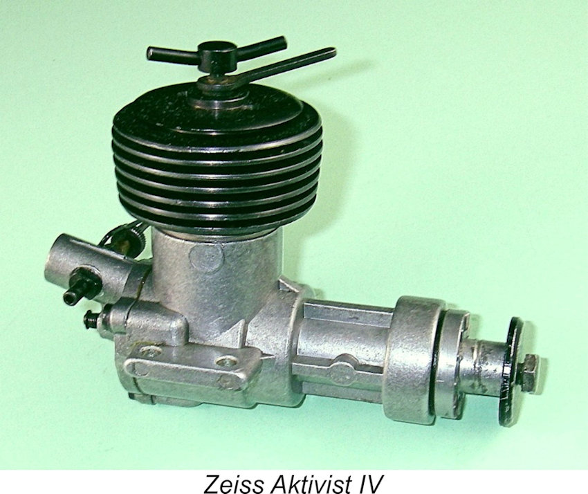 Chinn illustrated this point by noting that as of early 1956 the Aktivist 2.5 cc model had already appeared in the shape of the Aktivist I (plain bearing shaft, disc valve), the Aktivist II (twin ball-race shaft, disc valve), and the Aktivist III (twin ball-race shaft, reed valve). All of these models featured large-diameter cooling jackets which were secured by three screws engaging with tapped holes in the crankcase. There were also two other models which featured simplified cases utilizing screw-in assembly for both the cylinder and cooling jacket. These were the Aktivist IV (twin ball-raceshaft, disc valve) and the Aktivist V (twin ball-race shaft, reed valve). To further confuse matters, the latter two models
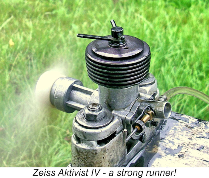
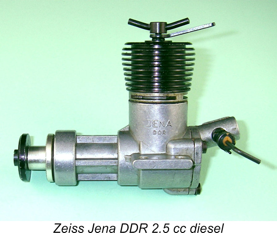 The company must have achieved a reasonable level of ongoing success in marketing these engines, since their manufacture continued at least until the late 1960's. Further minor variants of the basic Aktivist design continued to appear in both 2 cc and 2.5 cc forms under different designations. But perhaps the company's most individualistic latter-day model was their cute little 1 cc twin ball-race sideport unit, which appeared in 1960. This very unusual engine was the subject of a
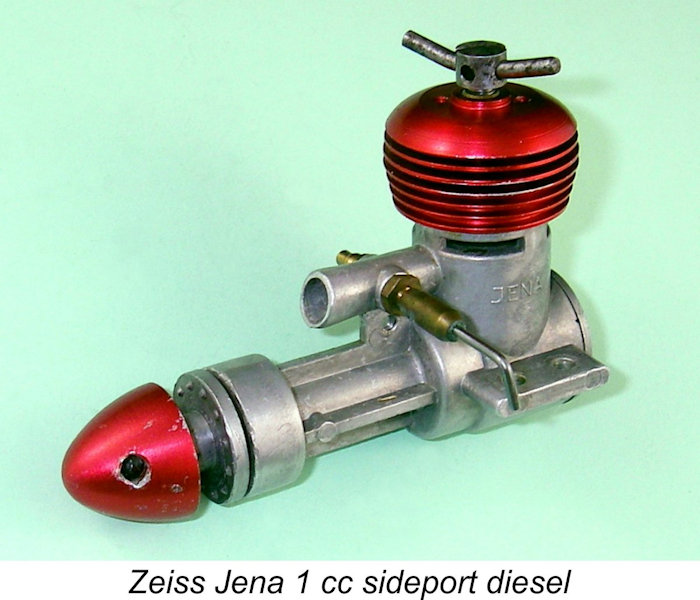
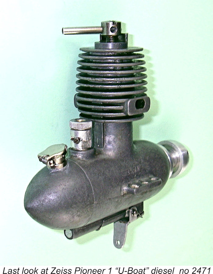
| |