
|
|
The Engines of Václav Stejskal
Before getting to grips with my subject, I must pay tribute to my two major sources of information on the Stejskal engines. As far as I can tell, these engines have never received any in-depth coverage in the English-language modelling media. Given this situation, we're forced to rely on Czech sources for our information.
I've only found two references to the Stejskal engines in the English-language model engine literature. One is found in Mike Clanford's well-known and very interesting (if often misleading) 1987 book entitled "A Pictorial A to Z of Vintage and Classic Model Airplane Engines". Clanford includes two photographs of Stejskal models but provides absolutely no relevant data. My late friend and colleague Jim Dunkin included four images of 2.5 cc Stejskal engines in his monumental work entitled "Reference Book of .15 ci/2.5 cc Model Airplane Engines". Jim did provide a little useful information in relation to these images, for which I'm in his debt. Unfortunately, the above sources provide relatively little information on the dating of the various Stejskal models. This being the case, I'm forced to admit that the dates set out in the following text must be regarded as tentative at best. If any reader can provide authoritative information regarding dates, I'd be extremely grateful. As always in such instances, it’s best to start by setting the scene in order to establish the background against which the subject engines were produced. Best get right to it! Background
Stejskal was actually a protégé of the far more Armed with the skills acquired through his association with Bušek, Stejskal soon began to undertake a good deal of engine repair and restoration work, serving the growing local power modelling community. Over a period of time, he established his own workshop. In 1954 he began to construct his own engines from scratch. From the outset, his primary goal was to produce robust and simple "consumer" engines for general use, to be sold as cheaply as possible in order to make them accessible to all. Engines Produced by Václav Stejskal The following listing of engines produced by Stejskal is undoubtedly incomplete. These are just the engines whose existence has come to my attention from the previously-listed sources – I’m 100% sure that there are others. I’d be most pleased to receive any authoritative information regarding any omissions from this list or any inaccuracies which it contains. All contributions gratefully acknowledged! According to Jiří Kalina, Stejskal’s first engine was a 3.5 cc plain bearing diesel with crankshaft front rotary valve (FRV) induction. This engine was made in very small numbers. As might be expected given Stejskal’s prior experience, it apparently showed a strong Bušek design influence – Stejskal was still feeling his way at this stage. Unfortunately, I don’t have an image of this engine to share – can any reader help? It probably looked a lot like the Buš Allbon 2.5 cc diesel illustrated above.
This neat and compact design departed from its 2.5 cc predecessor in featuring rear drum valve induction along with radial cylinder porting and a twin ball-race crankshaft. Bore and stroke of this engine were 17.0 mm and 15.4 mm respectively for a displacement of 3.49 cc. It seems almost certain that the earlier plain bearing model featured the same geometry, since these dimensions were to be maintained throughout the production life of the Stejskal 3.5 cc series.
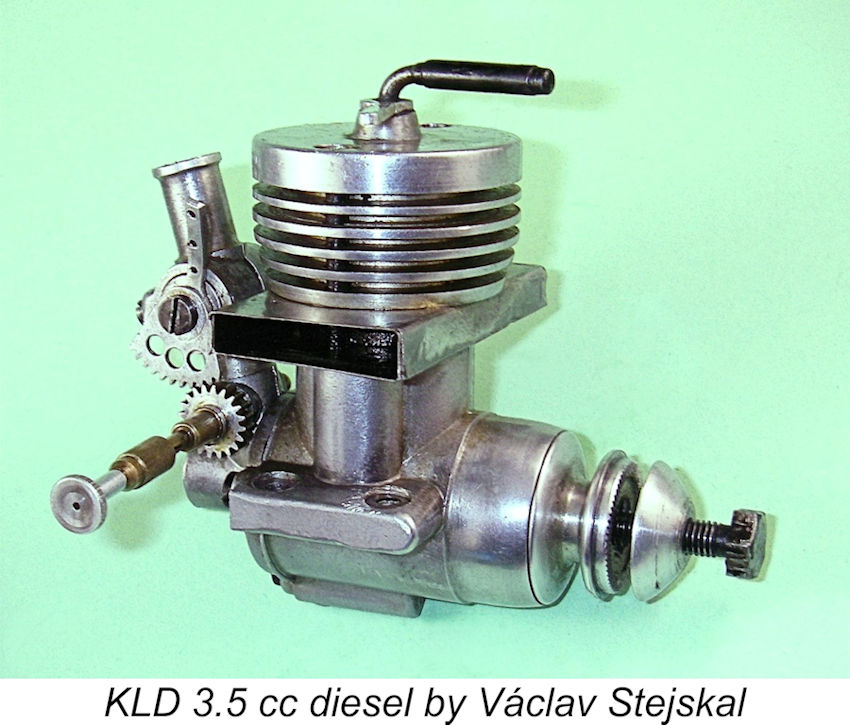
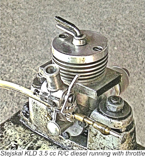
At this relatively early stage, Stejskal was already experimenting with designs for an R/C throttle which would work well with his engines. He clearly foresaw the impending growth in the prominence of R/C modelling and had no wish to be left out! It is the previously-illustrated example of what appears to be one of his early KLD 3.5 cc R/C units that is available for examination and performance evaluation. Much more of this engine below in its place.
Kalina stated that this engine was a long-stroke design having bore and stroke dimensions of 8.5 mm and 8.8 mm respectively for a displacement of 0.50 cc exactly. It weighed in at 52 gm (1.84 ounces). Kalina claimed that it would turn a 145/100 mm airscrew (approximately 6x4) airscrew at 10,000 RPM.
The accompanying December 1965 advertisement located by Maris Dislers proves that when the MIKRO trade-name was adopted, the original KLD 3.5 cc diesel with its complex geared throttle was still in production at some level. Kalina stated that it reportedly turned a 250/120 mm (approximately 10x5) airscrew at speeds within a range of 2,500 – 12,500 RPM. My illustrated example weighs in at a checked 227 gm - a little heavier than the advertising claim.
the MIKRO name of which I’m presently aware were an updated version of the 3.5 cc KLD R/C diesel and a 2.5 cc KLD model based upon the same castings. These units appeared at some point in time after 1964. The design was basically similar to that of the original 3.5 cc KLD of 1957, but the sheet metal exhaust stack fitting had now given way to a cast exhaust collector which discharged to one side or the other. This was arranged to accommodate a venturi silencer which rather dwarfed the engine! The throttle used with these revised KLD models appeared to be a more or less conventional unit – the complexity of the throttle used on the R/C version of the previously-cited KLD unit of 1957 had evidently made it uneconomic to continue to produce that design. More of that fitting below …………
Interestingly enough, the geared-throttle R/C version of the original drum-valve KLD 3.5 cc diesel continued to be The most interesting aspect of these engines' design was the cylinder porting – they featured twin rear-facing exhausts in place of the former radial disposition. Jim Dunkin noted that the engine also featured two internal bypass/transfer flutes formed in the cylinder wall at the front. In effect, the cylinder porting of these engines was pretty much identical in concept to that seen 17 years earlier in the E.D. Mk. 1 Series 1 Bee of 1948. Jim also confirmed that the 2.5 cc version at least was offered in R/C configuration - perhaps they all were.
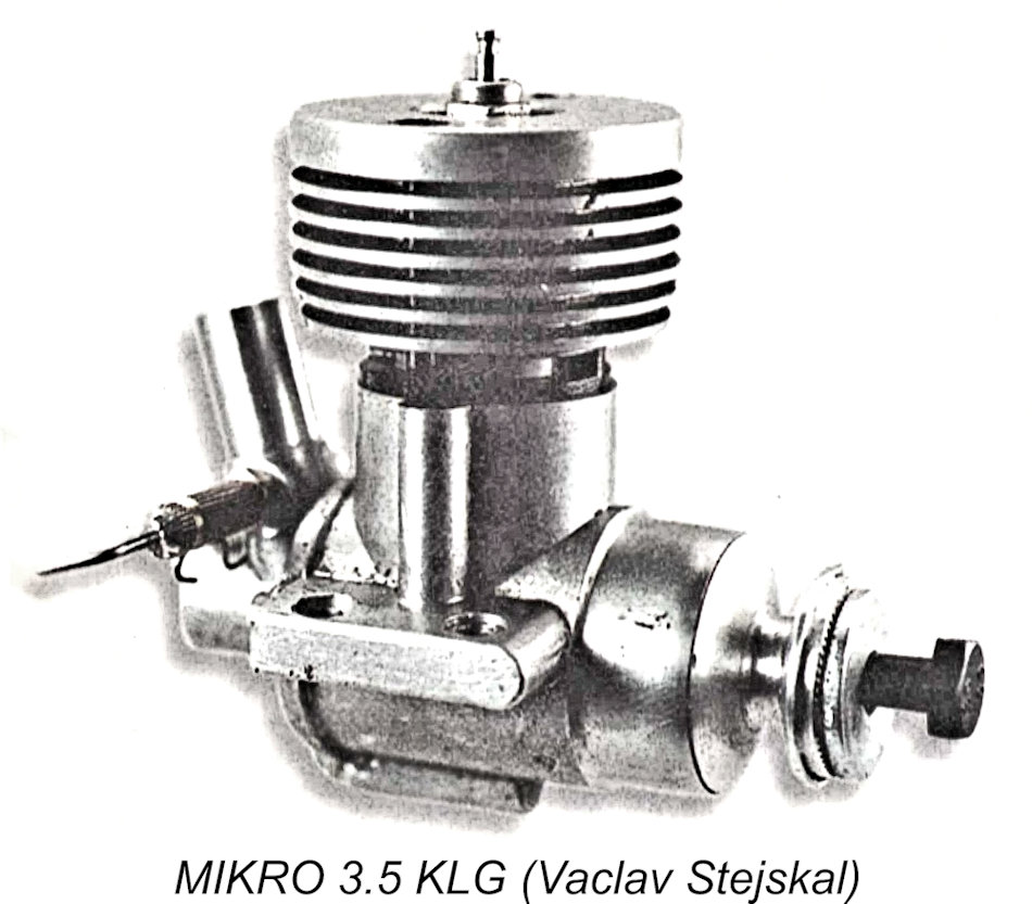
The last media reference to Stejsakl's engines of whch I'm aware is an article by Stejskal himelf which appeared in the October 1999 issue of the Czech model magazine "Modelář a Modely". I'm grateful to Milan Porkristl for drawing my attention to this article, in which Stejskal described a glow-plug version of the MIKRO 3.5 cc ball-race model which he designated as the MIKRO 3.5 KLG. Milan advised that the term KLG stands for "Kuličková Ložiska Glow" (Ball Bearing Glow). He believed that this was the last MIKRO model to appear. Interestingly enough, Stejskal was serving as the magazine's engine tester at this time - a test of the MVVS 7.5 cc ABC marine engine by Stejskal appeared in the same issue of the magazine. The Original KLD 3.5 cc Diesel Described
For convenience, I’ll repeat the engine’s vital statistics here. This radially-ported design features rear drum valve induction along with a twin ball-race crankshaft. Bore and stroke are 17.0 mm and 15.4 mm respectively for a displacement of 3.49 cc. The aero version of this design was supplied with a rather flimsy sheet metal exhaust manifold having outlets at both sides. Cited weight of this version of the engine was 220 gm (7.76 ounces). My illustrated R/C example weighs in at a checked 227 gm (8.00 ounces) - a lot of weight for a 3.5 cc diesel. It bears no serial number or any other marks of identification. As a rule, I don't dismantle rare engines which have clearly been used and are seemingly well-settled. However, in this case I had to make an exception because the engine had apparently been stored for decades in a completely gummed-up state. Moreover, the solidified lubricant was unusually persistent - even the usual applications of heat, solvent and after-run oil couldn't touch it. It was almost as if a previous owner had shot it full of glue!! So the engine had to come apart for a complete clean-out and rebuild. It was as well that I did this, because the gum proved to be so unusually hard and thick that it appeared to be immune from the action of solvents. The gum had resulted in oil access to the main bearings being severely compromised, while the ball-races themselves were chock full of hardened residues. Much of this had to be removed by physical means, after which the solvents became more effective in dealing with the residue. I wish that more people would store their engines properly! I also found that the hollow 4 mm diameter steel gudgeon pin was considerably shorter than the bore. This clearly implied that the pin was designed to have end pads fitted to protect the bore. These had apparently been overlooked by a previous owner when dismantling the engine "just for a look" - a depressingly common occurence. The bore already showed some early signs of unwanted wear resulting from this omission, although it had not progressed to a significant extent. I made replacements from hard brass. Aggravating though it was to have to undertake a complete rebuild, this necessary interference had one positive result - it enabled me to describe the engine far more completely! Upon reassembly, things felt really good - the engine was clearly all ready to run once more.
The engine is built around a nicely-executed gravity die-casting. The drop-in steel cylinder liner is marked at the front to ensure its reassembly in the same orientation in the event that a dismantling becomes necessary, as in this case. It is provided with a substantial finned light alloy cooling jacket which also incorporates the cylinder head. In common with many Czech Cylinder porting is more or less conventional. There are four radially-disposed sawn exhaust slits with four internally-formed bypass/transfer flutes of generous size which terminate just below the exhausts. The downside of this arrangement is that it imposes a fairly lengthy blow-down period given the impossibility of providing any overlap between the exhaust and transfer ports. In order to provide a reasonable transfer period, it becomes necessary to open the exhaust ports relatively early. The exhaust ports of the KLD 3.5 open at only around 105 degrees after Top Dead Centre, The flat-topped cast iron piston is machined internally for minimum weight while retaining substantial bosses which provide excellent support for the 4 mm diameter gudgeon pin. The nicely-made conrod is fully machined from barstock. It has a commendably long small end bearing. It drives the one-piece steel crankshaft through a 5 mm diameter crankpin which is mounted on a full-disc crankweb having a small counterbalance opposite the crankpin.
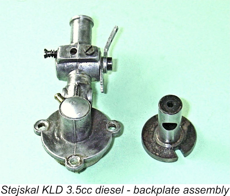
The backplate is secured to the crankcase with three machine screws. It is an extremely complex die-casting which incorporates the drum valve housing, the intake venturi and the throttle body in a single component. The steel drum valve itself is driven by a small-diameter extension of the crankpin which engages with a slot in the drum's forward driving disc. The drum's journal Like the transfer period, induction timing is quite conservative. The induction phase opens at an unusually late 80 degrees after Bottom Dead Centre, some 30 degrees after the transfer ports have closed. The system remains open until around 30 degrees after Top Dead Centre for a total induction period of only 130 degrees. It appears that high operating speeds were not envisioned for this engine ........ The drum valve bearing is reamed right through the backplate casting, being sealed at the rear I’ve saved the best for last - the throttle on this example is fascinating! There’s no question in my mind that it is original equipment – the fact that it’s built up around a casting which is integral with the backplate precludes an owner intervention. The assembly incorporates two distinct elements – a conventional rotary barrel-type air restrictor at the top and a completely separate spraybar located independently well downstream of the restrictor barrel. The barrel restrictor is retained in its bore by a small snub-ended screw which engages with a groove in the surface of the drum. The restrictor is provided with an adjustable air bleed. The spraybar thread is 3 mm, but the component is waisted to a diameter of only 2 mm over the portion which transects the 4.8 mm dia. venturi throat.
The needle itself threads not onto the spraybar but onto the outer spigot of the gear section, so it turns with the gear but can be adjusted independently from the gear. The effect is that there are two distinct ways of adjusting the mixture – either by turning the gear together with the needle, or by holding the gear stationary while turning the needle relative to the gear. Either mode moves the needle in or out.
The rationale for this system is probably based upon consideration of the relative locations of the restrictor barrel and the spraybar. Reducing the intake area using the barrel restrictor is akin to partially choking the intake. It will cause an increase in negative manifold pressure downstream of the restriction, where the spraybar is located. This would cause an unwarranted richening of the fuel mixture – less air but more fuel. The associated leaning-out of the needle is presumably intended to offset this effect to some degree. The idea is probably to promote more even running at lower throttle settings. The air bleed associated with the barrel restrictor provides further flexibility in terms of low-speed adjustment. This throttle design appears to be unwarrantably complex compared to the more conventional units which were generally used and which worked very well. It would have been rather expensive to produce in series. However, it must be recalled that the development of R/C throttles for model engines was still in its infancy in 1957. I suspect that this device was an experiment by Václav Stejskal which was tried and found to be not worth pursuing in the long term – his later engines appear to have conventional throttles. Still, other examples with this type of throttle very likely exist. An idea of this originality certainly merits testing! So without further ado, on to the test bench! The 1957 KLD 3.5 cc Diesel on Test One positive attribute of the throttle design described above is the fact that it's very easily disabled - no adaptors required! All one has to do is loosen the small screw that retains the upper throttle barrel restrictor in its housing and withdraw the barrel with its control arm and toothed segment still attached. The needle valve still works just fine - the engine becomes an un-throttled unit drawing air from the interior of the now-open throttle barrel cavity. To determine the engine's performance potential, I elected to run my initial tests with the throttle disabled in this manner. Following the development of a representative set of prop/RPM figures, it was my intention to re-assemble the throttle and test its effectiveness using whatever prop seemed to be best matched to the engine's measured performance characteristics.
With the barrel restrictor removed, it seemed best to screw the geared segment of the needle valve all the way in and then make adjustments in the normal way using the outer control. This approach worked extremely well. I set the needle to what seemed to me to be a reasonable setting, set the compression by feel, injected a few drops of fuel down the intake, administered a small exhaust prime and then got down to it. The engine started firing immediately, and a little more compression soon had it running.
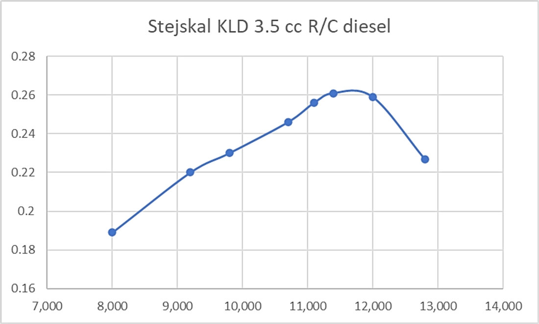
As expected, the contra-piston was inclined to run back slowly in this relatively cool rich operating condition, making the compression locking lever a very welcome feature. After a period of shake-down running, I leaned it out all the way to get a speed reading for the Taipan 10x6 prop. At full lean, the contra piston became completely stable - the locking lever was no longer required. Running in this condition was notably smooth, with no tendency to sag. A certain level of vibration was detectable, but actually somewhat less than I had been expecting. It was apparent that the 10x6 airscrew was at the more heavily-loaded end of things - hardly surprising for a 3.5 cc engine. I therefore tried a succession of progressively lighter loads, with the following results.
As can be seen, the KLD 3.5 cc diesel developed a peak output of around 0.262 BHP @ 11,500 RPM. Not perhaps a stellar performance for a 3.5 cc diesel, but this was 1957, remember, while this engine was never intended to be a competition powerplant. The engine showed itself to be a very smooth runner with a more than adequate performance to fly a typical mid-sized R/C sport or scale model, which is what it was designed to do. It also handled very well. A 9x6 or 10x4 airscrew would seem to suit it perfectly for flying purposes. This left the question of how well the unusually complex throttle worked. I re-installed the barrel with its gear segment and control arm, making the engine complete once more. I elected to try the engine in this configuration with the APC 9x6, since that appeared to be the ideal flight prop for this engine.
With the engine well warmed up, I set the needle very carefully for optimum performance at full throttle and then tried closing the throttle progressively. As the barrel restricted air entry to an increasing extent, the gearing turned the needle in to restrict the fuel intake as well. This appeared to be quite effective - although it slowed down progressively, the engine continued to run absolutely smoothly, never missing a beat. However, all was not perfect - at around 4,000 RPM the engine sudenly stopped! Clearly the carburettor had reached the limit of its ability to draw fuel from the tank. Up to that point, running had been absolutely smooth and mis-free. I found that I could help matters by closing the air bleed a little, but I never succeeded in getting a dependable low-speed setting below 3,800 RPM using this prop. Of course, I'm not an R/C guy! Perhaps someone with a better grasp of diesel speed control systems would have done better. All that I can say is that I was very impressed by the highly progressive control which this throttle provided, with dead smooth running throughout the practicable speed range. Summary and Conclusion As stated earlier, the Stejskal engines appear to be very little known outside of their native Czechia. Until the test example of the 3.5 cc KLD R/C diesel came my way from a friend in the USA, I'd never seen one in the metal - in fact, I had only a very hazy idea regarding who Václav Stejskal was! I knew his name, but little else - the engines that he designed and produced were a closed book to me until the arrival of the test engine prompted a focused seach for information. This relative obscurity is undeserved, because the test engine proves that Stejskal was a very competent artisan who understood his business very well and was perfectly able to produce very usable model diesels to a more than acceptable standard. Moreover, although much of his early work seems to have been highly derivative, his designs for the KLD series and the Standart models display a healthy dose of original thinking. This is a man who is well deserving of taking his place on the honor roll of Czech model engine designers and makers of the classic era! I hope that this article has done something to remedy his previous neglect! ________________________ Article © Adrian C. Duncan, Coquitlam, British Columbia, Canada First published May 2025 |
||
 In this article, I’ll present a capsule review of the model engines produced in relatively small numbers by one of Czechoslovakia’s less-prominent manufacturers - Václav Stejskal of Prague, Czechoslovakia (as Czechia was then). I’ll also share the results of a test of one of his more interesting products – the 3.5 cc KLD R/C diesel. This very distinctive and well-made unit features an R/C throttle of a very advanced and seemingly experimental design which is unique in my personal experience. I'll back this statement up in due course ..........
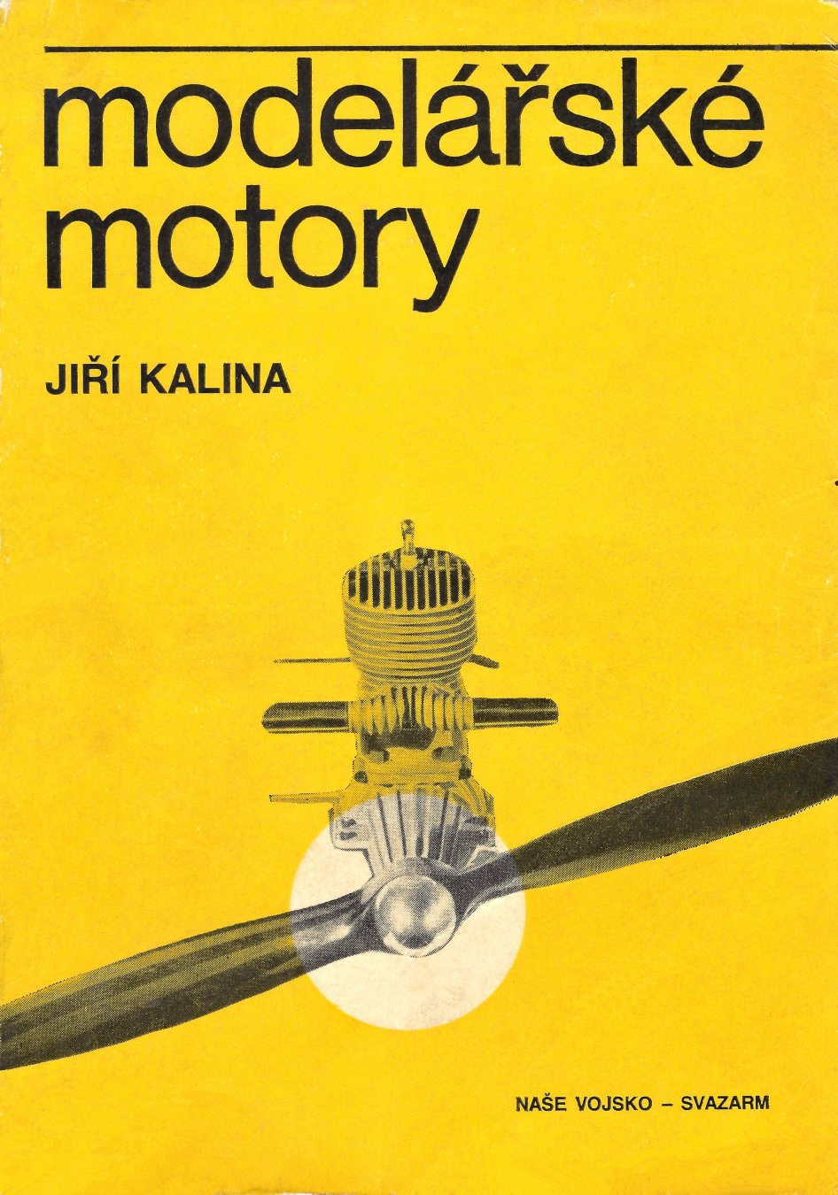

 The former nation of Czechoslovakia (now divided into the separate countries of
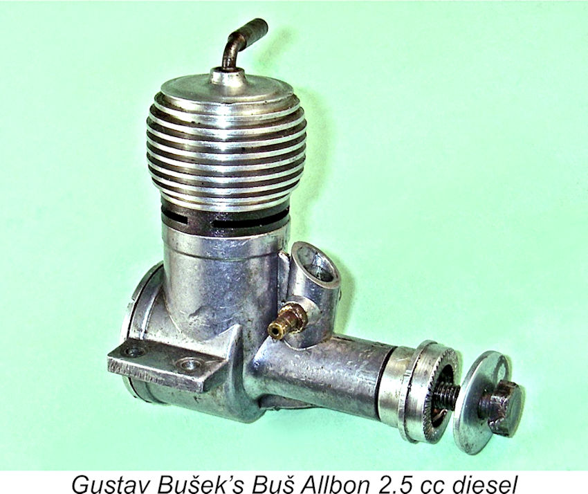
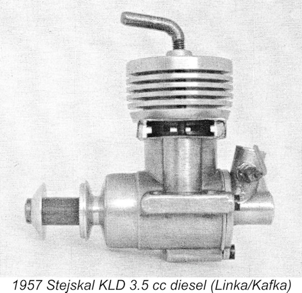 By 1957 Stejskal was ready to apply his own design stamp to his engines. His next model was a 3.5 cc unit which he designated the KLD 3.5. MP Jet company founder Milan Porkristl was kind enough to contact me to advise that these initials stood for ""Kuličková Ložiska Diesel" (Ball Bearing Diesel).
 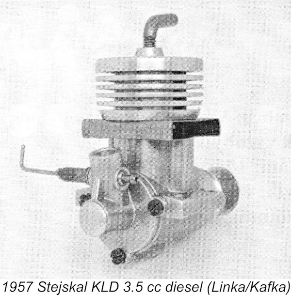 The aero version of this design was supplied with a rather flimsy sheet metal exhaust manifold having outlets at both sides, very similar in concept to the accessory which had been available previously for the
 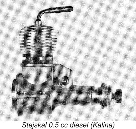 At this stage, Stejskal was continuing to market his engines under his own name. While presumably continuing to develop and manufacture the 3.5 cc KLD model (and possibly the plain bearing unit as well), Stejskal now began to expand his range, introducing smaller diesels of conventional design having displacements of 0.5 cc and 0.8 cc. Kalina provided an image of one of Stejskal’s 0.5 cc diesels from this period - a reproduction of this image is attached here. It was a simple plain bearing FRV diesel featuring radial cylinder porting – presumably the 0.8 cc model was similarly configured. The Bušek influence is readily apparent.
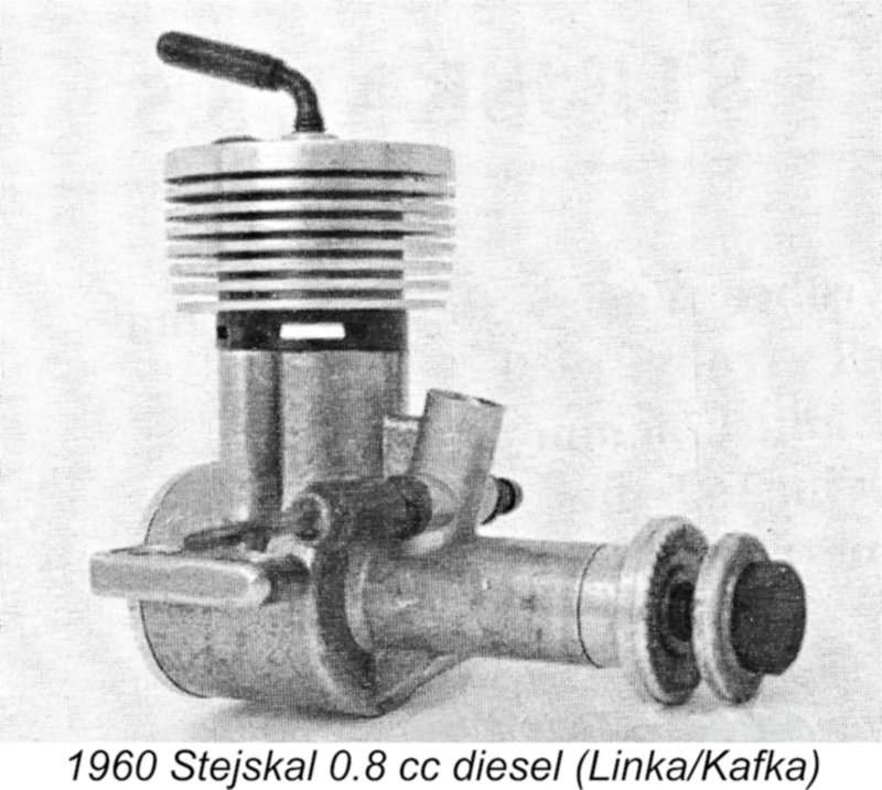 By 1960 Stejskal was apparently in full production with a range of engines in different displacement categories. I have no definite information regarding the full range at this point in time, but Linka/Kafka provided images of a 0.8 cc plain bearing radially-ported model dating from this period, while Jim Dunkin confirmed the existence of a more or less identically-designed 2.5 cc version at this date. It seems safe to assume that there were others. Based upon the admittely limited advertising record, production of the 3.5 cc KLD model was evidently continuing at this stage.
 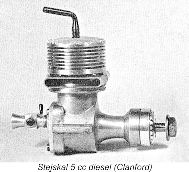 Mike Clanford included an image of what he claimed to be a MIKRO 5 cc twin ball-race disc valve diesel for which he cited a date of 1960. This date precedes that on which Stejskal adopted the MIKRO trade-name - Clanford may have been unaware of this. His book is both entertaining and useful, but it is quite unreliable when it comes to dates and model identification - Clanford did little or no original research. The engine bears a strong resemblance to the 5 cc Miles Special marketed by E.D. on behalf of Basil Miles.
 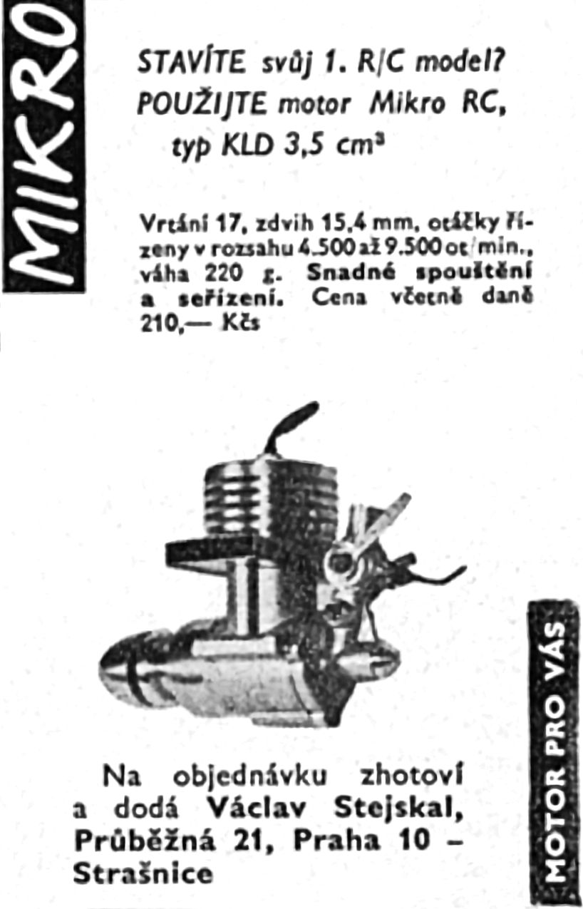 According to Kalina, it was in 1964 that Stejskal finally adopted a trade-name for his engines. He chose the name MIKRO, thereby reprising the name applied earlier by Kai Nielsen of Copenhagen, Denmark to his various model engines. However, the
 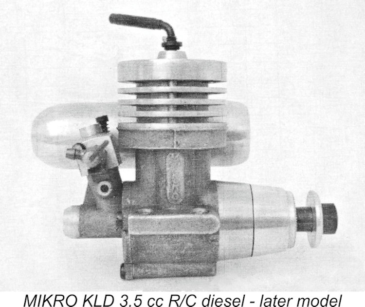 For some reason, the MIKRO name did not appear on this version of the KLD. The first such units to display
 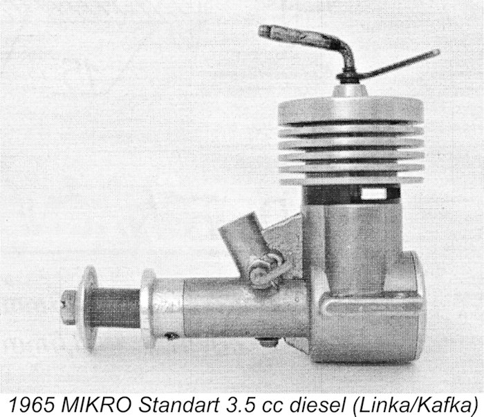 In 1965 Stejskal launched his MIKRO Standart (Standard) line of diesels. These units were all constructed at different scales to a common design. They were produced in displacements of 1.5 cc (bore/stroke 13/12 mm, weight 95 gm), 2.5 cc (bore/stroke 15/14 mm, weight 95 gm) and 3.5 cc (bore/stroke 17/15.4 mm, weight 245 gm) displacements. All models were plain bearing engines featuring FRV induction.
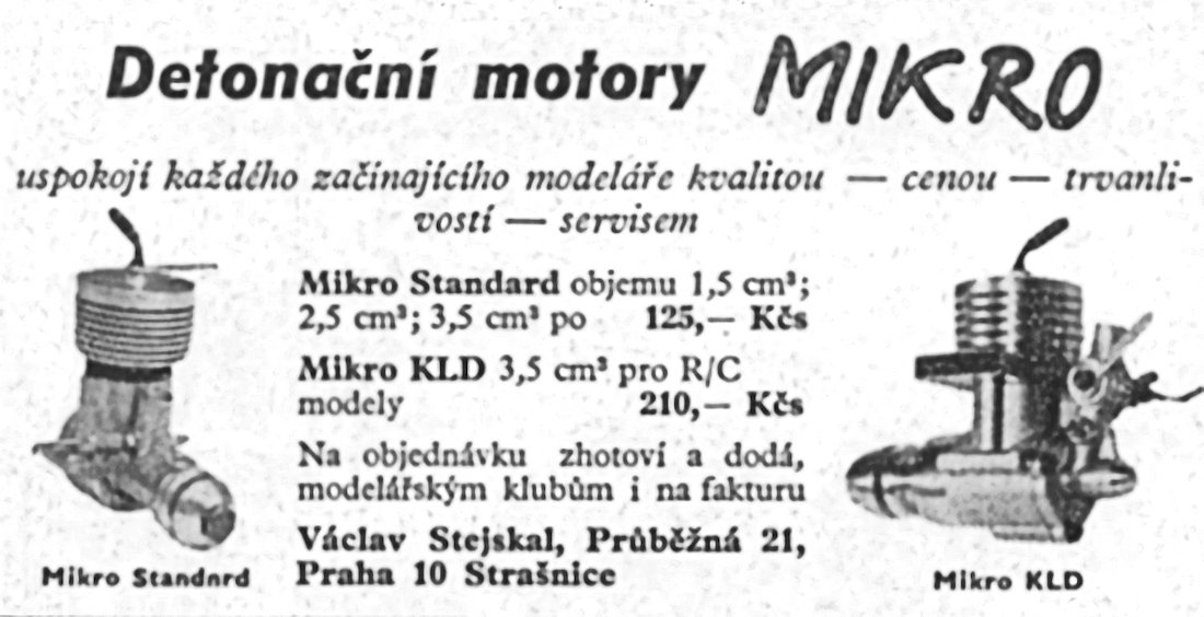
 The MIKRO Standart series of 1965 are the last engines made by Stejskal to receive a mention from either Jiří Kalina or Jiří Linka/Jan Kafka. However, Stejskal continued to produce engines long after this date. They were still being advertised as of April 1969 - Maris Dislers found an advertisement of that date to confirm this statement. Stejskal actually remained in the model engine business at least through the 1980's and 1990's - Maris actually purchased a new engine directly from him in 1990.
 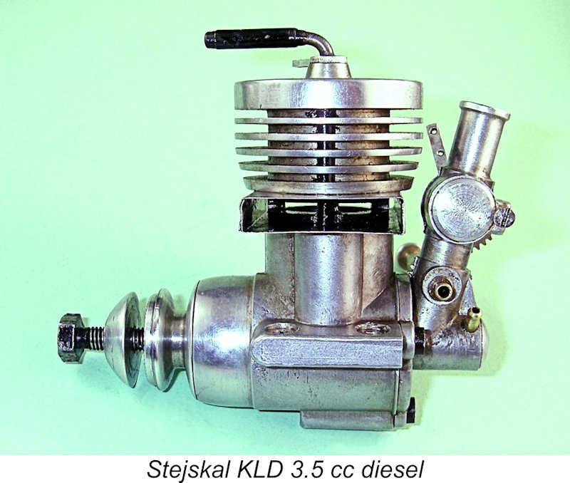 The Stejskal engines appear to be somewhat rarely encountered outside of their native region. The illustrated R/C version of the original 3.5 cc KLD diesel of 1957 is the sole example of Stejskal’s work which is on hand for review and test. So let's take full advantage of this opportunity!
 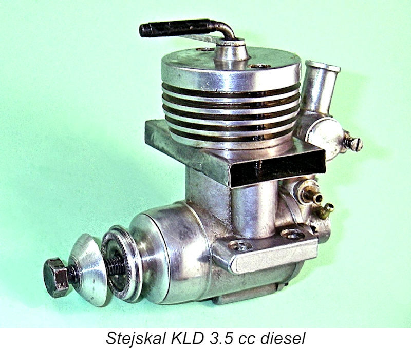 But that was for later - for now, let's focus on the description. This example is is excellent mechanical and cosmetic condition, although it has clearly seen some use in the past. The overall comment may be made quite objectively that the quality of the engine's construction is well up to the best contemporary standards for commercial diesels, especially inside where it really counts.
 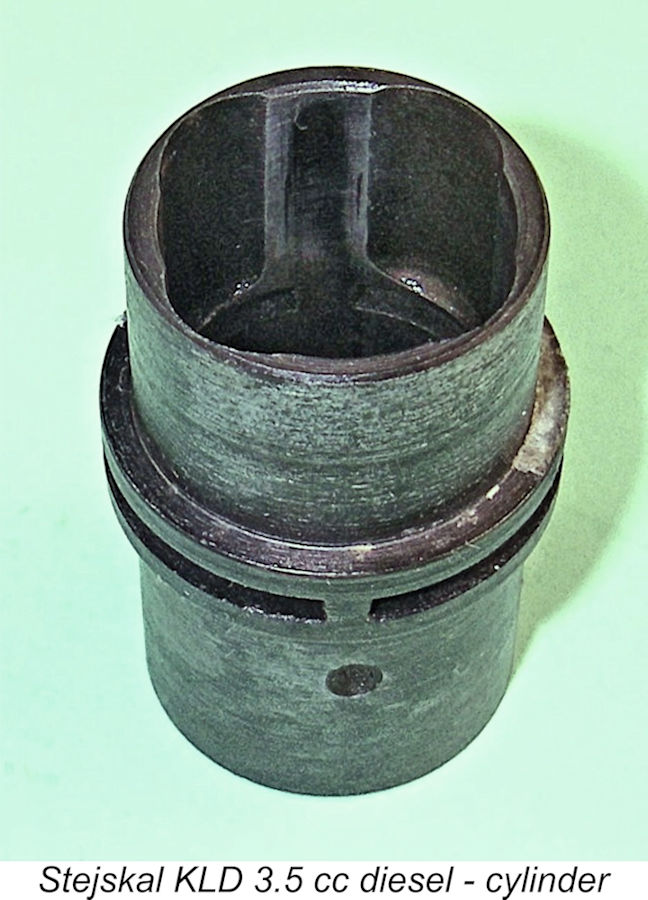 engines of the 1950's, the contra piston is also of light alloy. The entire assembly is secured to the crankcase with only two long screws which pass through the head, cooling jacket and exhaust manifold to engage with tapped holes in the upper crankcase.
 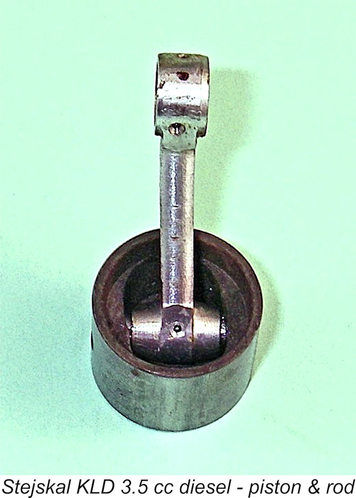 giving an exhaust period of some 150 degrees, which almost certainly wastes some of the potential power stroke. Even with this rather early opening for what does not appear to be a high-speed engine, the transfer ports don't open until around 130 degrees after Top Dead Centre for a somewhat restrictive transfer period of only 100 degrees.
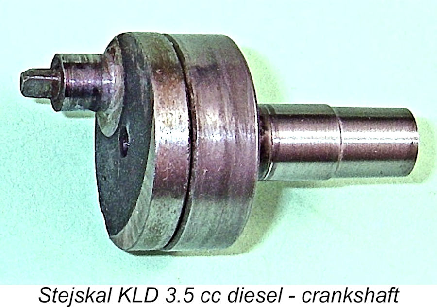
 diameter is 9 mm, with a 6 mm diameter central gas passage. The induction port in the drum surface is a simple round hole of surprisingly modest size. Given the fact that the drum is not subject to operational forces, a more efficient induction port could undoubtedly have been provided.
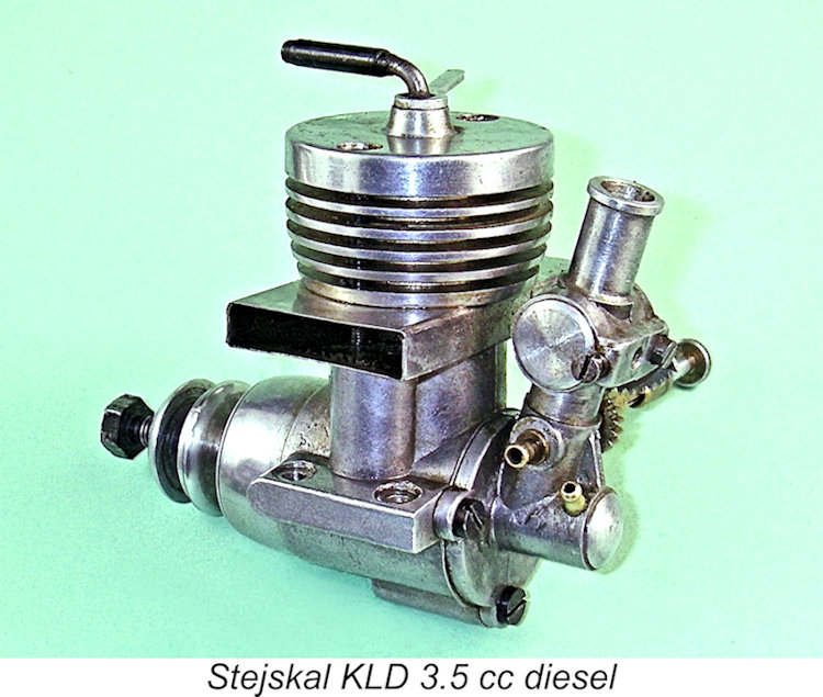
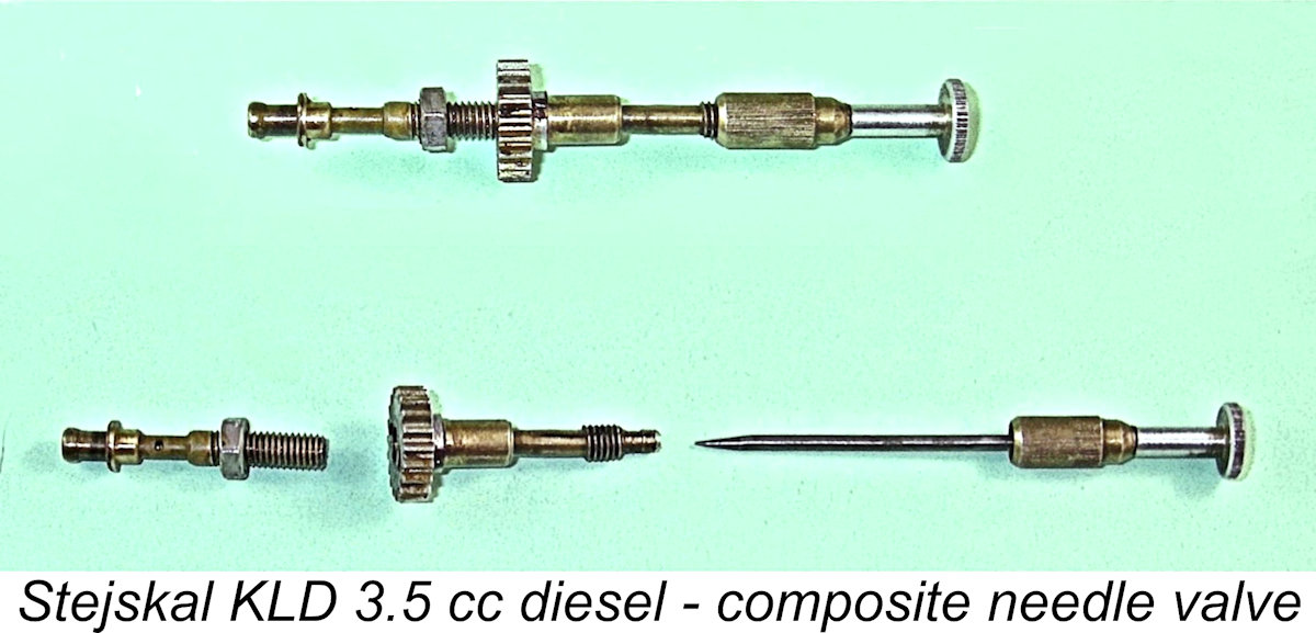 The component with the circular gear threads onto the spraybar, being linked to the barrel restrictor by the engaged toothed plate segment. It is thus constrained to rotate on its thread with the barrel restrictor, albeit in the opposite direction and at a higher rate of angular displacement.
 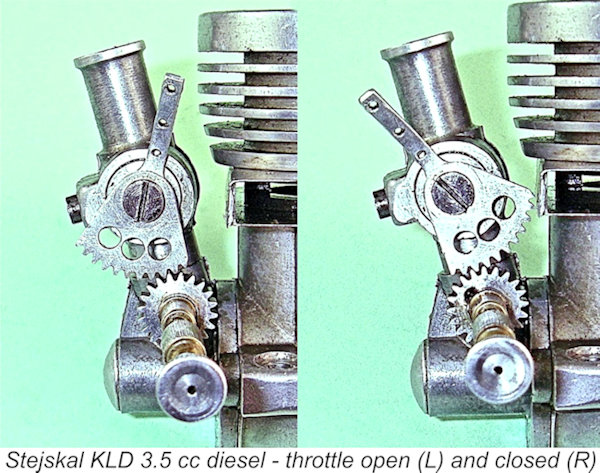 The effect of restricting the air passage by pulling the throttle arm towards the rear is to rotate the circular gear clockwise on the spraybar thread, slightly leaning out the mixture since the needle follows the gear. The idea seems to be that with the throttle held wide open (gear stationary), the needle is set for best running. When the throttle is closed, the gear kicks in and rotates clockwise on the thread by about
 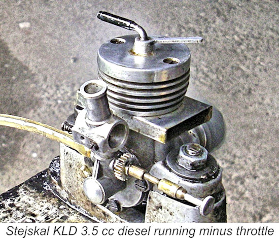 Set up in the test stand, the engine felt really good, turning extremely freely in its ball races. I found that the aluminium alloy contra piston was a little on the slack side when cold, but that's normal with such contra pistons - they usually expand to a very secure fit once the engine is running. I decided to begin with a Taipan 10x6 prop and see where things went from there.
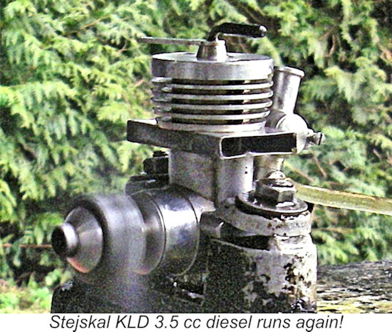
 Handling was unaffected by the re-activation of the throttle - the engine started very promptly at full throttle following the administration of an exhaust prime. I wouldn't characterize this engine as a one or two flick starter, but it never took long. I quickly determined that the installation of the throttle hadn't affected the engine's performance at all - it still turned the 9x6 prop at 9,800 RPM.
 | |