
|
|
The Early Years at MVVS – the Classic Glow-plug Models
The MVVS company of Brno in the former Czechoslovakia (later the Czech Republic, now Czechia) is very familiar to many present-day fliers as a long-established manufacturer of high-quality However, it was not always so. In fact, the origins of MVVS had far more to do with cold-war politics than with commercial ambitions. During its first five years of existence, the MVVS organization did not produce a single commercial model engine, instead focusing solely on the development and production of individually-built limited-edition competition engines which were made available exclusively to a handful of leading Czech fliers for their use in international competition.
Two of the earliest designs which were selected for limited commercial production were glow-plug models which shared a common heritage. These were the MVVS 2.5R-58 and the MVVS 5.6A, both of which compiled outstanding contest records in different fields at the highest levels of international competition. In this article, I'll examine the chain of circumstances which led to the development of these models as well as analyzing the engines themselves. In addition, I'll review the contest records compiled by the two designs. Finally, I'll mention a few spin-off designs from other manufacturers.
However, through the use of a combination of a very smart Optical Character Reader plus a good translation program, I've been able to develop a reasonably coherent English rendition of the portions of the book A further recommended book on this topic is "Czech Model Engines" by Jiří Linka and Jan Kafka. The text of this book is rendered both in Czech and English, making it far more universally accessible than Kalina's effort. Although short on historical detail, this excellent and highly recommended book contains fine images of many of the engines discussed below. I have used a number of these images to illustrate the following text, giving due accreditation in each case. I must also take this opportunity to apologize for the poor quality of some of the images used to illustrate this article. However, the fact that I’m talking for the most part about individually-constructed "specials" means that direct access to original examples is simply not available. I’m therefore forced to do the best that I can on the basis that any illustration is surely better than none at all! Background
To further this agenda, the Czechs established a state-sponsored model development centre at Brno. This was called the Modelárského Výzkumného a Vývojového Strediska (Modelling Research & Development Centre), better known by its initials of MVVS. This initiative owed much to the efforts of Zdeněk Husička, who was an icon among Czech modellers and a world record holder at the time.
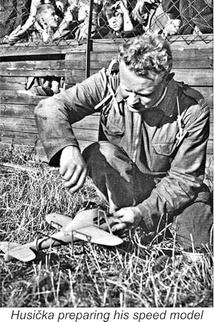
By the time the war ended, Husička had become aware of the diesel engines which had been developed during the wartime period in his native Czechoslovakia as well as in other countries such as Switzerland, Sweden, Italy, France and Germany. This led him to begin a collaboration with the legendary Josef Pfeffer, which resulted in the development of a number of new engine designs over the following 5 years or so. Notable among these designs was the Letmo MD-2.5 diesel, a 2.47 cc rear disc valve (RRV) development of the crankshaft front rotary valve (FRV) Husička 2.5 model. A prototype of By 1949, Husička had also become interested in the growing field of control-line speed, an activity which he approached with his usual dedication. From the outset his models were extremely aerodynamic, using drop-off dolly undercarriages. Following a somewhat shaky start when his first model refused to take off from the dolly, doing tether car impressions instead (!), Husička used his refined 1950 design to establish a new Czech control-line speed record for 2.5 cc models at 105.12 km/hr (65.32 mph). The engine was a tuned example of Husička's own Letmo MD-2.5 diesel design. At around this same time he also constructed some of the first glow-plugs in Czechoslovakia using some platinum-iridium wire which a colleague had somehow managed to obtain.These plugs had metric threads.
Another noteworthy control line model built by Husička in 1952 was a 10 cc design powered by a Nordec RG10 engine which Husička had somehow managed to obtain from England. This combination recorded a speed of 208.50 km/hr (129.56 mph) at a contest in Brno in September 1952. As far as I'm able to determine from the records currently at my disposal, this was one of the fastest speeds ever officially recorded by a Nordec in competition. The engine was most likely one of the very rare Nordec Special Series II models - surely no-one ever got the Mk. I Nordec to go that fast!?! Husička carried on into 1953, developing a further-improved version of the Letmo MD-2.5 diesel which had served him so well. However, later in that year a serious illness forced him to retire from the field of top-level model competition. Naturally, he Meanwhile, the Czechs had followed the lead of their idealogical colleagues in Russia by assigning responsibility for the further development of aeromodelling in Czechoslovakia to a new organization named SVAZARM. Established in late 1951, this was a para-military organization modelled very closely upon the Soviet Union's DOSAAF organization, which had been created in mid 1951 through the amalgamation of three formerly-separate organizations.
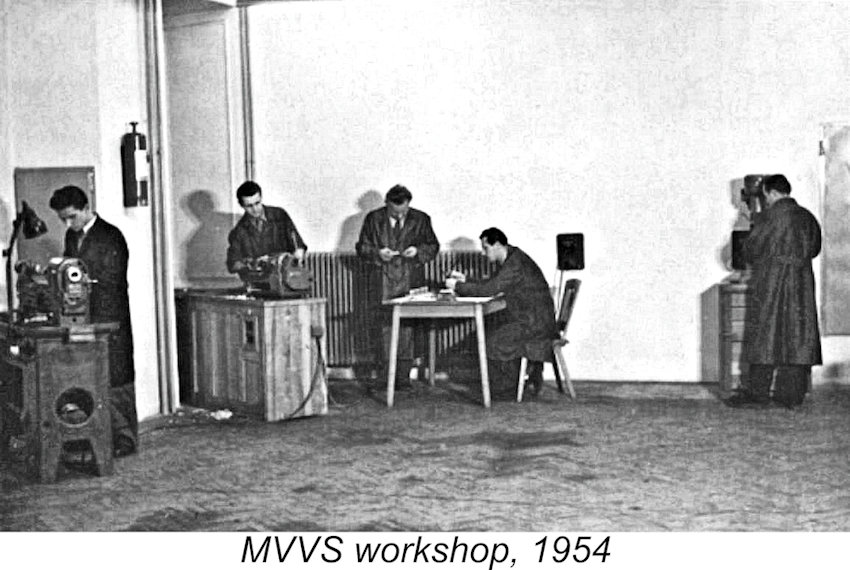
Following the less-than-satisfactory results achieved in a 1953 international contest between modellers from Czechoslovakia and Hungary (always a heated rivalry!), Husička became a bit of a squeaky wheel, vigorously drawing SVAZARM's attention to the lack of suitable engines for use by Czech modellers in such competitions, particularly (at that time) in the prestigious 5 cc and 10 cc classes. This open criticism from such a respected figure in the Czech modelling world led directly to the decision The Centre opened its doors on October 15th, 1953, with the primary goal of developing engines and model designs which would propel Czech modellers to the achievement of World Championship honours. From an early date, the Centre was largely staffed by recognized experts in the field of competition aeromodelling. In early 1954 Husička was joined by expert fellow competitors Luboš Kocí and Josef Sladký, thus creating the nucleus of a formidable in-house design and competition team. The Centre was very sparsely equipped at the outset, but this situation was progressively rectified as time went by.
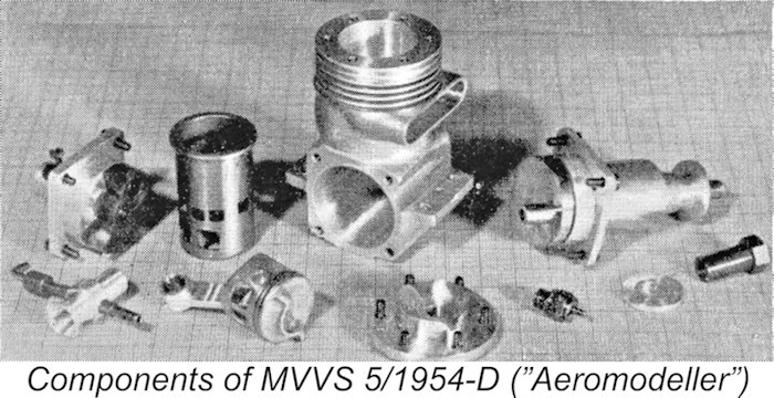
Using this engine, Mir Zatocil achieved the first honours for MVVS in international competition when he won the 5 cc class at the International Competition for People's Democratic States in 1954 Although the design of the MVVS 5/1954-D owed much to that of the Dooling, further development was evidently required to bring it fully up to the performance level of its American progenitor. Evidently recognizing this, the Czechs had not sent any representatives to the 1954 World Championship event held that year at The Hague in the Netherlands. Had they done so, Zatocil's speed set the same year in Moscow would have given him a still creditable 6th place tie with Pete Wright of Great Britain.
A further successful design from 1954 was the 1.5 cc MVVS 1.5/1954 model which was made in both diesel and glow-plug forms. Developed primarily for free flight use, this design was sufficiently impressive that the diesel version subsequently became the basis for the well-known START 1.8 cc model which entered commercial production in 1957. These initiatives have been comprehensively reviewed by Maris Dislers in a separate article to be found on this website. Zatocil's 1954 success in the 5 cc category was certainly praiseworthy given the standard of the prevailing Dooling, At the National control-line competition held at Prague in the Spring of 1955, Josef Sladký achieved a speed of 174.70 km/hr (108.56 mph) with the new MVVS model S-25 racing engine, thus establishing a new Czech record. A further improved model, designed and constructed by Sladký and Kocí, hence colloquially known as the SK-25 "Broucek" (Poppet) model, was in preparation for the upcoming 1955 World Championship. MVVS Takes On The World
Sladký's one-off 2.49 cc engine was in most respects a conventional racing motor of its time - lightweight ringed aluminum piston, twin ball-bearing shaft, oversized transfer passage, ultra-short stroke (16.0/12.4 mm), rear disc valve All of the Czech engines used suction fuel feed from a metal chicken-hopper tank which supplied fuel to an offset needle valve. Their most striking common visual feature was the expanding-section rearward-swept exhaust stack seen on all models. The MVVS 2.5/1955-D motors used by the other two team members in Paris differed considerably from Sladký's winning powerplant. Apart from utilizing FRV induction, they also featured more conventional bore/stroke measurements of 15/14 mm. Jaroslav Kocí subsequently rebuilt one of these engines in rear disc valve form and won with it at the 2nd annual International People's Democratic States contest in Vrchlabi, Czechoslovakia. He recorded a speed of 179.98 km/hr (111.84 mph) on the 11th of September 1955, subsequently achieving a significantly higher speed of 203.53 km/hr (126.47 mph) on thinner lines to establish a new 2.5 cc world record. This modified disc valve engine became the prototype for the following year's 2.5/1956-D model.
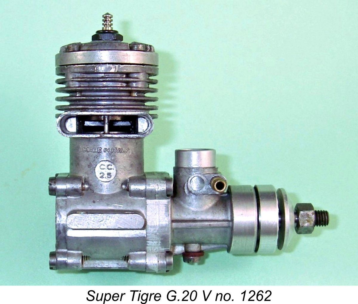
Sladký's 1955 World Championship win left the MVVS research centre facing the usual problem encountered by winners in any field of activity - having reached the top, how were they to stay there? The answer of course was by continuing to develop the remarkable 2.5 cc glow-plug engines that had served Sladký and Kocí so well. But the pressure was on - Super Tigre had become used to winning and would not take their 1955 defeat lying down. Already they were pointing the way toward the future with a lapped piston version of their G.20 S model, and further improvements were in the works which were soon to result in the introduction of the improved Super Tigre G.20 V design.
Looking towards the future and having regard to the remarkable performances achieved by Jaroslav Kocí with his modified MVVS 2.5/1955-D engine, the MVVS designers decided that the very precise timing, short gas pathway, rapid opening and closing and tuning flexibility of the rotary disc valve were the key to staying ahead of the opposition. The crankshaft front rotary valve (FRV) system that had served Super Tigre so well for some years with their G.20 design had shown promise for MVVS in 1955, but MVVS wanted the flexibility and short direct-entry gas passage that the disc rear rotary valve (RRV) arrangement provided. They had used this system all along in their 5 cc racing models, and were to continue to do so. Now the 2.5 cc models were to follow a similar pattern. Accordingly, during the winter of 1955-56 MVVS embarked upon a program of further development of their 2.5 cc racing glow-plug model using RRV induction as a major element of their evolving design strategy. Doubtless Kocí's very successful rear-disc modification of the MVVS 2.5/1955-D served as the basis for these developments. The resulting prototypes showed considerable promise and the design that was individually produced in minimal numbers for the exclusive use of selected Czech experts, the MVVS 2.5/1956–D, proved to be a formidable competition powerplant.
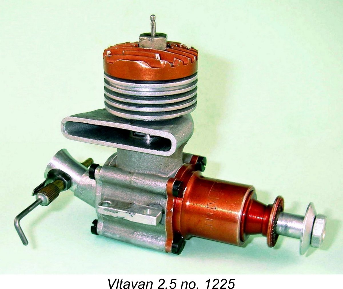
A real rarity which appeared at this meeting was a one-off MVVS prototype disc-valve glow-plug motor known as the S-25R. This design employed a fascinating concept - differential displacement! It featured a ringed alloy piston having a diameter at the power-head end of 16 mm, which combined with the 12.4 mm stroke to give an upper cylinder displacement of 2.49 cc. However, the piston featured a step at the bottom of the skirt which gave the piston a diameter of 18 mm as seen from the crankcase. The lower cylinder was of course stepped to match. The result was a crankcase displacement of 3.16 cc. The intent was clearly to enhance the motor's pumping capacity and thus promote the ability to induct and transfer more fuel mixture – in effect, a form of supercharging. The S-25R was reportedly more powerful than the conventional versions, but was not used in the actual event in Florence due to designer Sladký's concern that the bore measurement at the bottom of the cylinder might possibly give rise to disqualification. Possibly true, but still ........ neat idea! The MVVS engines used by Sladký and his compatriots were individually built in very small numbers to the highest standards. It would clearly have been impossible to produce equivalent engines commercially at anything like a reasonable price, and no attempt was made at this time to do so at the MVVS workshops. Accordingly, in 1957 a "consumer" version of the MVVS 2.5/1956-D was put into series production at an entirely separate production facility under the name of Vltavan. Known as the Prague-Modrany factory, this facility was located in Prague, very distant from the MVVS workshops in Brno. A 5 cc model based upon the earlier MVVS 5/1954-D was also produced. The Vltavan engines were named for the Vltava River which flows through Prague. I’ve discussed the Vltavan 2.5 and Vltavan 5 models in detail elsewhere. Although their handling and running qualities were generally very good, the Vltavan versions of the MVVS racing models unfortunately lacked the precision of their MVVS prototypes, hence failing to approach MVVS standards of performance. They did however represent a source of engines of reasonable if not world-beating performance with which aspiring competition flyers could gain vital experience. As such, it's probable that they went a long way towards achieving their intended purpose. A New Direction: MVVS Develops Their First Stunt Motor
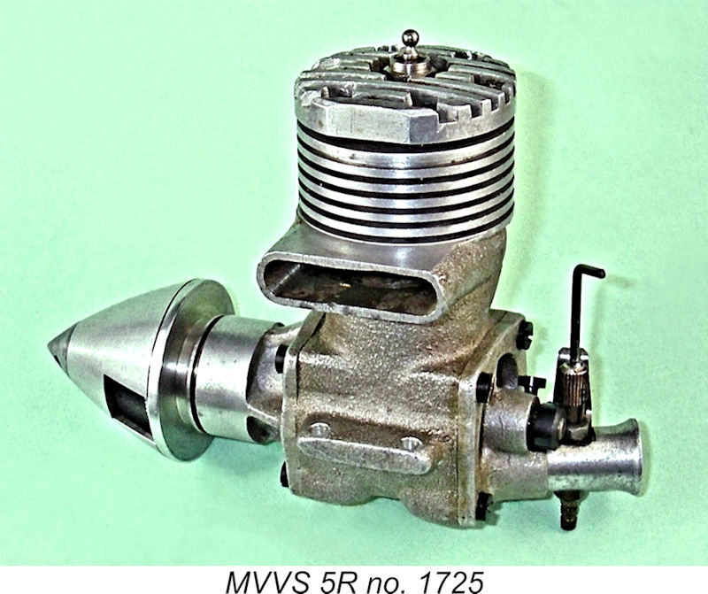
More to the point in the context of the present article, MVVS further expanded their competition horizons in 1957 by developing an updated version of their successful 5 cc MVVS 5/1954-D glow-plug design mentioned earlier. The revised design retained the Dooling-influenced Bore and stroke of this variant were 20 mm x 15.7 mm respectively. The engine featured the same unique intake orientation adopted on the companion MVVS 2.5R model which was in development concurrently (see below). Like all previous MVVS designs, the 5R-57 was individually built in very small numbers for the use of recognized Czech experts. One such example was used by MVVS employee Bohumil Studený to break the world Class II speed record at 243.96 km/hr (151.6 mph) in September 1957. Not bad going on two lines! It's worth noting in passing that in 1964 this design was put into limited series production with minimal changes under the designation MVVS 5R. It was initially produced in a 50-piece series at the specific request of SVAZARM's model power boat racing Many illustrations of the MVVS 5R show it with its exhaust stack oriented to the right, but published drawings from the contemporary Czech modelling media indicate that the engines were actually supplied with their stacks on the left-hand side, as seen on both the 5R-57 and the 5R illustrated here. I’ll discuss the rationale for this orientation in a later section of this article. Although perfectly suited to model aircraft use, for which the illustrated example is clearly set up, the 5R was undeniably on the brink of becoming a bit outdated by the all-out speed engine standards then being established by Super Tigre and K&B among others. As a result, it seems to have found its greatest favour in the field of tethered hydroplane racing, in which it reportedly enjoyed considerable contest success over a period of over five years, establishing a number of records in the process. The 5R's success culminated in 1969 with J. Šustr's establishment of a new European record of 157 km/hr in the Class A2 category for water-screw hydroplanes.
The 20 mm bore was unchanged, but the stroke of the stunt model was increased by 2.3 mm to 18.0 mm, both to provide the additional displacement and generate improved torque at moderate revs. In addition, the disc valve and cylinder port timing were tailored to the speeds expected for a stunt engine, where torque at moderate revs was far more important than sheer top-end power. The engine used a revised backplate incorporating a downdraft carburettor, the idea being to keep the engine nice and compact and have the intake readily accessible for hand starting.
It's my personal opinion that there were good reasons for the factory adopting this exhaust orientation, a point which I'll discuss in detail when we get to the MVVS 2.5R-58 in a subsequent section of this article. That said, several illustrations in the well-known books “Modelárské Motory” by Jirí Kalina and “Czech Model Engines” by Jirí Linka and Jan Kafka show examples of this engine with the stack on the right. It's entirely possible that these engines may have been switched around by their owners.
Indeed, the 5.6A continued to place internationally at the very highest levels deep into the 1970's. The engine was still sufficiently competitive as late as 1976 to power the Czech team to third place overall in that year's control-line stunt World Championships. The success of the engine over such a long period of time actually forced MVVS to resume limited production for a time beginning in 1970, offering both control-line and R/C models.
Perhaps the most impressive aspect of the outstanding record compiled by the 5.6A was the fact that these successes were achieved in a competition category for which its prototype, the 5R-57 racing engine, had never been envisioned! A fine example of taking what you had and adapting it to meet an entirely different set of requirements.
The intention of the designers was apparently to offer a lower-cost and lighter-weight stunt engine which would meet the needs of a broader spectrum of the modelling public. However, tests showed that it was significantly less powerful than the 5.6A model - the manufacturers claimed only 0.54 BHP @ 13,800 rpm as opposed to their cited figures of 0.63 BHP @ 15,100 rpm for the 5.6A. Accordingly, serious Czech stunt fliers like Gabris continued to use the latter design for international events. The 5.6AL appears to have remained a "consumer" engine throughout its production life. It was evidently never offered in an R/C version. The MVVS 5.6A On Test
Whoever he was, the tester reported most favorably on the engine both in terms of its construction and its performance. Bore and stroke were correctly reported as 20.0 mm x 18.0 mm respectively for a displacement of 5.66 cc (0.345 cuin.). This compares with the dimensions of the parent 5R-57 speed engine, which used a bore and stroke of 20 mm x 15.7 mm for a displacement of 4.98 cc (0.304 cuin.). Weight of the 5.6A was reported as being 7.25 ounces, which is very close to the factory's claimed weight of 210 gm. My example weighs almost exactly the latter figure. The claimed output of 0.63 BHP @ 15,100 RPM for the 5.6A does not appear to be an unreasonable claim by any means when one looks at the rather advanced specification of the engine. However, the example tested by “American Modeller” could not match these figures, their published findings being 0.54 BHP @ 13,200 rpm on a 3% nitro fuel - pretty much the same as the MVVS factory claim for the alternative 5.6AL. No doubt the individually-prepared"works" engines from 1957-58 may well Still, the cited performance was very good indeed for a .35 cuin. stunt engine, while the starting and running qualities of the motor were reportedly beyond reproach. My own example confirms these impressions completely - it is extremely easy to start and runs superbly with excellent needle response. I've never flown mine, but I have no doubt at all that it would be a very fine performer in a model. While they were busy developing what came to be an all-time stunt classic, MVVS had of course remained very active in the control line speed category in which they had first made their name. Let's return to 1957 to take up that story once more. Turning Up the Heat: The MVVS 2.5R-58
In the face of the ever-mounting opposition, the MVVS design team went back to the drawing board and decided to try the effect of reverting to the "bulge bypass" form of transfer system which had been pioneered in the USA by Dooling and had been used for some time in the 5 cc MVVS designs. This configuration had the dual advantages of minimizing both crankcase volume and piston weigh as well as improving piston cooling. The carburettor assembly of the 2.5/1956-D had evidently proved entirely satisfactory, so all that was seen as being necessary was a change in the main crankcase/cylinder/piston setup. The resulting design was something of a cobbled-up affair - it retained the backplate of the 2.5/1956-D (albeit in a different orientation) and also in effect used the same front end, but featured a revised crankcase casting which incorporated the bulge bypass. The piston and cylinder liner were of course amended to suit the revised transfer system. In most respects the new model was simply a scaled-down version of the record-setting 5 cc MVVS 5R-57 mentioned earlier.
Only ten examples of the new design had been produced in the MVVS workshops for the 1957 championships. As chief designer for the Centre, Josef Sladký presumably had the pick of the batch. The factory claimed that tests on Sladký's actual winning engine had shown flash figures as high as 0.61 BHP @ 22,000 rpm on a fuel containing 40% nitromethane and 20% nitrobenzene. Scary - nitrobenzene is a powerful carcinogen. If true, this was almost certainly the highest specific output ever obtained up to that point from a model engine. Frankly, one has to wonder whether a degree of psychological pressure was being exerted here ............ that having been said, testing of my own example has confirmed that this engine was a truly outstanding performer by the standards of the day.
Like MVVS, the MOKI Institute owed its establishment in large part to the efforts of a single individual, in this case the expert flier and experienced engine designer Gyula Krizsma, who had been associated with the Alag engines among others and had achieved the previously-mentioned fourth-place finish in the 1957 World Control-Line Speed Championships shortly after the establishment of MOKI. The goal of the new Centre was the development and construction of engines for use in model aircraft as well as for military purposes. One of the first priorities was the development of a racing 2.5 cc glow-plug motor which would beat the all-conquering MVVS and Super Tigre opposition.
In addition, things were beginning to stir in America, where Bill Wisniewski was already at work at K&B in California developing the special 2.5 cc engines that were to take him to the highest levels of World Championship speed competition by 1960 and were to lead to the release of K&B's famous Series 61 and Series 64 models. Despite these clear indications of more intense competition to come, the total dominance which the revised MVVS design had exercised in 1957 seems to have convinced MVVS that their 1957 winner would require relatively little modification to remain on top in 1958. Consequently, they contented themselves with making only a few relatively minor experience-based tweaks to the 1957 championship-winning prototypes to produce their classic 2.5R-58 model. They were almost right - but not quite!! The MVVS 2.5R-58 - Design Considerations The MVVS 2.5R-58 was basically a conventional racing engine of its day, featuring the classic combination of detachable front and rear covers, twin ball-bearing shaft, ringed aluminum piston, rear rotary disc valve, offset plug, etc. All cast components were produced by sandcasting - scarcely surprising in view of the very limited production envisioned at this time. Bore and stroke of the 2.5R-58 were the standard Continental 15 mm x 14 mm respectively for a displacement of 2.47 cc. The engine weighed in at 5.1 ounces. Claimed output for the team engines was 0.44 BHP at 19,000 rpm - rather lower than the cited figures for Sladký's 1957 winner, but still very impressive indeed by the standards of the day. My own tested example produced very comparable figures.
The intake venturi on these engines is located at the bottom of the backplate rather than in the more conventional upper right position (viewed from the rear). Furthermore, it is angled to the right in such a manner that it protrudes slightly beyond the outline of the main casting. Hence, mounting the engine in a speed pan would require that either the pan or the venturi (or both) be trimmed to allow the engine to be mounted within the pan and still maintain adequate air flow to the intake.
To accomplish this, they simply took the backplate from the earlier 1956 model and rotated it through 90 degrees. All that was then required was to position the drive pick-up in the disc valve at 90 degrees from its former location in order to re-establish the correct timing. One can clearly see in the attached rear view how the outline of the backplate mounting flange where it joins the main case (behind the needle valve) is intended to conform to a normal case when it is rotated through a 90 degree angle. Presumably this use of an existing component was undertaken for reasons of economy - it side-stepped the need to make a new backplate pattern and indeed allowed the use of already-existing components taken from earlier and now obsolete models. It also maintained a tangential component of the velocity of the gas entering the crankcase though the venturi, which may also have been a consideration as we shall soon see. In his November 1960 test of the MVVS 2.5R-58 (see below), Peter Chinn noted this anomaly but failed to consider the possible reasons for this seemingly awkward arrangement. However, reasons there must surely have been - the arrangement had been pioneered on the 1957 2.5 cc and 5 cc "works specials" and unquestionably would not have been transferred to the 1958 2.5 cc model without good cause. So it's worth trying to understand the designers' thinking in this context. Let's have a go ... In order to understand what was going on here, it's necessary to consider the chicken-and-egg syndrome and try to sequentially identify the design considerations which appear to have influenced the designers' thinking. I've given this a lot of thought and have come to the conclusion that this unusual backplate arrangement had its origins in the decision to adopt the Dooling bulge-bypass system which had been in use on the larger MVVS racing glow engines since 1954. Let's try to trace the domino effect which stemmed from this decision. The Dooling transfer system employs a hemispherical cavity on the transfer side which serves at the bypass passage. With the piston in place, this cavity has no direct communication with the lower crankcase, thus possessing the advantage of minimizing crankcase volume and thus improving the engine's base compression and pumping efficiency. However, the absence of direct communication with the lower crankcase means that an alternative pathway has to be provided for fuel mixture to enter the bypass cavity.
Now with the exhaust stack located on the right in the conventional manner, the side-load during the power stroke would all be directed to the transfer side of the piston. But this side of the piston was extremely poorly equipped to deal with these loads - there simply wasn't much of it left! Not a good situation either for mechanical reliability or engine longevity. However, there was an obvious fix - switch things around so that the exhaust stack was on the left (viewed from the rear). If this were done, the power stroke side-thrust would be resisted by the unbroken side of the piston skirt. The almost non-existent transfer side would only have to deal with the far lesser loads involved in the compression stroke. Hence there were compelling mechanical arguments in favour of a left-side location of the exhaust stack. But what about the possible effect upon transfer efficiency? If such a relocation of the exhaust stack would have compromised engine performance in any way, there's no possibility that the MVVS designers would have adopted it - they would have accepted that the price to be paid for improved mechanical integrity was simply too high in performance terms. In a World Championship speed context, ultimate performance was the imperative rather than longevity. It's thus clear that the performance implications of making this change must surely have been well considered by the MVVS design team. Here another consideration entered the picture - that of crankcase swirl. The gas in the crankcase of a two-stroke engine does not sit still - it swirls quite strongly in the direction of rotation of the shaft. At the speeds at which racing glow-plug engines were even then operating, this swirl effect was quite considerable. Speed engine designers were beginning to appreciate the potential benefits of this and were planning their engines to maximize the positive effect of crankcase swirl on the transfer process. The swirl imparted considerable velocity and hence kinetic energy to the mixture in the case, and this energy could be harnessed to help move the gas into the bypass passages more rapidly if those passages were appropriately placed and designed. In effect, the crankcase was being seen as a kind of centrifugal pump which could assist in the transfer process (remember, this was before the advent of tuned pipes!).
Hence the conventional orientation of the cylinder works fine with the typical vertical bypass passage opening tangentially directly off the crankcase in the normal manner for loop-scavenged motors. But in the case of a Dooling set-up, the mixture enters the bypass more horizontally than vertically, crossing just below the piston crown in order to do so (and thereby contributing very significantly to the cooling of the piston crown). If you think about the swirl effect for a second, it becomes intuitively apparent that a bulge bypass transfer system is best located on the right of the engine! The swirl effect will then throw the gas straight into the bulge where it is wanted.
But what about the implications for the incoming charge of mixture which was to be transferred during the next cycle? Well, if one thinks about the fact that we want the cool fresh gas to enter the case, be picked up by the crank-induced swirl, cool the piston and arrive at the entry to the bypass at just the right time, we may gain some insight into the reasons why MVVS located the intake where they did. If you mentally follow the swirl with the Dooling-type transfer set-up on the right (viewed from the rear) and the intake located at the base of the backplate, you'll see that the cool fresh charge entering the case during the induction phase will swirl with the crank, cool the piston and arrive at the piston ports at just the right time to head in the desired direction with considerable kinetic energy. This might be expected to minimize the residence time in the crankcase of a given incoming charge of mixture - good for internal cooling. Not only that, but the rather odd orientation of the intake itself (angled to the right) would impart a tangential component to the velocity of the incoming gas charge in the direction of swirl, thus minimizing any disruption of the swirl effect as the fresh charge entered the case. Finally, the induction port would be completely unobstructed by the con-rod big end during the entire induction phase. Job done ...…………
The similarly-designed bulge bypass MOKI S-1 from Hungary which took the first two places in the 1958 championship was identically oriented, clearly implying that the engineers at MOKI agreed with the above assessment. The examples of the MVVS encountered today with stacks on the right (and occasionally with the backplates incorrectly positioned) are almost certainly the result of interference on the part of owners who are unaware of the designer's intentions. It's worth noting in passing that when I was researching my earlier article on the Dooling 61, I encountered several discussion threads in which a number of old-timers stated categorically that most serious users of the Dooling 61 switched their exhaust stacks to the left purely on account of the resulting improvement in performance. A couple of individuals claimed that the Dooling Brothers were well aware of this, to the point that they would supply new engines in that configuration upon request. One individual actually recalled a long-ago conversation with Tom Dooling in which Tom explained the improved performance resulting from this stack orientation. I was fascinated to read that Tom's explanation was almost identical to that summarized above which I had previously developed independently as a result of my long direct acquaintance with such engines. I may be wrong, of course, but that's how I see it at present. If anyone out there has a better explanation for the odd placement of the intake on this engine, let's hear it! I maintain that there must have been a compelling reason for the engine being set up as it was. The above explanation makes sense to me at least ............
Of course, if the Czechs had been able to repeat their 1957 performances, they would have been right in there for a chance at the overall win. Viewed in that light, their decision to stand pat with what amounted to the same engine that they had used in 1957 might be seen as justified - they could not have foreseen that their team members would fail to extract comparable performances to those achieved in 1957 from what was presumably a further-refined design. As it was, the Czech team had to content themselves with third, fourth and fifth individual places and second place in the team standings behind the Hungarians. The Italians used their now-traditional Super Tigre G.20S and V engines with lapped pistons, but for the first time employed a pressure fuel tank in which the pressure was supplied from the engine crankcase. Despite this, they could not match the performances put up by the Iron Curtain specials. A Change in Policy
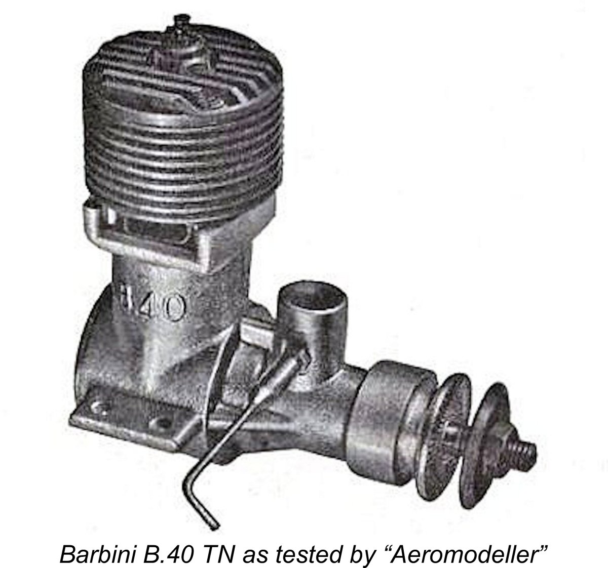
The only record that I can find of a Vltavan appearing in international competition was an official flight by Britain's Pete Wright at the 1957 championship meeting. Wright switched to a Vltavan 2.5 (probably obtained at the meeting given the fact that production had only just commenced) after his Barbini B.40 TN expired, but his speed of just over 100 mph was no threat to Sladky's winning 134.2 mph figure. Accordingly, it was becoming increasingly apparent that the strategy of putting large numbers of second-rate MVVS clones into the hands of ordinary modellers was perhaps not the most productive course of action in terms of improving the capabilities of Czech contest modellers. If a way could be found to increase the availability of genuine MVVS engines, the fliers who had been struggling to overcome the shortcomings of the Vltavan models would have far better equipment with a greatly reduced frustration factor, thus facing fewer barriers to the achievement of higher standards of performance. In addition, the plain fact was that as matters stood, the MVVS operation represented an ongoing drain upon State resources. As long as it was limited to the development and manufacture of minimal numbers of racing "specials" for the exclusive use of a mere handful of top-ranked modellers, the operation generated no revenue to offset its considerable costs. This state of affairs was clearly unsustainable.
The first engine to be produced in this way was the MVVS 25-D, a plain-bearing development of the 2.5D-58 ball-bearing diesel. The use of a plain bearing was reportedly due to the very limited availability of high-quality ball bearings in Czechoslovakia at the time. Those that were available were reserved for the racing glow-pug models. This engine was very well received, and deservedly so - it was a good ‘un! In his test of the 25-D published in the November 1958 issue of “Model Aircraft”, Peter Chinn characterized it as "the most powerful plain bearing 2.5 cc diesel I have the illustrated well-used example which I still flew occasionally until very recently, over 60 years after it was made, and boy does it go! Latter-day testing of this example has shown that if anything it slightly exceeds the output reported by Chinn, albeit at a somewhat lower speed. I found an output of around 0.310 BHP @ 14,000 RPM. This is a remarkable performance for a plain-bearing 2.5 cc diesel of 1958 vintage. In the following year of 1959 the 25-D was joined in limited production by the 2.5R-58 and 5.6A glow-plug models. The original 2.5R-58 was of course an individually-built "experts-only" model designated for the exclusive use of a few top Czech speed flyers. When the decision was taken to put the 2.5R-58 into series production, the original 1958 design was carried over more or less wholesale, although there must surely have been a realization that assembly tolerances would necessarily be somewhat compromised by the constraints imposed by the production line, which would dictate that each engine would receive considerably less individual attention.
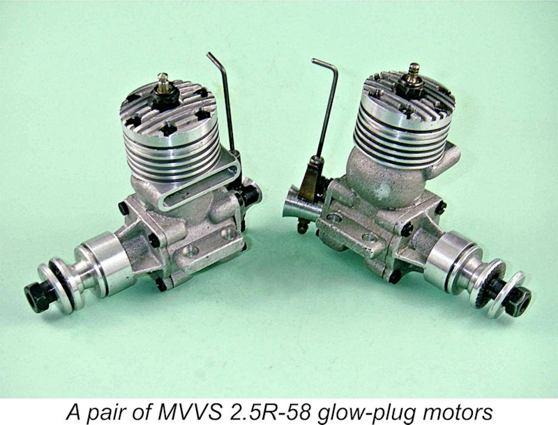
The 2.5R-58 was produced in relatively limited numbers, albeit vastly higher than those of previous years. The production versions were all given serial numbers which were stamped into the underside of the left-hand mounting lug (looking forward in the direction of flight). According to Kalina, some 2000 of them were made in total over a three-year period. My own pair bear the serial numbers 833 and 1865, seemingly consistent with Kalina's estimate. My own testing of these examples has more than confirmed the manufacturer’s performance claims. Use of the engine was by no means confined to model aircraft - Kalina tells us that the 2.5R-58 also put up a number of record performances in both airscrew and waterscrew-driven tethered hydroplanes as well as being used successfully in model cars. From the standpoint of the present-day collector, one consequence of the 2.5R-58's relatively low production figures coupled with its outstanding performance was that very few of those who managed to acquire one did so merely to look at it - most of them got used for their intended competition purposes. Moreover, those that did see competition use (the majority) tended to suffer the usual fate of competition engines by being modified in various ways to better tailor them to their intended applications. As a result, un-flown examples of the engine in original unmodified form are very rare today. The MVVS 2.5R-58 Competition Record We already noted the outstanding results achieved in 1957 with the original prototypes of the MVVS 2.5R-58. We also saw that while the engine carried similar levels of performance into 1958, this proved insufficient to stem the MOKI tide in that year. Let's see how the engine fared in subsequent international events. 1959 was very much a development year at MVVS as the Centre strove to become established on a sound commercial footing not only by engaging in limited series production of the 2.5R-58, the 5.6A and the 25-D but also by developing several new models which were intended from the outset as production models rather than experts-only specials. The latter included the previously-discussed lapped-piston MVVS 5.6AL (which eventually appeared in 1960); the prototype of a new 1 cc diesel (which finally entered series production in 1962); and a forerunner of the giant motors now so familiar to latter-day R/C flyers in the shape of the 26 cc MVVS 26-59, of which only some 16 examples ended up being manufactured. It appears that the change in focus and the effort involved in switching the MVVS centre over from a research centre to a series producer of model engines limited the availability of staff time for the further development of the 2.5R series. The engine was not entirely neglected, receiving a few minor tweaks (including a needle-roller big-end bearing) to create an individually-constructed variant known as the 2.5R-59. The claimed output of this model was increased to 0.47 BHP @ 19,500 rpm - a truly stellar performance by 1959 standards.
Most of the Czech team members were MVVS employees, and it appears that it was not found possible to free up enough staff time to allow participation in the 1959 World C/L Championships at Brussels, Belgium. In addition, MVVS boss Zdeněk Husička had apparently suffered a heart attack from which he was still recovering. Accordingly, the 2.5R-59 did not see contest action outside Czechoslovakia in 1959. However, this was certainly not true of the production version of the 2.5R-58! The majority of these engines remained initially within the Iron Curtain countries, but a few examples found their way to the West and were put to good use there. At the 1959 World C/L Championship meeting at Brussels, K. Jaaskelainen of Finland managed a very creditable 193.92 km/hr (120.5 mph) for 6th place using one of the early production versions of the 2.5R-58 which he had somehow acquired. A highly creditable performance for a single individual working without official support! By 1960, when the World Championships were held at MOKI's home base at Budaörs airport near Budapest, things at the MVVS Centre had stabilized to the point where a return to the fray was possible. Moreover, there must have been a considerable incentive within the Czech team to demonstrate that they were still well able to give MOKI a run for their money in MOKI's own back yard! The 2.5R-59 was ready and waiting for its chance to show what it could do. Apart from that, by 1960 considerably more examples of the production MVVS 2.5R-58 had now found their way into the hands of modellers outside Czechoslovakia. While the 2.5R-59 was used by the Czech team at the 1960 Championships, the "production" version of the 2.5R-58 appeared in the hands of entrants from several other countries including the returning K. Jaaskelainen of Finland (121.2 mph), the USSR entries of Michal Vasilchenko (125.5 mph) and V. Natalenko (126.8 mph) and the German entrant G. Zeigler (108.7 mph). MVVS was thus very well represented internationally!
Despite this, the performances achieved at this meeting by the official Czech team were most impressive and were in fact the best ever achieved using an MVVS 2.5R engine. Admittedly, this was significantly helped by the fact that the Czechs followed the lead of the Americans by using mono-line control for the first time. Zbynek Pech's third-place speed of 141.1 mph at the 1960 meeting was the fastest speed ever recorded by a 2.5R in a sanctioned FAI event, handily beating the best MOKI speed of 133.6 mph at the same meeting (using two lines). Indeed, had it not been for the fact that the 146.6 mph two-line winning speed of Italy's Ugo Rossi To further rub it in as far as MOKI was concerned, after the conclusion of the contest Pech established a new world record of 244.61 km/hr (152 mph) for the 2.5 cc class using 0.011 in. mono-line, which was thinner than permitted for the actual championship event. This was the all-time fastest speed ever recorded by the MVVS 2.5R-59, and a highly creditable one at that. Such a performance clearly implies that the peak power output claims for the "works" engines were little if at all exaggerated.
Of course, Iron Curtain products were not viewed positively in America during this period given the state of Cold War tension between the USA and the Iron Curtain bloc. Despite this, one American modeller who did fly one of these engines was Lt. David Cotton, who used a 2.5R-58 in 1961 for speed flying in the United States, reaching speeds of 191.5 km/hr (119 mph) under the new FAI rules (no nitro) and as much as 220.1 km/hr (138 mph) on nitro. These were the highest speeds ever achieved with one of these engines outside the official Czech team. Lt. Cotton's engine finally expired when it threw a rod after Cotton had used it to qualify to fly in the 1961 US team eliminators. Probably just as well - the spectacle of an American competitor using an Iron Curtain engine in an international competition might not have been viewed favorably in certain circles at the time, particularly given Lt. Cotton's military connections .............. The MVVS 2.5R-58 On Test One of the above-mentioned escapee examples of the MVVS 2.5R-58 ended up being loaned to resident “Model Aircraft” engine tester and commentator Peter Chinn, who included the engine in his excellent series of tests published in that magazine. Chinn's test report appeared in the November 1960 issue. For reasons which are unclear at this late juncture, Chinn called the engine the MVVS 2.5/1959. All I can say is that I have never seen a Czech reference to this model under any name other than the MVVS 2.5R-58. Accordingly, I will continue to use this name for the engine. The 2.5R-59 was a tweaked version (as described above) having a needle roller big-end bearing which was never put into series production. Chinn's test engine did not feature such a bearing.
The case of Chinn's test example must have been switched over by the engine's owner, who had clearly failed to consider the possible reasons for the as-supplied configuration. Neither did Chinn, who may have been unaware of the original stack orientation. In his November 1960 test, Chinn did note the apparent anomaly of the intake location but failed to consider the possible reasons for this rather awkward arrangement.
Chinn commented on the excellent compression seal provided by the two piston rings, and I can confirm that - my two run-in but un-flown examples feel far more like lapped engines than ring-equipped models! Another feature that drew favorable comment was the design of the rotor disc. Most unusually, this was made of cast iron on this engine - a very durable and suitable material, albeit rather heavy. The disc was very carefully balanced, utilizing the same excellent disc mounting system as used on previous MVVS engines and their Vltavan derivatives. The result was a rotary valve that was second to none in the context of its times. Chinn was extremely impressed with this engine, characterizing it as "a remarkable 2.47 cc glow-plug motor". I've bench-run both of my own examples of the engine and can confirm that they are remarkably easy to start and run both smoothly and powerfully. They are well up on my Vltavan 2.5's for revs. Quality of construction is superb, especially where it counts. I'm thus able to endorse Chinn's impressions completely. A full bench test of one of my engines found an even higher output of 0.470 BHP @ 18,500 rpm using a fuel containing 30% nitro. This is right up there with the claimed performance of the works-tuned Czech team engines. My own test of the MVVS 2.5R/58 may be found elsewhere on this website. A Russian Clone: the MD 2.5 Moscow Naturally, the 1959 introduction of the MVVS 2.5R-58 as a small-scale production model spelled the end of the Vltavan engines - by 1960, production of those engines seems to have ceased. The Czechs had realized that with racing engines it was more important to maintain standards of quality than it was to aim for mere quantity. But the Russians had yet to learn this lesson, and this was to lead to a repeat of the Vltavan situation with the MVVS 2.5R-58.
To that end, beginning in 1957 they arranged for the series production of what amounted to replicas of several established competition engines originating from outside the USSR. The Moscow facility at which these "consumer-grade" engines were produced was primarily involved with defence production. The production of model engines was added to the previously-existing workload of this facility as a sideline, the goal being to provide a range of competition engines for the use of Russian modellers in developing the skills required to compete at the international level. Early products of this operation included copies of the Webra Mach I diesel and Super Tigre G.21/29 glow models. The Super Tigre clone was designated the MD-5 Kometa, a quite successful effort which was destined to remain in production for several decades. My own tests have shown quite conclusively that a well-prepared example of the Kometa came surprisingly close to matching the performance of the Super Tigre original. A spot check of a correctly-configured example of the Kometa using an APC 8x4 prop on 30% nitro revealed an output of 0.694 BHP @ 18,000 RPM.
There were reportedly plans to produce some 10,000 examples of the Moscow over a 5-year period, but it seems highly unlikely that this figure was achieved. The motor was to all intents and purposes a copy of the MVVS original, but like the Vltavans before it the MD-2.5 lacked the precision necessary to realize or even approach the full potential of the excellent design upon which it was based. As noted above, the rather complex MVVS design was more than usually dependent upon extremely precise construction to deliver its full potential, and the MD-2.5 model never came close to achieving this production standard, falling even further short than its Vltavan predecessor.
The makers claimed an output of 0.30 BHP for this engine. However, a 1962 test of an off-the-shelf example obtained by the staff of “American Modeller” magazine found only 0.24 BHP on 30% nitro - not too impressive by comparison with the MVVS original! Poor compression seal was cited as a major contributing factor. Further details of the MD-2.5 appeared in the previously-mentioned article entitled “Iron Curtain Engines - Da? Nyet?” which appeared in the August 1962 issue of “American Modeller”.
It appears that the MD-2.5 did not remain in production for the planned 5-year period, being supplanted by superior Russian-made Super Tigre G.20 "Meteor" clones fairly quickly following its introduction. In addition to the Super Tigre G.20 copies, the Russians continued to turn out a number of other clones, including the aforementioned MD-5 Kometa, the MK-12V copy of the Webra Mach I and the Kharkov MK-2.5 copy of the MVVS 25-D. As stated earlier, the Kometa was a perfectly useable engine which remained in production for many years right up to the final collapse of the USSR in 1989 and perhaps beyond. My own tests have shown that the Kharkov MK-2.5 performed at a standard which at least matched that of the MVVS 25-D original. Conclusion As noted previously, the MVVS 5.6A remained highly competitive in international stunt competition right through to the mid-1970's, only giving way to more up-to-date designs as the ‘70's drew to a close. However, the situation with respect to the control-line speed arena was far less static - standards of all-out This forced the MVVS Centre to take a completely fresh look at the design approach to their high-performance 2.5 cc glow-plug engines. In fact, they had begun to experiment with a new rear-exhaust 2.5 cc model as early as 1960. The results of their thinking began to appear in late 1963 in the form of the first prototypes of the rear-exhaust MVVS 2.5RL motors. An era thus ended and a new one began. Still, the 1957 "bulge-bypass" MVVS 2.5R engines had by no means disgraced themselves! Remaining competitive at the highest levels against all comers for 5 years with minimal design changes was no mean feat and one which underscored the excellence of the original design. And of course, the 5.6A soldiered on ................ The final engines to be produced in the classic MVVS glow-plug motor series were the previously-mentioned MVVS 5R of 1964 and its companion 10 cc model of almost identical design called the MVVS 10R. This latter unit was produced in two distinct versions, the second and last of these appearing in 1965. This gave it the distinction of being the last MVVS "bulge bypass" model of them all. So there we leave MVVS at the dawn of a new era in model engine design. I hope that you've enjoyed this look at their first decade. Long may they continue! ________________________________ Article © Adrian C. Duncan, Coquitlam, British Columbia, Canada First published on MEN November 2011 This revised edition published here October 2024 |
 This article is an updated re-publication of an
 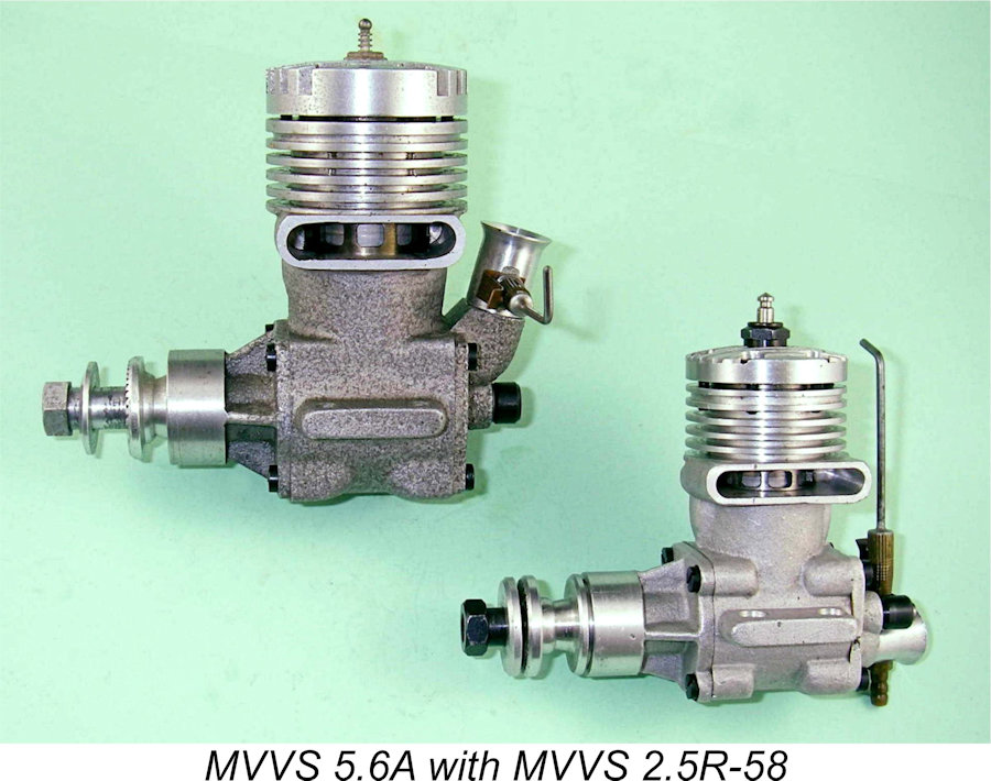 Naturally, the fact that no revenue was generated from engine sales during this period meant that these activities were undertaken entirely at State expense. This situation could not continue forever, and in 1958 the decision was taken to begin the process of making the MVVS enterprise self-sustaining by entering the field of commercial model engine manufacture.
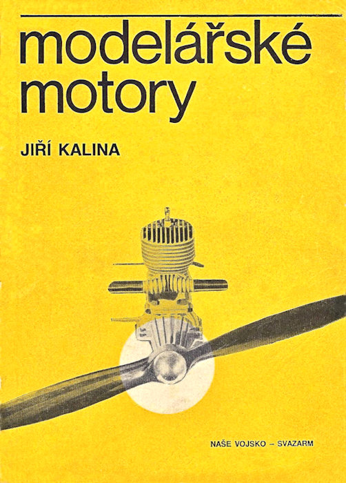 Before proceeding, however, it's necessary to pay tribute to the work of Ji
 relating to MVVS. I've drawn heavily upon this in writing the following text, and I freely admit that I'm very much following in Kalina's footsteps in presenting the following information, much of which is appearing for the first time in the English language. Thanks, Ji
 The MVVS story begins in 1953, when the Czechoslovakian state authorities decided that there was international prestige and political capital to be gained through the achievement of Communist success in the field of model airplane competition at the World Championship level. At first sight, it may seem a little odd that aeromodelling would be seen as a worthwhile activity into which to pour State resources. In fact, an important element of the Communist agenda at this time was to get their message of technological superiority out not merely to the leadership of the Western bloc but perhaps more importantly to the ordinary citizens of the countries in question. As an activity which was widely practised at the time by members of a broad spectrum of Western society (far more widely than it is today), aeromodelling provided a perfect stage on which to demonstrate the technical capabilities of the Communist states to the Western population at large.
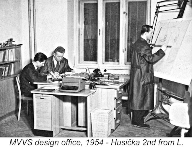
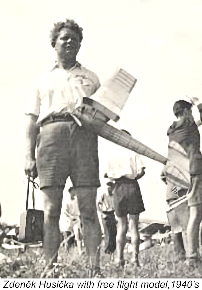 Husička was an experienced and very capable free-fight competitor who had become interested in model engines prior to the onset of WW2. His first design was the Letná 6.3 spark ignition engine which was later produced in small numbers during the wartime years by Gustav Bušek in Prague. In 1939 he constructed three examples of the Husička 22.5 cc sparker, which was a very advanced design for its time.
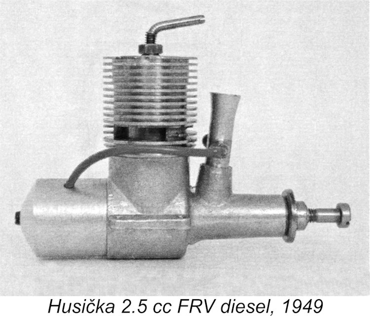 the original Letmo MD-2.5 was used by Husička in 1949 to finish third in the Czechoslovakian free-flight championships with an innovative model design featuring a revolutionary tail configuration and a folding two-blade propeller. He went on to win both the 1950 and 1951 Czech free flight championships with further developments of this model and motor.
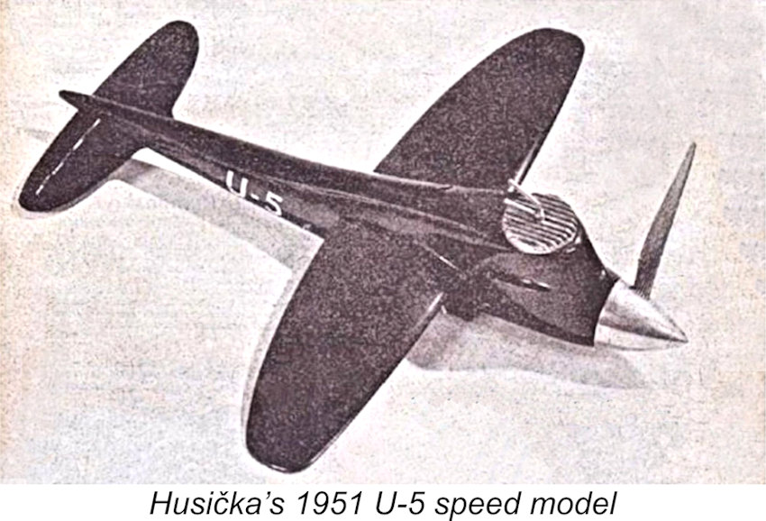
 1952 at Ostrava by establishing a new FAI international speed record for the 2.5 cc class at 156.75 km/hr (97.4 mph). He then went on to win the 1952 Czech championship for the second straight year at an even more impressive speed of 164.47 km/hr (102.2 mph), thus topping his own existing record. Some going in 1952 for a 2.5 cc radial-port diesel!
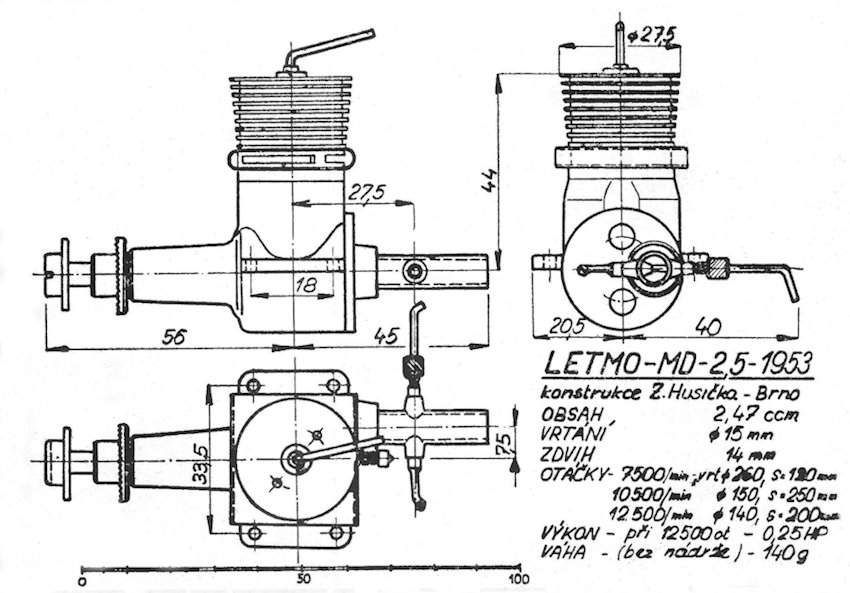

 in Moscow. Zatocil's winning speed of 200.03 km/hr (124.3 mph) placed him ahead of the Hungarian representative Geza Egerváry, who used an American Dooling .29 in his model. This was a notable achievement less than twelve months after the Centre's establishment, although Zatocil's speed fell well short of the Dooling-powered speed of 137.9 mph recorded by 1954 World Champion Bob Luckner of the USA.
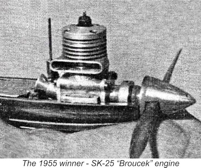 By mid-1955 the new MVVS 2.5 cc engines had reached the stage at which the MVVS team felt ready to challenge the best that the rest of the world had to offer. Accordingly, designer Josef Sladký showed up at the 1955 Control Line World Championship meet in Paris with a model powered by his one-off MVVS SK-25 "Broucek" powerplant, using which he walked away with the top honours in the Speed category. Sladký’s winning speed was 180.24 km/hr (112 mph) - a fine performance by the standards of the day for a 2.5 cc model and a notable improvement over his earlier showing at the Spring meeting in Prague using the S-25 design.
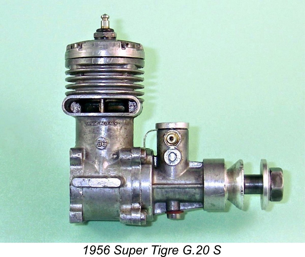 This result must have been a bitter pill for the favored Italian team to swallow. The Italians did manage to occupy the next three places using tuned prototypes of the lapped piston
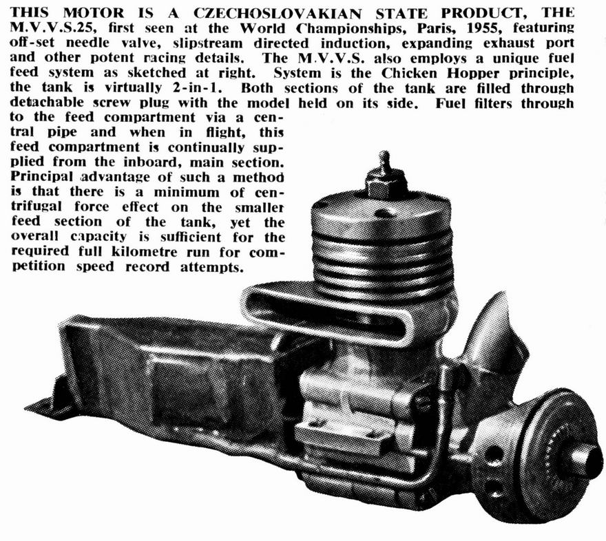
 Additional competition was forthcoming from the Italian
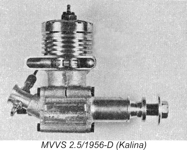
 However, a need was now perceived for the production of more affordable engines of similar design for the use of a larger spectrum of aspiring flyers in order for them to gain the experience necessary to challenge for positions on the Czech team.
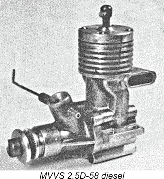 Throughout the period just described, the MVVS center had focused much of its attention upon the development of glow-plug engines for all-out speed work. This changed in 1957, when MVVS commenced the design of what was to become the MVVS 2.5D-58 diesel, developed primarily for free-fight work in which diesels still predominated due to their higher torque being favored by the rules then in force. But that's another story, to be told elsewhere ……………..
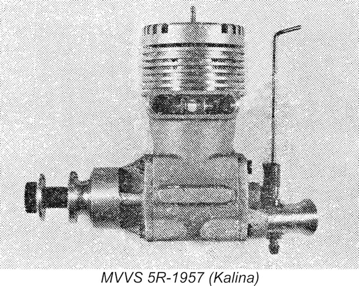
 Returning to 1957, more or less concurrently with their development of the 5R-57 experts-only 5 cc racing engine, the MVVS Centre undertook the development of a 5.6 cc stunt motor which used many of the components of the companion 5 cc speed engine. Unusually for a stunt motor, this new model employed a disc rear rotary valve made of a Tufnol-like material. It utilized the same Dooling-style crankcase casting and twin ball-race front bearing unit as the 5R-57, also retaining the lightweight ringed alloy piston and rear disc valve of the 5 cc racing model.
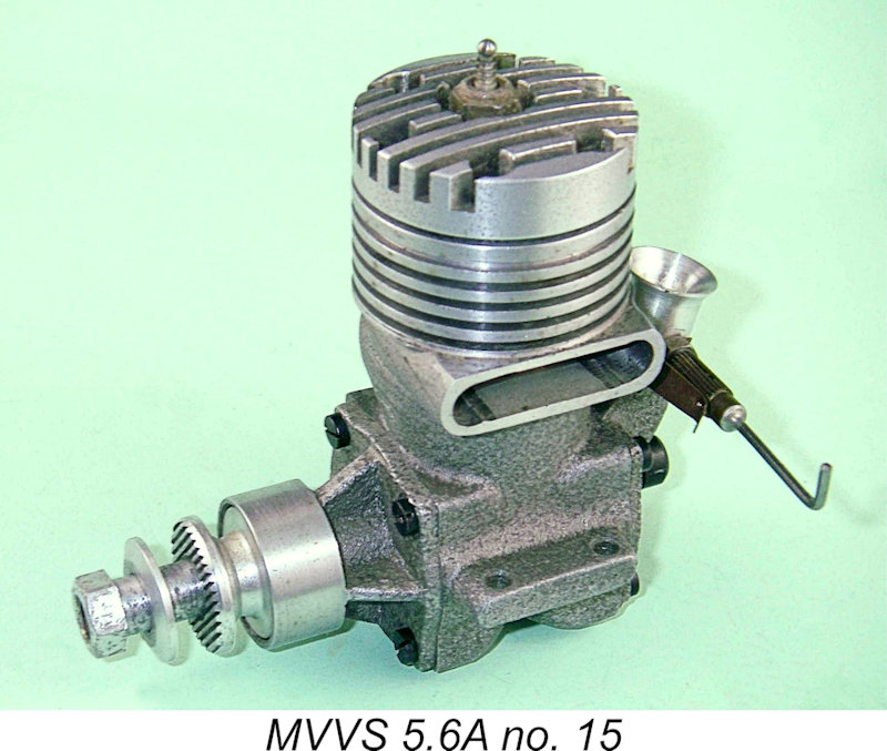
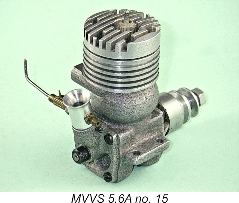 The 5.6A also appears to have been supplied by the factory with its exhaust stack on the left-hand side (looking forward in the direction of flight). Period photographs clearly show that the engine used successfully in international competition by Czech stunt expert Josef Gabris featured that orientation, as does my own LN and apparently unflown example. Furthermore, the example tested by the staff of “American Modeller” magazine in 1962 (see below) also had its stack on the left.
 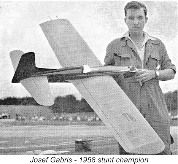 The MVVS 5.6A had an outstandingly successful international debut, being used by Josef Gabris of Czechoslovakia to win the stunt category at the 1958 Expo International meeting at Brussels, flying against the best that the rest of the world had to offer. The engine subsequently joined the 25-D diesel and 2.5R-58 glow models by being put into small-scale series production for wider distribution beginning in 1959. It remained a favorite among leading Eastern European stunt flyers for several decades. Along with a string of consistently high placings during the intervening years, Gabris won a pair of consecutive World titles in 1966 and 1968, still using the same engine.
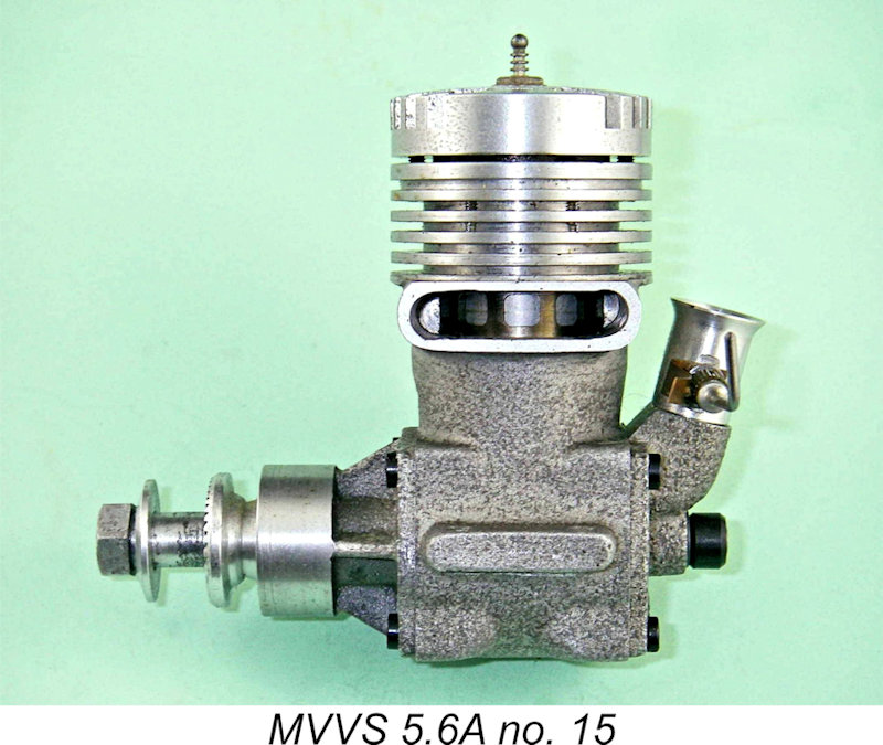 By any objective standard, the MVVS 5.6A must surely be viewed as one of the all-time great stunt motors. The Fox 35 is traditionally seen as the most successful stunt motor of them all, and in terms of widespread usage it richly deserves that accolade. However, if success at the international level over an extended period of time is your criterion, then the MVVS 5.6A offers a very strong challenge to the Fox. To remain competitive at World Championship level over a period of almost 20 years during a time of rapid engine development represents an outstanding achievement by the 1957 MVVS design team.
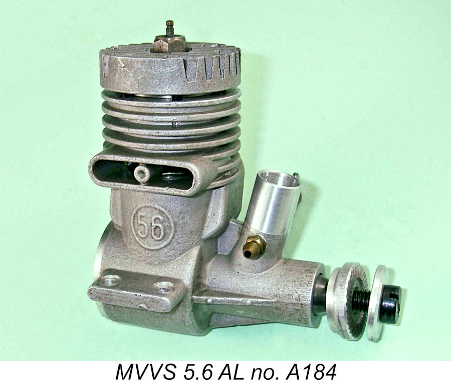 In 1960 the 5.6A was joined by the initial prototypes of a new model called the MVVS 5.6AL. This was a far simpler design which abandoned the ringed piston and rear disc valve induction of the 5.6A in favour of a lapped piston set-up (hence the L), along with the use of crankshaft front rotary valve induction. It also pointed the way to the future by adopting the same twin opposing reverse-flow transfer system that had been pioneered by
  The MVVS 5.6A was the subject of a 1962 test by the staff of “American Modeller” magazine. Although not named, the tester was almost certainly
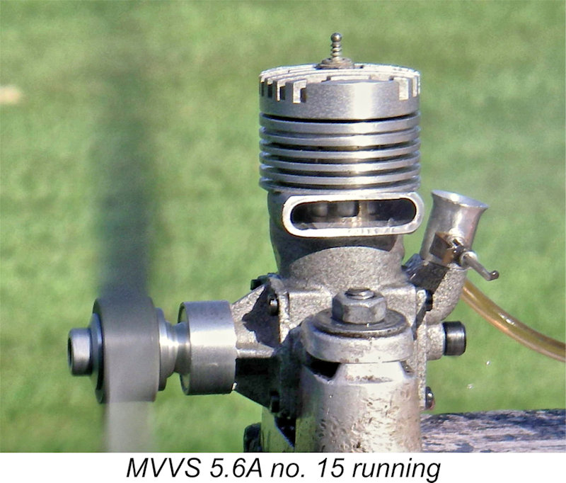
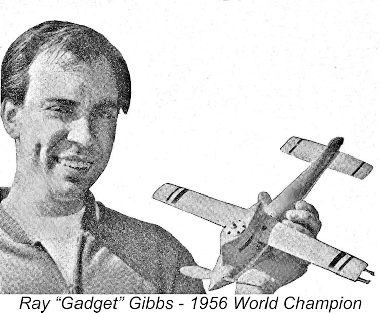 Although the MVVS 2.5/1956-D had done very well at the international level in 1956 and had remained ahead of the Super Tigre opposition, it had still finished behind the individually-constructed specials used by Ray "Gadget" Gibbs of Great Britain and Miclos Vitkovics of Hungary as well as the factory-tuned Barbini B.40 of Italy's Giovanni Cellini. Clearly there was a need to up the ante still further if MVVS was to return to the top of the results sheet in 1957.
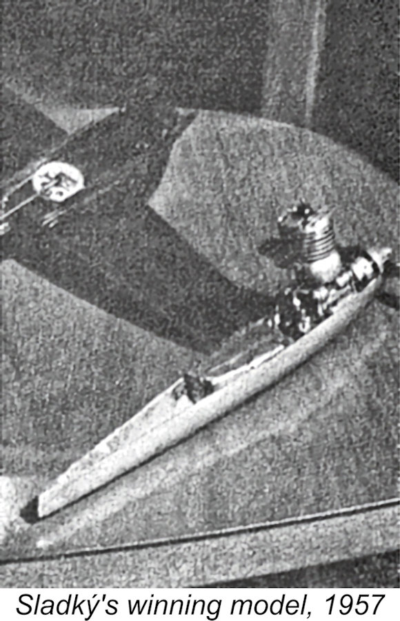 Cobbled-up it may have been, but there was no doubt at all regarding the effectiveness of this design change. At the 1957 Control Line Speed World Championships held in August 1957 at Mlada Boleslav near Prague, Czechoslovakia, the MVVS-powered home team simply pulverized the opposition, taking the individual title courtesy of Sladký's 216.00 km/hr (134.22 mph) effort as well as four of the top five placings. The sole top-five intruder was the fourth-placed Hungarian Gyula Krizsma, still using his own
 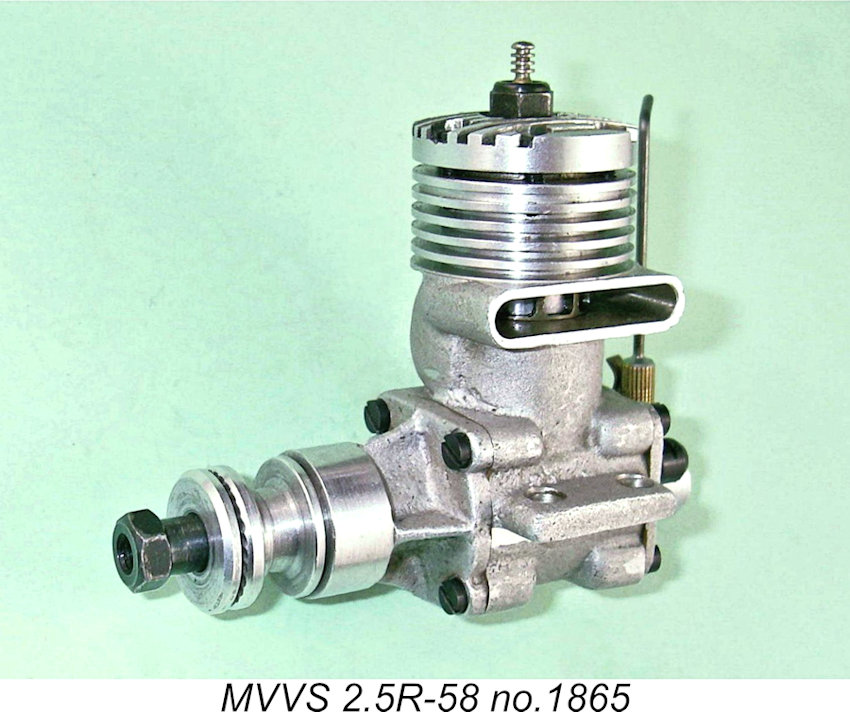 Whatever its true output, there was no denying the overwhelming success of the new design. However, there were clear signs that this dominance would not long go unchallenged. An event which must have given the MVVS designers some pause for thought was the July 1
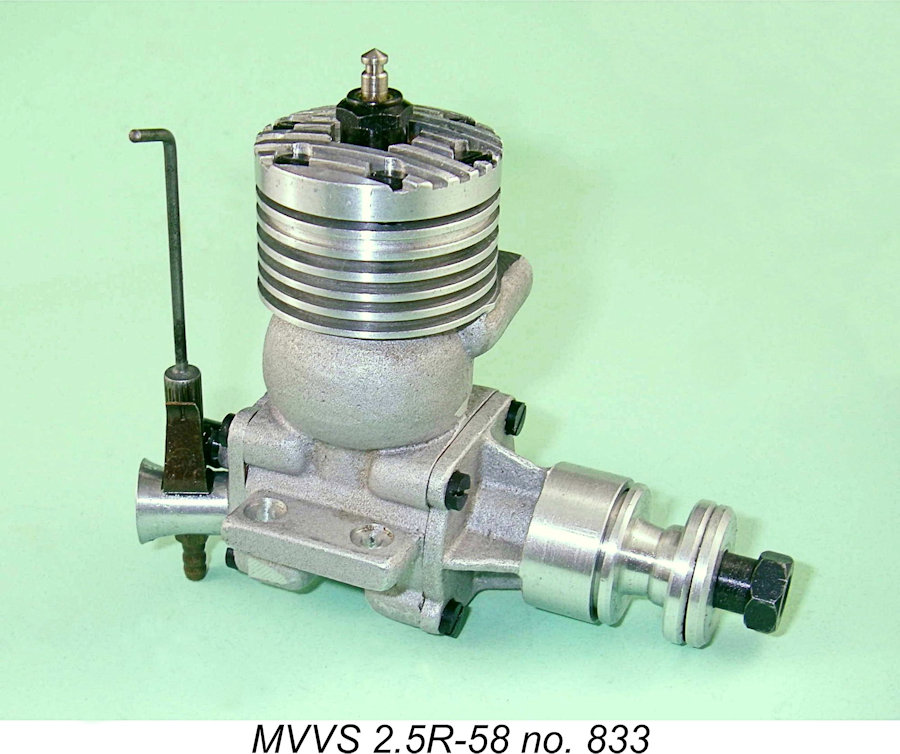 The establishment of the MOKI Institute came too late for the development of a new MOKI design to overcome the MVVS juggernaut in 1957. However, it was clear that this would be very far from the case in 1958 - further development of Krizsma's 1957 engine by MOKI would undoubtedly result in a highly competitive contender in 1958. Not only that, but Super Tigre were not standing pat - they had their lapped-piston version of the G.20/15 well sorted and were now experimenting with the use of crankcase pressure fuel feeds which would allow them to use larger carburettor throat areas and thus further improve an already strong performance.
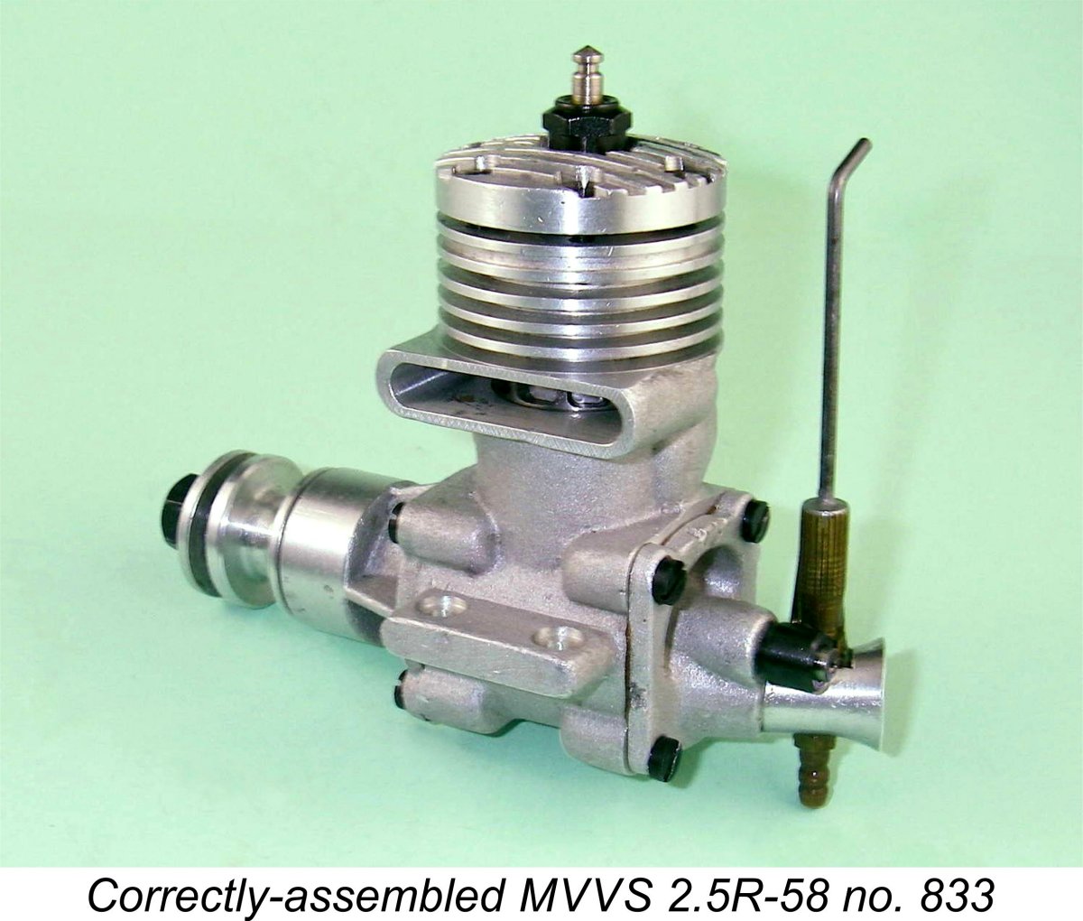 When confronted with one of these engines, one notices immediately that it follows the lead of several earlier Czechoslovakian designs in reverting to the "bulge bypass" set-up derived from the Dooling 29, a system which had been used by MVVS on their larger glow engines since 1954 and applied to their 1957 2.5 cc World Championship winner. However, the most intriguing thing that draws one's attention when examining this engine is the very unusual position and orientation of the intake venturi. The same unusual orientation had been featured in the design arrangement of the MVVS 5R-57.
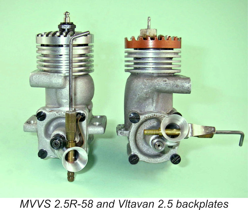 The origin of this rather odd intake orientation becomes apparent when one looks at the rear view of this motor alongside that of the contemporary
 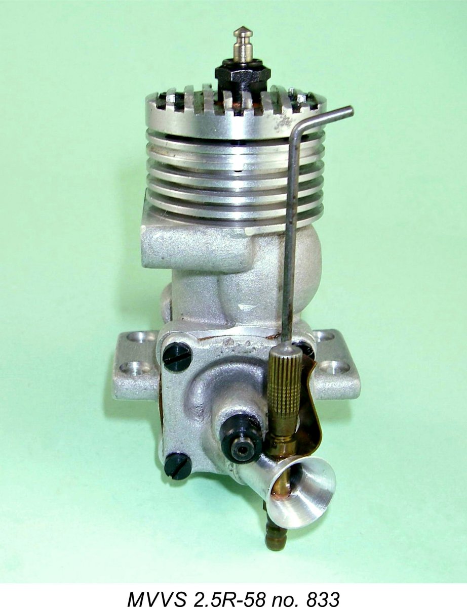 The requirement is met through the provision of extremely large ports in the piston skirt which correspond to similar ports in the cylinder liner at and around bottom dead centre. These liner ports are in turn aligned with the lower portion of the bypass cavity. This arrangement ensured excellent communication between the crankcase interior and the bypass passage at all times when the transfer ports are open. However, it necessarily results in a piston from which much of the skirt on the transfer side has to be removed. In the case of the MVVS engines (and their Vltavan derivatives), these skirt ports were very large indeed, eliminating even more of the piston skirt than usual on the transfer side, to the point where there was virtually no skirt left!
 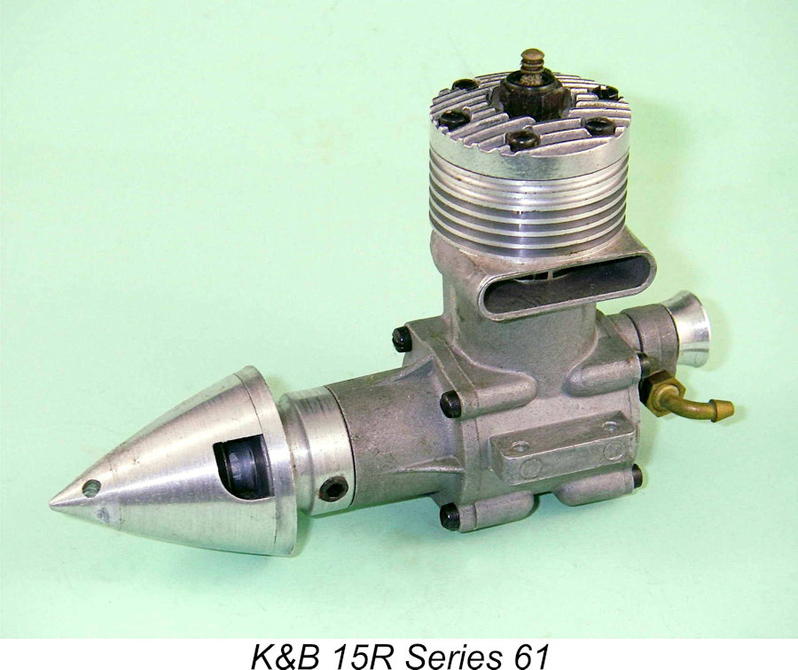 Now in the case of a conventional cross-flow loop-scavenged engine in which the base of the vertical bypass is open to the crankcase, considerations of the swirl effect would seem to indicate that locating the bypass on the left (and hence the exhaust on the right) should take maximum advantage of the swirl effect in an engine having the normal direction of rotation. The fresh charge of mixture will swirl with the spinning crank and head tangentially straight up the bypass in a vertical direction. In fact, one of the first things that most serious users of the K&B Series 61 and Series 64 racing engines did before even running them was to switch the case around to bring the exhaust stack to the right (I know, because I was one of those users!). The left-hand stack location was K&B's trademark "house style", but the right-hand location worked measurably better in practice at higher speeds, for the reasons stated above.
 Clearly, the MVVS designers thought this through very carefully and concluded that the location of the exhaust stack on the left side of the engine was both mechanically desirable and more efficient in term of the gas transfer from the case to the cylinder. Decision taken ............photographs of Sladký's 1957 winning engine clearly show that this stack orientation was undoubtedly applied to the team engines.
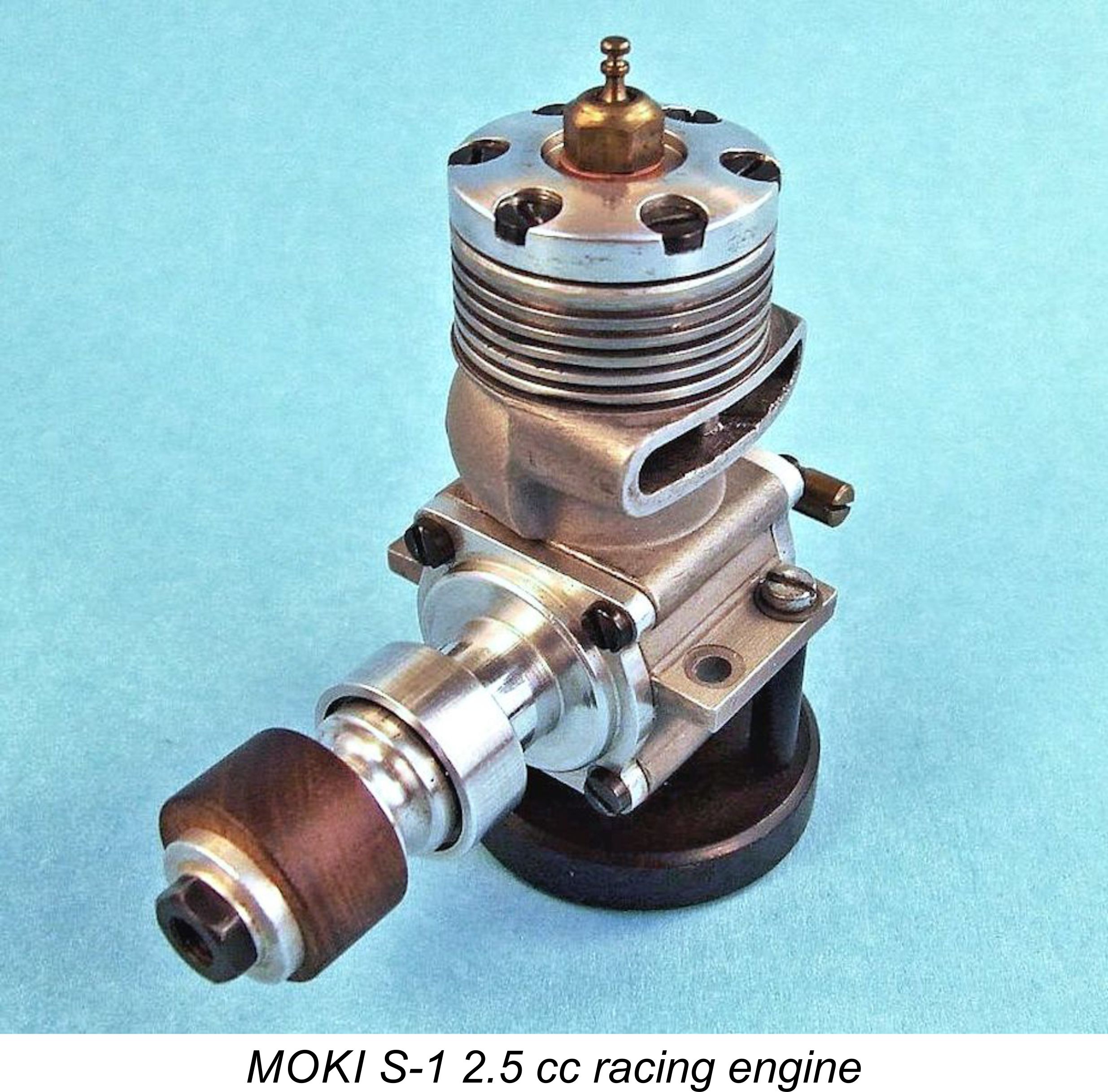 Based upon the above line of reasoning, I have little doubt that the orientation of the case with the exhaust on the left was an intentional and well thought-out element of the design and that the unusual location and orientation of the intake were intended to maximize the engine's efficiency in moving the fuel mixture from the point of entry into the bypass, cooling the piston along the way. In effect, MVVS were trying to maximize the contribution of crankcase swirl to the overall pumping efficiency of the engine, as well as trying to promote improved piston cooling. They were also improving the engine's mechanical integrity.
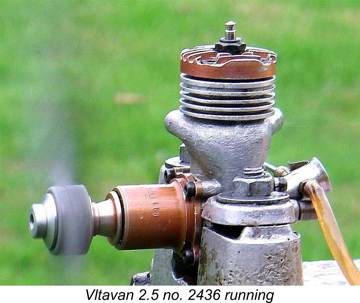 While the MVVS factory specials were continuing to make a strong showing in international competition as of 1958, the same could not be said for the MVVS-based Vltavan clones which were manufactured quite independently in Prague. Although those engines ran well and doubtless provided a wider circle of aspiring Czech modellers with the opportunity to gain valuable experience, the Vltavan name was conspicuous by its absence from contemporary international contest results sheets.
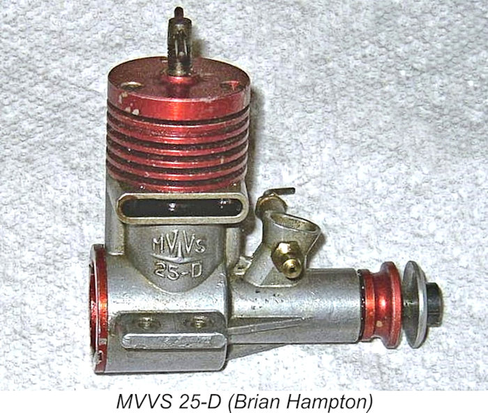 Accordingly, it was in 1958 that MVVS took the first steps towards becoming a major commercial supplier of high-quality competition model aero engines to modellers in general rather than to a few selected experts. They took on a number of extra workers at the centre and added more production equipment. Once this was done, several of their engines were put into small-scale production for wider distribution than had formerly been possible.
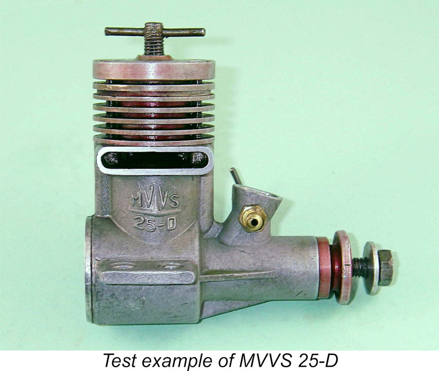 yet produced", reporting an output of 0.295 BHP @ 15,800 RPM - an outstanding figure for a plain-bearing diesel in 1958.
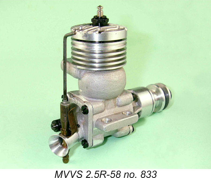 It's important to note at this point that the engine
 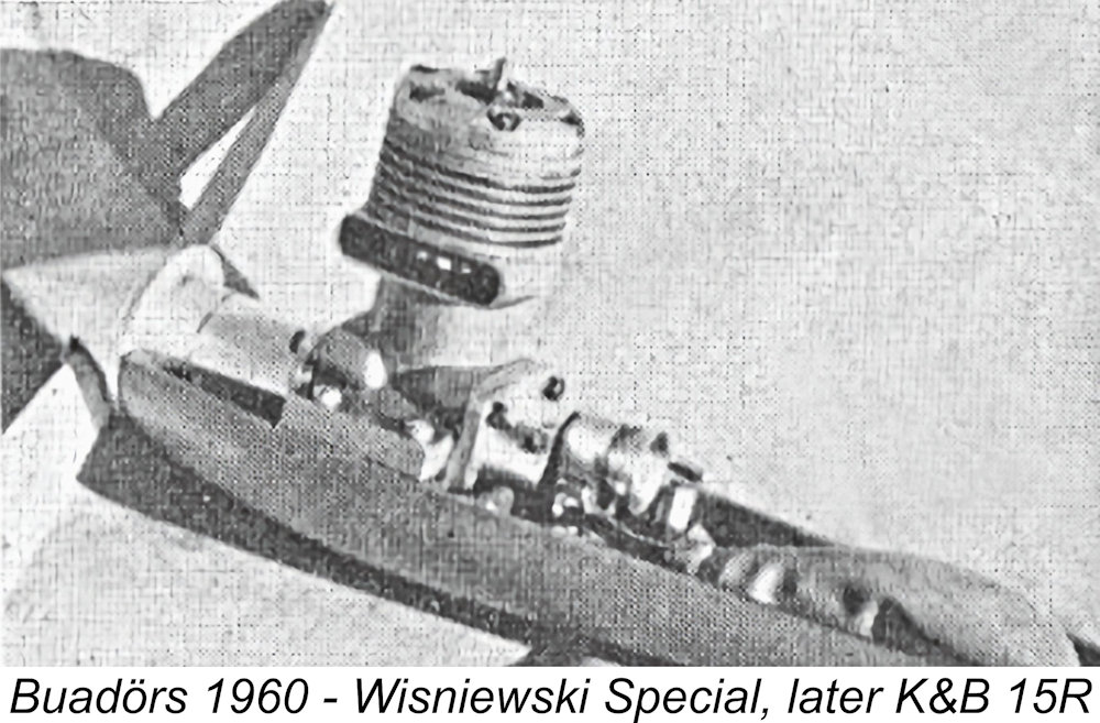 Of course, the joker in the pack at
 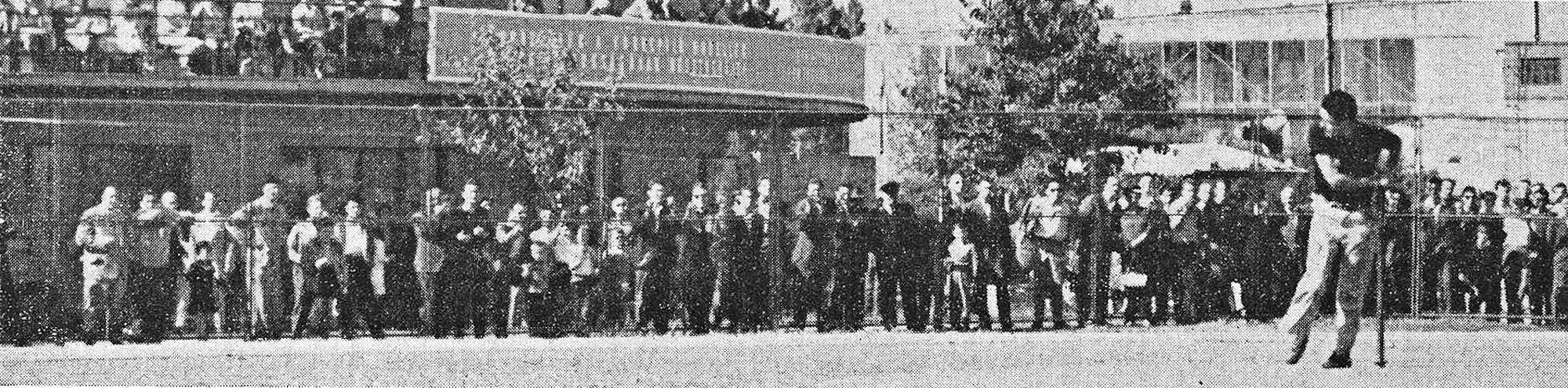 was inexplicably allowed to stand despite having been produced by flagrant line-shortening in clear contravention of the rules (as proved by numerous photographs), Pech would (and therefore should) have finished second behind the moral victor Bill Wisniewski of the USA.
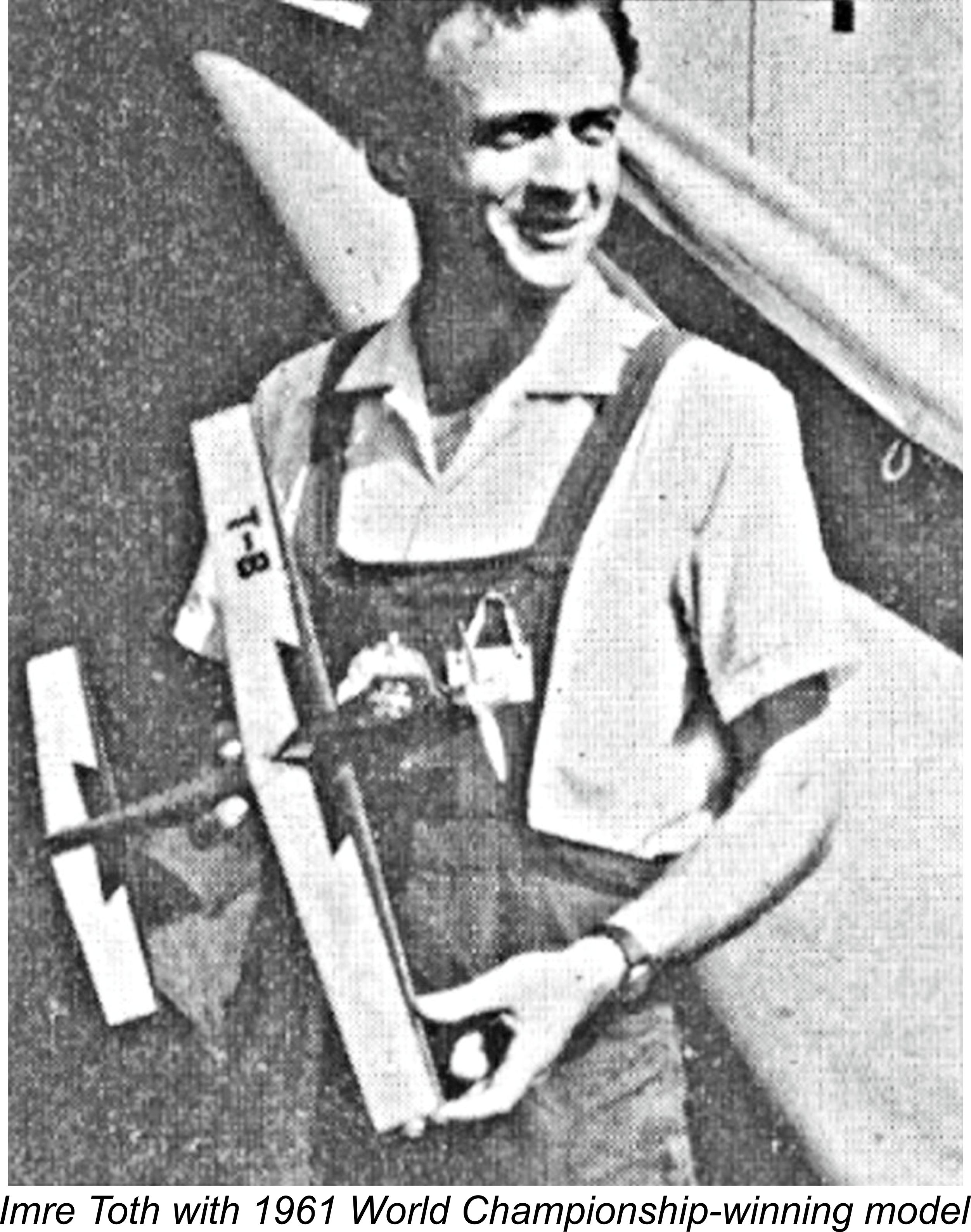 A surprising number of MVVS 2.5R-58 engines appeared in the following year at the 1961 Criterium of Aces meeting in Belgium in the hands of flyers from Sweden, Belgium, Switzerland and Germany in addition to the 2.5R-59's still being used by the official Czech team. However, speeds had dropped a lot by then in view of the new FAI fuel restriction requiring a straight methanol/castor blend. Zbynek Pech's second-place speed of 201.2 km/hr (125.0 mph), only just behind Imre Toth's winning 202.3 km/hr (125.7 mph) figure with his MOKI, highlights the effect which the new fuel restrictions had had on performance. The eventual return to the speeds seen in 1960 had to await the mid-1960's
 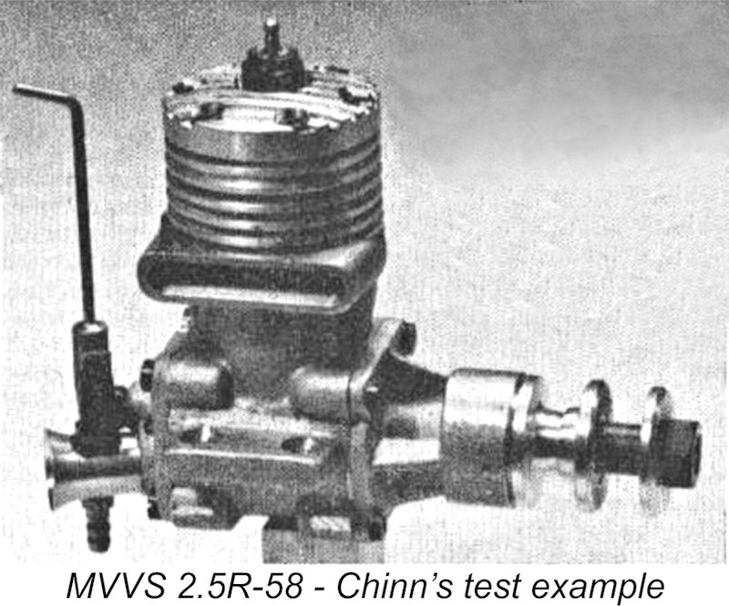 When we look at the illustrations which accompanied Chinn's test, we notice that the example tested by him had its exhaust stack switched over to the right! As discussed earlier, these engines never left the factory set up in that manner - see pages 122 and 140 of Kalina's book, and note also my own "untouched" examples illustrated in the attached photos as well as contemporary photos of the engines in use during their heyday. Both the MVVS 5R-57 and the 2.5R-58 were similarly set up, presumably for the very good and sufficient reasons noted earlier.
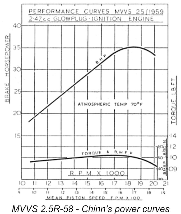 If my previous analysis of the basis for the orientation of the engine's major components is correct, then reversing the case as on Chinn's test example would completely negate the effectiveness of the induction and transfer design as well as being a retrograde step in mechanical terms. Once we accept this, Chinn’s failure to achieve the claimed level of performance from his test example of this engine becomes completely understandable. He obtained the still-creditable figure of 0.35 BHP at 18,500 rpm on 40% nitro, whereas the factory claimed 0.38 BHP at 18,500 rpm on 45 % nitro for the series-production version of the engine. Pretty close, admittedly, but perhaps the orientation of the cylinder made just that little bit of difference ..................
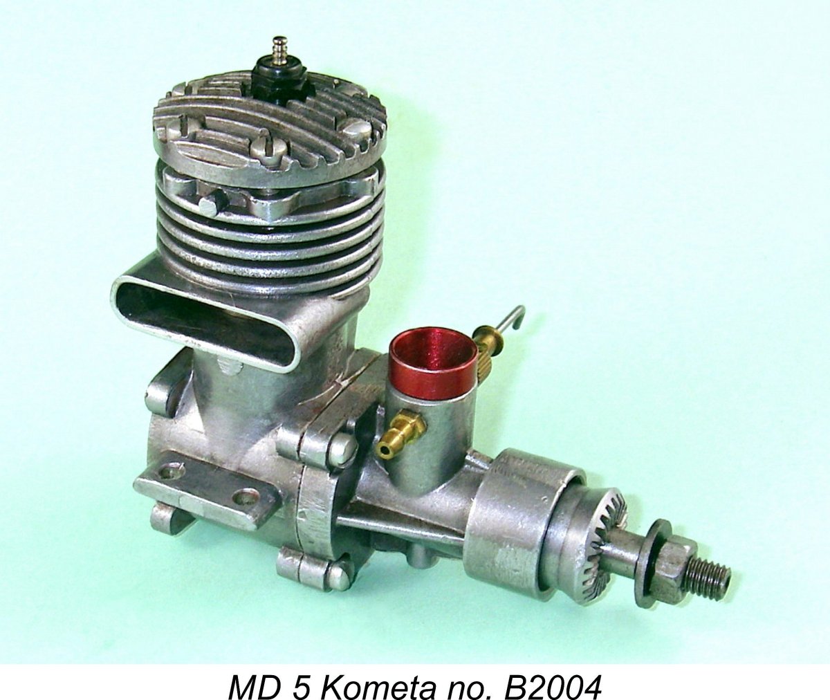 At the time in question, the Russians were beginning to take a strong interest in aiming for top honours in the international modelling field themselves. Like the Czechs before them, they decided that one of the elements of a successful training program for Russian competition flyers would be the provision of readily-available engines with which these flyers could gain experience.
 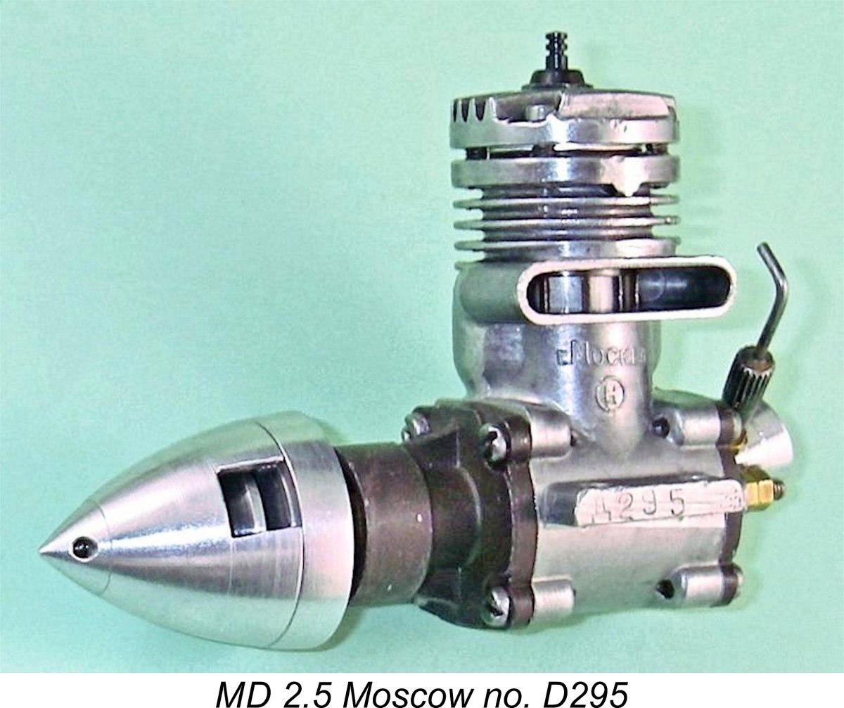 In 1960 the Kometa was joined by a copy of none other than the MVVS 2.5R-58. Presumably this arose from the fact that members of the USSR team had used MVVS engines with some success from 1958 through 1960 and were thus very familiar with the design. The new Russian production was designated the
 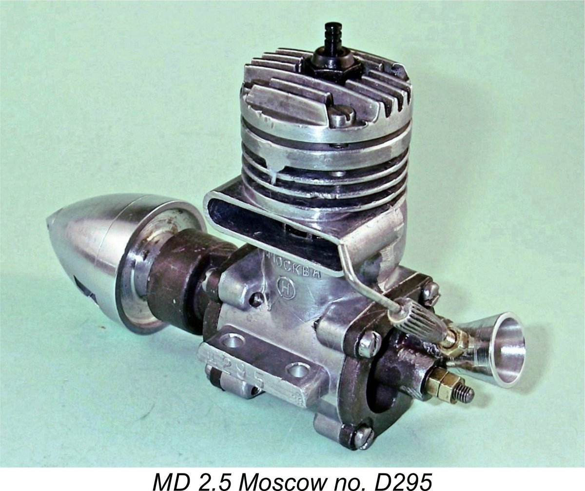 The MD-2.5 design differed in a few respects from that of the MVVS, few of them positive. The intake was more conventionally and hence conveniently oriented for mounting, but the intake venturi was not positively secured in any way, merely plugging tightly into its housing in the backplate! The exhaust stack was oriented to the right as supplied - again a retrograde step in some ways, as I hope I’ve made clear. The disc valve was made from aluminum instead of cast iron, a clear step backwards. The individual components were generally quite well made but were very poorly matched and fitted. This was of course a guarantee of sub-standard performance in a design which depended overwhelmingly upon precision of construction to realize its full performance potential.
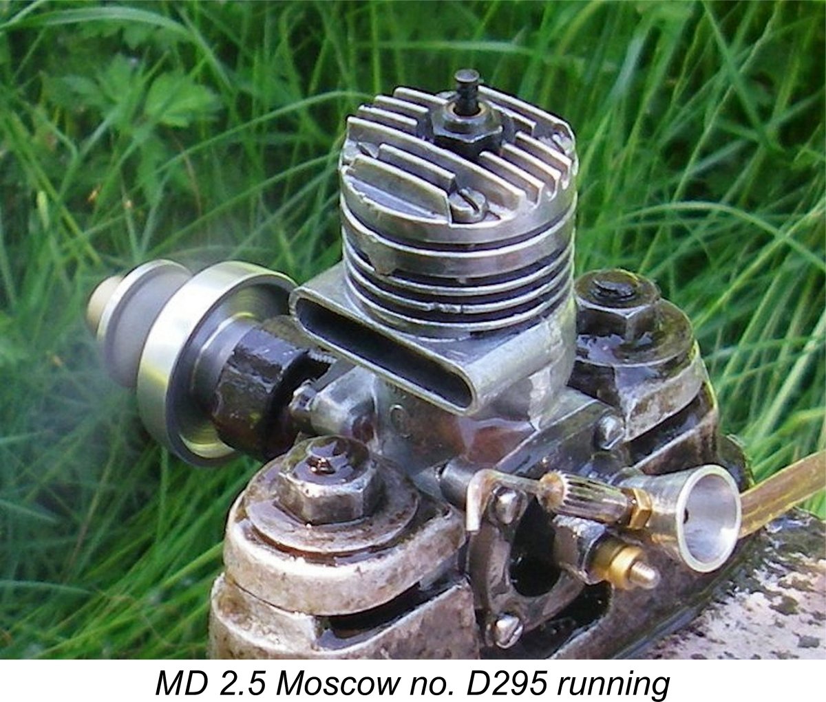 Given the MD-2.5’s design heritage, it has always seemed to me that the claimed level of performance might well have been possible with an example which was carefully assembled from selected components. To test this theory, I went through my own example, reversing the stack orientation and ensuring that the engine was properly put together. However, all original components were retained. Although the seal provided by the rings was admittedly less than perfect, it was more than adequate for easy starting and improved further with some running time as the rings bedded in. Running on 30% nitro, the engine delivered a measured 0.295 BHP @ 17,200 RPM, more or less exactly as claimed by the manufacturers.
 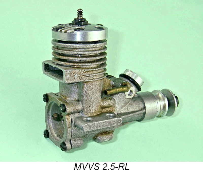 performance were rising at a very rapid rate during the period covered by this article. The 1961 introduction of the K&B .15R Series 61 and the Super Tigre G.20/15 had already raised the bar, and a lacklustre performance by the Czech team at the 1962 World Championships at Kiev made it obvious that the competitive days of the MVVS 2.5R series were numbered ......................
| |