
|
|
Forgotten Danish Classic - the Mikro 5 cc Racing Engine By Adrian Duncan with Jens Geschwendtner
Even some companies which focused for the most part upon the manufacture of sports engines have at least toyed with the idea of developing a high-performance model. In England, E.D., AMCO and Davies-Charlton all entertained thoughts of such a product, although apart from the famous E.D. Mk. III “Racer” of 1951 none of these ever came to fruition. However, some such manufacturers did follow through on their racing engine ambitions. In Japan, companies like O.S., K.O., Fuji, Enya, Mamiya and Hope all developed racing models during the early post-WW2 years. However, their stories form separate topics. Here I examine a racing engine from a small Danish manufacturer who had previously specialized in the small-scale production of simple sports diesels. In an earlier article on this website which covered the early post-WW2 Danish model engine manufacturing industry in general, I included a brief summary of the history of the Mikro range. Here I’ll focus upon what was in my opinion the In undertaking this task, I’d like to make it very clear that I couldn’t even have got to first base on this topic without the invaluable assistance of my good Danish friend Jens Geschwendtner, who interviewed Mikro manufacturer Kai Nielsen in 1979, thus preserving much historical detail concerning the Mikro range which would otherwise have been lost. Moreover, quite apart from sharing his wealth of knowledge with me, Jens also made a fine example of the Mikro 5 cc racing engine available to me for examination and testing. It’s really hard for me to adequately express my appreciation for his contribution. This article is as much Jens' work as mine - I merely held the pen. I'd also like to acknowledge the help and encouragement freely provided by Jens' long-time team race partner Luis Petersen. There's no way that an "outsider" like me could have generated an article of this sort without such unstinting assistance from colleagues who are "on the spot" and speak the language. Thanks, Luis! Now, on with our tale! I’ll begin by summarizing the circumstances which led up to the appearance of this fine model engine. Background
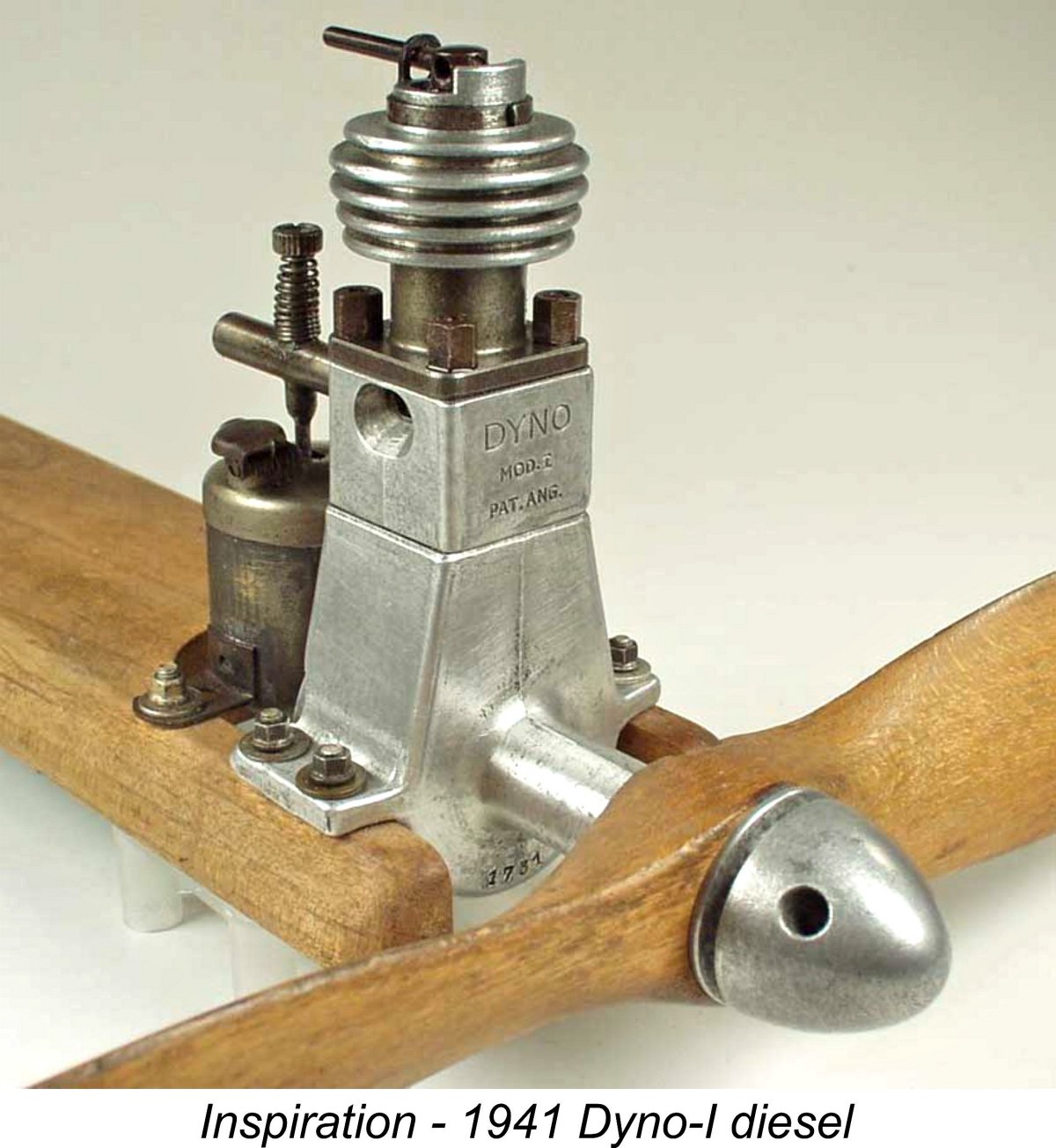
The idea of Neilsen producing a model diesel apparently stemmed from the initiative of one of his employees, who showed up at work one day in 1944 with a Swiss Dyno diesel which he had somehow obtained despite the fact that Denmark remained under German wartime occupation at this time. Nielsen was always open to suggestions for new product lines, and this one evidently appealed to him. Drawings were immediately commissioned so that production could get started. The result was the first Mikro model engine, the company’s 2 cc Mikro-I sideport diesel. Like most of the model diesels which appeared at this time, the original Mikro model was basically another Dyno clone, evidently owing much to Ivan Rogstadius’s published plans which had appeared in the Swedish technical magazine “Teknik för Alla” beginning in late 1943. It weighed in at 220 gm (7.76 ounces) and developed a claimed 1/10 BHP @ 7,500 RPM - a quite credible claim.
A very neat feature of this engine was the wire clip which circled the top of the cylinder head and had a vertical extension which engaged with the compression screw lever. This was a very simple and effective means of discouraging the comp screw from running back during operation. I've applied it with success to the Speed Demon 30 diesel from America, which inherently suffered from chronic compression run-back. Later versions of the Mikro showed a few detail changes. Perhaps the most unusual of these changes was the addition of a pair of lubrication cups to the main bearing – seemingly the designer was not convinced that the front section of that bearing would receive sufficient lubrication from the oil in the fuel alone, particularly given the weight of the flywheel which was fitted to many of these engines for tether car service. The revised version was also provided with a streamlined metal back tank in keeping with a then-current design trend in Denmark.
It appears that Kai Neilsen did not pursue the manufacture of the Mikro diesel with any great vigour, evidently seeing it as a sideline to his other work programs. Only around 250 examples of the original sideport Mikro-I model seemingly ended up being completed over a period of several years, presumably being produced in small batches when pressures of work relating to other projects allowed this. The competing Thorning III 2.41 cc diesel from Helsingør (in English, Elsinore) was made in substantially larger numbers, hence becoming Denmark's most widely-used model engine for some years. That story too has been recounted in detail elsewhere on this website. During the production life of the Mikro-I model, a number of improvements of the company’s own devising were carried out. These included a switch from a machined barstock crankcase to a casting as well as the use of a drop-forged connecting rod made in England to replace the original machined bar-stock component. The company’s model-related activities were not confined to engine manufacture. A range of accessories was also produced under the Mikro name, including very high quality wheels for model racing cars and blanks for aircraft propellers.
Quite apart from the emerging domestic competition, the Danish market was then just beginning to open up to imported model engines from other Scandinavian countries as well as England and Italy. This placed Danish model engine manufacturers under great pressure to develop new updated models which could compete with the imports. Nielsen’s response to this challenge was to develop a completely revised 2 cc design. In 1948 the original 2 cc Mikro-I sideport model was replaced by a 2 cc Mikro-II model featuring crankshaft front rotary valve (FRV) induction and a stepped piston to facilitate transfer. The stroke was reduced, being set at 15 mm to go along with a 13 mm bore. This engine was apparently designed by an engineering colleague of Neilsen's named Henriques.
Design revisions were soon put in hand to address these issues, the result being a much improved version of the Mikro-II. However, the damage to the engine's reputation had already been done. A planned production series of 1,000 units was apparently started, but only about 300 examples ended up being completed. Apart from its slow sales, another reason for the abandonment of the 2 cc diesel project after its problems had been addressed was the fact that Danish model tether car racers (of whom there were apparently still many at this time) were This challenge clearly appealed to Nielsen, who in 1950 became the sole Danish model engine manufacturer to respond to this demand. Once again he engaged the services of his engineering colleague Henriques to design the engine. Seeing no point in re-inventing the wheel, Henriques quite logically elected to draw upon the design of the best 5 cc racing engine on the market at that time – the Dooling 29 from America. He somehow managed to obtain an example of the Dooling and set to work. The result was the central subject of this article – the Mikro 5 cc racing glow-plug engine. Let’s have a close look at this interesting but little-known powerplant. The Mikro 5 cc Racing Engine – Description
That having been said, there were certainly a few very marked similarities. Nominal bore and stroke of the Mikro were 20.0 mm (0.787 in.) and 15.5 mm (0.610 in.) for a displacement of 4.87 cc (0.297 cuin.). These very over-square figures were obvious reflections of the comparable bore and stroke numbers for the Dooling of 20.32 mm (0.800 in.) and 15.09 mm (0.594 in.) for a displacement of 4.89 cc (0.298 cuin.). The Mikro had a bore/stroke ratio of 1.29:1 as opposed to the Dooling figure of 1.35:1, hence being slightly less over-square, but the influence is unmistakable. The use of a very large bore with a short stroke has both pros and cons. On the plus side, the greater cylinder circumference allows for the provision of cylinder ports having a greater area. The larger bore also provides greater piston wall area to resist side loadings during operation. Furthermore, the shorter stroke reduces piston speed for a given rotational speed, theoretically reducing both piston/cylinder wear and the engine's tendency to generate vibration during high-speed operation. However, a very short stroke also tends to reduce the engine's torque development potential. Accordingly, exaggeratedly-over-square bore/stroke dimensions are really only suited to engines which are intended to operate at high speeds. The implication is that like the Dooling, the Mikro was undoubtedly intended for high-speed operation.
Although many owners seem to have reversed the Mikro’s stack orientation, it appears that the engine was actually supplied with the stack oriented to the left (looking forward in the direction of flight). As I discussed in my earlier article on the subject of the similarly-ported MVVS 2.5R-58, there were several compelling reasons for this orientation. For one thing, the Dooling system necessarily results in a piston from which much of the skirt on the transfer side has to be eliminated. With the exhaust stack located on the right in the conventional manner, the side-load during the power stroke is all directed to the transfer side of the piston. But this side of the piston is extremely poorly equipped to deal with these loads - there simply isn’t much of it left! Not a good situation either for mechanical reliability or engine longevity.
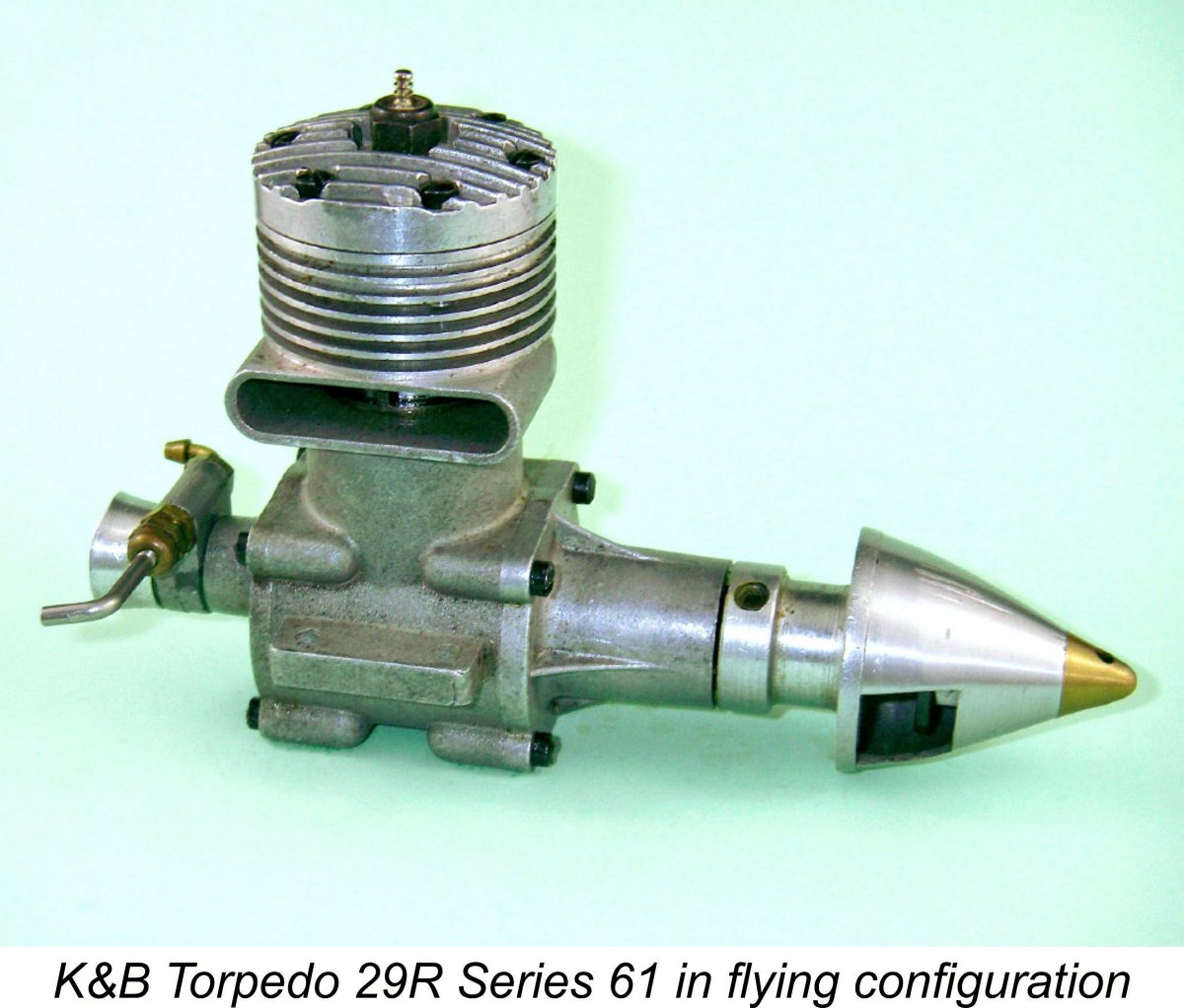
So there's a compelling mechanical argument in favour of a left-side location of the exhaust stack. But what about the possible effect upon transfer efficiency?? Well, if such a relocation of the exhaust stack would have compromised engine performance in any way, there’s no possibility that the designers of the Dooling-style MVVS factory specials of the mid to late 1950’s would have adopted it, as contemporary photographs of their "works" engines like that at the left prove conclusively that they did. They would have accepted that the price to be paid for improved mechanical integrity was simply too high in performance terms. In a World Championship speed context, ultimate performance was the imperative rather than longevity. Accordingly, the performance implications of making this change must surely have been well considered by the World Championship-winning MVVS design team. Here another consideration entered the picture - that of crankcase swirl. The gas in the crankcase of a two-stroke engine does not sit still – it swirls quite strongly in the direction of rotation of the shaft. At the speeds at which racing glow-plug engines were even then operating, gas velocities generated by this swirl effect were quite considerable. Speed engine designers caught on to this fairly early on, beginning to plan their engines to maximise the positive effect of crankcase swirl on the transfer process. It appears that engineer Henriques was among the pioneers in this area. It was recognized that the swirl effect imparted considerable velocity and hence kinetic energy to the mixture in the case. There were obvious benefits to be gained from harnessing this energy to help move the gas into the bypass passages more rapidly. This could be facilitated through the appropriate placement and design of those passages. In effect, the crankcase was being seen as a kind of centrifugal pump which could assist in the transfer process (remember, this was well before the advent of tuned pipes!). Now in the case of a conventional cross-flow loop-scavenged engine in which the base of the vertical bypass is open to the crankcase, In fact, one of the first things that every serious user of the K&B Series 61 and Series 64 racing engines did before even running them was to switch the case around to bring the exhaust stack to the right (I know, because I was one of those users!). The left-hand stack location was K&B’s trademark “house style”, but the right-hand location worked measurably better in practise at higher speeds, for the reasons stated above. So the conventional orientation of the cylinder works fine with the typical vertical bypass passage opening directly off the crankcase in the normal manner for cross-flow loop-scavenged motors. But in the case of a Dooling set-up, the mixture enters the bypass more horizontally than vertically, crossing just below the piston crown in order to do so (and thereby contributing very significantly to the cooling of the piston crown). If you think about the swirl effect for a second, it becomes intuitively apparent that a bulge bypass transfer system is best located on the right of the engine! The swirl effect will then throw the gas tangentally straight into the bulge where it is wanted. Clearly, engineer Henriques thought this through very carefully and concluded that the location of the exhaust stack on the left side of the engine was both mechanically desirable and more efficient in term of the gas transfer from the case to the cylinder. He wasn’t alone – contemporary reports and latter-day recollections from the late 1940’s and early 1950’s confirm that many successful users of the Dooling 61 ran their engines with a left-hand stack orientation. Indeed, Tom Dooling himself once endorsed this arrangement during a recorded discussion with a Dooling 61 user, and for the very reasons stated above. Those who ran such engines with a right-hand stack orientation were motivated purely by their sense of familiarity.
This is the most persuasive evidence that we have to support the notion expressed earlier that the primary target market for the Mikro was the model tether car racing field. In that application, weight is far less of an issue than it is in aircraft service. Given the physical stresses which the engine in a tether car must withstand, the over-riding concern becomes strength and durability, and if some extra So where does the extra weight come from? Well, to begin with, the Mikro is built up around an extensively machined and notably massive aluminium alloy sand-casting which incorporates the open-ended crankcase, the bypass bulge, the exhaust stack and the cooling fins in unit. It is topped with a correspondingly massive cylinder head which is also machined from an aluminium alloy sand-casting. Most unusually for an engine of this displacement, this head is secured using no fewer than eight machine screws – more additional weight. An unusually thick fibre gasket is used to ensure a head seal and set the head/piston clearance.
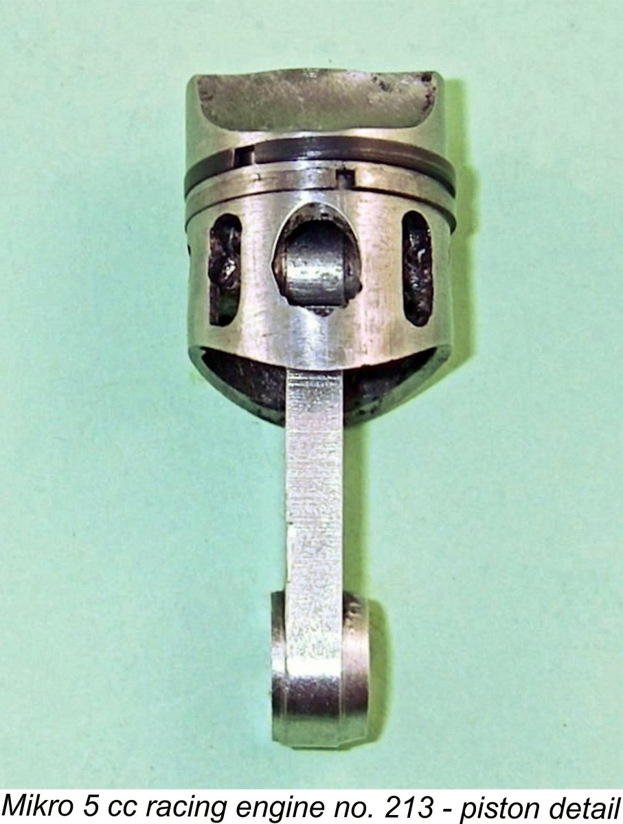
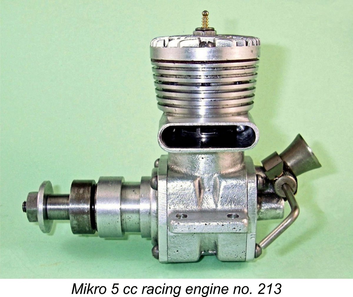
The engine’s port timing is very aggressive indeed. The exhaust opens at only 95 degrees after top dead centre (TDC) for a remarkably long (and in my view perhaps somewhat excessive) exhaust period of 170 degrees. The transfer port opens only some 10 degrees later for a transfer period of 150 degrees. This timing certainly implies that high operating speeds were anticipated. I would also expect this engine to be LOUD!! The piston drives the crankpin through a sturdy con-rod which appears to have been machined from bar stock. The big end bearing is bronze-bushed. The gudgeon pin is fitted with brass end-pads. The very sturdy crankshaft is machined in one piece from steel which is then heat-treated. The crankshaft is carried in two ball-races which are housed in yet another extensively machined aluminium alloy sand-casting. The prop is secured using a steel stud which threads into a tapped hole in the front of the crankshaft. A rather massive steel nut engages with this stud to secure the prop. The sole concession to lightness here is the aluminium alloy prop washer! At the rear, we find yet another substantial sand-casting in the shape of the backplate. This displays more influence from the Dooling 61 than the 29, since it has a downdraft intake. It incorporates a rotary disc valve of aluminium alloy which runs on a pressed-in steel spindle. The timing of the disc valve is highly unusual for a racing engine. The valve opens at 45 degrees after BDC but closes at only 15 degrees after Top Dead Centre (TDC) for a total induction period of only 150 degrees. This timing seems to be more suited to the development of mid-range torque than maximum top-end power. In that respect, it appears rather inconsistent with the engine's cylinder port timing. Perhaps this is another expression of the engine’s intended use as a tether car powerplant. It would of course be very easy to extend the induction period if desired by modifying the aperture in the disc valve itself. However, in the interests of retaining originality, I left well alone for the purposes of this test.
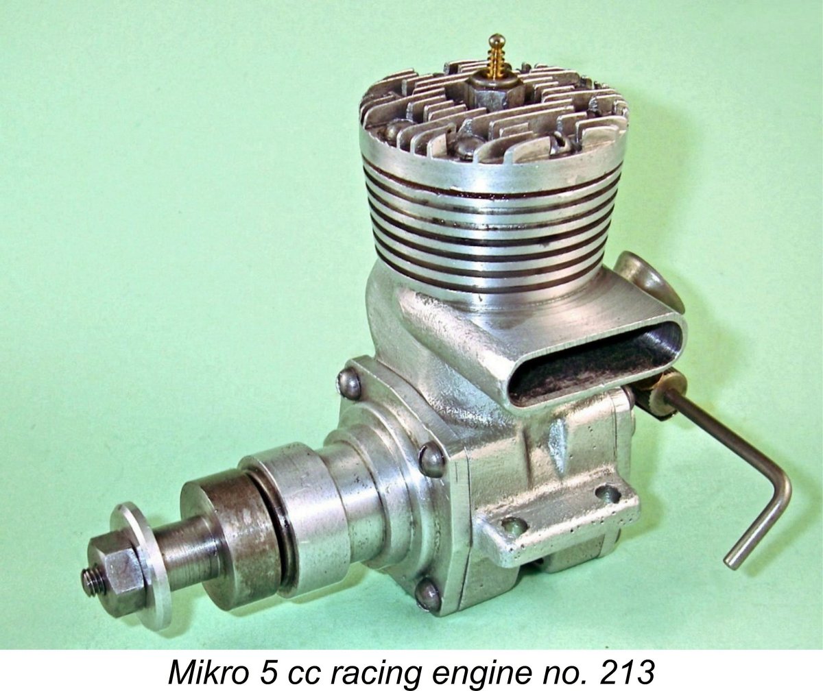
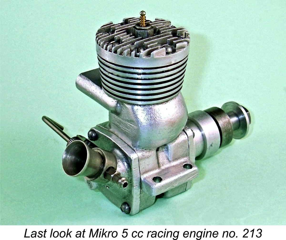
The intake venturi’s nominal bore is a massive 8 mm (0.315 in.), which comfortably exceeds the Dooling 29’s corresponding nominal dimension of 6.98 mm (0.275 in.). The jet extends into the centre of this venturi to maximize the engine’s suction potential. Even so, with a venturi of this size one might expect to have to arrange for some kind of pressure or gravity fuel feed for many applications. My earlier test of the 5 cc MD-5 Kometa racing engine from Russia showed that a 9 mm venturi with a 4 mm spraybar was right at the limit for operation on suction feed on the test bench. An 8 mm venturi minus the spraybar might be expected to behave in a similar fashion. An interesting detail connected with the needle valve assembly is the fact that in addition to the provision of a sturdy two-leaf spring clip to retain needle settings, the outer end of the needle carrier is spit. This feature can be seen in the above image. This measure is clearly intended to stabilize the needle laterally so that it doesn't vibrate when the engine is running. On test, it proved to be extremely effective. Another very unusual feature of the Mikro is the fact that its backplate is secured by only three machine screws instead of the usual four. As can be seen in the above image of the backplate, the design of the intake arrangements did not leave any space to accommodate the fourth screw hole in the backplate. The female hole to accommodate such a screw is drilled and tapped in the main crankcase casting despite this. We might conclude that the manufacturer anticipated that some owners might want to switch the exhaust stack orientation despite the arguments presented earlier against doing this. A noteworthy characteristic is the fact that the installation spigots on both the front housing and the backplate are machined to what is in effect a moderate press fit in the crankcase bore. I had the greatest difficulty in removing the front housing to extract the piston for ring servicing (see below), and I couldn’t shift the backplate at all using “fair” means. Given the fact that racing engines tend to require dismantling more often The Mikro 5 cc model was not provided with any form of identification on the crankcase. The only marking of any kind was a stamped serial number which appeared beneath the left-hand mounting lug. My own illustrated example which was very kindly supplied by Jens Geschwendtner bears the number 213 as illustrated. Jens was also aware of similar engines bearing the numbers 187, 216 and 256. The quality of the engine’s construction is generally beyond reproach. However, although my example had clearly never been run at any time, it displayed unmistakable symptoms of stuck piston rings as received. The application of heat didn’t free things up as it sometimes does, so I took it apart sufficiently to extract the piston so that I could set about freeing the rings manually. Both rings were indeed firmly stuck. The bottom ring freed up after some careful work on my part, but unfortunately the top ring proved to be well and truly stuck in what appeared to be a contaminated section Thankfully, I was able to call upon the ring-making services of Bjorn Baal of RMJ Machine Worx in Farmington, New Mexico, who had then just taken over Frank Bowman’s old ring-making business. Bjorn quickly supplied a very well-made replacement ring which was a perfect fit after I cleaned out the ring groove very thoroughly. This put the engine back into first-class running order. In the past, the Mikro 5 cc racing engine has generally been characterized as a “Dooling copy”. I hope I’ve shown that this was very far from being the case. In reality, the only derivative features which the Mikro shared with the Dooling were its exaggeratedly over-square bore and stroke dimensions and its bulge bypass arrangement. Even the latter feature utilized a very different piston porting arrangement to that of the Dooling. In every other key respect, this was a completely original design. It was also extremely well executed – a credit to its manufacturer Kai Nielsen. OK, fair enough – we now know what the engine looked like and how it was constructed. Next question - how does it run?? Let’s find out!! The Mikro 5 cc Racing Engine on Test Since this was clearly a brand-new un-run engine, it undoubtedly needed a break-in period both to settle the sliding bearings and to bed down the rings. As reassembled, the engine's compression seal was somewhat "leaky", although not in my judgement to the point of creating potential starting difficulties. This is a not uncommon characteristic of ringed piston engines which have had no previous running, since it takes a little running time to bed the rings in properly. In my experience, it doesn't take a great deal of running to get the bedding-in process underway and produce a marked improvement. Even so, just as a precaution I took along some straight castor oil in a syringe to allow the administration of an oil prime in case of difficulty with the initial starts.
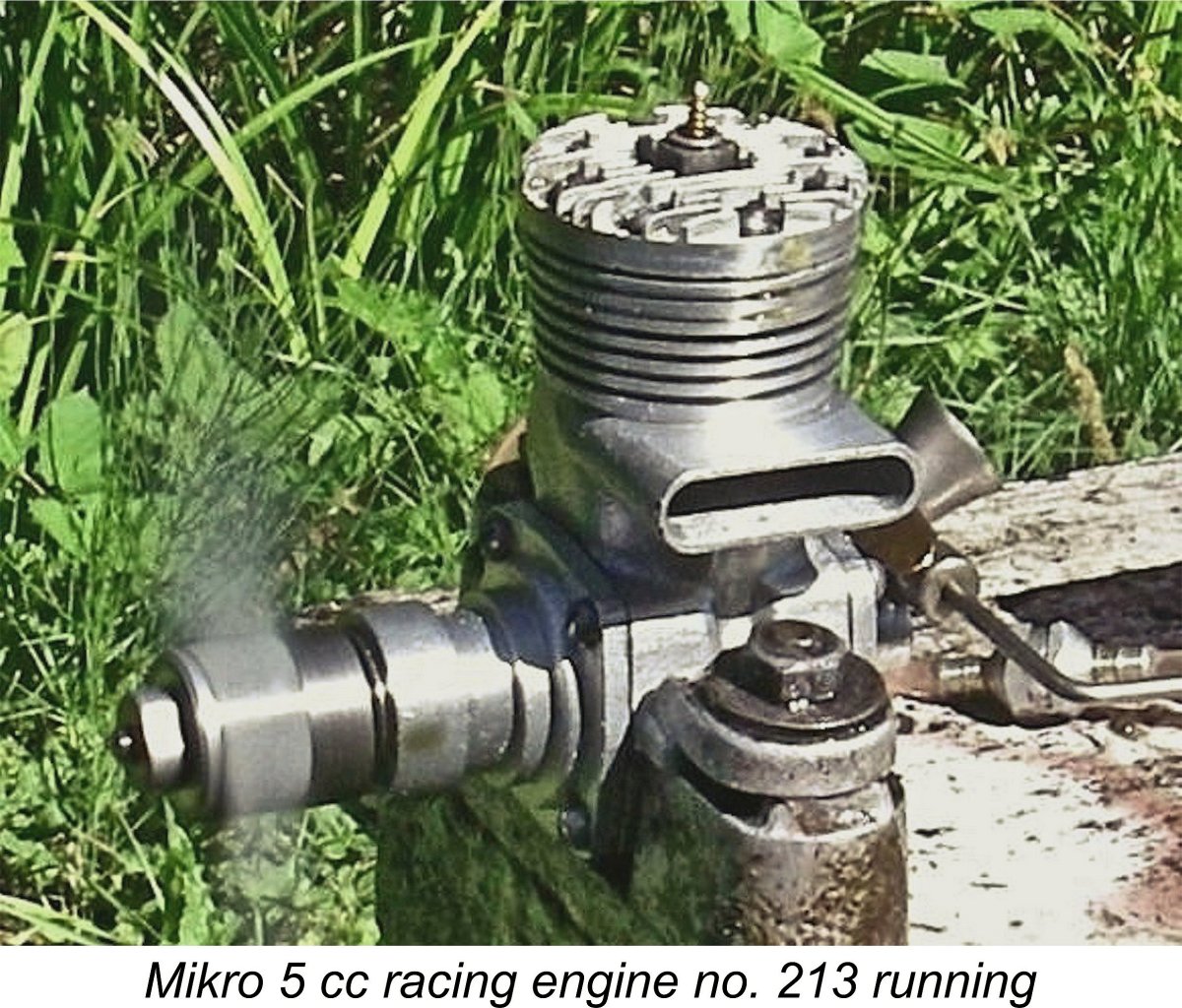
To get the ball rolling, I elected to use an APC 9x5 prop along with an oily moderate-nitro fuel to help with the initial ring seal. I also used a hot plug to assist in starting and rich running. The fuel employed for initial testing had 15% nitro and a 30% castor oil content. Anticipating relatively poor suction, I opened the needle all the way and set the fuel level in the tank at needle valve height prior to getting stuck in. It turned out that the straight castor prime was not required - a prime using the very oily fuel sufficed to create an adequate ring seal for starting, giving a good "bump" when the engine was turned over. Thereafter, starting was perfectly straightforward. I had half expected to have some trouble with prop slippage during starting due to the lack of knurling on the prop driver face, but no such issues were encountered at any time. As soon as the engine fired up for the first time, it became apparent that my fears regarding poor suction were well founded. Even with the needle out all the way and a carefully arranged zero suction head, the Mikro ran only marginally rich. I ended up cooling the engine down periodically during the break-in process by partially choking the intake to create a really rich mixture.
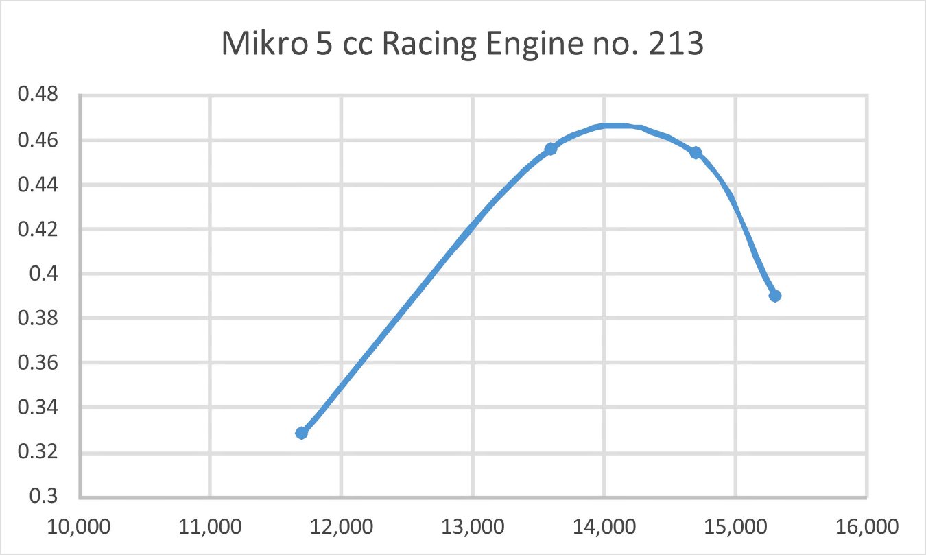
I restricted the initial runs to five minutes each, allowing complete cooling between runs. After some fifteen minutes of running, the rings had begun to bed in quite well, creating an ever-improving seal. In addition, the engine displayed no tendency to nip up or sag when briefly leaned out from time to time. Even so, I put on a total of 45 minutes before deciding that the Mikro was ready for testing to begin. Once I judged that the engine was ready for testing, I switched to a fuel containing 30% nitro for the actual test. Given the hotter fuel plus the fact that I would be leaning the engine out for more extended periods, I fitted a colder plug for this phase. For each tested prop, I began with the engine completely cooled down. The engine was started and allowed to warm up slightly rich for at least one minute, after which it was briefly leaned out by pinching the fuel line to get the maxuimum speed reading and was then richened once more by releasing the pinch in the fuel line before being stopped to cool down and change props. The advantage of using the fuel line pinching approach to going for the maximum lean setting is that it allows the tester to react instantly to any sign of distress by simply releasing the pinch, thus immediately restoring a rich mixture. With a more-or-less new engine, it can be a very valuable precaution. In the present instance, however, no such issues were encountered. Using the 30% nitro fuel, the following figures were obtained:
It must be noted that the props represented in the above data are not part of my well-used and reliably calibrated test set. There is thus no reason to assume that the same power absorption coefficients necessarily apply, although they should be close. This being the case, the BHP figures shown here must be regarded as approximate only. Still, they're doubtless close enough for present purposes. Obviously one cannot generate a truly representative power curve from only four data points. The curve presented above is therefiore only an approximation at best. It does however appear certain that the engine had passed its peak on the 8x4 and that maximum power was developed at a speed somewhere between the figures measured for the middle two props. We probably wouldn't be too far off the mark to suggest an implied peak output of around 0.465 BHP @ 14,200 rpm. This may appear to be a less than stellar performance for a 5 cc racing engine, but we must remember that this was 1951! The contemporary ETA 29 Mk. II developed a factory-claimed output of over 0.610 BHP @ 15,500 rpm, a figure which was confirmed by Peter Chinn in his later test of the ETA 29 Mk. III which appeared in the May 1954 issue of “Model Aircraft”. Admittedly, in standard trim the Mikro seems to have fallen somewhat short of matching this figure, but an experienced eye can readily detect a number of easily-applied modifications which would raise the performance of the standard Mikro considerably. In particular, delaying the very early closure of the disc valve by some 25 degrees or so and perhaps having it open a trifle earlier would unquestionably improve the engine's top-end, raising its peaking speed substantially. The optimization of the shape and registry precision of the piston skirt ports and their cylinder wall counterparts also offers considerable scope for improvement. Naturally, I have no intention of modifying this pristine original example of the engine in any way. To do so would be both completely pointless and highly irresponsible in conservation terms. However, I objectively consider it possible that the performance of the Mikro could readily be brought up to a level closely approximating that of the contemporary ETA design, making it a very competitive engine by the standards of its day. Marketing History The Mikro 5 cc racing engine appeared on the Danish market in 1951 at a price of 150 kroner (approximately US$22.00 at the time). It was initially greeted with enthusiasm by the Danish modelling fraternity, particularly those who were involved in tether car racing. However, this enthusiasm was quickly tempered by the publication of a test which reported an output of only 0.350 BHP @ 16,000 RPM. This of course was not in the least competitive with the outputs being reported for competing products such as the Dooling 29 and ETA 29. It also fell very far short of the figure which I myself measured for my example of the engine, albeit at a higher speed. Despite this, the engine actually gave a good account of itself, winning many competitions. This was very likely the result of careful tuning by knowledgeable owners – as stated earlier, a number of easily-applied modifications which would undoubtedly enhance performance are readily apparent to an experienced eye. Kai Nielsen later recalled that a number of examples were exported to the USA, where they competed against various American products.
Speaking years later to Jens Geschwendtner, Nielsen recalled that perhaps 500 examples of the engine ended up being manufactured in total. Many of these remained unsold for many years – as late as 1984, new examples could still be purchased from the manufacturer’s New Old Stock at a bargain price of 50 kroner (approximately US$6.70)! One can only dream ..........I suspect that my own previously unused example is one of these units. The failure of the Mikro 5 cc racing engine in the marketplace was the final straw for Kai Nielsen, who abandoned the model engine manufacturing field for good at the end of 1951. His company continued in operation, however, still being in business as of the mid 1980’s and working on a variety of special projects. The latter-day address of the company was Thoravej 23, 2400 Copenhagen N. Conclusion I hope that you’ve enjoyed this in-depth look at one of the often-overlooked model racing engines from the “classic” era. The Mikro 5 cc racing engine was a well-executed and quite original product from a highly competent manufacturer. It may not have been a world-beater as delivered, but it did have considerable potential. In my personal book, it did Denmark proud! This is an engine that deserves a respected place among the 5 cc racing units of the “classic” era! ______________________________ Article © Adrian C. Duncan, Coquitlam, BC, Canada First published January 2018
|
||
 Model engine manufacturers from many countries have found the siren call of high performance difficult to resist. A few manufacturers such as
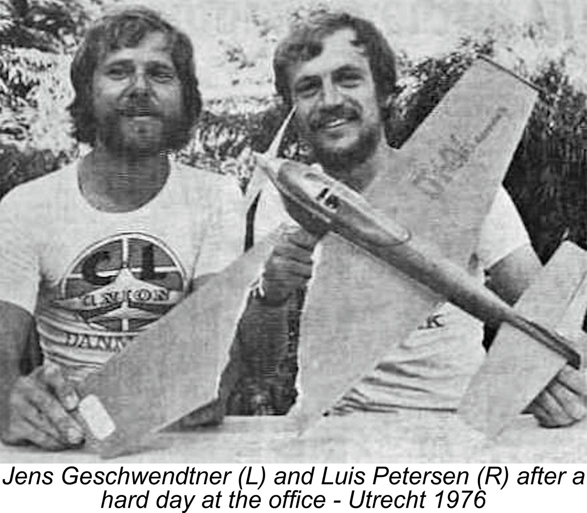
 The workshop which manufactured the Mikro model engines was established by Kai Nielsen in February 1937 as the “Kai Nielsen Mechanical Workshop”'. The business was located at Kronprinsensgade 8, Copenhagen. The start was quite modest, since Nielsen had only a single turret lathe at the outset. During the early years, the workshop functioned primarily as a photographic equipment repair shop. It appears to have been relatively successful, soon growing to the point where additional staff were employed.
 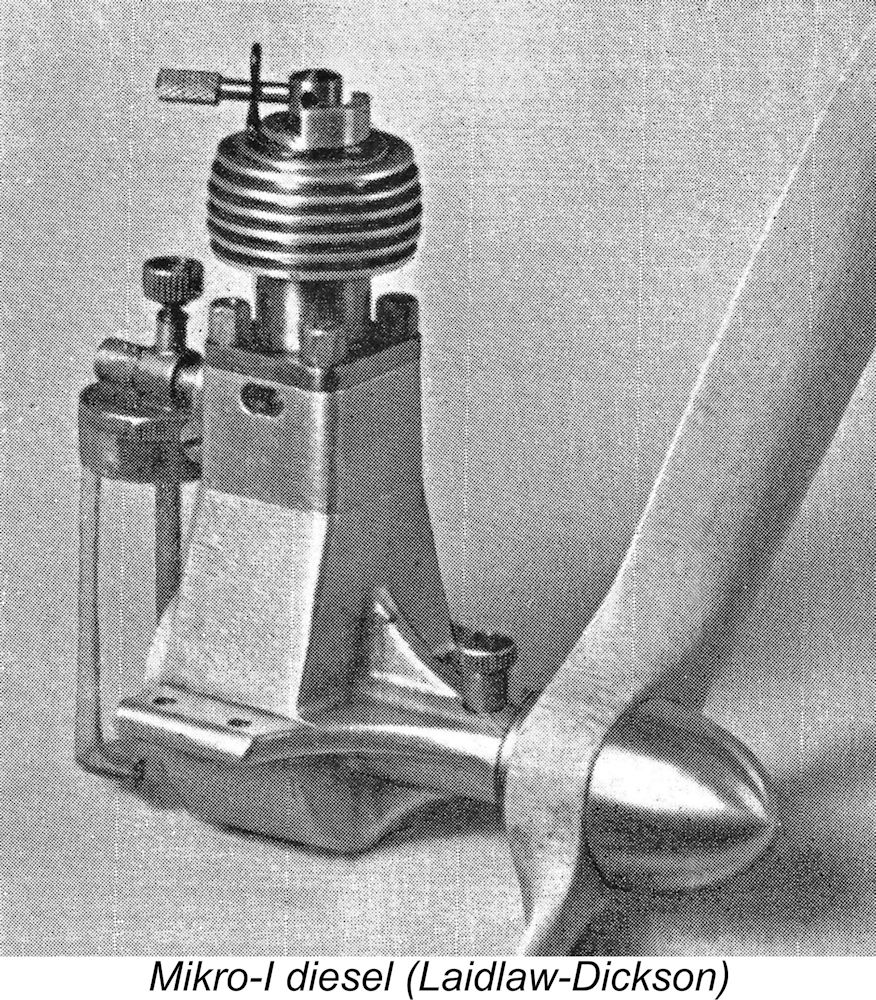 At the outset, Kai Nielsen had heard that many other then-available model diesel engines could be a bit of a challenge to start. It's likely that this was primarily due to inexperience with model diesel engines on the part of many contemporary modellers, for whom this was a new technology. However, Nielsen evidently attributed much of this to variations in the piston/cylinder fits of these engines. He therefore specified very fine tolerances for the fit of each piston in its individual cylinder.
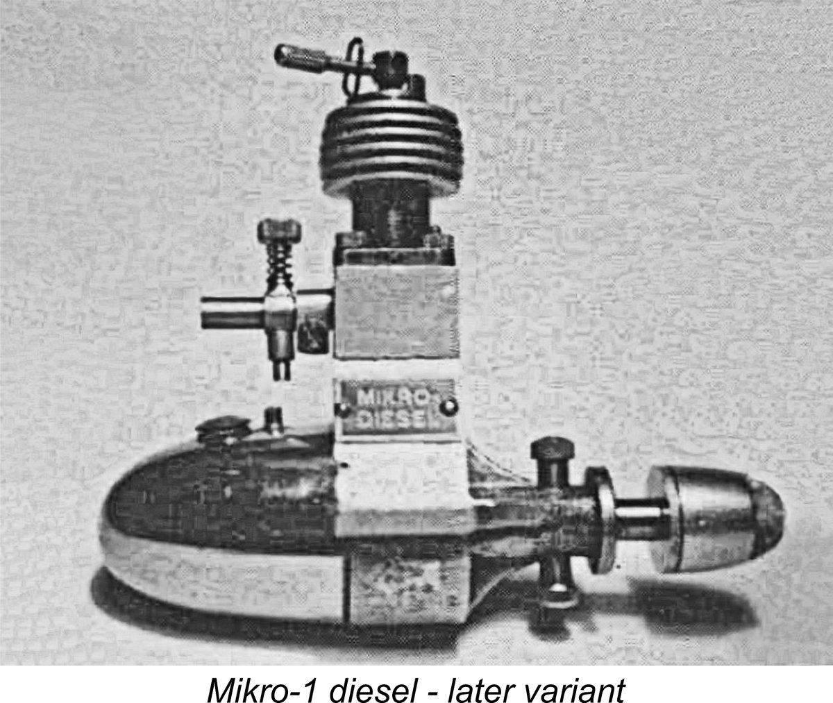
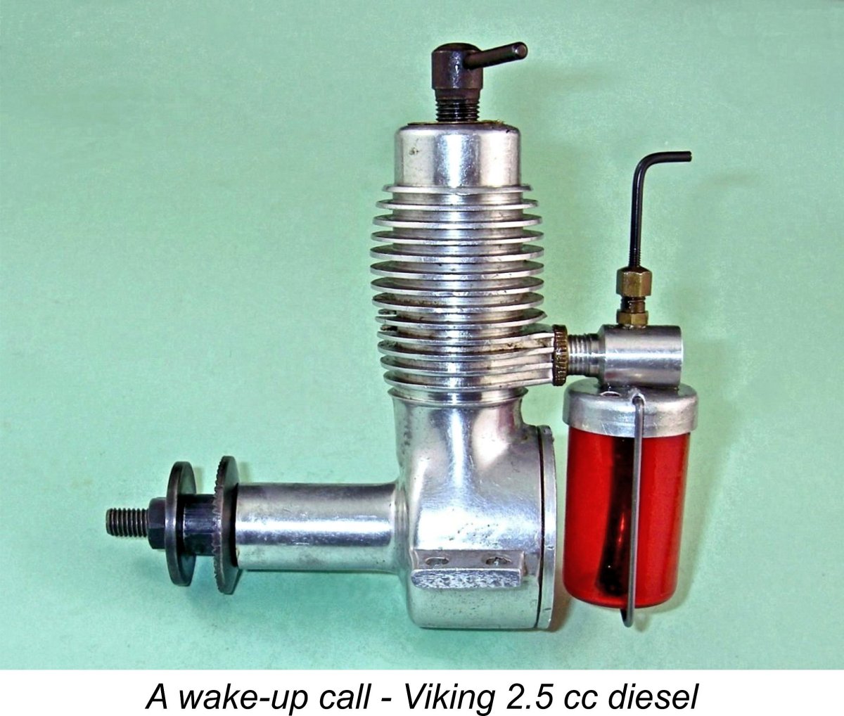 The demand for engines in the 2 cc displacement category continued unabated, eventually leading Nielsen to take a fresh look at his increasingly venerable sideport design which in effect dated back to 1941 in terms of its Dyno genesis. As the nineteen-forties drew towards their close, rumours began to circulate of a new 2.5 cc model being developed by Christian Tommerup Clausen of Lundbyvej in the northern part of the south-central Danish island of Fyn, on which the city of Odense is located. This engine was destined to appear on the Danish market in early 1950 as the Viking 2.5 cc diesel, becoming an immediate success. I’ve covered the story of the
 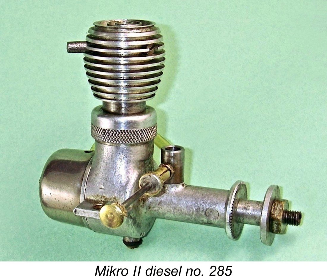 However, the Mikro-II was evidently released prematurely before all of the bugs had been worked out. It quickly became apparent that there were many problems with the original version of this model. The cylinder was made too thin, consequently tending to split. The contra-piston was somewhat awkwardly adjusted by rotating the entire cooling jacket by means of a tommy bar which was inserted into one of a number of holes drilled radially in the cooling fins around the jacket’s circumference. In addition, the motor was provided with only two holes for mounting, a detail that probably stemmed from the engine’s primary anticipated use in model race cars. The fact that the engine was timed for reverse rotation was also a symptom of this expectation.
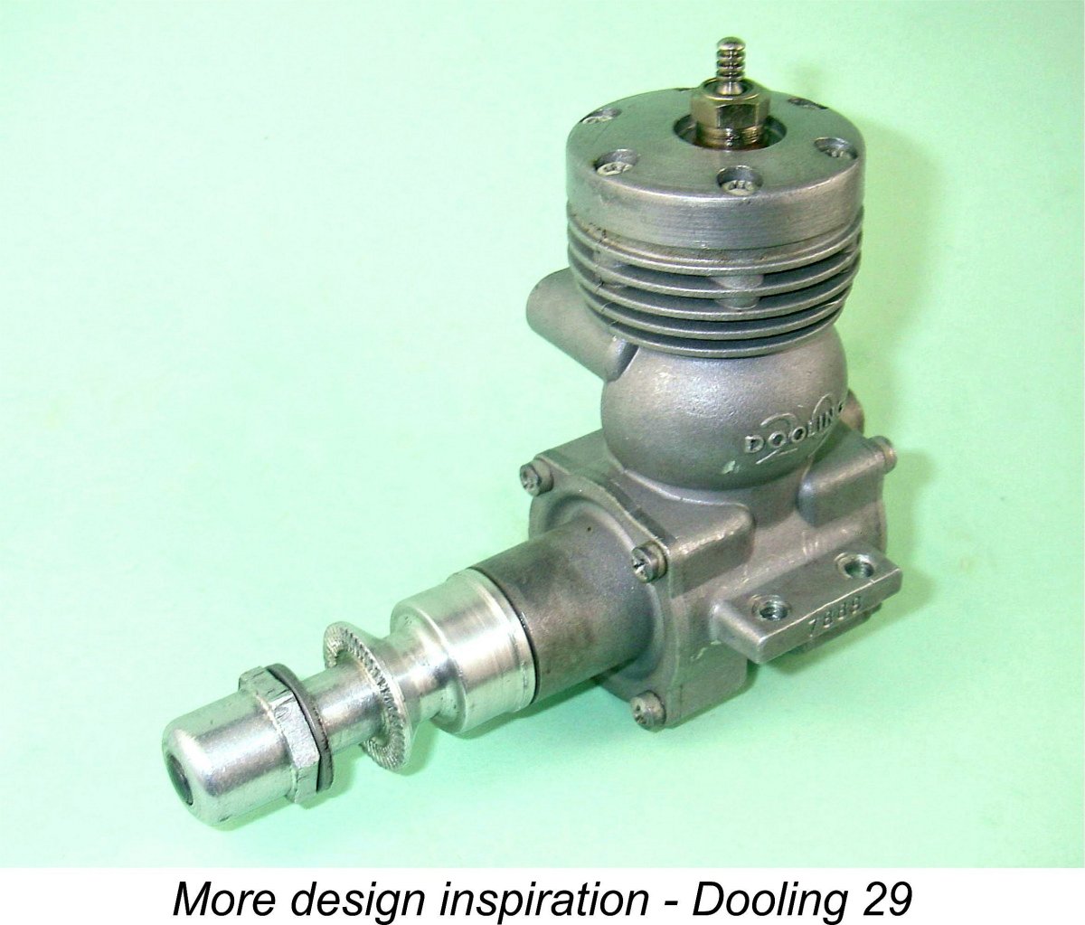
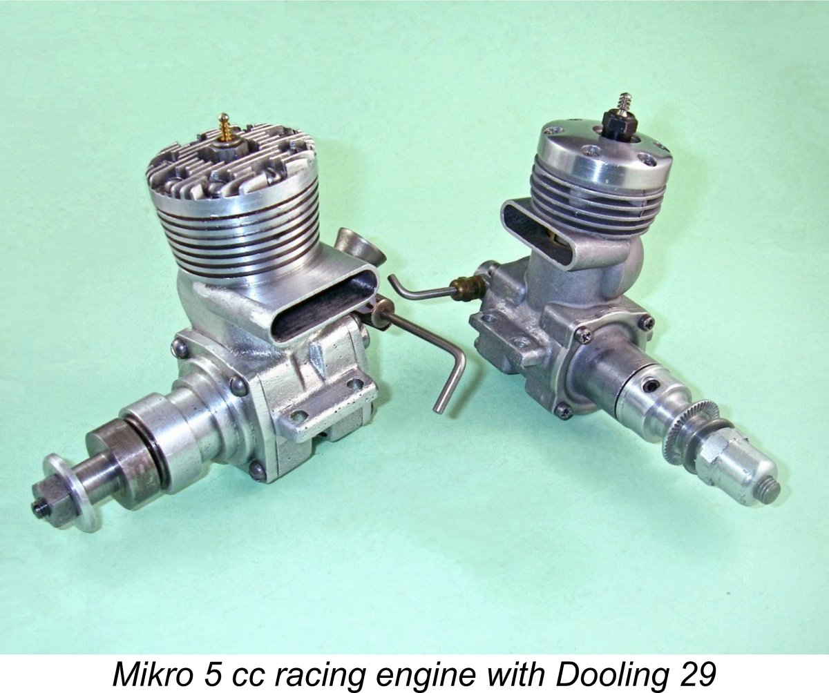 Although there’s no doubt at all that the design of the Mikro 5 cc model was influenced by that of the Dooling 29, the two engines present very different external appearances. Even internally, the differences are far more marked than we might suppose. In no way can the Mikro legitimately be characterized as a copy or “clone” of the Dooling. It is every bit as much an original design as any of its contemporaries.
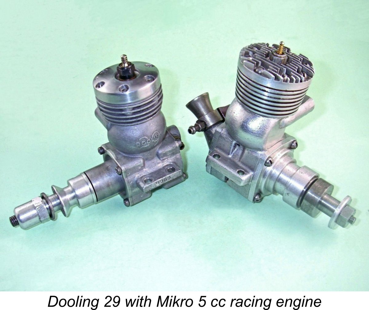 Another similarity is to be observed in the bypass arrangements of the two engines. Like the Dooling, the Mikro employed a bypass bulge which had no direct communication with the crankcase. Gas passage from the crankcase into the bypass was provided for by the presence of three apertures cast into the piston skirt. The central aperture was oval in shape, while the two outer apertures took the form of elongated slots. They registered at bottom dead centre with matching openings cut through the cylinder wall. This configuration had the advantages of minimizing both crankcase volume and piston weight as well as improving piston cooling.
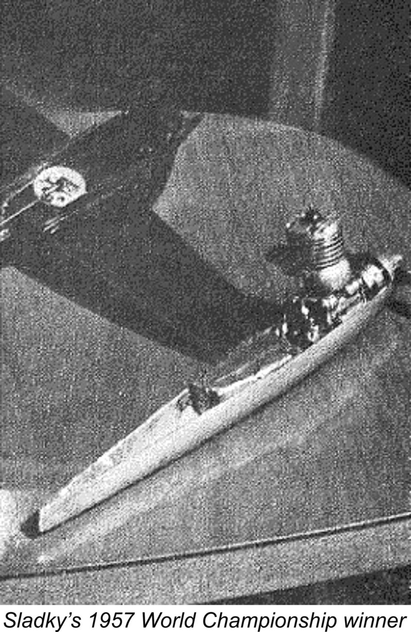
 Having dealt at length with the Mikro’s Dooling-derived features, we now turn to the differences, of which there were many. The first major clue that things are very different comes from a comparison of the respective bulk and weights of the two engines. The Dooling weighed in at a quite reasonable 194 gm (6.84 ounces), but the far bulkier Mikro tipped the scale at a whopping (for a 5 cc unit) 320 gm (11.29 ounces). Quite a difference!! Many 10 cc engines don’t weigh any more than that………………
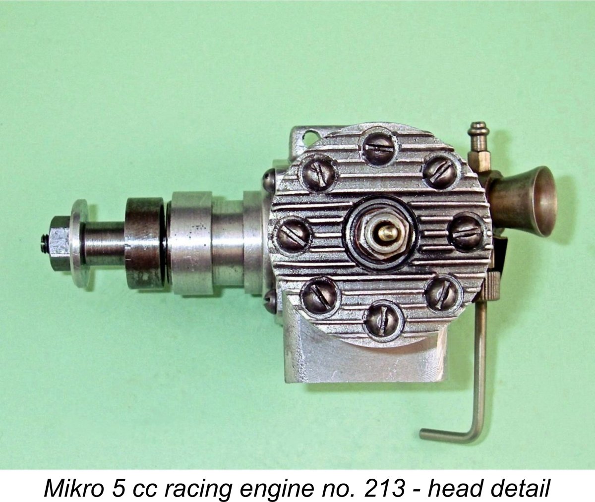
 The cylinder liner is of heat-treated steel. Both exhaust and transfer ports are generously proportioned and are bridged to retain the two rings with which the piston is fitted. The lower cylinder on the transfer side is provided with three apertures which correspond to those in the piston skirt at bottom dead centre. The piston itself is another aluminium alloy sand-casting having a high domed deflector crown. The underside of the cylinder head is contoured to match. Volumetrically-checked geometric compression ratio is 8:1.
 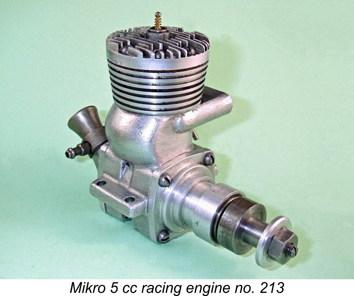 At the front, we find another contribution to the engine’s high weight – the very substantial prop driver is machined from steel rather than the more usual light alloy. Somewhat unusually, the driving face of this component is not provided with any form of knurling or serrations to limit prop slippage.
 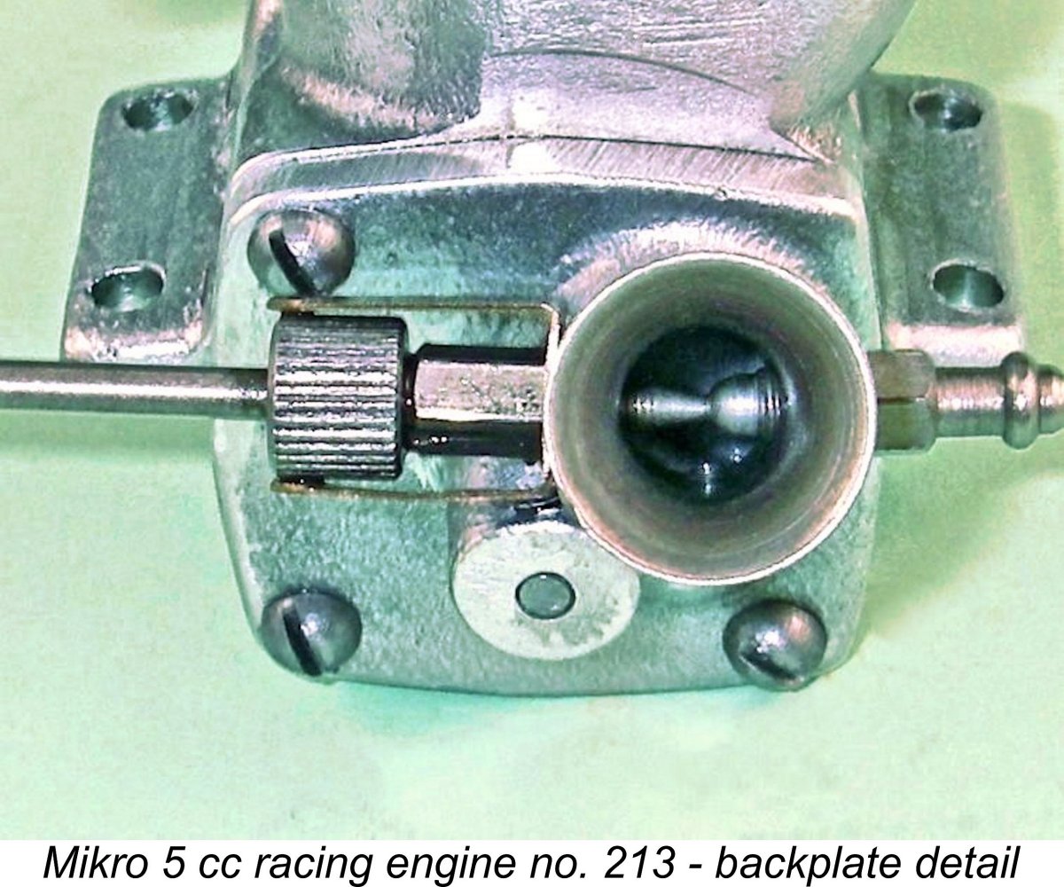 The designer’s lack of concern with weight reduction is confirmed by the fact that the entire carburetor assembly (venturi, jet, needle carrier and needle) is made of steel. It’s very clear that the achievement of minimal weight was not a high priority for this engine’s designer! This of course is once again consistent with the idea that this engine was intended primarily for tether car racing.
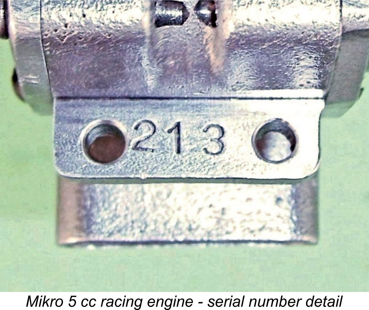
 The engine's highly inconvenient prop hub diameter of 10 mm posed a problem for me due to the fact that my standard calibrated test props are all bored out to 0.375 in. (9.52 mm) - I use sleeves to accommodate smaller hub diameters. I could have turned the Mikro's hub down to the required diameter, but I was reluctant to disturb the originality of this fine example of the engine. Instead, I scrounged among my vast and rather disorganized prop collection, eventually coming up with a somewhat small but perhaps adequate suite of suitable test props which had been previously bored out to 10 mm in connection with their use on other similarly-challenged engines.
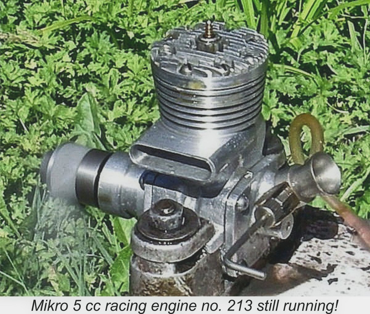
 For one reason or another, overall sales were not encouraging. In large part, this was doubtless due to the engine’s unsuitability for aircraft service due to its very high weight and considerable bulk. The immediate demand from Danish tether car racers would have been satisfied fairly quickly, after which further sales would have to come from the model flying fraternity, for whose purposes the engine was less than ideal. In addition, the previously-mentioned lukewarm test report doubtless added its own contribution to the sales resistance which the engine clearly encountered. Finally, Nielsen found that he could not compete in price terms with the higher-production engines from other countries.
| |