
|
|
Norway’s Finest - the David-Andersen Engines
However, one of those producers stands very high in the rankings of model diesel engine manufacturers of the 1950’s and 1960’s. This is true both in terms of design innovation and quality of construction. We are speaking of the range of model diesel engines produced in Olso, Norway between 1950 and 1964 by Jan David-Andersen, one of the true pioneers of model diesel engine design. When writing about the activities of a manufacturer in a non-English speaking country, it’s usually extremely difficult to obtain authoritative first-hand information from within the country in question. Normally in such cases one has to rely upon commentary in the English-language modelling media. As far as the basic facts surrounding the David-Andersen engines go, this is not much of a problem since the engines were quite well covered in British and American modelling periodicals. Consequently, a fair amount of source material is to be found in the contemporary English-language modelling press. Perhaps the most important such media resource is the article on David-Andersen engines by Bob Leisses which appeared in issue 62 of the invaluable but sadly now-discontinued “Engine Collector’s Journal” (ECJ) for March/June 1977. Bob was a personal friend of Jan David-Andersen, spending several holidays in Norway with the David-Andersen family and some of Jan’s modeling friends. The coverage in the article was not complete, necessarily so since the story was by no means over at that time. However, it did include a great deal of relevant information, all of which had apparently been confirmed by Jan based on his proof-reading of the text prior to publication. My sincere thanks are due to my valued friend and colleague Tim Dannels, the former publisher and Editor of ECJ, for bringing this article to my attention. In addition, we are indeed fortunate in that a Norwegian facility called (in English) the Bodø Aviation Museum has very commendably elected to include a number of Norwegian model aero engines in its most interesting collection. When this article was written in 2014, the website of this facility included a page on Norwegian model engines which was assembled by Gunnar Kock. Most importantly for our purposes, this page was provided with an English translation. Unfortunately, it appears to have gone offline since the original article was written, but not before I was able to extract some very useful information along with a few photographs. The page included a number of illustrations of the collection of David-Andersen engines which is on display at the Norwegian Aviation Museum in Bodø. These images were taken by Gunnar Kock. I freely acknowledge having drawn upon the material that was to be found on this most interesting site. My very sincere thanks are hereby extended both to Gunnar Kock and to the Society for making this valuable information so readily accessible. It was this resource that really got me started on this project.
Even more importantly, Åsmund was able to put me in direct contact with Jan David-Andersen’s son Bjørn. I thus received confirmation that at my original time of writing (late 2014) Jan David-Andersen was still going strong at age 93 and still designing and building model engines!! A video clip sent by Bjørn showed Jan hand-starting his latest creation – a 2.8 cc diesel which apparently developed over 0.30 BHP @ 12,000 rpm in its brand-new state. This engine was designated the Drabant 2013 to reflect the year of its design.
Jan never became a computer user, hence being unable to correspond with me directly by email. However, Bjørn was good enough to share some of his reminiscences about his father’s activities for inclusion in this article as well as kindly reading the article to correct any errors or omissions. It would be impossible to overstate my debt to Bjørn for his invaluable co-operation. As if this wasn’t enough, Jan himself went so far as to do me the honor of reading this article in its near-complete form. He was kind enough to praise it very highly, stating that both he and his wife were extremely happy with it. He was able to add a few details which had escaped me, understandably so since Jan was the only one who retained any knowledge of them! As a result, this may well prove to be the definitive English-language article on the history of the David-Andersen engines. We are all greatly in Jan’s debt. At this point, my good friend Tim Dannels stepped in once more to place me even deeper in his debt by allowing me direct access to another invaluable piece of the overall picture. Many years ago now, Tim had direct contact with Jan David-Andersen, who was kind enough to present Tim with a copy of his ground-breaking 1945 Norwegian-language book on model diesels, of which more below in its place. It was my privilege to be entrusted by Tim with his author-autographed copy of this rare pioneering work for the purpose of scanning it and translating it into English. With the much-appreciated assistance of Lars Gustafsson and Bjørn David-Andersen, this was duly accomplished, providing us with an invaluable record in Jan David-Andersen’s own words of his approach to model diesel engine construction during the pioneering era. The English translation of this work will be found elsewhere on this web-site, complete with a signed preface contributed by Jan himself. Tim was also good enough to send me a copy of the previously-mentioned Spring 2014 issue of the Norwegian old-time modelling periodical “Old Timer Modeller I Norge”, in which the plans for Jan’s most recent model engine design were published. Jan continued to machine all the parts himself using the same original equipment with which he started apart from a later self-designed combined drilling and milling machine. A true inspiration to all of us! Having acknowledged our sources, let’s now see what we can do to present a coherent summary of the events leading up to Jan David-Andersen’s entry into the model engine manufacturing field as well some details of the fine series of model engines which resulted from his activities. The Early Years
Jan David-Andersen did not commence the series production of model engines on a commercial basis until 1950, when he was 28 years old. However, his involvement with model diesel engines went back for many years prior to his entry into the commercial manufacturing field. In a very real sense, he must be regarded as one of the true pioneers of model diesel engine technology. During the period when Jan David-Andersen first became involved with model engine design, one of the employees in his father’s jewelry workshop was a man named Schumann, who among other things was a skilled toolmaker. Schumann reportedly became a kind of mentor to young Jan, providing him with both an interest in machinery and a practical grounding in precision engineering from a relatively early age. The Hamilton lathe in his father's workshop was Jan’s main item of equipment during the early years of his involvement with model engines, although it was of course only available for his use when not needed for work in support of his father’s business. J The largest model flying club in Norway was the Oslo Modellfly Klubb (Oslo Model Flying Club) which at one point during the post-war period boasted well over 300 members. This club had been formed during the pre-war period, along with a number of others at various locations. As a youth, Jan David-Andersen was a member of the Oslo Modellfly Klubb, although in 1941 at the age of 20 he joined with a dozen or so friends in starting a separate club called the Vingtor Modellfly Klubb (Vingtor Model Flying Club).
Thus began a five-year period of armed occupation which was only ended by the conclusion of the war in Europe on May 8th, 1945. Both the Norwegian Royal Family and the members of its elected Parliament were evacuated along with the National Treasury only a few hours before the Germans sized control of Oslo. As a result, Norway never formally surrendered to the Germans since everyone with the authority to do so had left the country. Norway thus never became a conquered nation. Its elected government remained in being, albeit in exile, thus confirming the legal illegitimacy of the Quisling puppet government. This allowed the country's free forces to participate as active allies alongside Britain and others throughout the war, compiling a proud record of service in so doing. During this unhappy period, the ongoing operation of the model engines already in the country was understandably rendered very difficult. The Oslo Model Flying Club was officially disbanded by the Nazis, along with other similar groups. It’s a tribute to the enthusiasm of the Norwegian model flying community that this official sanction against the hobby did absolutely nothing to deter its members from continuing to follow their passion. On the contrary, Jan and his friends promptly founded the previously-mentioned Vingtor Model Flying Club in defiance of the Nazi ban. Under the auspices of this and other similar groups, model flying continued, albeit at a rather lower profile than before. In effect, the modelling community simply went underground, continuing to hold clandestine model flying meets throughout the war, often under the very noses of the occupying power. The human spirit is very difficult to suppress! It's very difficult to believe that the Germans could have remained completely unaware of this supposedly illicit activity. The fact that they evidently did little or nothing to stop it would appear to indicate that despite the official ban, the Germans in reality saw little harm in allowing the Norweigians to engage in recreational activities of this kind. Perhaps they reasoned that the forcible suppression of such outlets would inevitably lead to the development of sullen resentment, which could evolve into active resistance. There was enough of that from the Norwegian Hjemmefronten (Home Front) movement without any further encouragement. This view of the probable German "blind eye" attitude is supported by a wartime incident which Jan recalled for us. During a supposedly-illicit flying session, his free-flight model took an unplanned overland course which resulted in its ending up landing in a German barrack compound! This alone supports the "blind eye" theory, since the flying session was obviously taking place in close proximity to a concentration of German occupying troops, some of whom could scarcely have failed to notice it. Doubtless in some trepidation, Jan summoned up the courage to present himself at the compound gate the next day to ask for his model back! He was shown into one of the barrack blocks, in which his model was hanging from the ceiling, still smelling strongly of petrol! Not only were the Germans perfectly friendly, but they actually displayed considerable interest in the model and its operation. After explaining a number of details, including the fuel used, Jan got his model back and was allowed to walk out unhindered. Whew!! The wartime situation obviously precluded any possibility of obtaining additional model engines from outside the country. This inevitably led enthusiasts like Jan who had both an interest in the subject and some mechanical ability to investigate the possibility of making their own engines. The then 19-year old Jan threw himself into this line of investigation with great enthusiasm, the result being the 1941 appearance of the first-ever David-Andersen model engine, a one-off 3 cc spark ignition model which Jan later recalled as being “something like a big Ohlsson”. Unfortunately, Jan was never able to get this engine to run for him. He ended up selling it to a friend of his who did get it running, perhaps because he had access to better spark plugs. So that first David-Andersen design was ultimately a success, albeit not for Jan! During the ensuing war years, Jan managed to make a number of individually-produced 3.5 and 4 cc spark ignition engines for the clandestine use of himself and a few friends. However, his very limited access to machine tooling at the time meant that he was unable to even contemplate the commercial production of such engines even if market conditions had been more favourable than they were during the war years. Prior to 1943, all of Jan’s efforts had been focused upon the spark ignition engines which were all that he was aware of at the time. However, over in neutral Switzerland events had been unfolding which were ultimately to re-shape the course of Jan’s involvement with model engines.
Some ten years later, Thalheim went into production with a series of engines which were marketed from 1938 onwards under the ETHA label, derived of course from Thalheim’s name rather than from a primary ingredient of the engine’s fuel! These appear to have been the world’s first commercially-produced model diesel engines. It’s a bit of a mystery why it took Thalheim ten years to actually begin to capitalize upon his patent ….. most likely the world-wide Great Depression which was triggered by the October 29th, 1929 crash of the New York Stock Exchange had a lot to do with this. The ETHA engines were large, heavy and cumbersome. However, they were reportedly very competently constructed and ran well, thus proving the concept for all to see. They were sold through a shop located on the now-exclusive Bahnhoffstrasse in Zurich which was then owned by a certain Herr Feucht. We are greatly indebted to prominent English collector Peter Scott, a former resident of Switzerland, for this information. Maris Dislers' review and test of the replica ETHA 1 diesel made by Richard Gron may be found elsewhere on this website. The technological success of the ETHA engines naturally inspired others to have a go for themselves. The Dyno 2 cc model manufactured in Switzerland by Klemenz-Schenk was one of the earliest spin-off products, being developed in 1940 and making its market debut in 1941. It was a considerable step forward from the Despite the fact that by the early 1940’s most of Europe was heavily embroiled in WW2, word about this then-innovative type of model engine somehow trickled out of Switzerland to reach a number of other European countries, both neutral and occupied. In an article which may still be found here on the late Ron Chernich’s wonderful “Model Engine News” (MEN) web-site, we have recorded the amazing and inspiring history of wartime efforts in German-occupied Czechoslovakia (now the Czech Republic) to develop model diesel engines under very difficult circumstances. News of the new technology also reached neutral Sweden in 1942, along with an actual example of the Dyno 2 cc engine which somehow crossed war-torn Europe to come into the possession of Gunnar Fahlnäs, then the editor of the popular Swedish technical magazine “Teknik för Alla”. Impressed with the performance of the Dyno, Fahlnäs commissioned Swedish model engineering pioneer Ivan Rogstadius to develop a Dyno-based design for home construction, using his original Dyno as the prototype. Plans were drawn up during the Despite the fact that Norway was under German occupation at this time, some information regarding model engine developments in other countries became sporadically available to Norwegian enthusiasts from German, Swedish and Swiss sources. Although the exact details are now sketchy, it appears that Jan David-Andersen first became aware of the model diesel engine principle in 1943, most probably from his reading of the 1943 articles in “Teknik för Alla”, which remained in publication throughout the war. As a result, Jan became aware of the new technology very early on. The fact that model-scale spark plugs and batteries were extremely scarce in Norway both during and immediately after the war greatly enhanced the attraction of the compression ignition engine. In addition, the extreme cold typically encountered during the winter flying season had a most detrimental effect upon battery performance, which the diesel neatly sidestepped. Seeing the obvious advantages of being able to dispense with the parasitic and temperamental electric ignition support system in favor of a dependable all-weather set-up, Jan immediately began to draw up his own design for such an engine.
Jan continued his design and development work, eventually coming up with a workable design for a 3.5 cc model diesel engine. A prototype of this design was made during the winter of 1943/44. Jan was kind enough to share his recollections of the initial test of this engine with Bob Leisses. He was of course breaking new ground with this model, having no previous operating experience upon which to draw. Consequently, compression settings for the initial start were nothing more than a guess! Having mounted the engine with its propeller fitted and arranged a supply of suitable fuel, Jan took on the task of flipping the propeller while a good friend of his, fellow Vingtor member Sigurd Heiret, operated the "kompressjonsskruen" (as the comp screw is termed in Norwegian). After some fiddling and flicking, the thing finally fired for the first time…………..and Sigurd felt it "explode" under his hand! It turned out that the main casting had been flawed. As a result, the casting failed on the first firing stroke, leaving Sigurd standing there with the top of an engine in his hand! Oops ……!! Part of the problem here may have been the fuel that Jan was using. In his previously-mentioned 1945 book (of which more below in its place), Jan recommended a fuel mixture consisting of 2 parts white spirit (paraffin), I part naphtha and 1 part SAE 70 oil. It would appear that diethyl ether was not available in wartime Norway! The problem with this fuel would have been that the auto-ignition temperature of naphtha (the temperature at which it ignites spontaneously without an ignition source) is 225 degrees Celcius, significantly higher than the 160 degrees Celcius of diethyl ether and actually more or less identical to the comparable figure of 220 degrees Celcius for refined kerosene (paraffin). Wartime paraffin may have had an even higher auto-ignition temperature. Regardless, the compression ratio needed to start a model diesel using a naphtha-based fuel would have been considerably higher than with an ether-based fuel. That said, Jan had no choice other than to use what was available ……..
According to Bjørn David-Andersen, Sigurd later crashed the Fly Baby, fortunately without doing himself any permanent damage! Apparently, he never flew it again - Bjørn has no knowledge of its final disposition. Returning now to the less-than-positive results of the initial test of Jan David-Andersen's first self-constructed model diesel, Jan was certainly not the man to let the matter rest there! A number of refinements were quickly developed by trial and error, beginning with the production of some sound castings. A revised prototype was soon being successfully tested, impressing Jan and his friends to the point that a run of ten examples of this 3.5 cc model was produced by Jan in 1944. The very small number of engines produced does not alter the fact that this was the first-ever production run of model engines produced by Jan David-Andersen.
It’s worth mentioning at this point that Jan was not the sole Norwegian engaged in the design and construction of model diesel engines at this time. While Jan was pursuing the activities previously described, an individual named Øivind Andersen (not a relative) was following a parallel design and construction path. Øivind was a clever machinist with an inventive mind – not unlike Jan David-Andersen, in fact! In 1944 he finalized his own design for a model diesel engine, actually going so far as to produce about 150 examples of his design, albeit on a part-time basis as other commitments permitted. Øivind thus became the first individual in Norway to engage in the series production of model engines on anything approachng a commercial scale. Øivind’s design displayed a good deal of original thinking. However, the engines were not a commercial success, most likely because of the negative influence of the ongoing Nazi occupation upon the Norwegian model market. The venture was soon abandoned. This by no means put an end to Øivind’s model engine design and construction activities. As an active member of the Olso Model Flying Club, which re-formed immediately after the end of the war, his enthusiasm for model diesels had stimulated considerable interest among his fellow club members, encouraging him to continue to produce small numbers of custom-built model diesels in displacements ranging from 0.25 cc up to 4.5 cc for his own use and that of a few of his fellow club members. As of mid-1950 Øivind was still working on a variety of innovative model diesel designs, including one with a disc valve having variable timing (shades of the 1946 Atomic 60 from America) and a model having three bypass ports with a single exhaust port, one of the bypass ports being directly beneath the exhaust port. This actually sounds as if it might have been an early attempt at Schnuerle porting! This latter engine used a multi-petal reed valve on the backplate, looking much like a Dynajet valve. With all of this creative ingenuity on tap, it seems a pity that Øivind never resumed the series production of model engines. Given the fact that Jan David-Andersen lived in Oslo both during the war years and from the latter part of the 1940’s onwards, (see below), it appears inconceivable that he would not have had some level of contact with Øivind together with opportunities to exchange ideas on model diesel design. However, Jan evidently maintained a low profile – in an article which appeared in the July 1950 issue of “Model Aircraft” under the title “Aeromodelling in Norway”, author R. W. Smyth did not so much as mention Jan David-Andersen’s name, although Øivind Andersen’s model engine construction activities were covered in some detail. As of 1977 when Bob Leisses was writing, Øivind was still active, operating a machine shop making parts and tooling for Scandinavian Airlines System (SAS). Seeking to clarify some design details of Øivind’s 1944 model diesel design, Jan David-Andersen called Øivind in February 1977. As a result of this contact, Jan was made aware of the method used by Øivind for compression ratio adjustment in that pioneering model. This system is both highly ingenious and unique in my personal experience. As such, it merits a full description here.
Internal channels almost like splines acted as bypass passages which supplied an annular transfer port machined around the entire internal circumference of the cylinder bore. The porting was basically the same as that developed independently in the USA by Ray Arden at approximately the same time. This bypass arrangement was later to re-appear in the 1948 K Vulture 5 cc diesel from England. It should be obvious that unless the internal bypass flutes were interrupted at some point by a plain section of the bore, side-port induction could not have been employed. Unfortunately, Jan did not report on the issue of the engine’s induction system. I am presently unaware of any surviving examples of this fascinating design. An opportunity to examine one or even test it would be of the greatest interest! Thanks are due to Jan David-Andersen for his key role in preserving this information.
The design of this engine’s contra-piston constituted an excellent example of Jan David-Andersen’s ability to think “outside the box”. Most unusually, the contra-piston took the form of a blind-bored cap on top of the cylinder, the sealing area being on the outside of the outer cylinder wall! Moreover, it was made up of two components – an aluminium alloy blind-bored cap which sealed the bore and a steel outer ring which encircled the exterior of the cap. The outer circumference of the cap was given a 1 degree taper which matched a similar taper on the inside surface of the ring. The cap was fitted onto the cylinder, after which the ring was pressed down on it, thus compressing it thanks to the wedging action of the taper. This was continued until the correct combination of gas seal and setting-retention friction was established. If leakage or looseness developed, all that was required was to press the ring down a little further to compress the cap a little more. Ingenious! A steel plate on top of the cap prevented the comp screw from gouging into the aluminium cap.
Unfortunately, the book included neither a summary of Jan’s earlier experiences with model diesels nor his impressions of other designs. Instead, it summarized the personal approach to model diesel construction and operation which he had evolved during his two years of constructing such engines as a hobby. Much of the advice on model diesel construction which appears in the book remains just as valid today as it was when the book was written. Given the fact that model engines were not commercially available in Norway during WW2 or for some time thereafter, this book must have been a very useful guide to those wishing to construct their own engines. Following the writing of this book, a further run of ten engines was produced. These dispensed with the contra-piston, instead featuring an eccentric crankshaft bushing. By rotating the bushing using a suitable handle, the vertical distance between the central crankshaft axis and the cylinder head could be varied, thus also varying the clearance between the piston and the upper termination of the blind-bored cylinder at top dead centre. This in turn changed the compression ratio. As with Øivind Andersen’s unique diesel, the purpose was to create a shorter engine, since no comp screw was required. These engines were all 3-port (side-port) designs. Although he was later to apply the eccentric bearing system to his first series production model (of which more below), Jan eventually came to feel that it was not a good idea. For one thing, cylinder port timing was affected by the displacement of the piston travel path. For another, the system was not practicable for anything other than a side-port or reed valve engine. In addition, the design precluded a good "running in" of the main wearing surfaces given that the orientation of the main bearing relative to the loading was always changing, as were the limits of the path travelled by the piston in the bore. Hence such engines never really had a chance to "settle down". Following the end of the European phase of WW2 in May 1945, Jan took a two-year step back from his intense involvement with model engines – he had a living to earn! During this period, he completed his technical education at the prestigious Royal Institute of Technology in Stockholm, Sweden. He then married his wife Ann-Grethe (to whom he remained happily married at the original time of writing in late 2014!), after which he relocated temporarily to England, where he worked at the Rover automobile factory in Coventry to gain practical experience in production engineering.
One item which was provided to Norway under the Marshall Plan was a South Bend lathe which ended up in Oslo in 1948. It was slated to be loaded onto a ship to be transferred to a different location elsewhere but was somehow delayed in transit, missing the ship as a result and ending up as an orphan on the Oslo dock. Naturally, such an asset could not be allowed to go to waste, the result being that the orphaned lathe soon found a good home in the basement of Jan David-Andersen's parents' house, where it became the focal point of Jan’s fledgling machine shop. As of 1977, when Bob Leisses was writing, that lathe remained a treasured feature of the David-Anderson factory, albeit having been joined by an impressive array of much more modern equipment. As of 2014, Jan was still using this lathe on a regular basis. American readers will doubtless be pleased to know that Jan never forgot the role played by the Marshall Plan in facilitating his establishment in the precision engineering business. In a statement provided to Bob Leisses during the writing of Bob’s 1977 article, he recorded his feelings of gratitude to the United States for the timely and very material assistance provided by the Marshall Plan in helping Norway to become established in the post-war industrial sector, very much including his own activities. Since Jan had by no means lost his enthusiasm for model engines, he was soon back at the task of developing further designs, using his new “Marshall Plan lathe” to make small numbers of engines for himself and his friends. However, it was not until the latter half of 1950 that he finally took the momentous decision to enter the field of commercial model engine manufacture as a full-time preoccupation. In taking this step, he became the first Norwegian manufacturer to focus strictly upon the commercial production of model engines. He traded under the company name David-Andersen Motor, working from premises at Ullernveien 5, Bestun, Oslo. From the outset, the David-Andersen company was operated on a relatively small scale, having a somewhat limited machine tool inventory to go along with minimal staffing levels. Today Jan recalls that even during the later peak years the workshop was never at any time staffed with more than four to six workers in addition to himself. His wife Anne-Grethe joined the company early on as well, serving as their accountant and book-keeper. As a result of the small scale of operations, the engines were largely individually hand-crafted, particularly during the early years. While this of course greatly limited production figures, it also allowed for changes to be made very easily during a production run, the result being that minor variations may often be detected between examples of the same basic model. Nevertheless, all of the company’s products had one thing in common - they were manufactured to the highest standards possible using the available equipment. Apart from their quality of construction, one of the factors which makes the David-Andersen engines stand out in the minds of many model engine enthusiasts is the originality displayed in their design. Very few products of the company could objectively be said to follow conventional lines. This was certainly true of the first David-Andersen design to be marketed commercially – the initial 2.5 cc model. Let’s begin by taking a look at the succession of 2.5 cc designs with which the David-Andersen model engine manufacturing venture was launched. The Early David-Andersen 2.5 cc Models The first model diesel engine to be commercially produced by David-Andersen was the 2.5 cc eccentric-shaft compression adjustment model. In many ways, this harked back to the similarly-designed wartime model mentioned earlier, of which ten examples had been produced during the war. Quite apart from its unusual compression adjustment system, this was the only engine to be commercially marketed by David-Andersen which used sideport induction.
The downside of the system was that adjustment of the compression ratio in this way also had the effect of altering the cylinder port timing. Advancing the ignition timing by raising the crankshaft to increase the working compression ratio also decreased both the transfer and exhaust periods while at the same time increasing the induction period. However, in a relatively low-speed sideport engine like this one, this was probably not a critical issue. The various moving-liner models like the Speed Demon 30 from the USA (which has been described in detail on the MEN web-site) suffered from the same defect, and they ran OK within the limits of their design parameters. So did the mega-rare Thermite 34 model which used the same eccentric-bearing compression adjustment system. That model too has been fully described in a focused article to be found elsewhere on this website.
In the case of the David-Andersen design, the adjustment of the compression setting was accomplished using a lever which was secured to the main bearing sleeve. This lever could be used to turn the sleeve to the required setting, after which the same lever could be twisted to lock the setting. As I know from my operating experience with the Thermite diesel, which uses a broadly similar system, this method of compression adjustment worked very well. It had the added advantage that many modelers at the time in question were very accustomed to using a similar lever to adjust the ignition timing on the spark ignition engines which they had then been using until quite recently. The system thus presented a certain air of comfortable familiarity from the point of view of a recent spark ignition modeler, of whom there were still many at this time.
The engine was apparently first advertised in the Norwegian modelling press in December 1950, although actual production and local marketing in the Oslo area undoubtedly pre-dated this advertisement. The engine was also covered at this time in the previously-mentioned Swedish magazine “Teknik för Alla”. According to Gunnar Kock, some 170 examples of this model were manufactured in 1950, with a few more being made in 1951. Jan later told Bob Leisses that he thought that at most some 500 examples may have been made in total. To meet the latter-day demand from collectors, production of a further 50 examples was arranged by the well-known replicator Arne Hende during the 1990’s These engines were very well-made units which performed most capably, albeit at relatively modest power levels. However, the limitations of both the eccentric compression adjustment and sideport induction systems were of course as apparent to Jan David-Andersen as they were to other manufacturers. Accordingly, before the year 1950 was out the original model was joined by a revised companion model of significantly different design. This model abandoned the eccentric-shaft method of compression adjustment in favor of a return to the contra piston and comp screw arrangement which had become the standard for model diesels as of the early 1950’s. It also dispensed with the sideport induction of its predecessor, instead using a crankshaft front rotary valve (FRV) induction system in keeping with then-current design trends. This variant was sufficiently successful that the sister eccentric-bearing model was dropped before the year 1951 was very far advanced.
Early examples of the engine had a perfectly flat and featureless rear crankcase surface. Later models carried a circle surrounding the D-A trademark cast onto the rear of the case in relief, along with a raised extended oval area for a serial number. Bore and stroke of this model were 14 mm and 16 mm respectively for a displacement of 2.46 cc. The engine weighed in at 165 gm (5.85 ounces). The cylinder of this model was of Meehanite cast iron. The cooling fins were machined integrally with the liner. A nice if somewhat expensive touch was the fact that the cooling fins on the earlier examples were tin-plated, giving the engine a quite sophisticated appearance. The piston was a composite affair, having a hardened steel working shell which contained a separate alloy yoke having bosses for the gudgeon (wrist) pin, thus acting as a carrier for the pin. This yoke was retained inside the piston by a strong circlip, which did not constrain rotary movement of the working shell around the yoke. The working surface of the piston was thus unbroken by the gudgeon pin bearings, also being free to rotate within the bore during operation. This might be expected to result in more even piston wear.
Throughout this period, Jan David-Andersen took a full part in the production of the engines which bore his name. Although he was responsible for the management of the company as well as designing and promoting its products, he somehow managed to make time to spend in the workshop assisting with the production of the engines themselves. Truth to tell, this was probably the part that Jan liked best! The image at the left shows him in the early 1950's working on a component using the "Marshall Plan" South Bend lathe, while that below to the right shows him This "hands-on" approach to his involvement with his own company goes far towards explaining the very high standards of quality which were always exemplified by the David-Andersen engines. Jan was very much a man who led from the front - he never expected any of his employees to take on any task that he himelf was not both willing and able to tackle. That kind of leadership always draws the best out of any workforce. In addition to taking on a leadership role in the operation of the company, Jan David-Andersen was also closely involved with the promotion of the company's products. In early 1951 when the company was just finding its feet, the David-Andersen cause received a considerable boost in English-speaking markets as a result of one such initiative undertaken by Jan personally. Peter Chinn was later to recall that The initial result of this interaction was Chinn’s very positive commentary on both models which appeared in his “Latest Engine News” column in the September 1951 issue of the English magazine "Model Aircraft". A further outcome was the appearance of a test report on the FRV model in the June 1952 issue of “Model Aircraft”. Although this test was unattributed (like all of the engine test reports in the magazine at this time), there can be little or no doubt that the author was Peter Chinn. As his September 1951 article demonstrated, Chinn’s opinion was highly favorable, making it appear rather odd that it took until June 1952 for his test of the FRV version to appear in the pages of “Model Aircraft”. Chinn began his test report by complimenting the manufacturer upon the standard of the die-castings used in the engine’s construction, characterizing these as “virtually as good ……as the best”. He then included a quite informative summary of the engine’s main design and constructional features, after which he proceeded to evaluate the engine’s performance.
Chinn commented particularly upon the engine’s unusually high torque development. The measured maximum torque was equivalent to a Brake Mean Effective Pressure (BMEP) of over 60 psi, being in fact the highest such figure recorded by Chinn up to that time for a model diesel engine. For those not familiar with this term, I've included a brief technical summary in a separate article on this site under the “TECHNICAL TOPICS” heading. For now, it will suffice to know that the term represents a broad approximation of the average gas pressure developed in an engine’s cylinder throughout the working cycle regardless of displacement, thus being a useful means of comparing the relative efficiencies (as opposed to power outputs) of engines having different displacements. As a result of the very high BMEP figure, the engine’s output up to around 9,000 rpm was as good as anything then recorded for a 2.5 cc diesel. While the engine could not match the peak outputs of some contemporary competition diesels which peaked at upwards of 14,000 rpm, the maximum measured output of 0.195 BHP @ 9,100 rpm was a very respectable figure indeed by contemporary plain bearing sports diesel standards. Moreover, the modest peaking speed allowed the engine to swing a prop of very effective size. Chinn summarized the D-A 2.46 cc model as being “a sound design of good performance, easy to handle, robust rather than ultra-lightweight, and should prove a worthy addition to the ranks of F.A.I. international class power-duration model engines in particular”. A very positive summation which cannot have harmed the David-Andersen cause! The David-Andersen range received another boost, this time in America, by the appearance of a very positive comment which appeared in Peter Chinn’s “World-Wide Engine Round-up” published in the June In the first half of 1954 this model was replaced by a very slightly different variant. The main visible change was the addition of a revised cylinder head having fore-and-aft cooling fins machined into its upper surface. The D-shaped intake venturi was retained in this model. This was a good example of the kind of minor variation which the relatively small-scale production allowed to be easily introduced from time to time. The final variant of the engine appeared in 1956 with the use of a plain un-finned turned cylinder head. At the same time, the cylinder porting specifications were slightly revised to yield a small improvement in performance. A further change in this model was a revision of the crankcase die to include the words “Made in Norway” in addition to the D-A insignia and serial number area on the rear of the crankcase. Later still, the design of the intake venturi was changed, the revised venturi being a turned cylindrical component having a greater overall length.
However, before its withdrawal from production, this version of the D-A 2.46 was the subject of a published test which appeared in the September 1957 issue of the American "Flying Models" magazine. This test was both unattributed and un-illustrated, but it did include a power curve which reflected a peak output of 0.22 BHP @ 11,100 RPM - a little better than the figures reported by Peter Chinn for the earlier variant. The reviewer was extremely complimentary regarding the quality of the engine's construction, also praising its handling and running qualities. The later variants of the original D-A 2.46 cc model were offered in marine form for model boat use. They were basically identical to the aero versions apart from their flywheels and water-cooling jackets. Some of them were fitted with a rather rudimentary throttle. Jan estimated that a total of somewhere around 6,000 Twin-stack engines were produced between 1950 and 1956. The example owned as of 1977 by Bob Leisses bore the serial number 6039, seemingly making it one of the final examples of this type. One of the things that set Jan David-Andersen apart from many other model engine manufacturers is the fact that throughout his life he was first and foremost a practical hands-on modeller rather than confining himself to the business of manufacturing model engines. He didn't merely manufacture the D-A engines - he used them! The attached image shows Jan in around 1955 with his "factory" free-flight I'm greatly indebted to Jan's son Bjørn for his kindness in sending me a link to a facinating website on which a significant library of cinema newsreel films is preserved. These films were analagous to the Pathé News cinematic newsreels in Britain. The Norwegian version was called Filmavisen (Film News) and ran for around 8-10 minutes or so. New film compilations were produced weekly. Of particular interest to readers of this site is the fact that the film for December 16th, 1954 included a two-minute sequence showing Jan David-Andersen flying his self-designed 120 cm. span free flight model (seen at the left) powered by a 2.5 cc David-Andersen diesel engine. The film goes on to show Jan working in his workshop. He is seen producing a number of Thankfully, these films have been carefully preserved and have now been made available on line as a historical resource. The relevant episode for December 16th, 1954 may be viewed here. The David-Andersen sequence begins at around 0:50 and ends at 2:50. The quality of the images is very high, and the fact that the commentary is in Norwegian in no way detracts from its interest to aficionados of classic model engines. My sincere thanks to Bjørn for bringing this to our attention!! The D-A company did not confine itself to the manufacture of model engines. At some point, Jan arranged for the manufacture of a range of moulded airscrews to be sold under the D-A label. These were very striking-looking items, being moulded in translucent green plastic. Now, having carried the D-A 2.5 cc story up to 1957, let’s take a step backwards in time to have a look back at the early development of the series of engines in the 1 cc displacement category which were to emanate from the Olso workshop. The First D-A 1 cc Model As 1954 came around, the David-Andersen enterprise was apparently doing sufficiently well that Jan David-Andersen was beginning to think not only of updating his three year-old 2.46 cc model but also expanding the range into a different displacement category. We have already noted that 1954 saw the introduction of an updated version of the 2.46 cc design. It was later in the same year that the first of a series of 1 cc models made its initial appearance on the market. In his “Accent on Power” article in the September 1954 issue of “Model Aircraft”, Peter Chinn introduced the new model to British readers, also providing a few interesting insights into its development. It seems clear that he and Jan David-Andersen must have hit it off well during David-Andersen’s early 1951 visit to Britain to discuss the 2.46 cc model, since Chinn stated that he had been consulted by David-Andersen at the beginning of 1954 regarding his ideas for a new 1 cc model to become part of the D-A range.
Naturally, Chinn was most interested to see the tangible result of his discussions with David-Andersen. In his September 1954 article, he provided a very brief summary description of the engine, noting that the workmanship throughout was “of the highest order” and characterising the new model as “a worthy companion to the D-A 2.46 cc model”. The new offering was a typical David-Andersen design insofar as it incorporated a good deal of highly original thinking. Jan David-Andersen was never a man to follow established design precedents, preferring to leave that to others. At first glance, the new model appeared to be a relatively conventional FRV design having a plain bearing crankshaft to go along with a screw-on cooling jacket and screw-in backplate. Moreover, the two exhaust apertures, one on each side, gave the impression that the cylinder porting might be more or less the same as that seen on the contemporary Mills models, albeit with two bypass passages instead of one. However, appearances can be deceptive! The key to this design was the cylinder porting arrangement, which broke new ground for the period in question. The main crankcase casting extended above the exhaust port level to incorporate the two milled exhaust openings mentioned earlier. These two openings were milled into the casting at an oblique angle. The drop-in cylinder liner featured two generously-dimensioned exhaust ports which were aligned with the obliquely-milled ducts in the crankcase casting by the simple expedient of installing the liner at an oblique angle relative to the engine’s main longitudinal axis.
The result of all this was an unusually free-breathing scavenging system which actually bore a certain resemblance to the contemporary Cox porting arrangements. The cylinder liner was retained in the crankcase by a screw-on cooling jacket of “beehive” form. The very sturdy crankshaft was counterbalanced to reduce vibration. The needle valve was an unusually complex yet effective design more typical of racing engines, featuring a separate fuel supply jet in combination with an externally-threaded needle which passed through a split-ended carrier with a gland nut for needle tension. Classy! The early examples of this model had an intake venturi which was entirely cast in unit with the crankcase. Later versions like that illustrated featured a separate plug-in venturi insert of machined aluminium alloy. These engines did not bear serial numbers. A test of this engine by Peter Chinn subsequently appeared in the July 1955 issue of “Model Aircraft”. After recalling his earlier experiences with the 2.46 cc model and his discussions with Jan David-Andersen regarding the planned 1 cc design, Chinn proceeded to describe the engine in some detail, noting in particular the unusual cylinder porting with its oblique orientation. He pointed out quite correctly that the design was “entirely fresh”, owing “little to existing engines familiar to British eyes or, for that matter, to previous D-A designs”. In terms of its performance, Chinn reported that the engine “started easily enough over a wide range of loadings”. He found that a prime was unnecessary either hot or cold – a desirable feature in an engine clearly aimed at the “beginner” class. The fit of the contra-piston was found to be excellent, with a high level of responsiveness to the controls. Chinn characterise the engine’s performance as “definitely above average, particularly in the matter of the maximum torque developed”. The maximum measured Brake Mean Effective Pressure (BMEP) was 56 psi, a good figure for any contemporary diesel but an exceptional one for a 1 cc model since peak BMEP figures tend to fall off in the smaller displacements. The peak output of 0.095 BHP @ 12,800 rpm was the highest which Chinn had recorded up to that point for a 1 cc diesel, handily beating all of the contemporary British 1 cc models (the A-M 10 had yet to appear).
However, this model was not without its problems. The method of assembly of the cylinder placed a premium upon the mutual concentricity and axial alignment of the cylinder socket in the crankcase, the cooling jacket assembly threads (both male and female) and the cooling jacket interior cavity. According to Gunnar Kock, the David-Andersen workshop lacked the equipment necessary to consistently cut the threads to a sufficient standard of accuracy, resulting in assembly problems with some examples. Speaking years later to Bob Leisses, Jan himself recalled that there was a chronic tendency for the head to come loose during operation if not screwed down really tight. Unfortunately, if it was really tightened down there was then a tendency towards cylinder distortion. Seemingly, you couldn’t win – pick your tendency! In addition, the screw-on assembly resulted in many examples being damaged by their owners during attempts to disassemble the engine or tighten the cooling jacket. As a result, examples in pristine condition are by no means as common today as one might expect them to be. The net result of all this was that this model did not last all that long in production. Jan David-Andersen’s initial venture into the 1 cc field was seen by the man himself as a technical failure. However, redemption was at hand! It was around the beginning of 1957 that Jan returned to the drawing board with a clean slate, having decided to adopt a quite different design approach when further refining his 2.5 cc model. In the event, he elected to apply this new design strategy to a revived 1 cc model as well. We’ll begin our consideration of this development by returning to the 2.5 cc category. A New Direction – the D-A Drabant 2.47 cc Diesel
This situation was bound to change at some point. It seems to have been right at the beginning of 1957 that Jan David-Andersen finally decided that his 2.5 cc model needed a complete make-over to bring it up to the performance standards by then expected of International-class model engines. The result was the first version of another all-time David-Andersen classic – the Drabant 2.5 cc model. Although this design did not appear on the International market until late 1958, it appears that its manufacture for the domestic market began in 1957. The design of this engine represented a clean break with the past. It was in every respect a thoroughly up-to-date model diesel of the established “competition” pattern, featuring FRV induction, a twin ball-race crankshaft and well-developed transfer and exhaust porting. Although in general terms it followed the established pattern, it remained true to the David-Andersen tradition of incorporating a number of highly individualistic features.
A number of examples of this model, primarily the earlier examples, were made with conventional porting, using four exhaust slots with four drilled transfer ports located between them, very much along Oliver lines. The example described by Peter Chinn in his “Latest Engine News” article which appeared in the March 1959 issue of “Model Aircraft” was of this type. Reader Pat Hardy reported owning illustrated engine number 7178 of this Rather unusually for a diesel engine of this displacement, the cylinder and its slip-on alloy cooling jacket were secured by only two 3 mm cylinder hold-down screws which passed through the cooling jacket to engage with tapped holes located fore and aft in the crankcase casting. The assembly screws used with the four-port models did not engage in any way with the drop-in steel cylinder. Hence this allowed for assembly inconsistencies, since the cylinder remained unconstrained against incorrectly-aligned installation in the case. The next obvious departure from established practise soon appeared on subsequent examples of the engine. This was the use of a revised cylinder design having only two exhaust ports, one on each side of the cylinder, in place of the more conventional four ports used originally. The illustrated late example of the Drabant-I, engine number 6593, is of this type. The majority of examples of the Drabant-I appear to incorporate this arrangement. It would be most interesting to have a direct comparison of the performance levels achieved by these two porting variants. The four-port version was the subject of a published test which appeared in the May 1960 issue of "Flying Models". The unattributed and un-illustrated report included a power curve reflecting a peak output of 0.265 BHP @ 13,800 RPM.The reviewer was unstinting in his praise of the engine's quality and handling characteristics. Sadly, no test of the two-port variant seems to have been published at any time. It’s possible that the two variants were produced concurrently for a time - the existence of Pat Hardy's four-port engine no. 7178 appears to confirm this impression. Regardless, the two-port version seems to have become the main variant, besides being the more original design of the two.
With this design, maintenance of the cylinder's correct radial orientation in the crankcase was essential if fouling of the closely spaced fore-and-aft transfer port pairings by the gudgeon pin was to be avoided. Consequently, the outside diameter of the port belt was increased to permit the inclusion of external vertical grooves at front and rear of the port belt which corresponded to the two assembly screws, thus assuring the consistent alignment of the cylinder and its porting. The needle valve was of somewhat different design to that used on the earlier 1 cc and 2.5 cc models. The former rather elegant gland nut tensioning arrangement for the needle was replaced by a unit which closely resembled that seen on the earlier E.D. models, with a serrated brass disc being pressed onto the externally-threaded needle and a wire spring for tension bearing upon the edge of this disc. This system worked very well, also having the advantage of not requiring periodic tension adjustment. In all other respects, the new model was more or less a typical competition diesel of its day. The former long-stroke D-A 2.5 cc geometry was a thing of the past – the new model was a short-stroke design, having bore and stroke measurements of 15 mm and 14 mm respectively for a displacement of 2.47 cc (0.151 cuin.). The engine weighed in at a checked 163 gm (5.75 ounces). The engines bore serial numbers which were hand-engraved onto the outer end of the right-hand mounting lug (looking forward in the direction of flight). The illustrated late example bears the number 6593. The shaft was carried in two Swedish-made SKF ball-races. A little surprisingly, the crankweb in most examples was a plain un-counterbalanced disc, although a few examples were produced with counterbalanced cranks. Main journal diameter was 8.0 mm, with a 5.0 mm diameter internal gas passage drawing mixture from the intake venturi. The airscrew was attached using a threaded stud which screwed into a tapped hole at the front of the shaft. An alloy spinner nut engaged with this stud to secure the prop.
Port timing figures were relatively conservative, reflecting a preoccupation with enhancing the engine’s ability to swing larger props at moderate speed. In addition, the use of an unbalanced crankshaft combined with a rather heavy piston meant that vibration levels started to become problematic above 14,000 rpm or so. The engine was definitely best propped for airborne speeds below that figure. Jan recalled that he did a lot of experimenting with the design of the Drabant, trying numerous alternatives. Since tests showed that a counterbalanced crankweb did not have much effect, many of the engines were produced without any counterbalance. However, Jan eventually re-introduced the counterbalance, more for the improved appearance that it imparted to the crankshaft design than for any functional reason. As a result, examples may be encountered both with and without the counterbalanced shaft. For customers seeking higher levels of performance, Jan undertook a number of further experiments which resulted in the manufacture of a few examples of what amounted to individually tuned examples of the Drabant. These hand-fettled engines featured such refinements as a counterbalanced crankweb, a lightened piston, an opened-up intake and revisions to the porting. Although no figures are available, there’s little doubt that these modifications would have released significantly higher levels of performance, most notably at the top end. The success of the Drabant design clearly encouraged Jan David-Andersen to apply a similar design philosophy to an upgraded version of his 1 cc model. We will look now at the further development of that series. The Later 1 cc Models We saw earlier that although the original D-A 1 cc model was a very successful design in performance terms, it was not without its problems, notably in the area of assembly issues. Jan David-Andersen had quickly decided that enough was enough and had put production of this design on hold pending the development of an alternative approach.
The former cylinder porting arrangements were completely revised, again following the Drabant pattern very closely. The new model featured a pair of rectangular exhaust openings, one on each side. In between these ports were four internally-formed transfer flutes arranged in two pairs, again paralleling the arrangement of the Drabant if differing in detail. Apart from their displacements, the new 1 cc model's main departure from the design of the Drabant was the use of a plain bearing instead of the twin ball-races used in the larger model. In effect, the new offering was simply a scaled down Drabant having a plain bearing crankshaft. This revised design was initially marketed under the unchanged designation of the D-A 1 cc model. Later however, it began to be identified with the name D-A Satellitt.
For reasons which are somewhat speculative at present, this model did not last long. At some point in 1958 it was replaced by a further revision of the D-A 1 cc design which was marketed from the outset as the D-A Satellitt 10. This model used a somewhat more heavily-built crankcase casting on which the word “Norway” appeared on the left-hand side below the D-A trade-mark. Unlike the previous version, these engines did not carry serial numbers. The bulkier construction was necessitated at least in part by the fact that the crankshaft diameter had been increased. The driving force behind this move was probably a rash of crankshaft failures which had bedevilled the original D-A Drabant model, of which more below in its place. Although the 1 cc model had not proved troublesome in this respect, Jan David-Andersen was clearly taking no chances. The fact that the crankshafts of the two models were strengthened at more or less the same time lends credence to the notion that it was the problems with the Drabant crankshafts that motivated the parallel change in the design of the Satellitt.
The design changes implemented in this model increased the engine’s weight significantly from its former 77 gm figure up to a quite substantial 100 gm even (3.53 ounces) – rather heavy for a plain bearing 1 cc diesel. Bore and stroke remained unchanged at 11 mm apiece for the same slightly odd displacement of 1.04 cc. Claimed output for this engine was a quite believable 0.10 BHP @ 12,000 rpm. Unfortunately, no published test of this unit ever appeared in the English-language modelling media. I hope to find time in the future to test my own illustrated example. This final version of the D-A 1 cc model remained in production right up to the termination of all commercial-scale model engine manufacture by David-Andersen in 1964. It acquired an excellent reputation as a robust and dependable unit which was well suited to the requirements of beginners and sport-fliers alike. Like the later version of the Drabant, it could be fitted with an accessory exhaust collector ring with exhaust pipe. User Impressions of the D-A 1 cc Models We already discussed Peter Chinn’s very positive test report on the original D-A 1 cc model which appeared in the July 1955 issue of “Model Aircraft”. Unfortunately, this was the only test of a D-A 1 cc model to appear in the English-language modelling media.
None of my D-A 1 cc models have had much use – a little bench-running at most, since all remain un-mounted. They're more or less in Like New condition, and I wanted to keep them that way, hence giving them both only a few shake-down runs and then checking a few props on each of them for comparative purposes only. Since I already had a pretty good idea regarding the speed at which the peak might lie, I confined myself to props which should run at or near that speed. Both of the selected test examples felt superb – I was pretty sure that both had been bench-run, and possibly completely run-in. So I was quite comfortable giving them a few more runs, although I kept the fully-opened out bursts to short durations. In terms of handling, the administration of a small prime was found to facilitate cold starting for both Once running, the controls of both engines were extremely positive in action, holding their settings firmly. Although the first model lacked the gland-nut comp screw tensioning device, the contra-piston proved to be perfectly fitted, holding its settings at all times while remaining fully adjustable. Looking at things objectively, one would not expect a significant performance differential between the two models. The porting arrangements were essentially identical, only differing in terms of the alignment and method of formation of the cylinder porting. The design changes that created the second variant were directed far more towards the resolution of the assembly issues that had bedeviled the original model than they were towards any performance improvement.
Pending that development, all that can fairly be stated is that these very limited data are completely consistent with the manufacturer's performance claims for the D-A 1 cc diesel series, also supporting Peter Chinn's findings for the first model. It must be said that the bypass arrangements in the original 1954 model are if anything slightly less restrictive than those featured in the second variant, which probably accounts for the slight difference in performance levels which I observed. Nevertheless, the performance differential between the two models would scarcely be noticeable in the kind of service to which these fine engines would logically have been put. Not having an example of the final Satellitt 10 model on hand when this article first appeared, I was unable to assess that model also. However, I have since acquired a near-mint example which I hope to test at some point. But even without the benefit of a test, I have to say that the design changes which are evident seem unlikely to have improved performance greatly. The factory claim of 0.10 BHP @ 12,000 rpm for that model appears entirely credible to me. Having brought our coverage of the D-A 1 cc models to its conclusion, it’s now time to do the same for the D-A 2.5 cc series. Later Versions of the Drabant The original D-A Drabant 2.5 cc model described earlier proved to be a well-made, fine-running and powerful unit, quickly achieving a high level of popularity as a result. However, a major problem soon became apparent. After the engine had been on the market and in use for some time, a significant number of them began to be returned to the workshop for repair, all exhibiting the same problem – a broken crankshaft. It quickly became evident that there was a chronic underlying problem with the structural integrity of the crankshaft used in the original model. A subsequent investigation revealed that the problem was at least as much related to the crankshaft material as to any design defect. In order to keep costs down, Jan had gone to a heat-treated mild steel crankshaft. The first 1,000 Drabant shafts made using this material had worked fine on test and in service, encouraging Jan to place a re-order for a sufficient amount of the same material to make 5,000 more shafts. Sadly, some 28% of these proved defective by cracking in use. Upon consulting with his supplier, Jan learned that while the material supplied in both cases was of the same nominal specification, testing showed that the material supplied to fulfil the initial order had been at the very top end of the material specification range. The satisfactory performance of this material in service had naturally led Jan to the conclusion that the specification was appropriate. Unfortunately, the material supplied in connection with the second and far larger order was at the lowest end of the specification range for the same material. Accordingly, while it did meet the specification it was less durable than the initial batch. Clearly, the design of the shaft was right on the margin for a shaft made from this material. Unfortunately, many of the 5,000 defective shafts had already been installed in engines by the time this issue became defined. As one would expect from a man of his integrity, Jan made good on replacement, but the financial impact arising from this episode was ultimately to contribute to the end of the line for D-A model engines.
However, while this improved shaft durability, it also had the undesirable effect of constricting the engine’s induction capacity, hence reducing its peak output. Jan’s long-term response was to produce a further revised model of the Drabant having a considerably stronger crankshaft made from improved material. These engines entered the production sequence at around the 7200 serial number level. They were designated the Drabant-II models. The revised crankshaft had a journal diameter of 9.53 mm (0.375 in.). This may seem an odd size for an engine manufactured in a country which adhered staunchly to the metric system. The reason was that SKF apparently did not supply bearings having an inside diameter of 9.5 mm, which was the largest diameter which could be accommodated in the existing crankcase casting. Accordingly, Jan decided to switch to British-made Hoffmann ball-races to accommodate the larger shaft, forcing him to adapt the shaft dimensions to suit the British-standard components which Hoffmann supplied at the time.
Advantage was also taken of the opportunity to re-design the engine's prop mounting arrangements. The screw-in stud of the original shaft was eliminated in favor of a conventional one-piece shaft with a threaded extension at the front. A steel sleeve nut and alloy washer were used to secure the prop to this extension. This sleeve nut was of course far less prone to thread wear and subsequent stripping than the original light alloy component. No problems were apparently experienced with the revised shafts. However, they could not be retro-fitted to failed examples of the original model, which had to be fitted with the previously-mentioned replacement metric shafts having the smaller 4.5 mm diameter central gas passage. This brings up a point which is worth checking before deciding whether or not to fly or even run an example of the Drabant-I variant. If the engine seems well-used and is still in one piece, chances are that it's fitted with the replacement shaft having a 4.5 mm internal gas passage. This shaft was apparently quite reliable in service - engines so equipped are probably fine to use. However, it's a simple matter to resolve any uncertainly by unscrewing the backplate to measure the diameter of the internal gas passage in the shaft. If it's 4.5 mm, the shaft is one of the replacement components, in which case I'd say that the engine was fine to run or fly. However, if it's the original 5 mm dimension, you might want to weigh the possibility that it could potentially fail in service, as many evidently did. If you really want to fly the engine, the most certain fix in such a case is to make (or have made) a new shaft, keeping the original for conservation purposes so that the engine can be restored to original condition down the road. While he was modifying the Drabant shaft to resolve this issue once and for all, Jan made a few other changes to the design. The revised cylinder was made of leaded steel, the bore of which was hard-chrome plated. To offset the additional weight of the larger shaft and bearings, the cylinder port belt was turned to a smaller external diameter, eliminating the locating grooves fore and aft. It appears that experience in the field had shown those grooves to be redundant in any case. The reduction in external diameter also facilitated the fitting of an exhaust collector ring which was soon made available as an optional accessory. The four transfer ports continued to be arranged in two pairs between the two exhaust openings, exactly as in the earlier variant of the engine. However, the external bypass flutes which supplied the drilled transfer ports were now supplemented by four corresponding bypass/transfer flutes formed in the internal wall of the cylinder installation socket at the top of the crankcase. Bypass capacity was significantly improved by this measure. Reader Pat Hardy reported owning early Drabant-II number 7298 which utilized internally-formed bypass/transfer flutes instead of the more usual drilled transfer ports with external bypass channels. This engine evidently represents yet another of Jan David-Andersen's seemingly constant experiments. This one appears to have been judged a failure since the internal bypass flutes were not adopted as the standard configuration for the Drabant-II. A few of the early examples of the Drabant-II (those having serial numbers in the low 7000 range) used the same E.D. style needle valve assembly as the original Drabant. This was presumaby a case of using up an existing inventory of those components. However, a change was soon made to a revival of the gland nut arrangement which had been seen on the original 2.46 cc and 1 cc models. The fact that my own relatively early example of the Drabant-II bearing the serial number 7535 has the gland nut system implies that only a few hundred of these engines at most were fitted with the earlier needle valve assemblies.
As with the original model, the designer’s chief concern seems to have been the development of good mid-range torque rather than high top-end performance. The continuing use of a relatively heavy piston with a plain unbalanced crank-web supports this conclusion. The net result of these changes was a revised version of the Drabant having a stronger crankshaft to go along with improved induction and bypass systems. The revised shaft proved to be amply strong – no further problems were experienced with shaft breakage. As a result, this version of the Drabant became deservedly popular, remaining in production for the balance of the lifetime of the range. It ended up being the D-A model of which the greatest number of examples were manufactured. Jan later estimated that some 15,000 examples of the Drabant and its plain-bearing Tellus relative (see below) may have been produced in total.
Like the companion 1 cc Satellitt, the revised Drabant could be fitted with an accessory exhaust collector with pipe. An R/C version of this engine was also developed. This was supplied with a throttle and a large-diameter spinner together with the exhaust collector as a standard fitting. Claimed speed range for this model was 2,500 to 12,000 rpm. To satisfy the needs of the sport-flying community, who wanted a lighter and less expensive model and were prepared to accept a more modest peak power output, a plain bearing version of the Drabant was soon developed. This model was marketed as the D-A Tellus. It was basically identical to the Drabant apart from its use of a plain bearing. The only different components were the crankcase and crankshaft. The engine was sold both with a plain natural finish cooling jacket and with a color-anodized item.
Incidentally, it’s worth mentioning in passing that all plain-bearing D-A engines used crankshafts which ran in the un-bushed crankcase material. According to Gunnar Kock, Jan David-Andersen had taken advantage of his time in Britain to do some research into the bearings used in certain British automobiles and had come to the conclusion that aluminium casting alloy is a perfectly acceptable bearing material for a well-finished steel shaft. In this, of course, he was far from alone - a number of contemporary British model diesels also used this technology very successfully, as David-Andersen must have been well aware. The Tellus proved to be a worthy addition to the range, becoming quite popular and remaining available right up to the end of commercial series production in 1964. The D-A Drabant on Test
However, the second variant described above did receive the attention of our old friend Peter Chinn, whose test report was published in the June 1962 issue of “Model Aircraft”. In this report, Chinn described the engine’s construction in considerable detail, also recalling the previously-noted fact that the design had been significantly revised since the engine’s introduction.He commented in particular upon the high quality of construction, which he correctly noted as being typical of the David-Andersen engines in general.
Regardless, Chinn found the engine’s handling qualities to be excellent in all respects. However, the reported peak output was rather on the modest side for an engine of this displacement and specification. Chinn extracted 0.255 BHP @ 13,500 RPM, figures which fell well short of those claimed by the manufacturers. These were relatively modest figures for a twin ball-race diesel of this specification, especially one which had been updated as described earlier. It’s always interesting to compare published performance figures with those obtained from a present-day test. Having a nice used example of this model in the shape of engine number 7535, I decided to put it through its paces to see how it measured up to Chinn’s findings. No sooner decided than done! I headed out to the flying field armed with the Drabant-II, some suitable fuel and a wide range of calibrated test props which experience showed would cover the anticipated speed range.
One of the things which made this test a real pleasure was the effectiveness of the gland-nut friction devices on both the comp screw and needle. Both controls held their settings firmly while remaining fully adjustable at all times. Others would have done well to copy ……. The tested example of the Drabant-II had clearly received a fair amount of use, but remained in excellent original condition throughout. Just to be on the safe side, I put the engine through an additional three full heat cycles in five-minute runs using a 9x6 prop. At the end of this, the engine felt superb and was clearly all ready for testing. The set of props used for this test allowed me to assess the engine over a speed range of 10,000 to 16,000 RPM. I was confident that the peak would lie within this range. The two wide-blade (WB) props used in this test are cut-down APC items created and calibrated by me to fill a gap in the torque absorption factors and power coefficients which I use to develop my horsepower curves. The following figures were obtained on test:
The above figures imply a peak output for this example of around 0.315 BHP @ 14,000 RPM. By the standards of 1959, when this engine was introduced, these were excellent figures, being comparable with most of the competing 2.5 cc model diesels of the day, with excellent torque development at relatively modest speeds. The figures are also directly comparable with the factory performance claims. However, they are considerably in excess of the performance levels reported by Peter Chinn in his June 1962 test. Perhaps the fact that my test engine had seen considerable prior use, hence being very well freed up, made the difference. These results amply confirm that the strong suit of the Drabant was mid-range torque development as opposed to all-out horsepower at the top end. Indeed, Jan himself told Bob Leisses that his primary motivation in adding ball-races to the Drabant had been to reduce shaft friction during starting, which was thus greatly facilitated. It would be a great mistake to under-prop one of these engines, especially given the fact that the unbalanced crankweb in most examples does nothing to minimize vibration at the higher speeds. A “slow” 8x6 prop would appear ideal for control-line, with a “slow” 8x4 for free-flight. The Final Years As we have already noted, series production of the D-A range continued well into 1964. However, it was later in that year that Jan David-Andersen decided to end series production of the D-A engines and focus his attention upon other ventures. By his own estimate, he had produced some 25,000 engines in total during the company's fourteen-year active involvement in the model engine field. His company continued in the precision engineering business, but model engines were no longer part of their portfolio. As of 1977 Jan’s factory was continuing to supply high-precision components for Scandinavian automobiles and nuclear power plants.
Although the reasons for the decision to abandon model engine manufacture are now obscure, it seems likely that it was a combination of the financial impact of the Drabant crankshaft failures coupled with increasingly unfavorable market conditions that sealed the fate of the range. In hindsight, it’s possible to look back and see very clearly that the worldwide market for model engines had peaked during the mid-1950’s and then entered the steady decline which has continued to this day, to the point where model I/C engines have now in effect become a minor specialist market. Moreover, as of the mid 1960’s the nature of that market had changed significantly – the rising emphasis on R/C flying had encouraged a growing focus on glow-plug engines which could be throttled more effectively. As a result, the model diesel had been steadily losing ground to its glow-plug competition. Jan David-Andersen had clearly been a dyed-in-the-wool diesel enthusiast from the initial emergence of that technology, never at any time displaying the slightest interest in developing glow-plug models. It seems likely that his recognition of the fact that the future belonged to the glow-plug motor had something to do with his decision to re-direct his commercial focus into areas outside model aero engines. So ended a proud tradition of model engine manufacture in Norway. The David-Andersen engines had been produced throughout to the very highest standards, also performing at very competitive levels. Their passing from the scene was a matter for regret among those who appreciated fine workmanship and outstanding design in the context of model diesel engines. The problem was simply that there were too few such individuals ………… Notwithstanding this completely understandable decision, Jan David-Andersen remained a keen model diesel enthusiast, continuing to design and construct limited numbers of engines for his own enjoyment and that of his friends. Upon his retirement from his company, he took some of the machine tooling home with him so that he could establish his own workshop there. This equipment included that very first "Marshall Plan" South Bend lathe which had enabled Jan to start out on his own way back in 1948. He continued to design and construct model engines more or less continuously. One of the engines made by Jan in very small numbers following his abandonment of full-scale series production was a third variant of the Drabant. This variant was modelled more along Oliver lines than any of its series-produced predecessors. It featured a separate plug-in venturi along with a re-designed sleeve-nut for prop mounting. The gland-nut friction arrangement for the comp screw was dispensed with in favour of a set-screw which engaged with a hole drilled and tapped laterally from the side of the cylinder head. This arrangement paralleled that seen on the Irvine diesels as well as a few Gordon Burford designs.
It’s worth noting in passing that the power absorption characteristics of different examples of the same moulded airscrew can vary quite widely. For this reason, it’s every model engine tester’s dream to have on hand a set of airscrews for which such coefficients are accurately known and which can be re-used for all tests. Lacking a rig such as that developed by Jan, the best that one can do is compare results for a given engine using a given test prop with published figures for the same combination of engine and prop.
Although 93 years old as of December 2014, Jan continued to design and construct model engines for his own enjoyment. As noted earlier, full construction details and drawings of one of Jan's more recent designs, a 2.8 cc barstock development of the Drabant designated the Drabant 2013 model, were published in the Spring 2014 issue of the Norwegian classic modelling magazine “Old Timer Modeller I Norge”. Jan’s “Marshall Plan” lathe was used during the construction of the prototype of this engine, which was installed in Jan's floatplane seen in the accompanying photograph. What an enthusiast! After an unusually long and productive life, Jan David-Andersen passed away on January 23rd, 2021 at the grand old age of 99 years. An enthusiast to the end, and a regular reader of this website with the assistance of his son Bjørn, Jan left a legacy for which all model enguine enthusiasts can be truly thankful. The Bramek 1.5 cc diesel Attentive readers may possibly recall that at the beginning of this article I mentioned that there were in fact three recorded series manufacturers of model engines in Norway. I've already mentioned two of Between 1953 and 1955, a 1.5 cc diesel engine known as the Bramek 1.5 was manufactured in very small quantities in Oslo. The manufactures were a pair of individuals named Arvid Brambani and Trygve Gilhoff. The engines were made in a small but well-equipped machine shop operated by Gilhoff. Only about 100 engines were apparently made in total. The venture seems to have been undertaken on a part-time basis as much for the personal enjoyment of the two instigators as anything else. The Bramek 1.5 was a basically conventional model diesel of its day, featuring radial cylinder porting, FRV induction and a plain bearing crankshaft. The cylinder and cooling jacket were both of the screw-on type, with no machine screws being used in the assembly. Unusually, the crankcase casting was given a rather trendy anthracite blue surface finish. The engines were mainly sold through EEO, Model Hobby and Ingwald Nilsen in Oslo. Our thanks to Gunnar Kock for making this information available. Conclusion I hope that you’ve enjoyed this look back at a fine range of model diesel engines from a somewhat unlikely source as well as the talented individual who created them. The D-A engines remain a credit both to their designer and to the country in which they were produced. If you ever get the chance to acquire an example, or even to handle one, I’d recommend that you take full advantage. No-one who likes model diesels can fail to be impressed with these fine units! ______________________________ Article © Adrian C. Duncan, Coquitlam, British Columbia, Canada First published January 2015 Updated May 2019 Further update February 2024 Further update May 2025 |
||
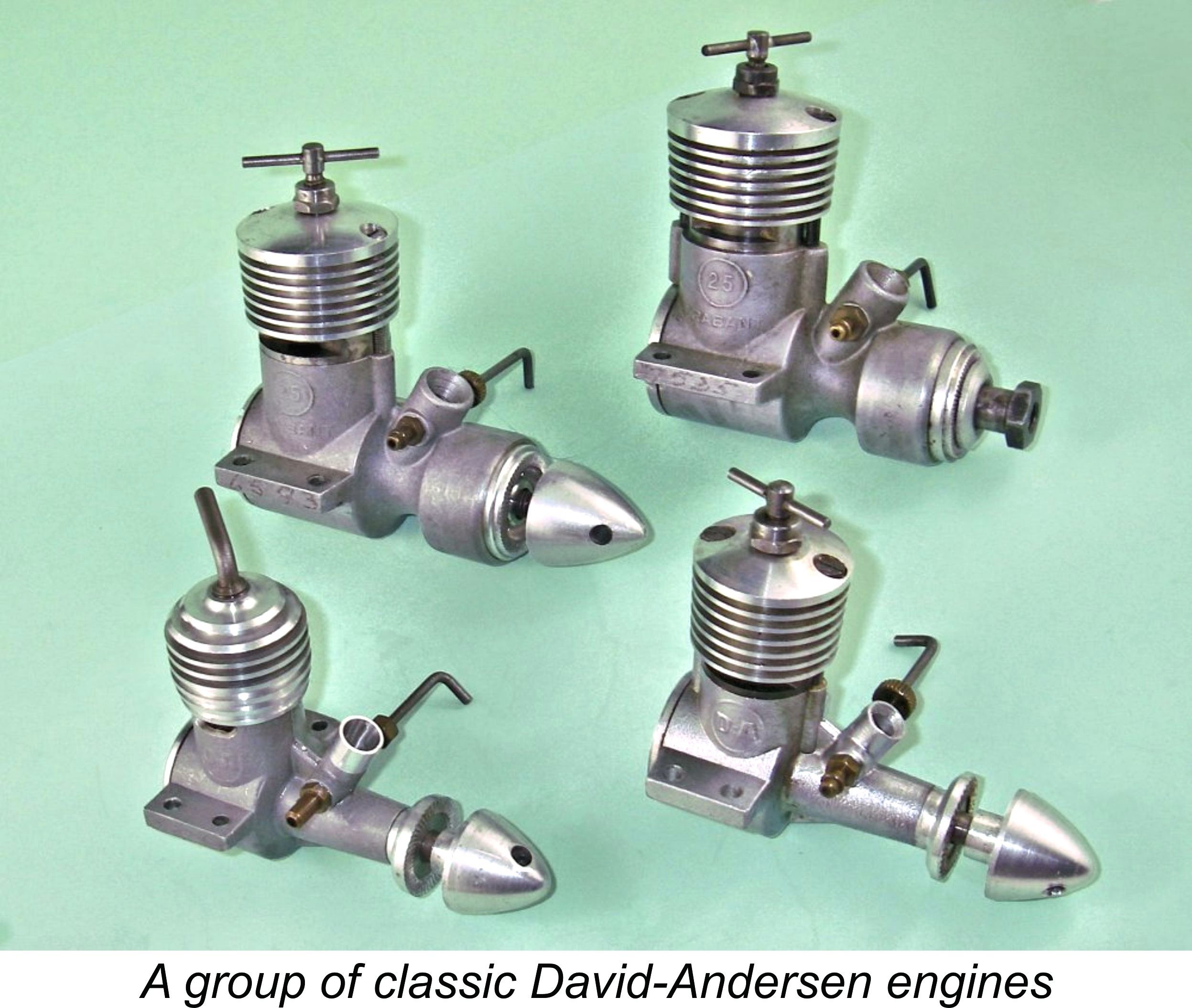 When the subject of the commercial manufacture of model engines comes up, Norway is not generally the first country which immediately leaps into one's mind. This is quite understandable when we consider that there are only three recorded producers of model engines originating in that country, all of whom had ceased commercial series production by 1965.
  Having gratefully acknowledged the above sources, I'm naturally compelled to acknowledge the fact that such sources leave much of the human interest side of the story untold. In my book, the engines themselves form only part of the story - the people who designed, manufactured and used them are every bit as important. In that context, I must now record an immense debt of gratitude to my valued Swedish friend and colleague Lars Gustafsson, who was kind enough to put me in direct contact with his friend Åsmund Johansen, a David-Andersen enthusiast living in Norway. Åsmund was most eager to help, sending me a number of images of D-A engines to which I did not have direct access.
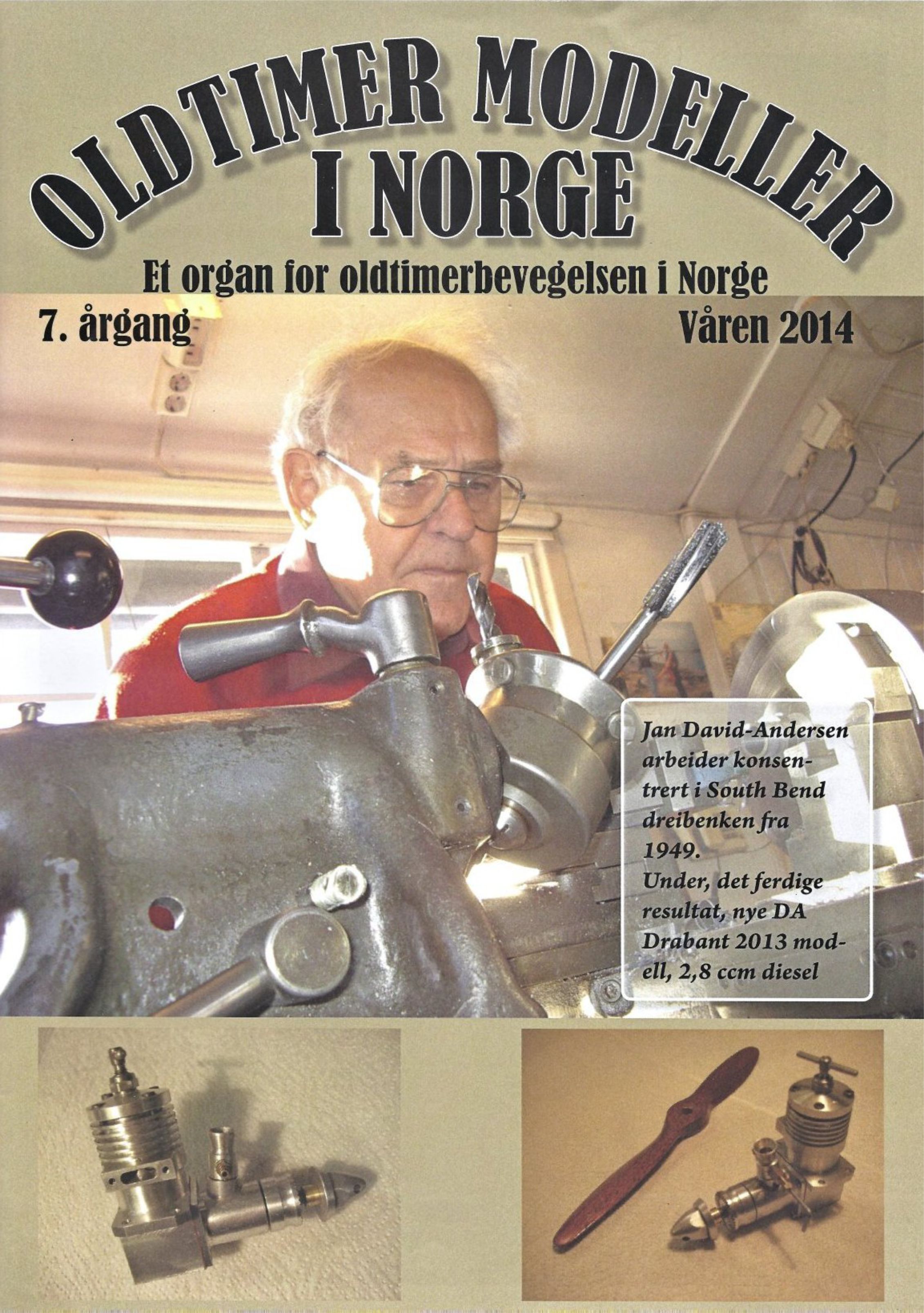 Plans for this design were featured in the Spring 2014 issue of the Norwegian vintage modelling magazine “Oldtimer Modeller I Norge”. Jan and his new design actually made the front cover of the magazine, thus clearly confirming Jan’s ongoing place of prominence in Norwegian modelling circles. Such demonstrated enthusiasm and commitment over such a long period of time can only command the highest level of respect.
  Jan David-Andersen was born in Oslo, Norway on December 16
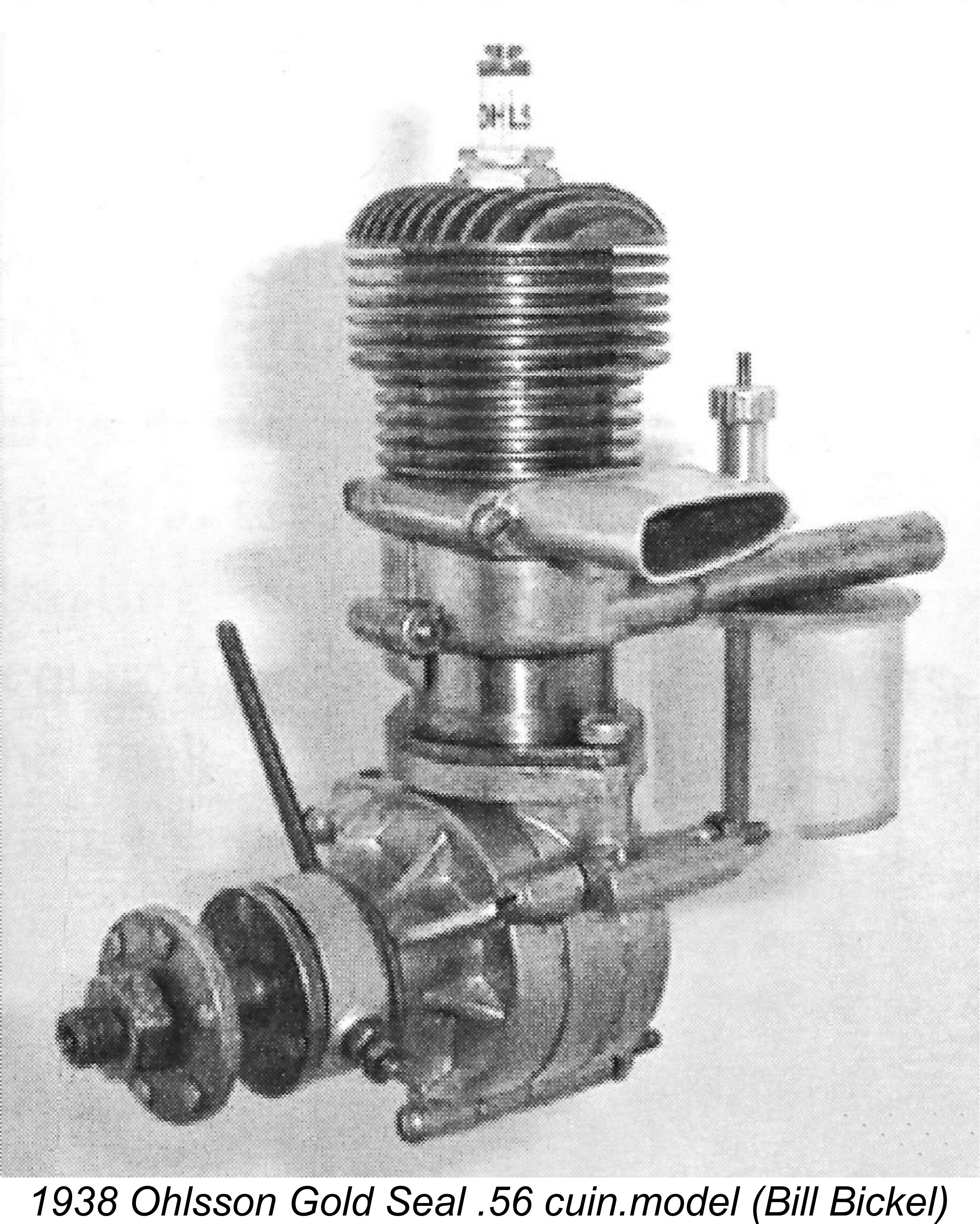 an David-Andersen’s interest in model engines actually pre-dated his awareness of the compression-ignition concept. Although no model engines of any sort had been commercially manufactured in Norway during the pre-war period, a number of imported engines from elsewhere had somehow trickled into the country, including a few Ohlssons, Browns and Atoms. The owners of these engines had formed the nucleus of an enthusiastic Norwegian power modelling community. It was apparently contact with this community that sparked young Jan’s lifelong interest in model engines.
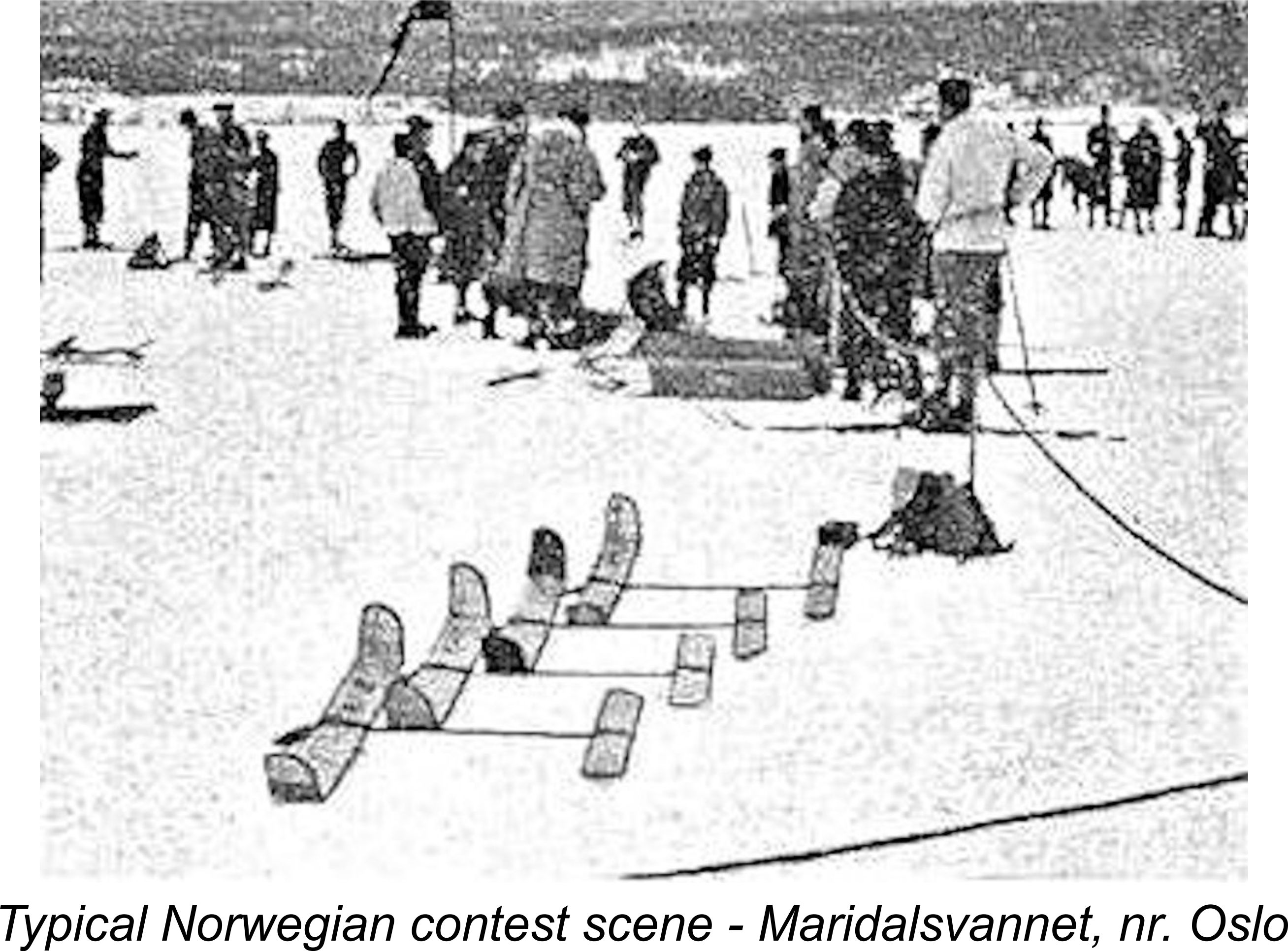 It will doubtless come as something of a culture shock to modellers from other regions of the world to learn that the main model flying season in Norway covered the winter months from October through to the following April! This was due to the lack of sufficient terrestrial open space in Norway, which is essentially a mountainous country intersected by long fjords and dotted with lakes. By contrast, once temperatures fell consistently below freezing, as they did beginning in October in most years, the country’s numerous lakes quickly became frozen over with layers of ice ranging from 6 inches to four feet in thickness! Even some of the lesser fjords froze over in this manner. The flat open expanses created by this annual event were ideal for model flying since they offered both large flat flying areas and unlimited visibility for observation and timing. Even better, model retrieval could be undertaken on skis!
  Once WW2 broke out, it did not take long for Norway to become very directly affected. On December 14
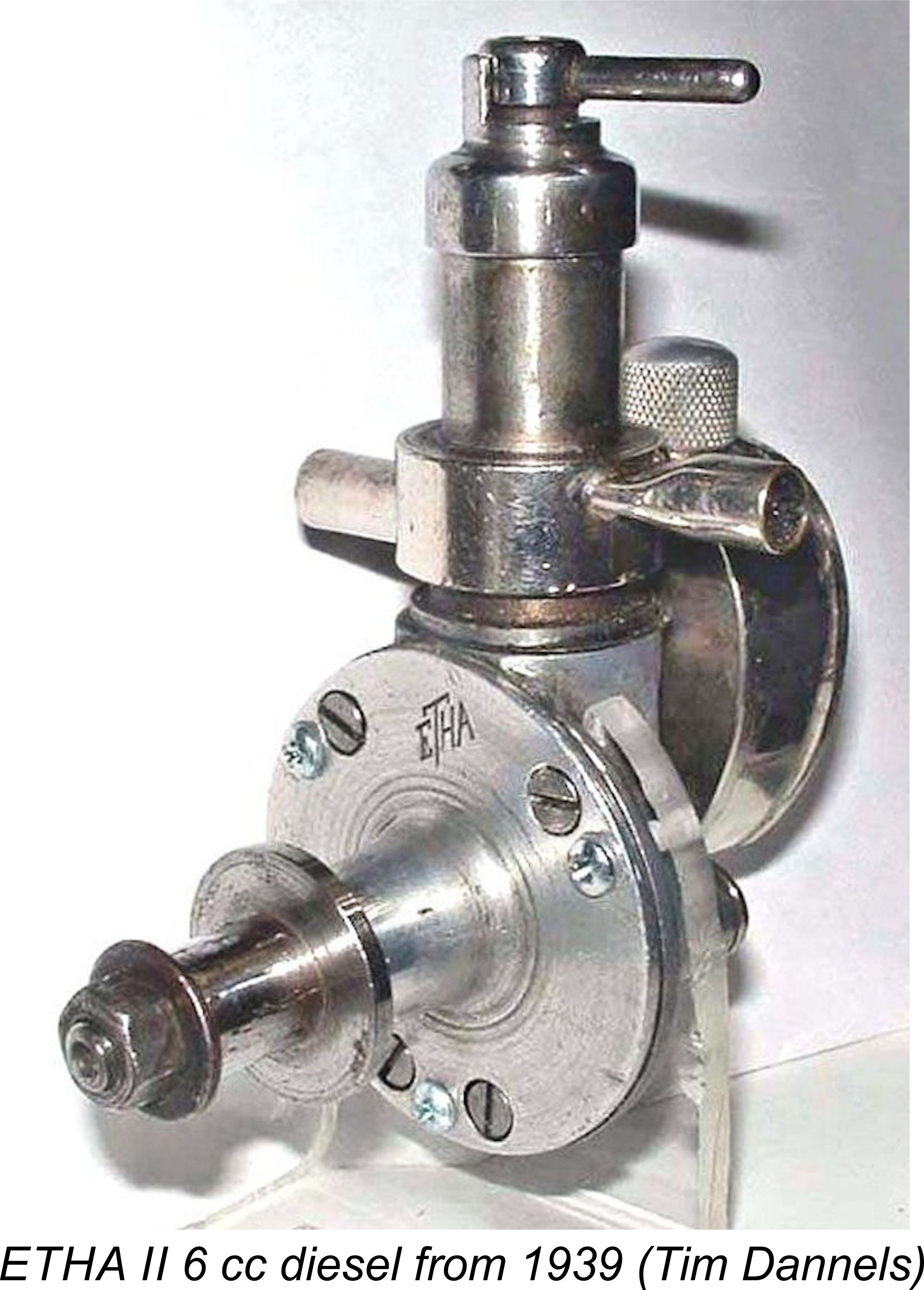
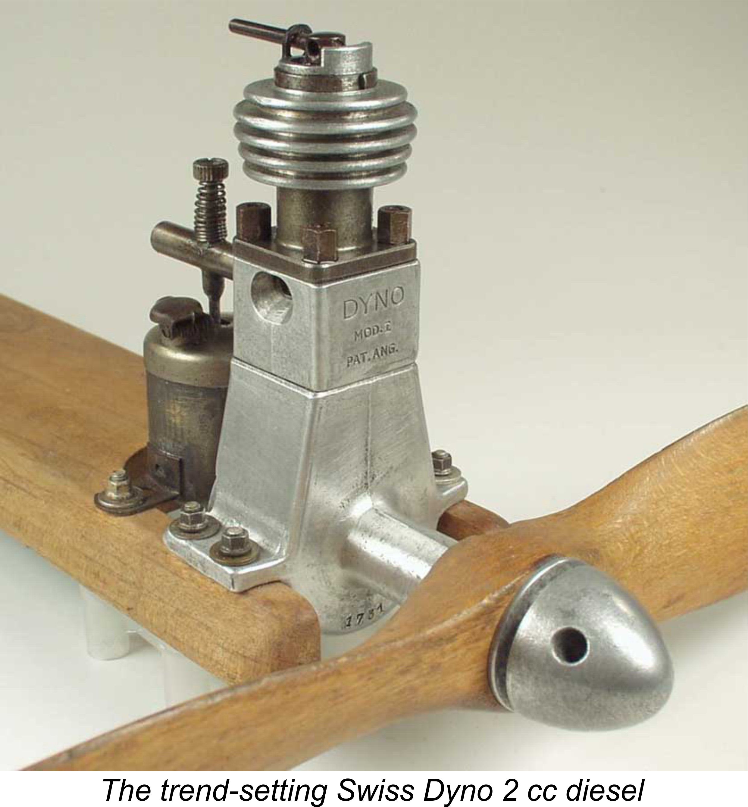 ETHA designs, being both smaller and lighter as well as having a higher specific power output. As time went on, the Dyno became one of the most widely-imitated early model diesel designs of them all.
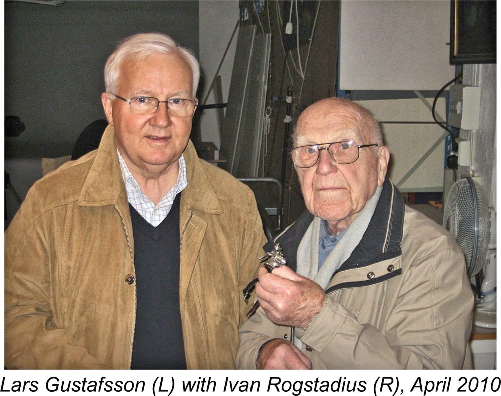
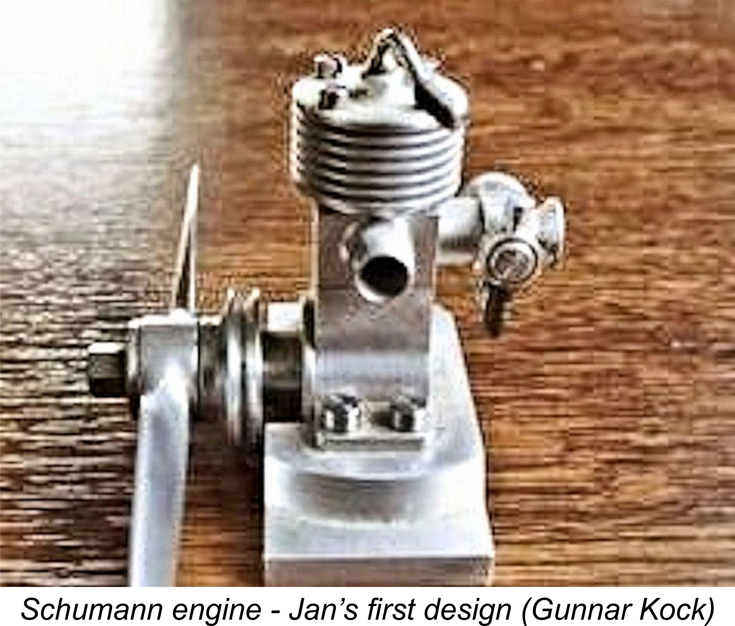 According to Gunnar Kock, Jan shared the details of one of his earliest model diesel designs with his old mentor Schumann, who proceeded to produce a few examples of what is generally known today as the “Schumann engine”. Despite its name, this actually appears to be the first model diesel engine designed by Jan David-Andersen to actually appear in the metal. Remarkably, an example survives today in the model engine collection at the Norwegian Aviation Museum in Bodø. It is this example that is illustrated here.
 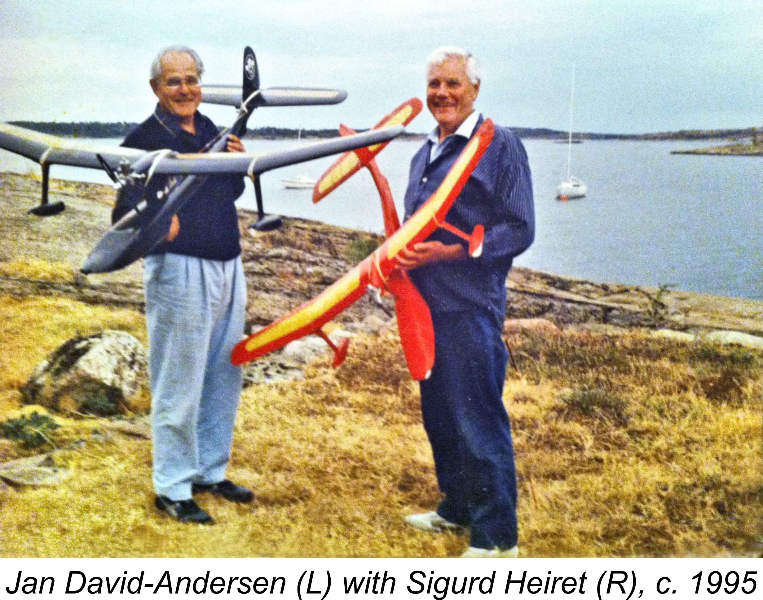 It's worth mentioning in passing that Sigurd Heiret was by no means put off by his rather "explosive" experience! He and Jan remained lifelong friends and fellow modellers. Sigurd soon became one of the first Norwegians to build a radio-controlled model, for which he also built the radio equipment. Much later still, he capped this achievement by constructing his own full-sized aircraft, a
 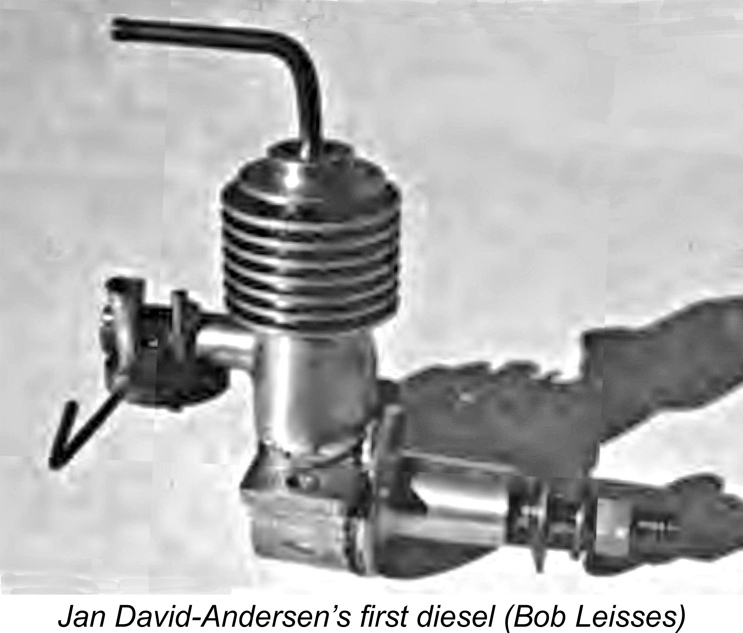 At his time of writing in 1977, Bob Leisses had managed to acquire engine number 4 of this series from its original owner Per Hof, who was a prominent member of the Oslo model flying community during the wartime and early post-war periods as well as being a well-respected model designer. Per told Bob that the engine had yielded excellent results "although it was becoming more difficult to start prior to retirement”. It was flown in a couple of free flight models, then used to power a beautiful scale Spitfire. The latter model was the centerpiece at a post-war Royal Norwegian Air Force reunion, being inspected by the King himself on that occasion.
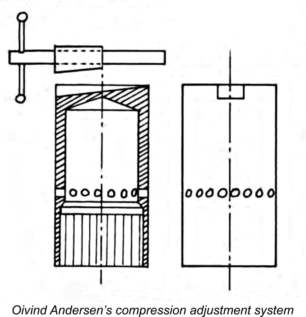 Øivind’s engine featured fully variable compression, albeit with neither an eccentric main bearing nor a contra-piston being used. Instead, the blind-bored cylinder liner was a honed push fit in a bore accurately machined into the cast aluminum crankcase. In this, it paralleled the “moving liner” designs from elsewhere such as the Delmo and Speed Demon diesels. However, the really unique feature was the way in which the vertical movement of the liner was regulated. The liner was moved up and down by the wedging action of a tapered steel nut sliding in a wedge-profile slot formed on top of the cylinder. This nut was activated by a “compression screw” set at right angles to the bore. Hopefully the attached sketch will make this arrangement clear. The design also kept the cylinder from rotating in the case, thus maintaining port alignment. It had the added advantage of minimizing the engine’s height.
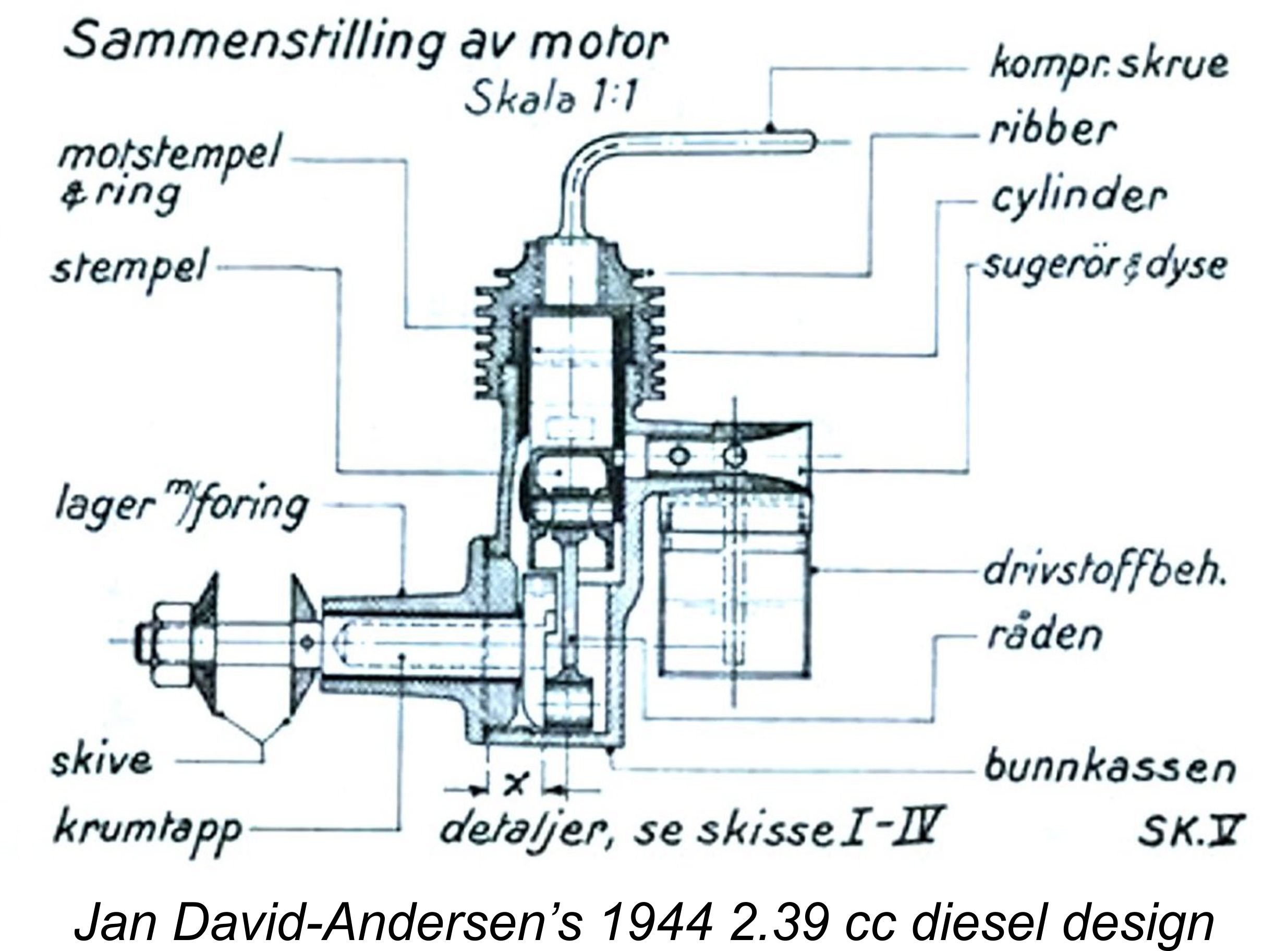 Returning now to Jan David-Andersen’s wartime activities, further refinement of his pioneering 3.5 cc design resulted in the development of an improved 2.39 cc version of the engine. This revised model had bore and stroke measurements of 13 mm and 18 mm respectively. Hopefully the attached drawing taken from Jan’s previously-mentioned book will make the general constructional details clear.
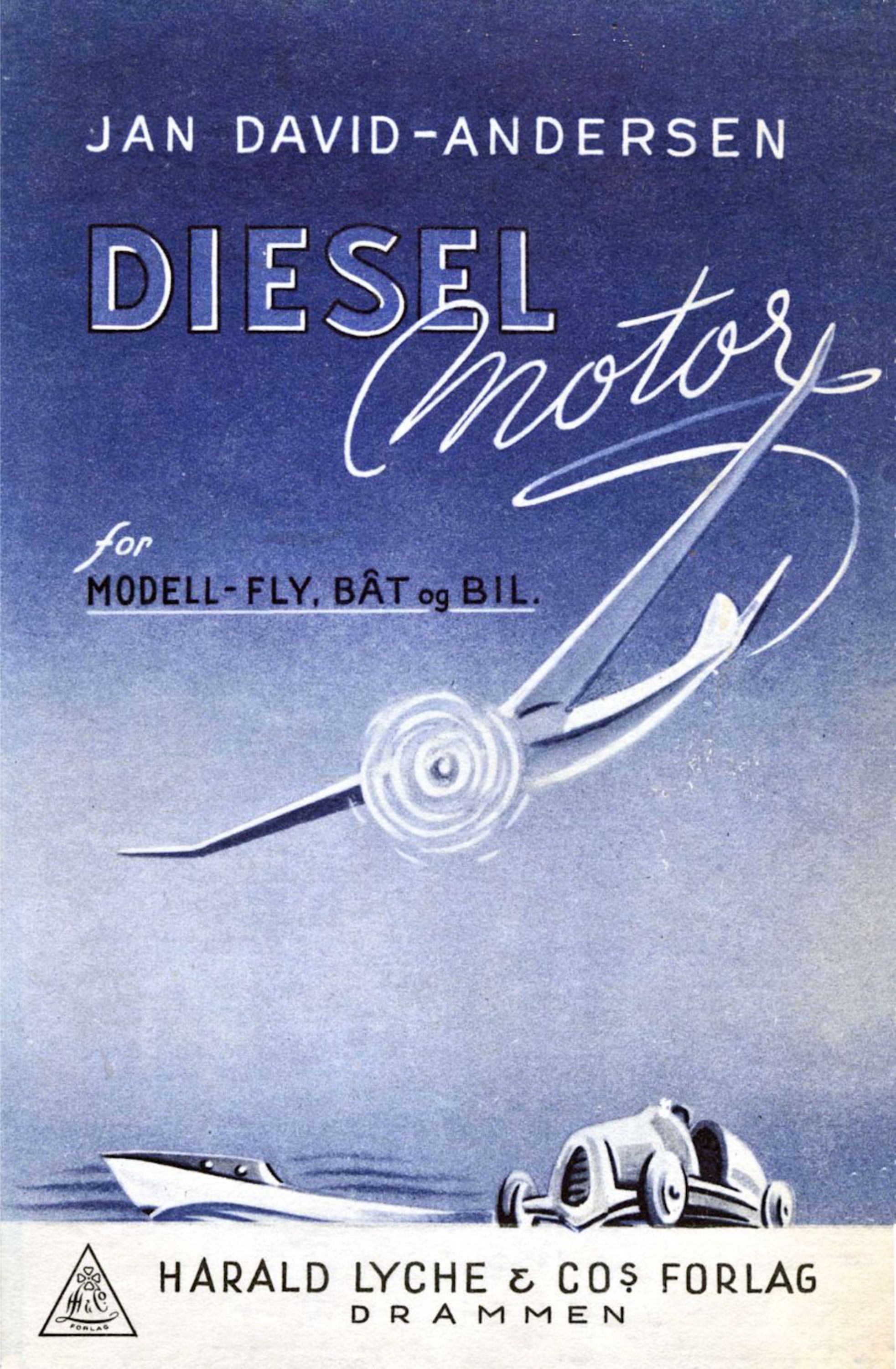 Feeling that this model was sufficiently well developed to merit the attention of his fellow power modellers, the 23-year old Jan was inspired to write a book in which the technology of model compression-ignition engines was explained along with plans and detailed building instructions for his 1944 2.39 cc design. The title of this book was (in Norwegian, naturally!) “Diesel Engines for Model Aircraft, Boats and Cars”. This book was published by Harald Lyche & Co. Forlag of Drammen in January 1945 at a time when WW2 was still ongoing, making it almost certainly the first-ever book on model diesel engines.
 Upon his return to Oslo in the latter part of 1947, Jan found himself armed with a considerable store of knowledge and experience in the precision engineering field but without the equipment to put those assets to practical use on his own account. It was at this point that fate intervened. Beginning in April 1948, the United States implemented the European Recovery Program (ERP), better remembered today as the “Marshall Plan” after Secretary of State George Marshall, who was one of the Plan’s primary supporters. Recognizing that the restoration of prosperity in war-ravaged Europe was very much in the best business interests of the United States, the latter country eventually provided a total of $13 billion in economic and technical assistance to recovering countries. One recipient of this largesse was Norway, which received a total of over 3 billion kroner ($372 million) in aid despite the underlying opposition of conservative Norwegian business interests who feared the competition that the Plan might engender.
 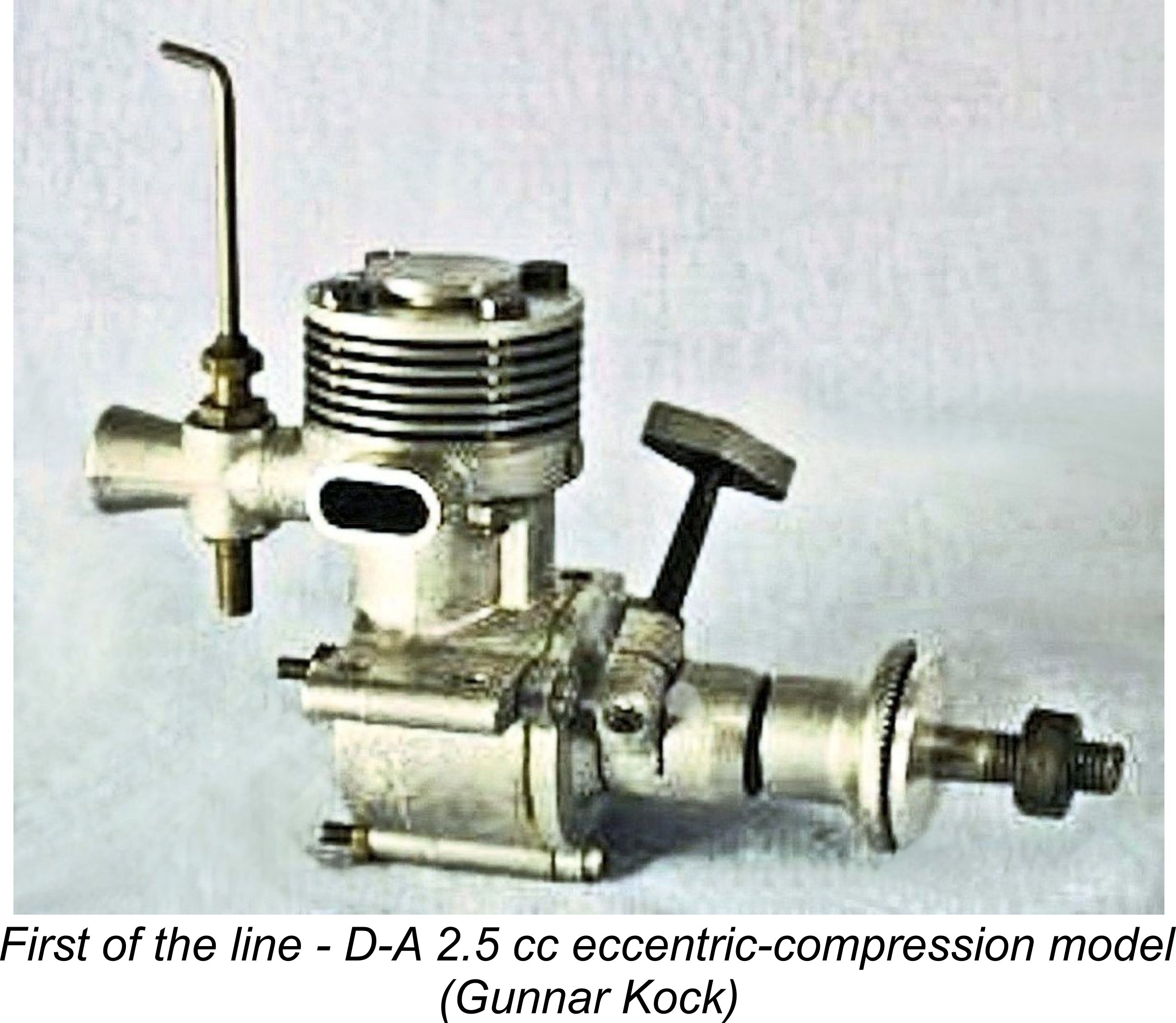 In this design, the crankshaft ran in a plain bearing which had an eccentrically-bored sleeve. This sleeve could be rotated within the bolt-on main bearing housing, causing the axial centre-line of the crankshaft to change its elevation relative to the rest of the engine. In particular, the vertical position of the piston at top dead centre was changed by this action, thus changing the compression ratio. In effect, the piston did double duty as both the working piston and contra piston, with the con-rod fulfilling the role of the compression screw.
 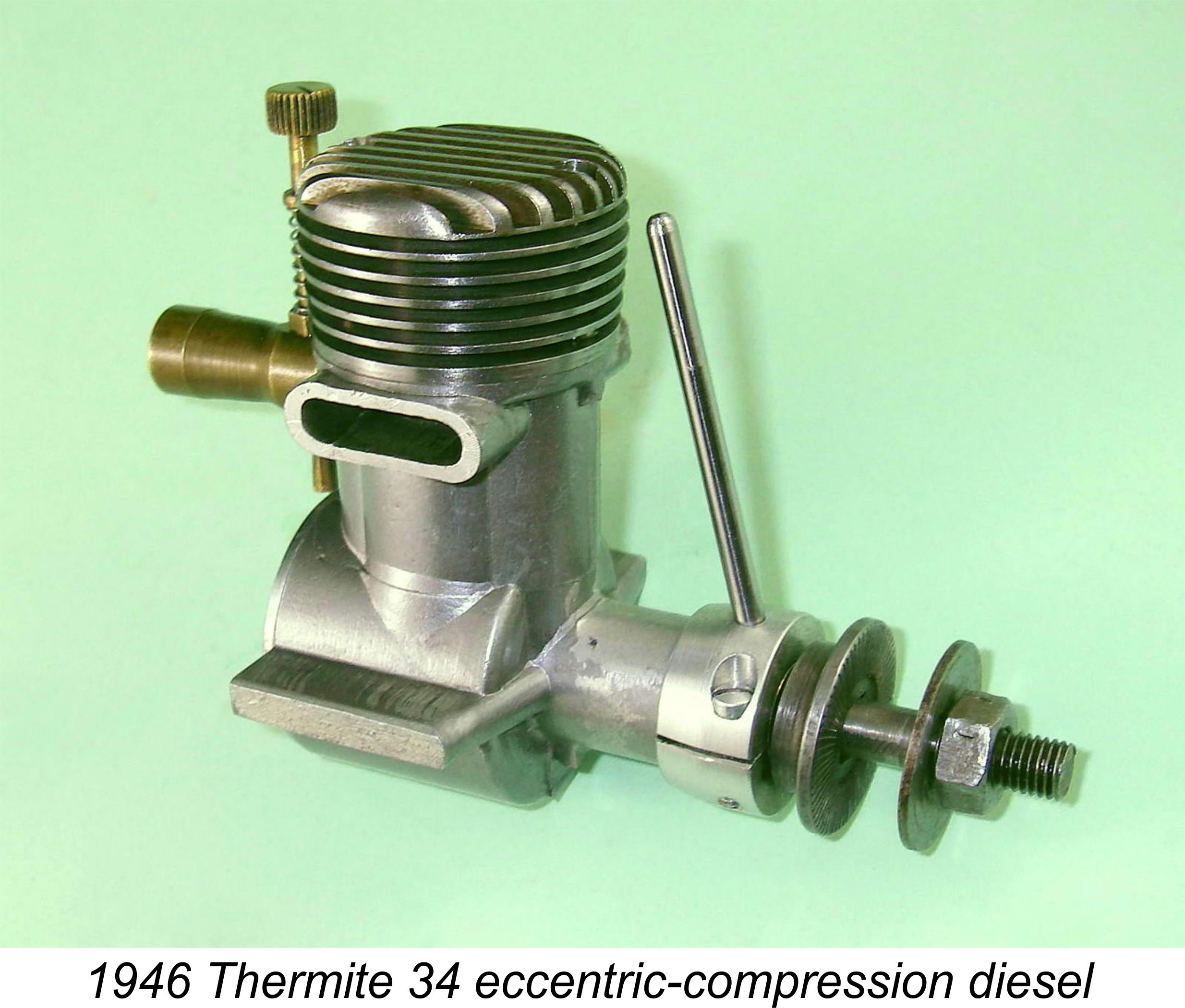 The other issue with this system was the fact that rotating the eccentric bearing sleeve moved the axial centre-line of the shaft laterally as well as vertically. The consequence of this was that the horizontal shaft axis would be displaced to one side or the other of the vertical axis of the bore. An engine having this feature is said to be of the
 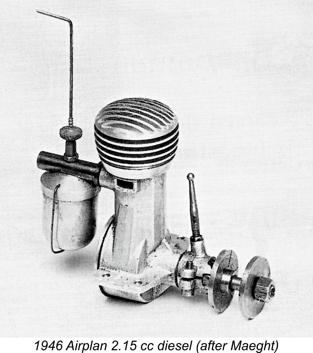 Nonetheless, the very rapid pace at which model diesel development was advancing during this period meant that this design was something of an anachronism by 1950 standards. The sideport induction system was well along in the process of being almost universally supplanted by rotary valve induction, while the eccentric compression adjustment system was generally considered obsolete, having disappeared from the marketplace by 1949 following its pioneering application by such makers as Airplan and Ouragan in France,
 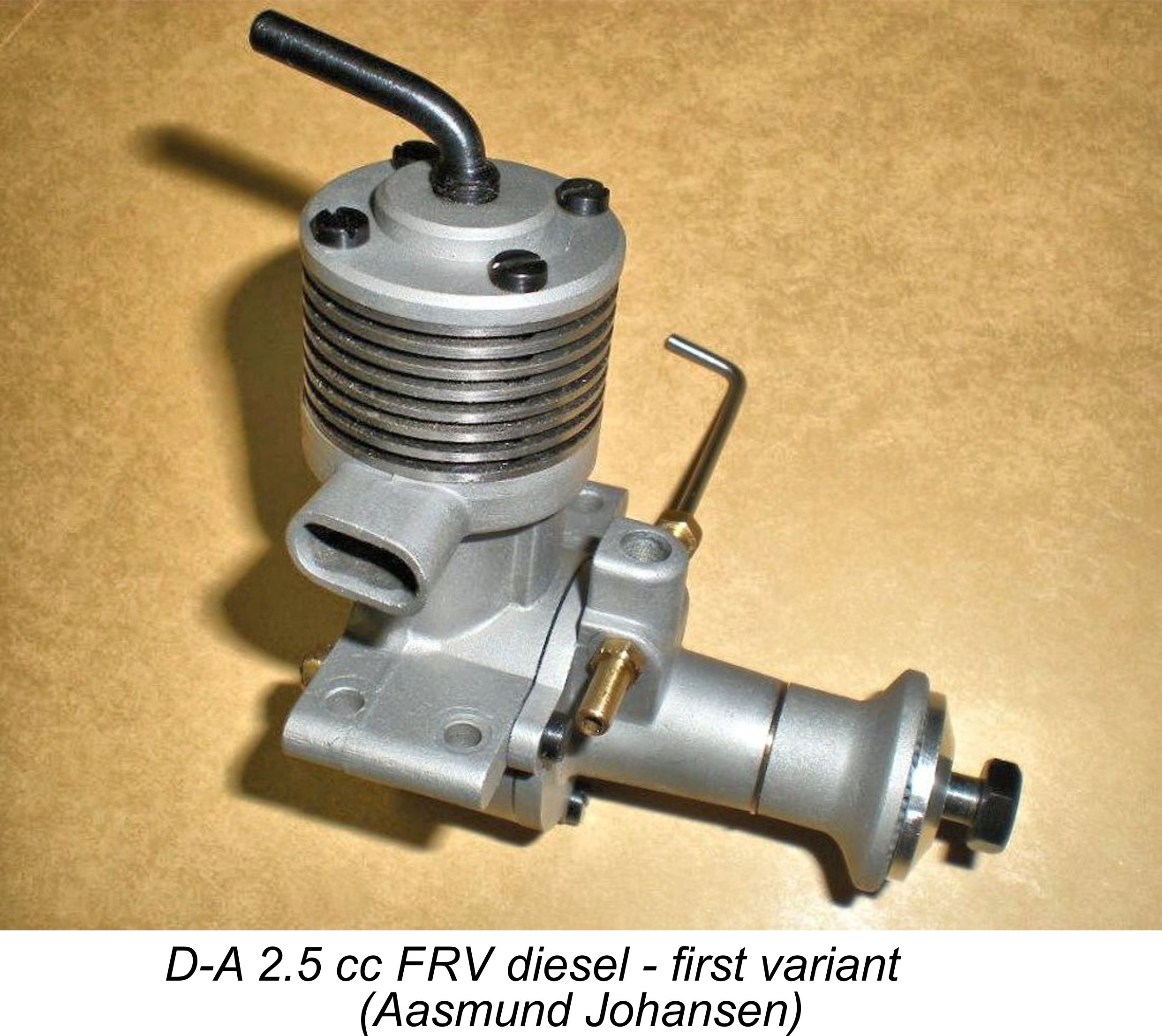 This first variant of what was to be a series of long-stroke plain-bearing FRV models had a plain cast un-finned head featuring a “step“ in the middle to provide additional support for the comp screw thread. It also incorporated an unusual D-shaped FRV intake venturi cast integrally onto the bolt-on main bearing housing. It retained the integrally-cast exhaust collector ring with two oval stacks, one on each side, that had distinguished its eccentric-compression predecessor. Further evidence of its ancestry was to be seen in the form of a vestigial stub where the side-port induction tube had been positioned on the earlier model. The presence of this stub confirms that the crankcase casting for this model was produced from a modification of the original 1950 die.
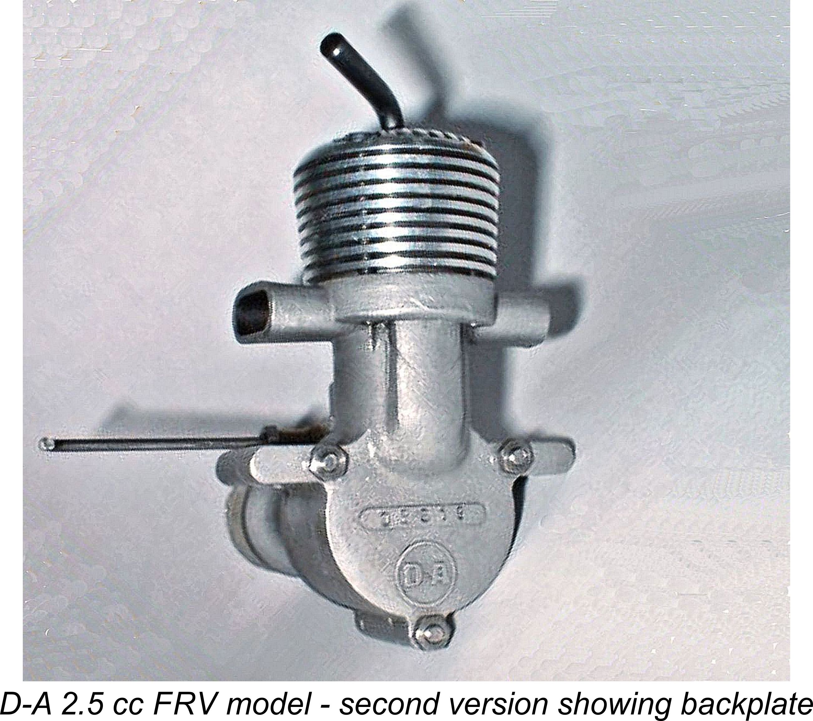
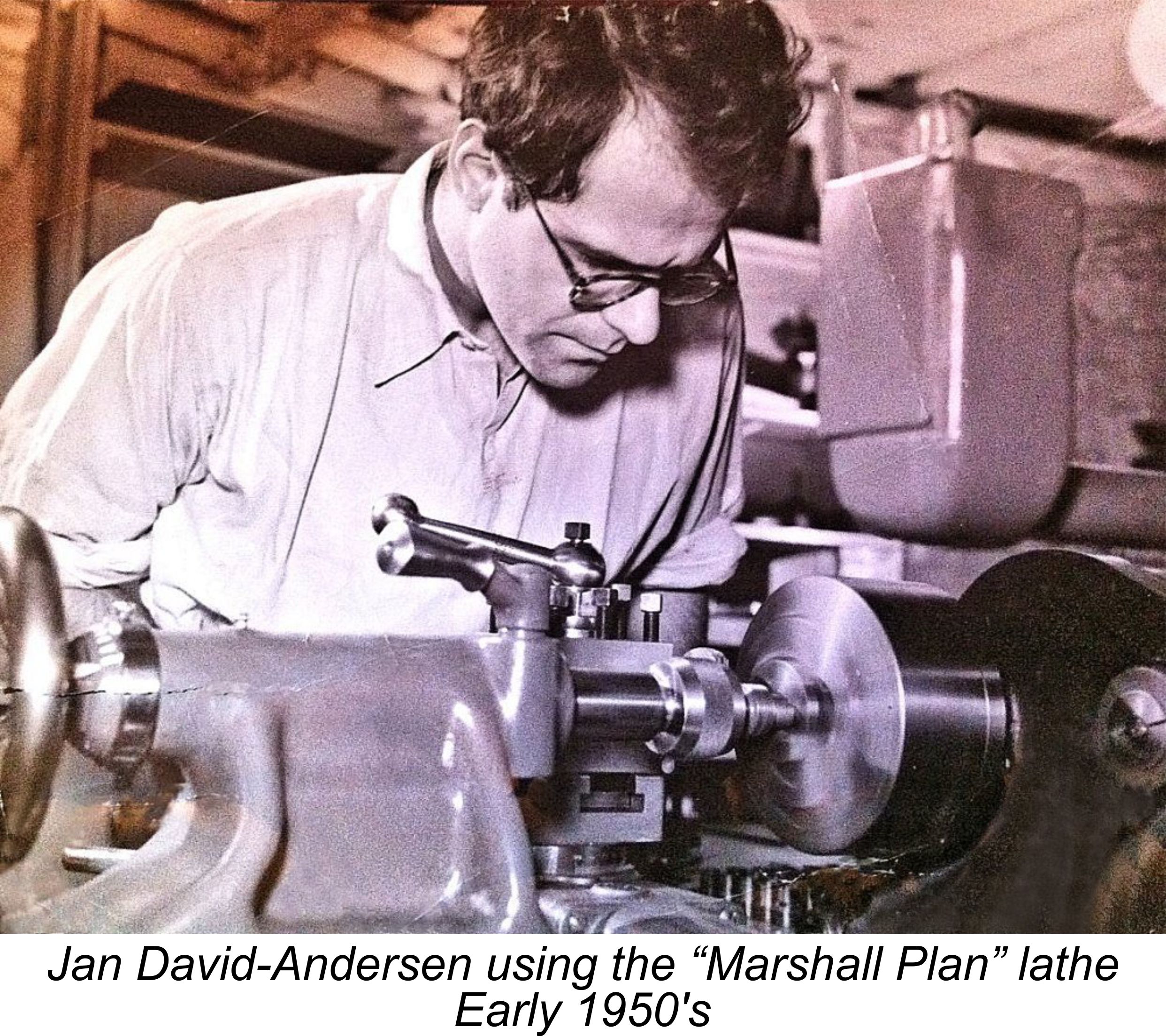 This version of the D-A 2.46 cc diesel was produced from late 1950 until the first half of 1954, consequently being manufactured in relatively substantial numbers. The design quickly became recognized as a well-made, fine-handling and dependable unit which developed unusually high torque for an engine of its displacement. As a result, it found ready purchasers both in Norway and elsewhere. Because of its easy handling characteristics and low fuel consumption as well as its excellent torque, it gained great favour among beginners and sport fliers, also achieving some success in team racing.
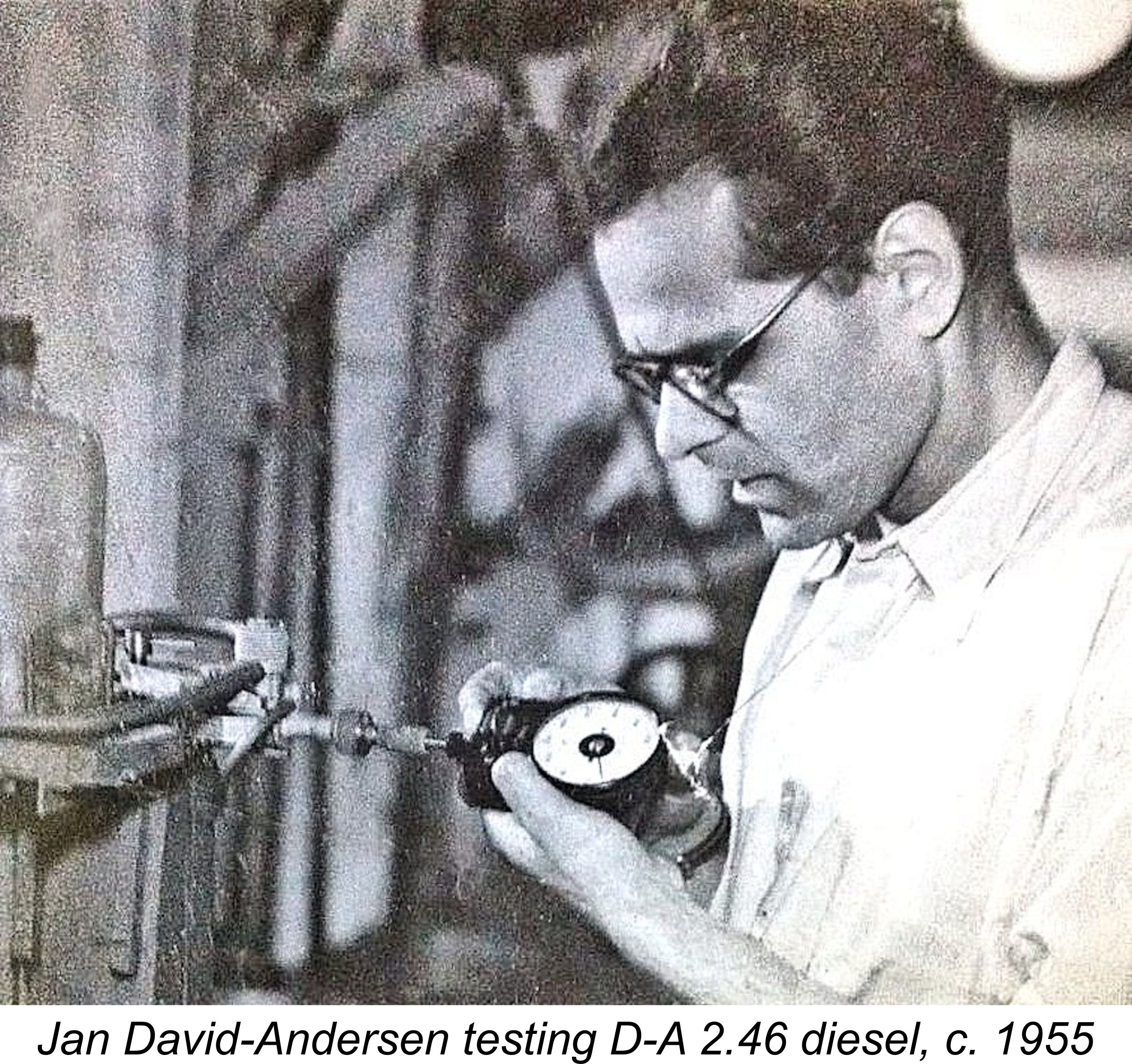 testing one of his twin-exhaust 2.5 cc models at around the same time. Our thanks to Bjørn David-Andersen for so kindly providing these and other family photographs wich appear in this article.
 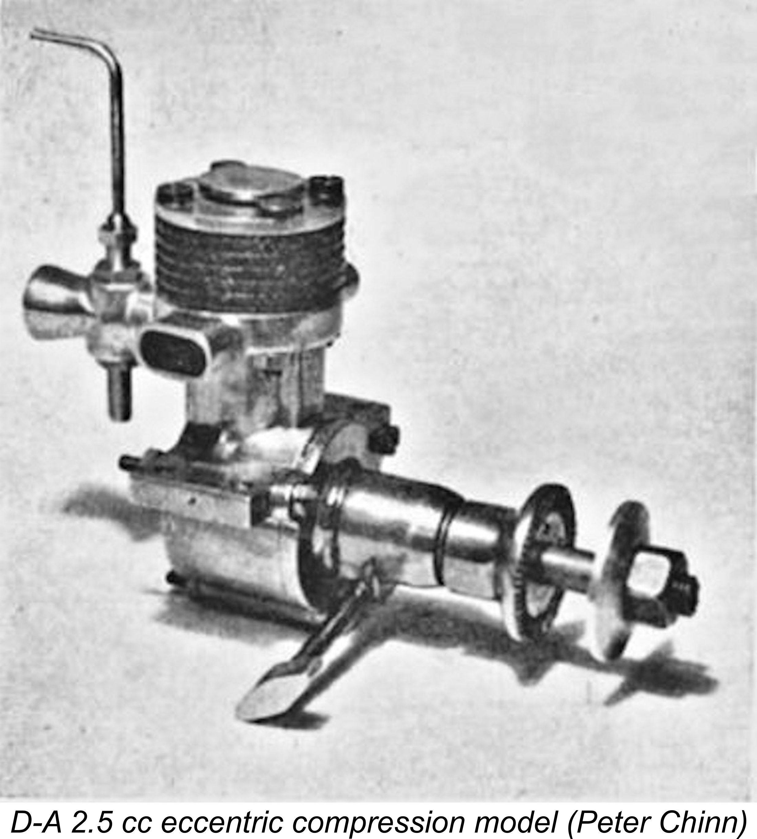 Jan personally brought examples of both variants of the original 2.46 cc model to Britain in early 1951 for the express purpose of obtaining Chinn’s comments upon the designs. The fact that Jan brought both the eccentric-compression and FRV models for Chinn to examine confirms that he was still actively marketing the eccentric-compression variant at the time.
 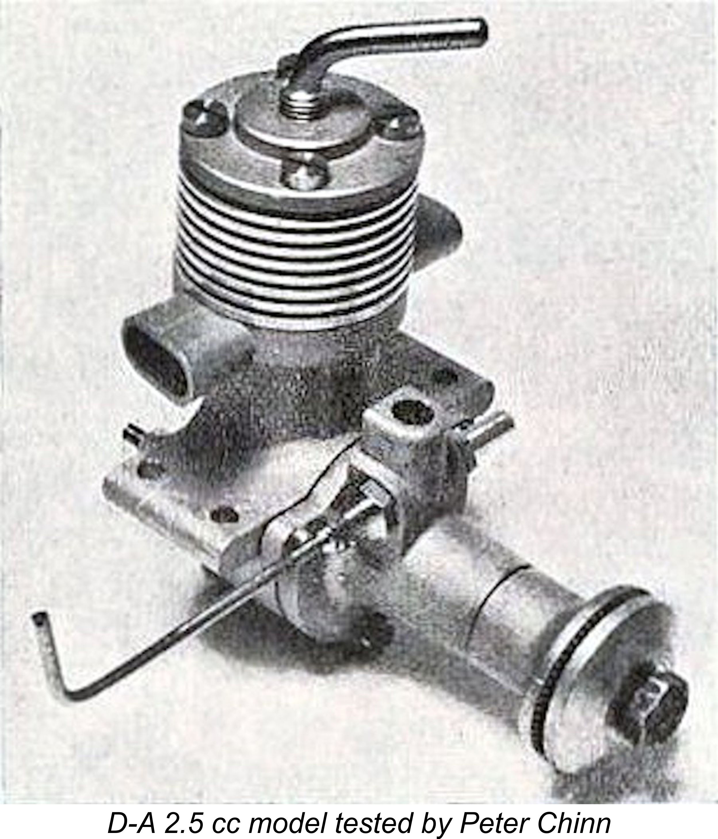 In this respect, the D-A 2.46 cc diesel received very high marks from Chinn. Starting was characterised as “extremely easy”, only a few choked flicks being required as a preliminary. Priming through the exhaust ports was found to be unnecessary either hot or cold. Once running, response to the controls was found to be very good, without being unduly critical. The engine proved to be extremely flexible in terms of its ability to be “throttled down” using the compression control alone – a real advantage for trim flights.
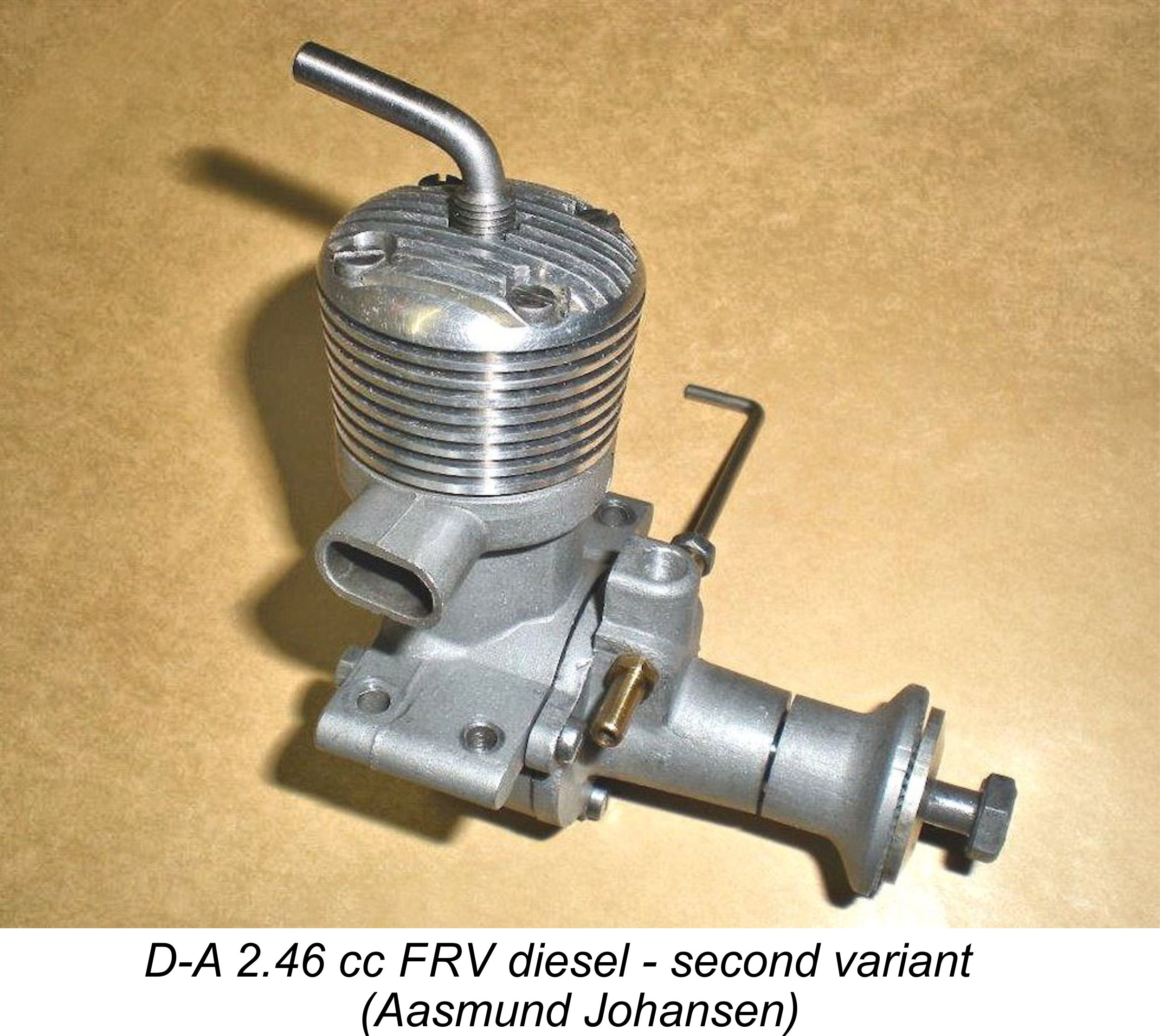 1953 issue of “Model Airplane News”. An equally complimentary report on the David-Andersen 2.46 cc model appeared in the June 1955 issue of the same magazine. Comments of this sort led to the David-Andersen range being picked up by World Engines, who became their US distributor.
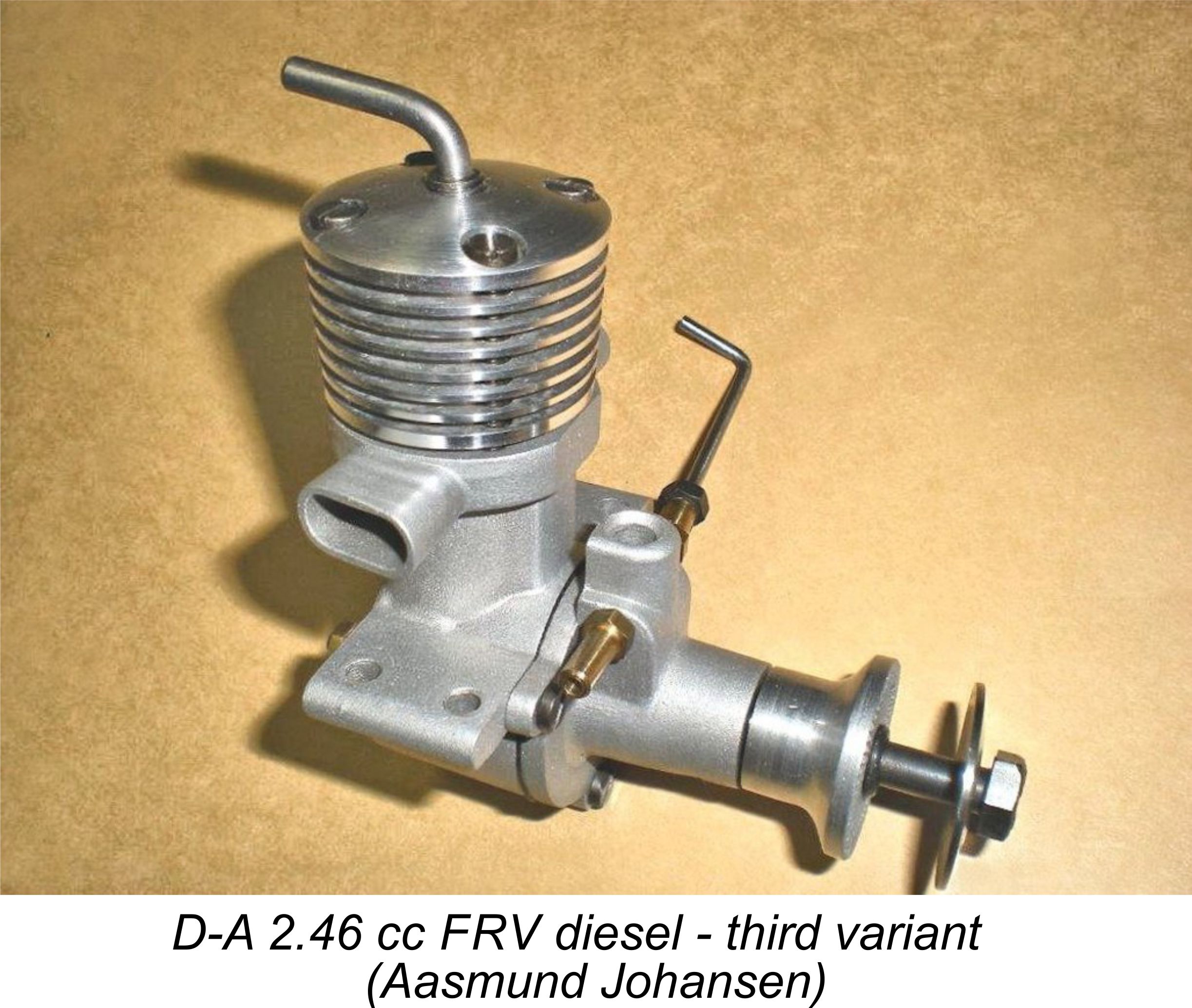 This latter version was produced in relatively small numbers, with the model being finally withdrawn altogether in early 1957 in anticipation of the introduction of the D-A Drabant 2.5 cc diesel of far higher performance. More about that model later in its place ……..
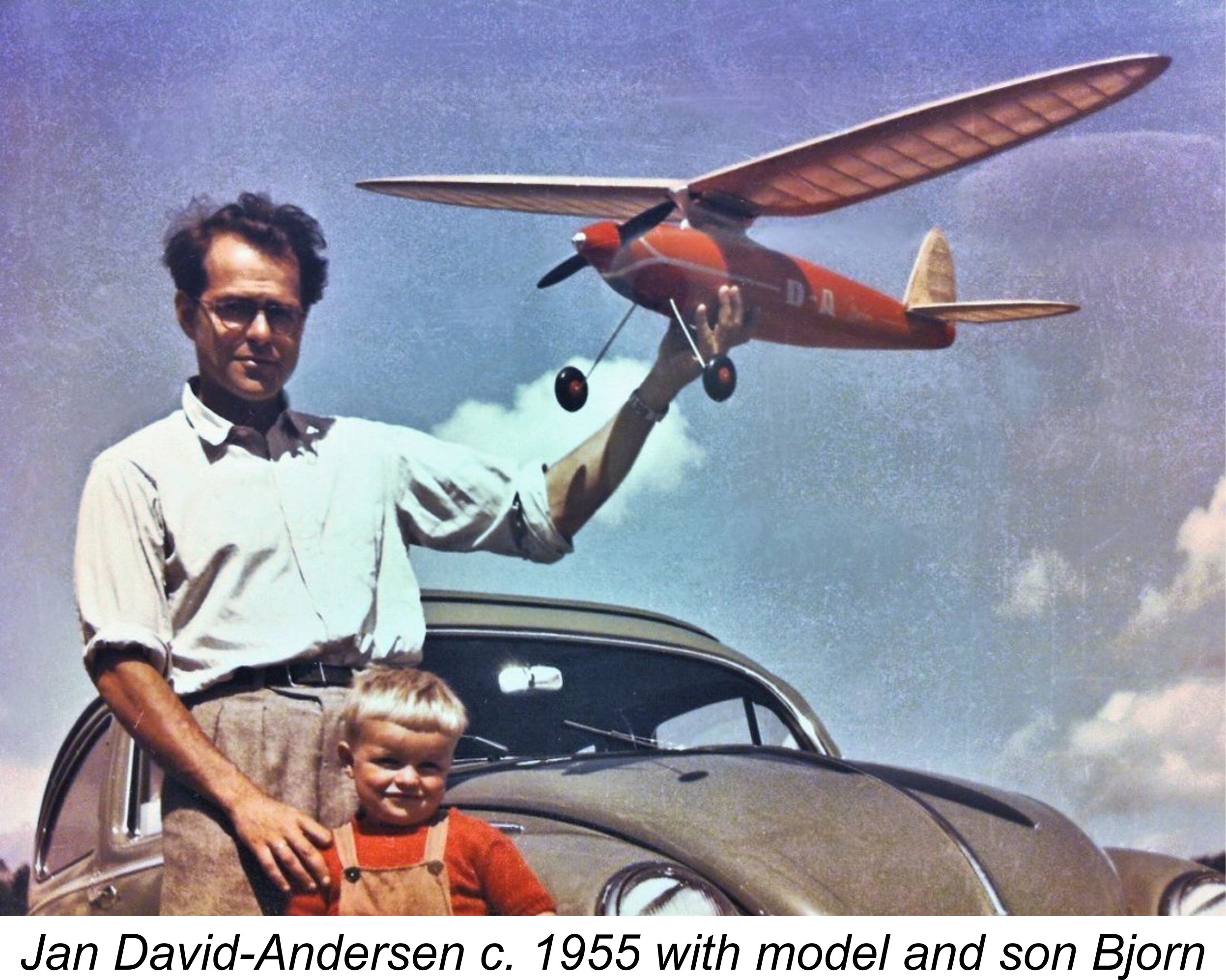
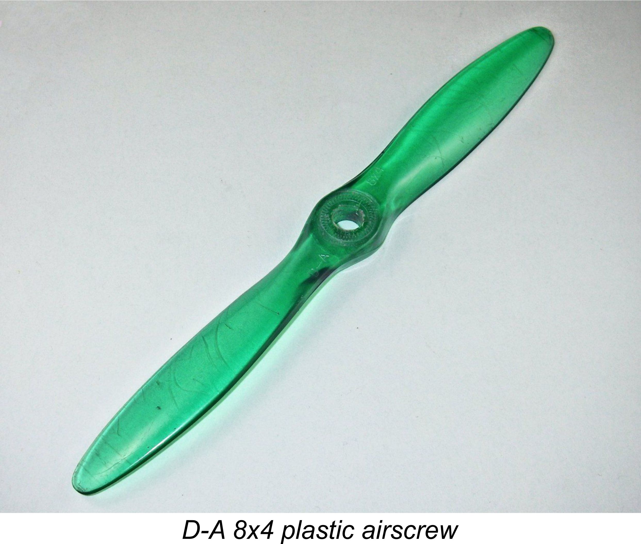
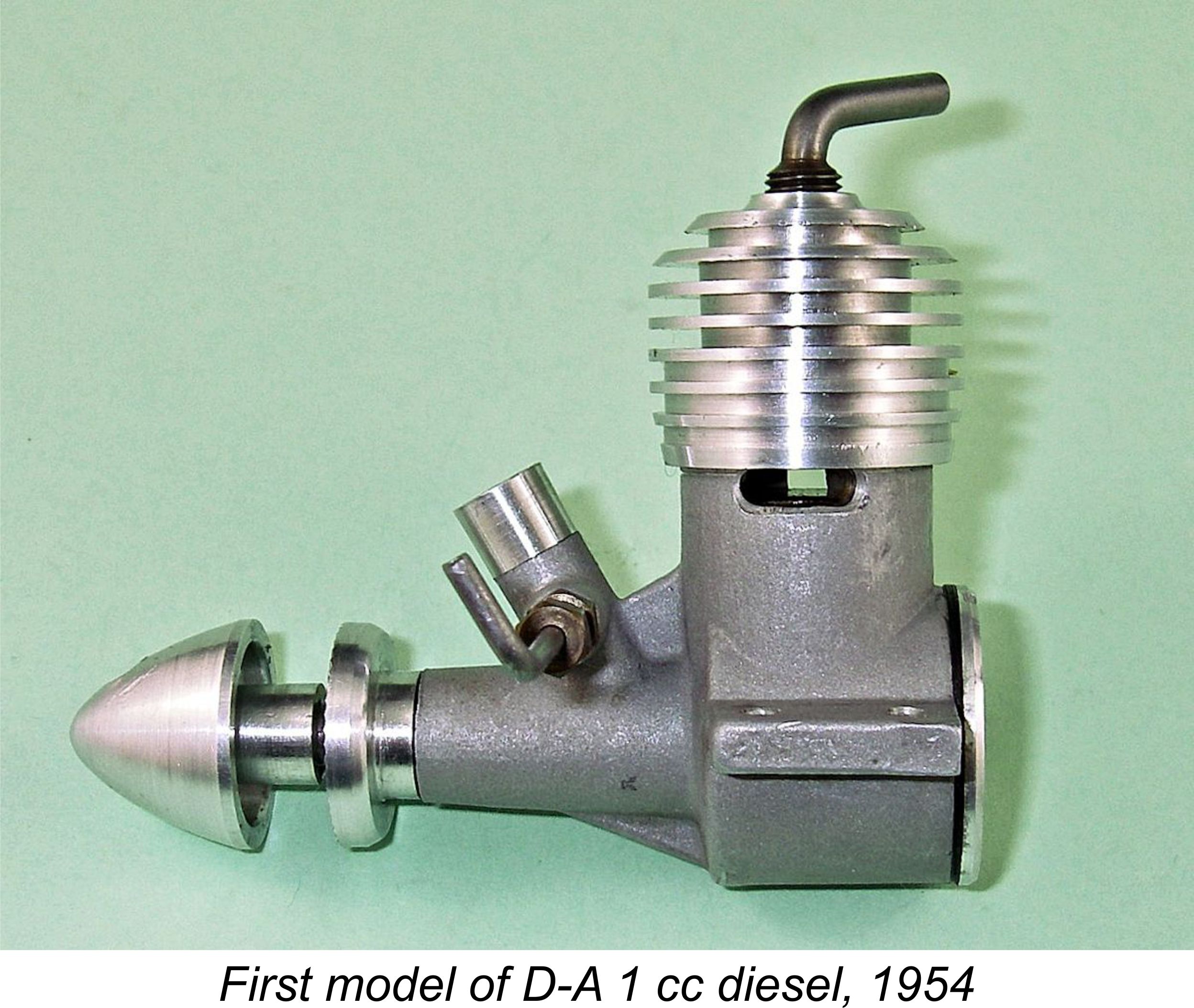 The resulting engine appeared on the market in around July 1954. It featured identical bore and stroke measurements of 11 mm each for an actual displacement of 1.05 cc (0.064 cuin.). The engine weighed in at a checked 73 gm (2.57 ounces).
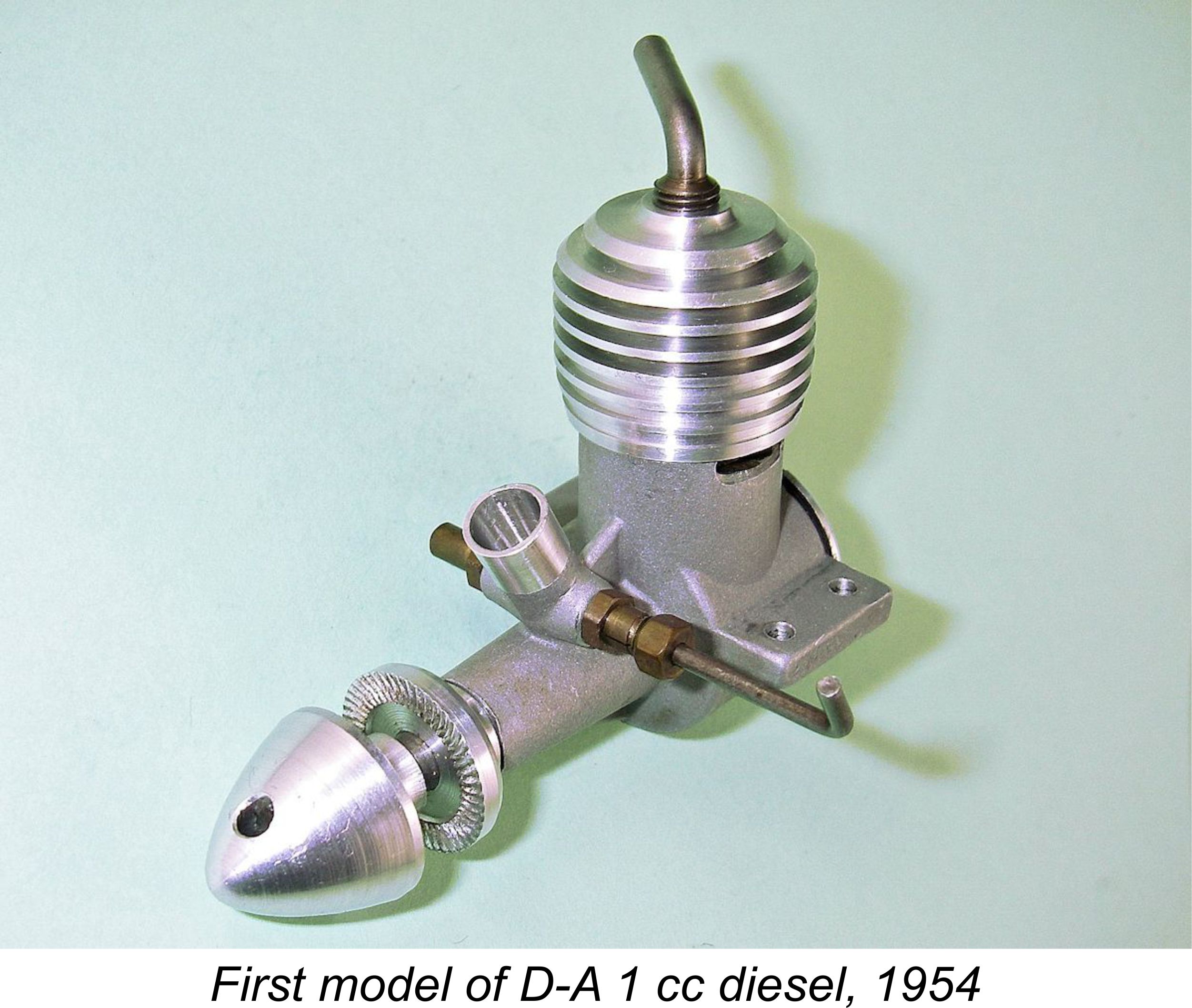 Two transfer ports of similarly generous proportions were formed between the exhaust ports. To keep them centred between the two exhaust ports, these too were necessarily aligned obliquely relative to the engine’s longitudinal axis, being supplied by an annular channel machined into the crankcase casting. In Peter Chinn’s view, the oblique orientation was adopted primarily to position the relatively large transfer ports so that they could not foul the ends of the gudgeon (wrist) pin. A location spigot and slot were provided to ensure the correct cylinder orientation during assembly.
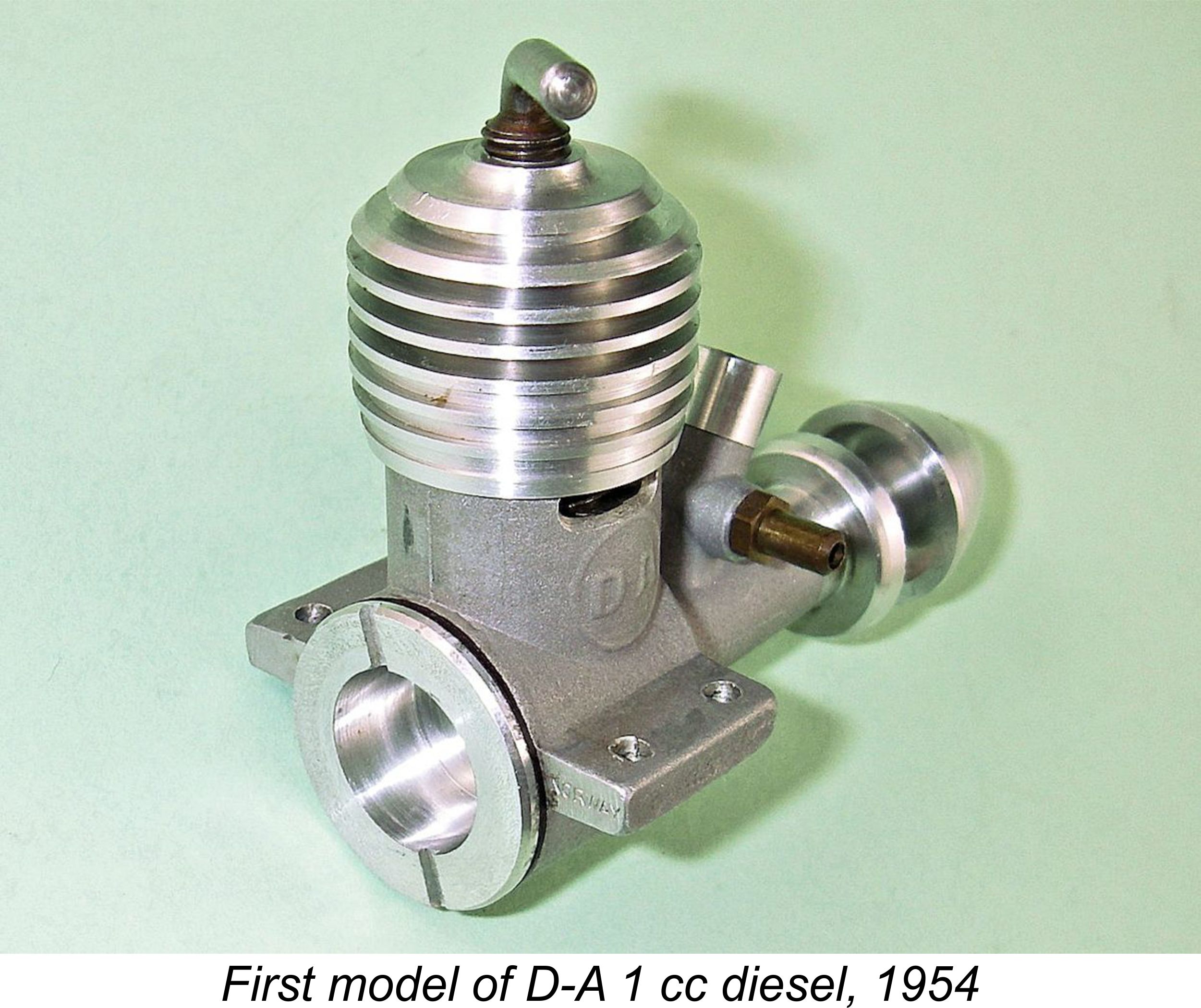 Chinn summarized this engine as “a finely constructed, robust engine of excellent performance (which) is a worthy addition to the ranks of 1 cc units”. Jan David-Andersen could scarcely have hoped for a more ringing endorsement from one of the world’s leading authorities on model engines!
 By 1957 the well-established D-A 2.5 cc long-stroke design was entering its seventh year in production in its various guises. Although it had helped to establish the David-Andersen name as being synonymous with quality and dependability, it had not set any records for performance, being rightly seen as an excellent choice for sport flying as opposed to all-out competition.
 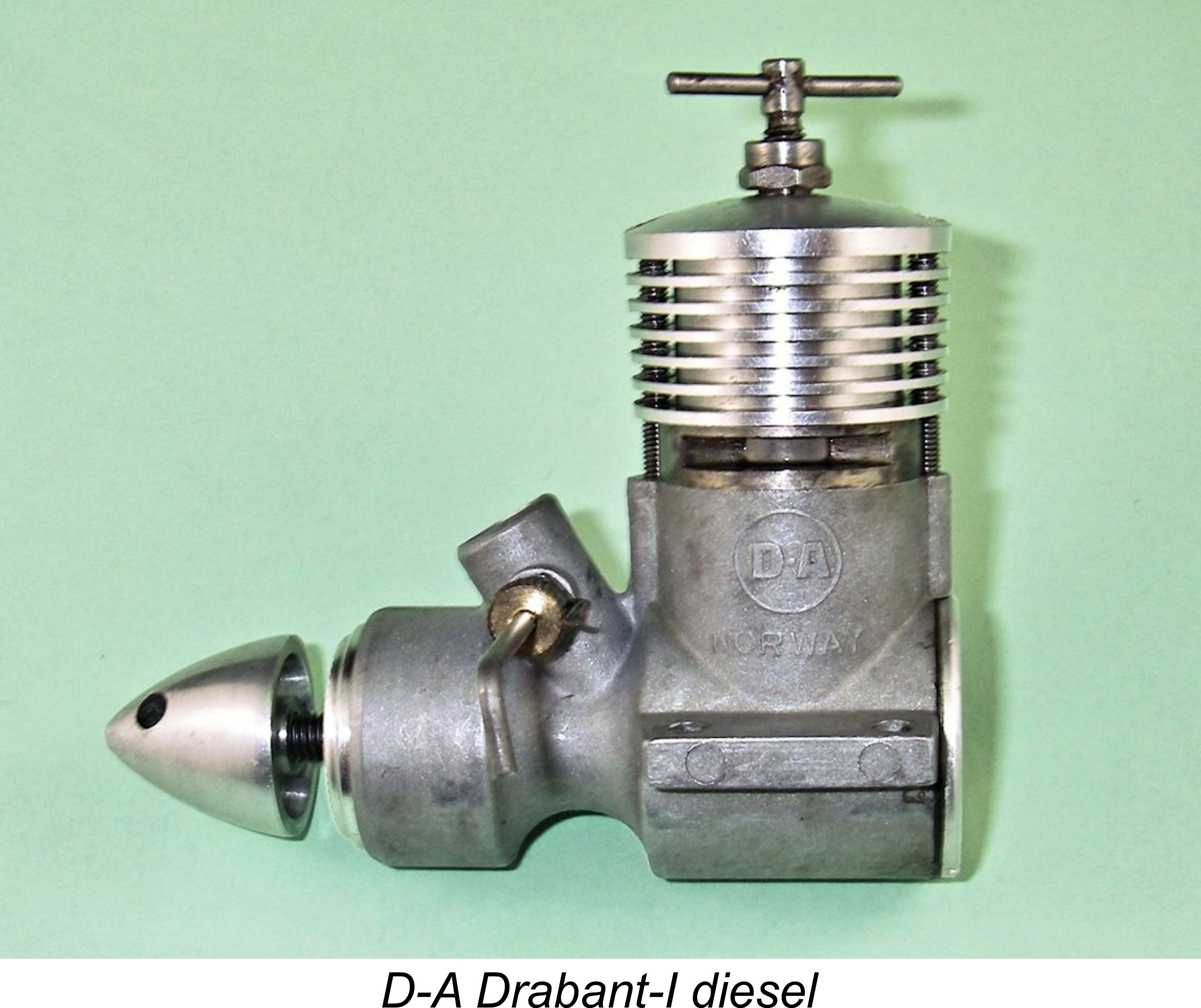 The most immediately obvious such feature was the system of mounting the compression screw. The problem of compression screw run-back had always been a bugbear of model diesels, particularly as the contra-piston became worn with use. The Drabant got around this issue very elegantly indeed by utilizing a separate internally-threaded steel carrier to accommodate the comp screw. This carrier was splined and was pressed into the head from below, thus being very securely fixed in the head. The upper end of the carrier was split, a gland nut being used to tighten the split portion onto the comp screw and thus secure the setting. A very elegant solution which was to be carried through on all future D-A production models.
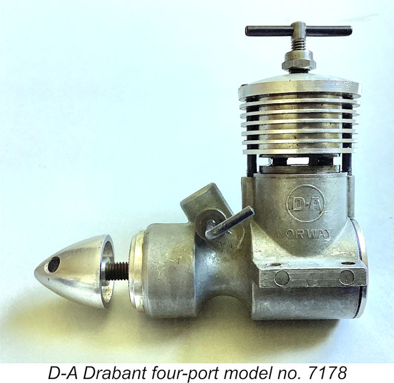 type, showing that engines featuring the four-port cylinders were distributed throughout the serial number range rather than being confined to the early examples. The transfer ports were supplied by short vertical flutes formed on the outside of the lower cylinder wall.
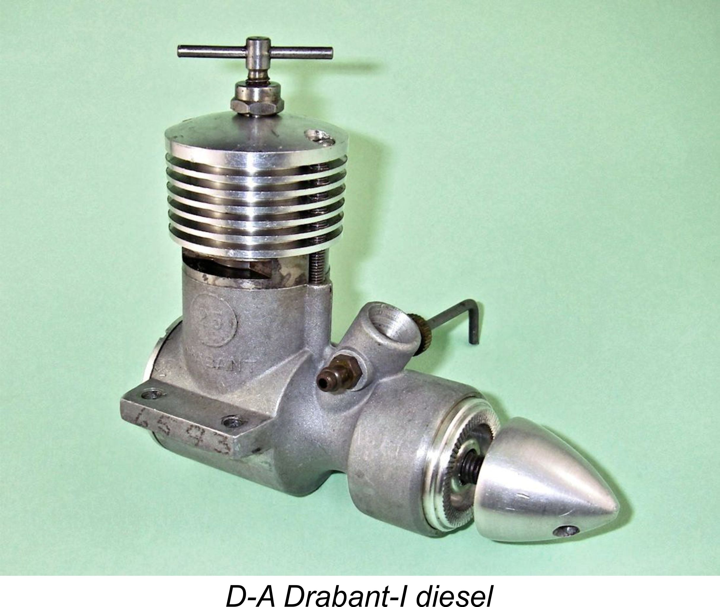
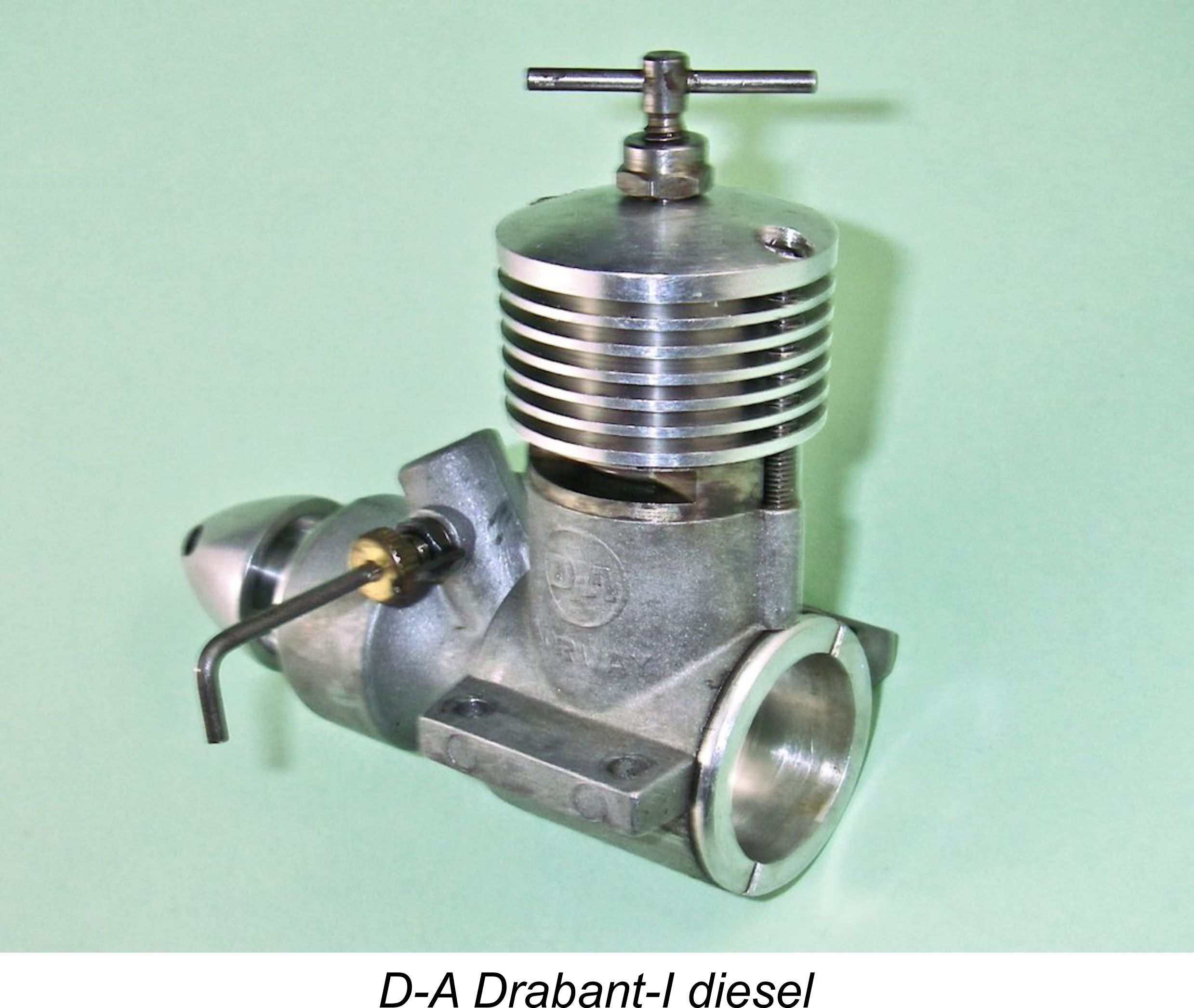 The standard of manufacture was very high – all fits and finished were outstanding. Claimed output for this engine was 0.30 BHP @ 14,000 rpm. Although this particular model was never the subject of a published test, in the English-language modelling media at least, this claim has a very honest ring to it. That said, the standard Drabant was clearly designed more for torque development than all-out top-end performance.
 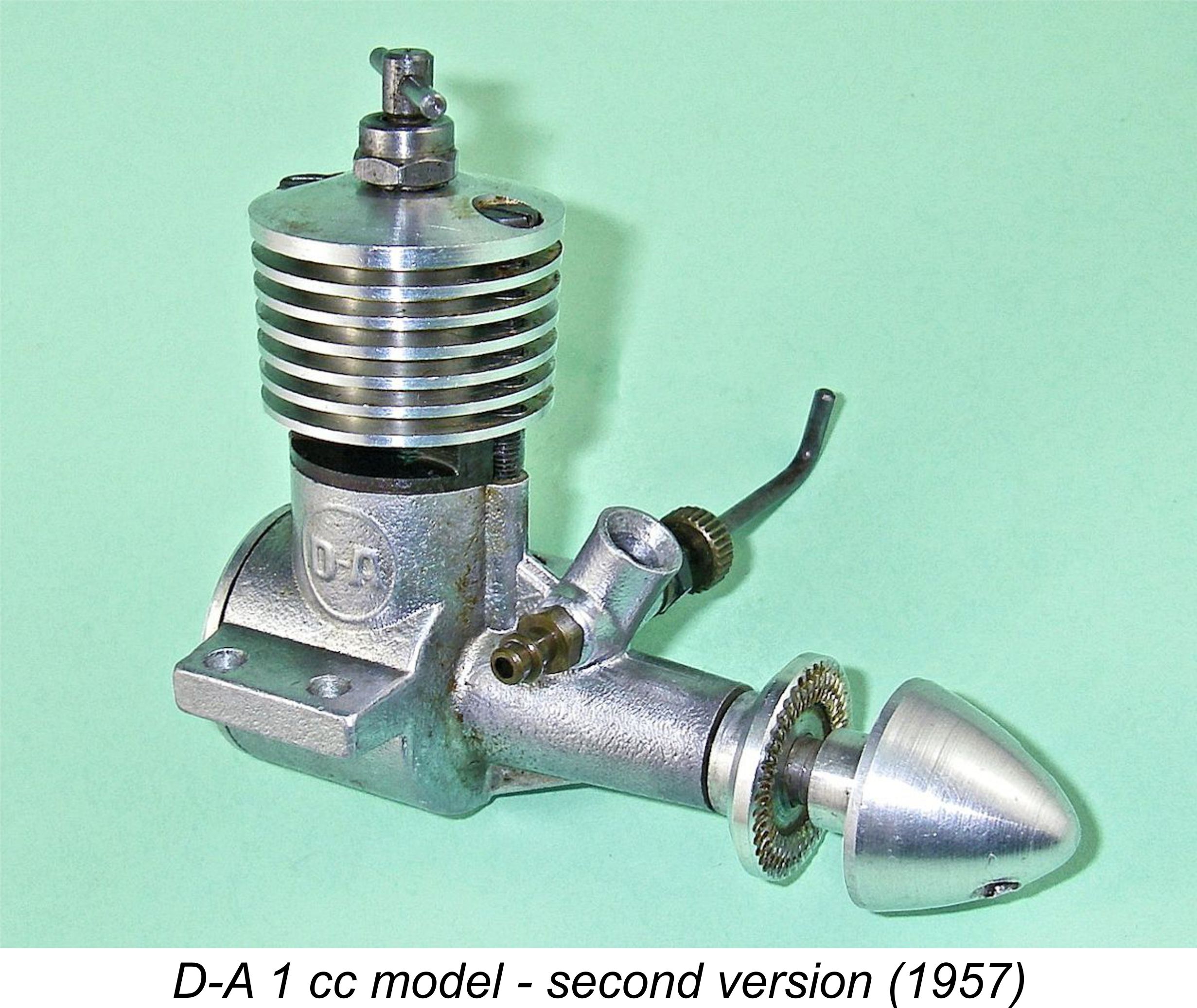 The new model which appeared in 1957 was constructed very much along the lines of the 2.47 cc Drabant described earlier. The screw-in cylinder assembly was supplanted by a two-screw attachment system exactly like that used in the Drabant, including the two vertical grooves in the cylinder port belt to engage with the two cylinder hold-down screws and thus ensure correct alignment. In addition, the very elegant gland nut arrangement for providing security of compression settings was carried over from the larger model. The needle valve assembly also followed the E.D. style design pattern of the Drabant, as did the aluminium alloy spinner nut.
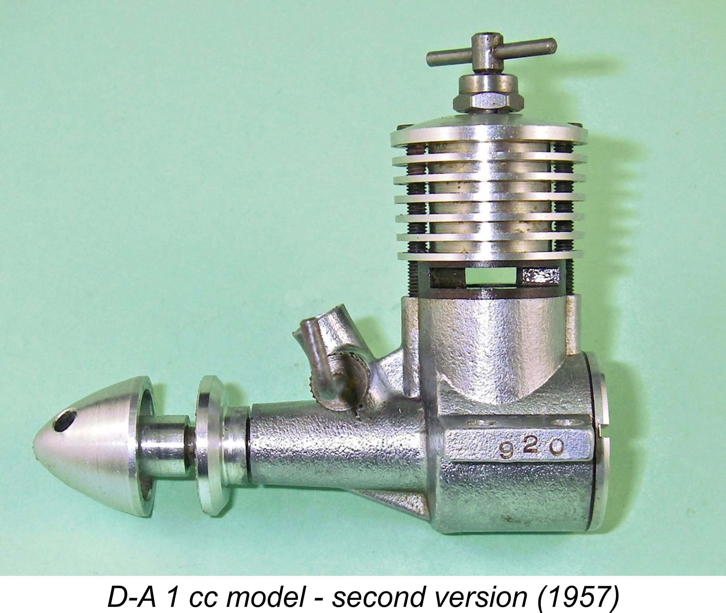 Unlike their original 1 cc predecessors, these engines carried serial numbers. The illustrated example bears the number 920 stamped into the outer end of the left-hand mounting lug. Bore and stroke remained unchanged at 11 mm apiece for a displacement of 1.04 cc (0.064 cuin.). The engine weighed in at a checked figure of 77 gm (2.71 ounces), a very small increase over the previous model’s 73 gm.
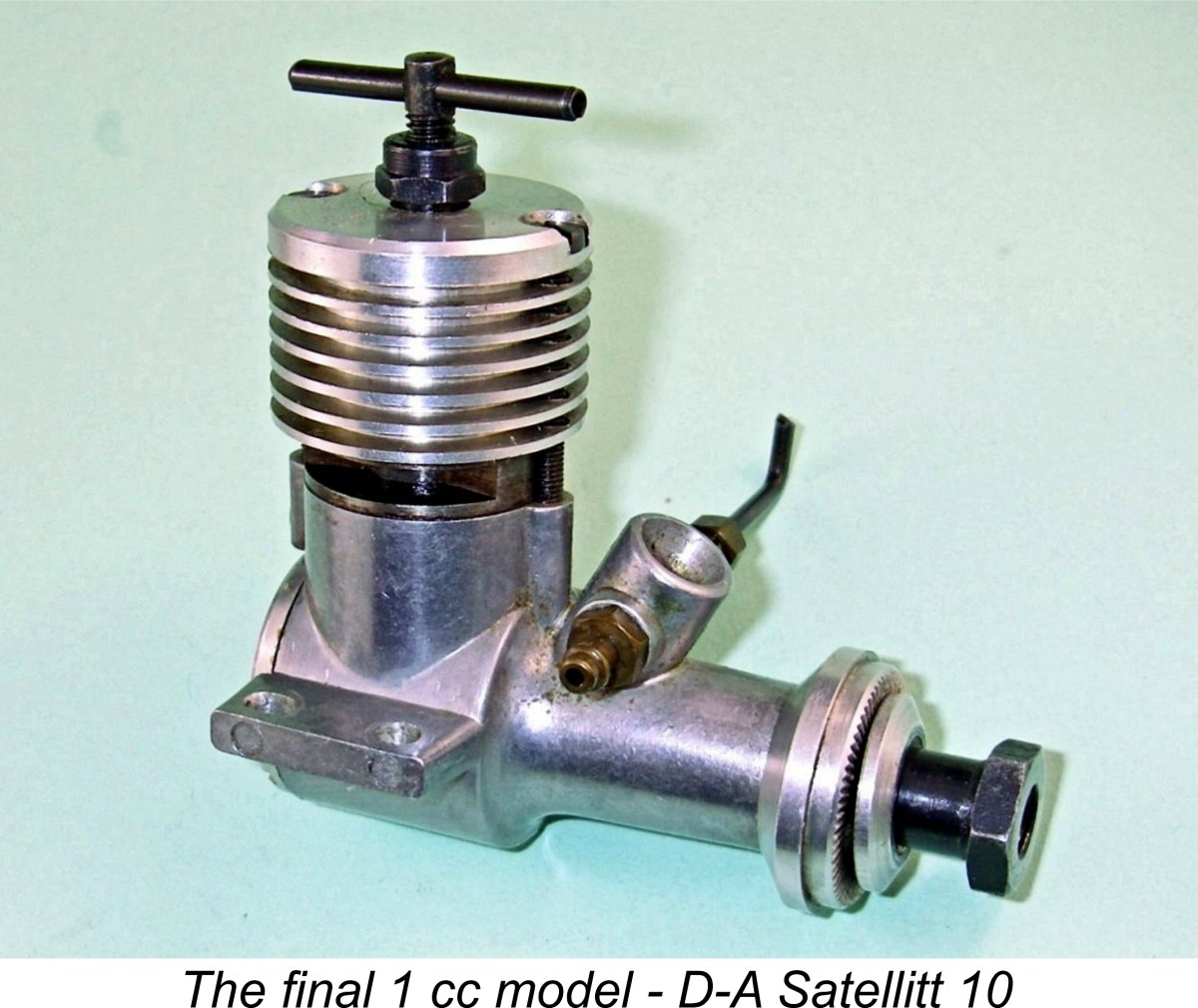
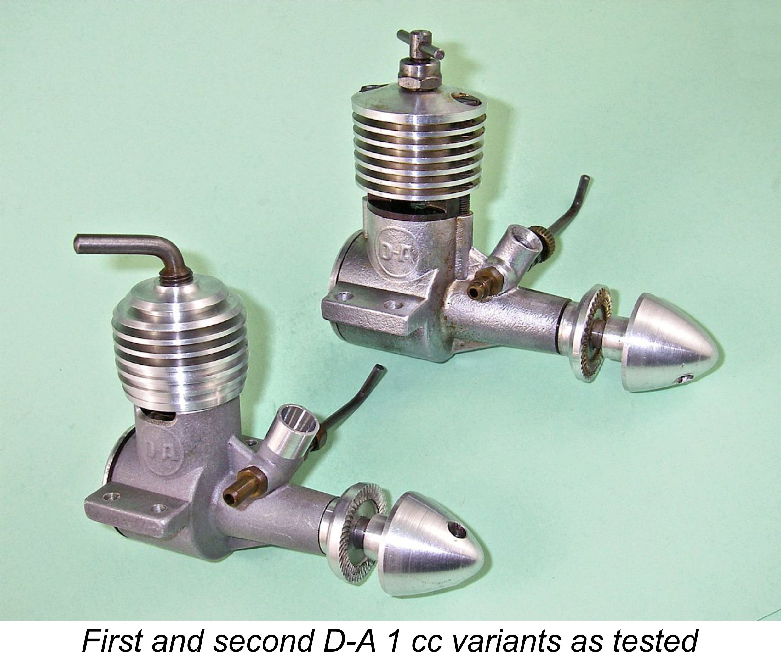 I saw no need to repeat Peter Chinn's full test of the first variant of the D-A 1 cc model. However, I did see value in undertaking a few spot-checks on the first and second models to see what effect, if any, the design changes discussed above might have had upon handling and performance.
 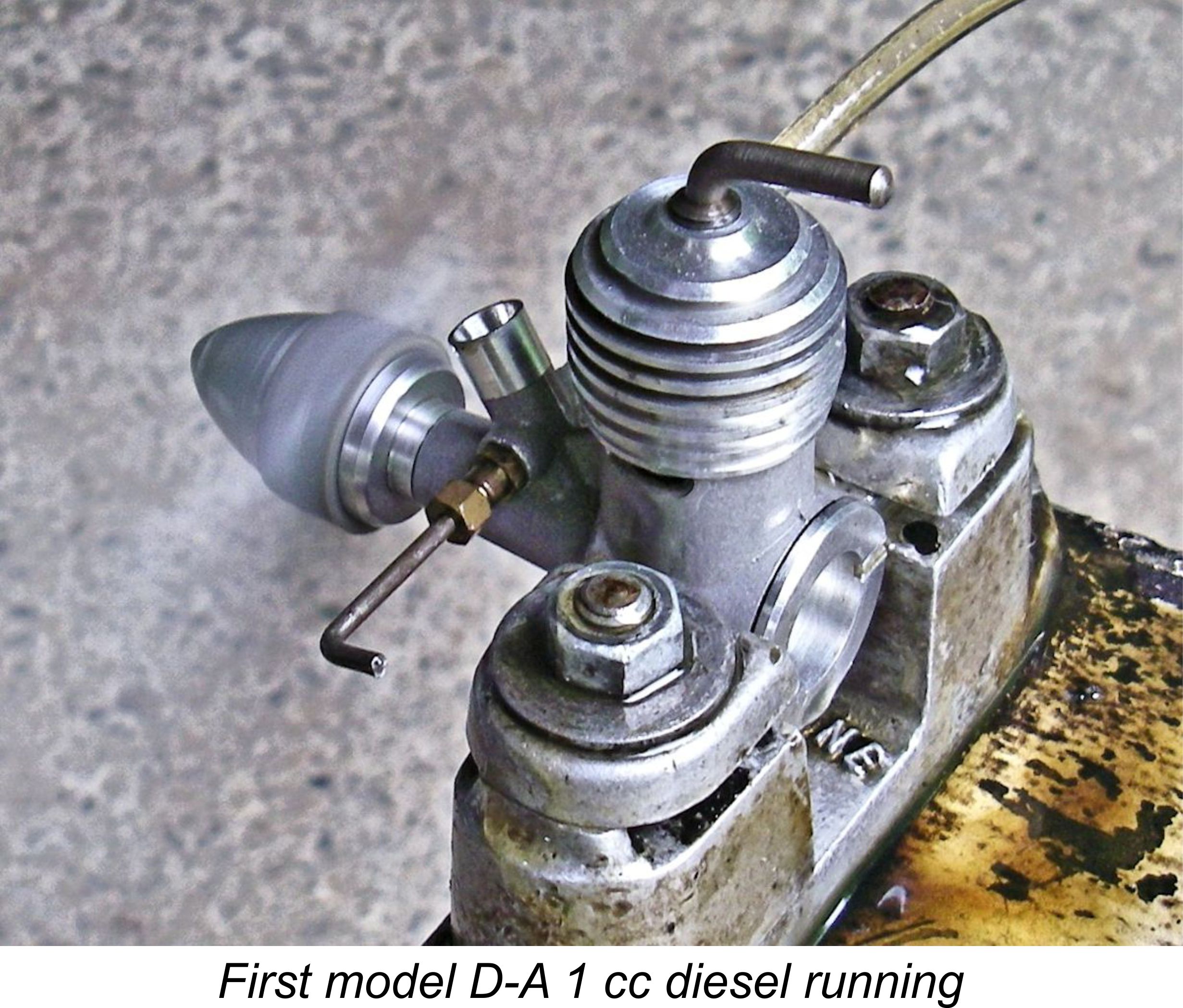 engines. This observation runs counter to Peter Chinn's comment that the first model of the D-A 1 cc diesel did not require a prime at any time. It's true that both engines will start from cold by choking alone, but there was a marked degree of hesitancy which was immediately relieved by a prime.
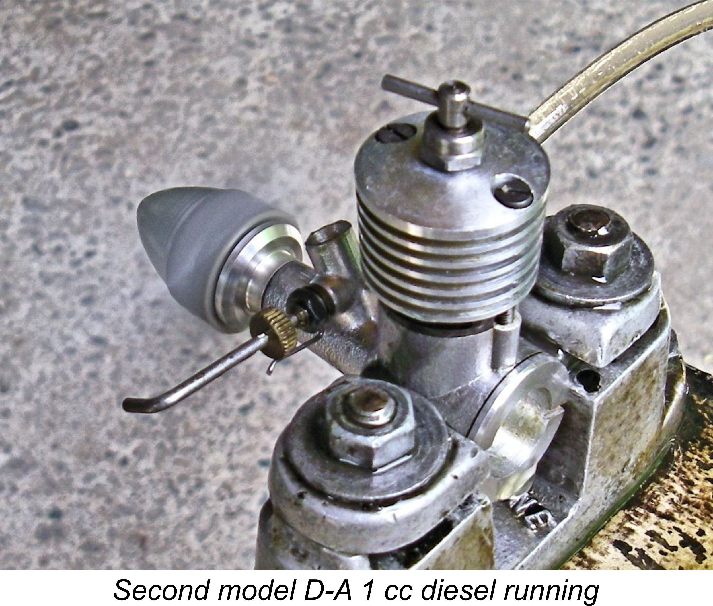 So how do the two designs compare? Well, the tested example of the first model actually out-performed the second model! It managed 11,600 rpm on an APC 7x4 - around 0.091 BHP at that speed. This of course is very consistent with the manufacturer's performance claim as well as being right in line with Peter Chinn's findings. However, the second model could only manage 11,400 rpm on the same prop - an output of approximately 0.087 BHP. A somewhat faster Cox 6x4 was turned at 13,100 and 12,700 rpm respectively for approximate outputs of 0.076 BHP and 0.069 BHP respectively. The peak for both motors almost certainly lay between these two figures, but I was unable to find a prop in my calibrated test set that fell in between these two so that I could "fill the gap". Seemingly I will have to create a few more custom props for my test set!
 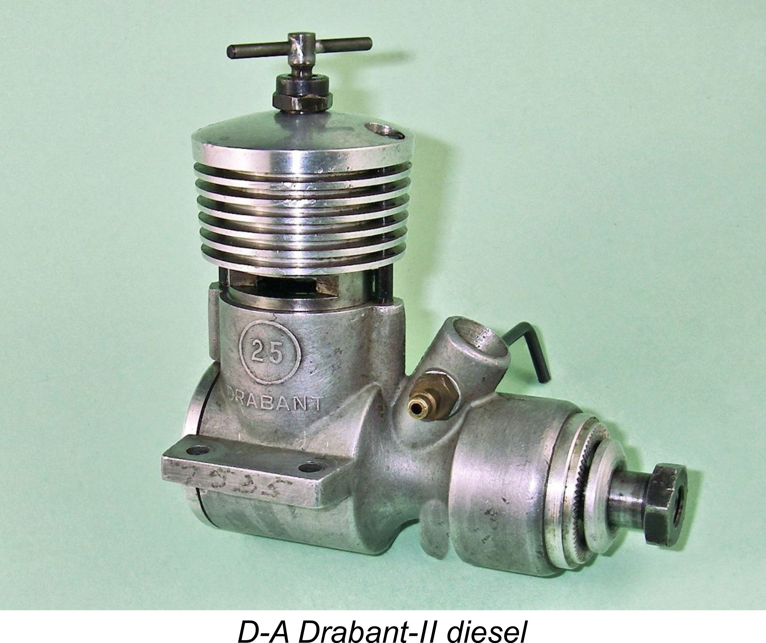 Despite this set-back, production of the Drabant continued, albeit with some significant modifications. It will be recalled that the original Drabant had a crankshaft journal diameter of 8 mm with a 5 mm internal gas passage, giving a rather marginal journal wall thickness of only 1.50 mm. Jan moved quickly to rectify the situation with the original version of the Drabant by reducing the diameter of the internal gas passage in the shafts fitted to later examples (or used as replacements for broken shafts in earlier examples) to only 4.5 mm, as measured from my previously-illustrated late example of this model (engine number 6593). Engines having serial numbers of 6000 or higher will generally be found to have the modified shaft, as will many lower-numbered engines for which replacement shafts were supplied under warranty.
 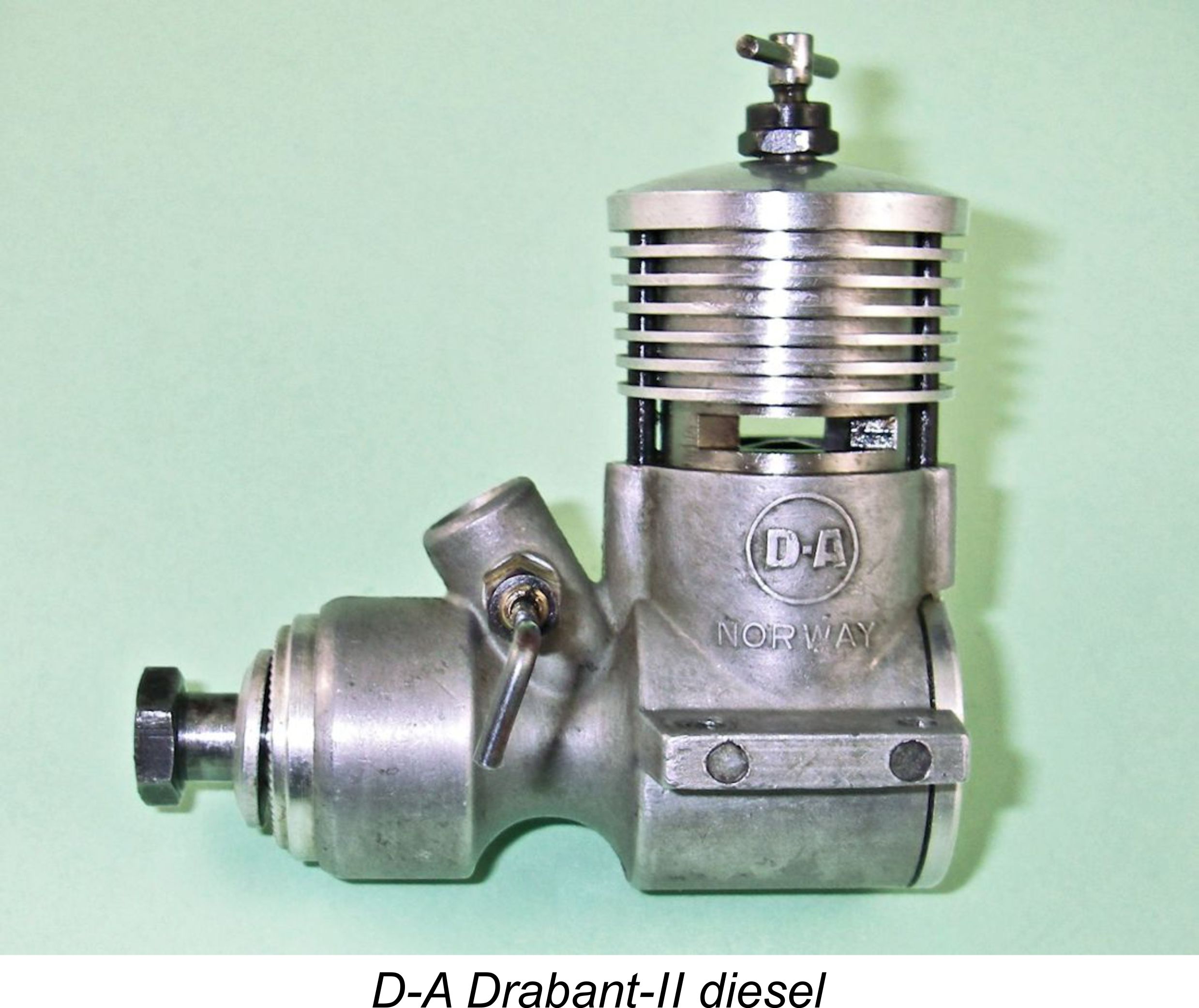 Advantage was taken of the increased shaft diameter to also increase the diameter of the internal gas passage from 4.5 mm back up to a measured 5.2 mm. As well as theoretically releasing a little more power, this left the larger-diameter crankshaft with a wall thickness of 2.17 mm as opposed to the 1.50 mm thickness of the original component and the 1.75 mm of the interim shaft. Spread around a larger diameter, this significantly increased the sectional area of metal available to resist operating stresses. Moreover, the improved material specification increased the shaft’s toughness considerably.
 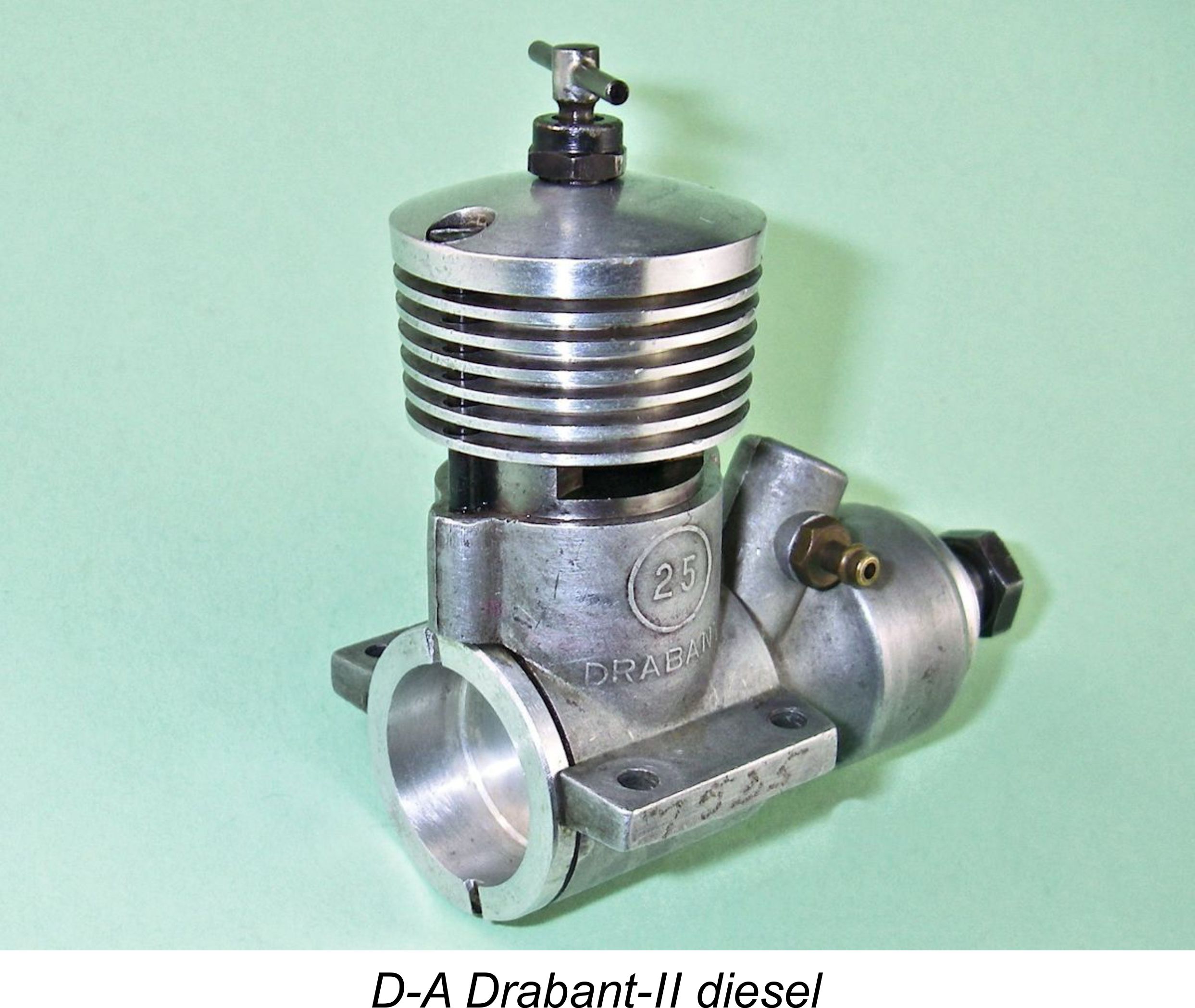 Thanks to the design measures noted above, weight was essentially unchanged at a checked 167 gm (5.89 ounces). Bore and stroke measurements likewise remained the same. The port timings of this variant also remained very much on the conservative side. According to Peter Chinn, the engine featured an exhaust period of 136 degrees to go along with a 120 degree transfer period. Induction timing was 75 degrees ABDC to 40 degrees ATDC for a total period of a relatively modest 145 degrees. My illustrated example of the Drabant-II also features a brief sub-piston induction period of some 30 degrees around top dead centre, although Chinn doesn't mention this in his test report on the engine (see below).
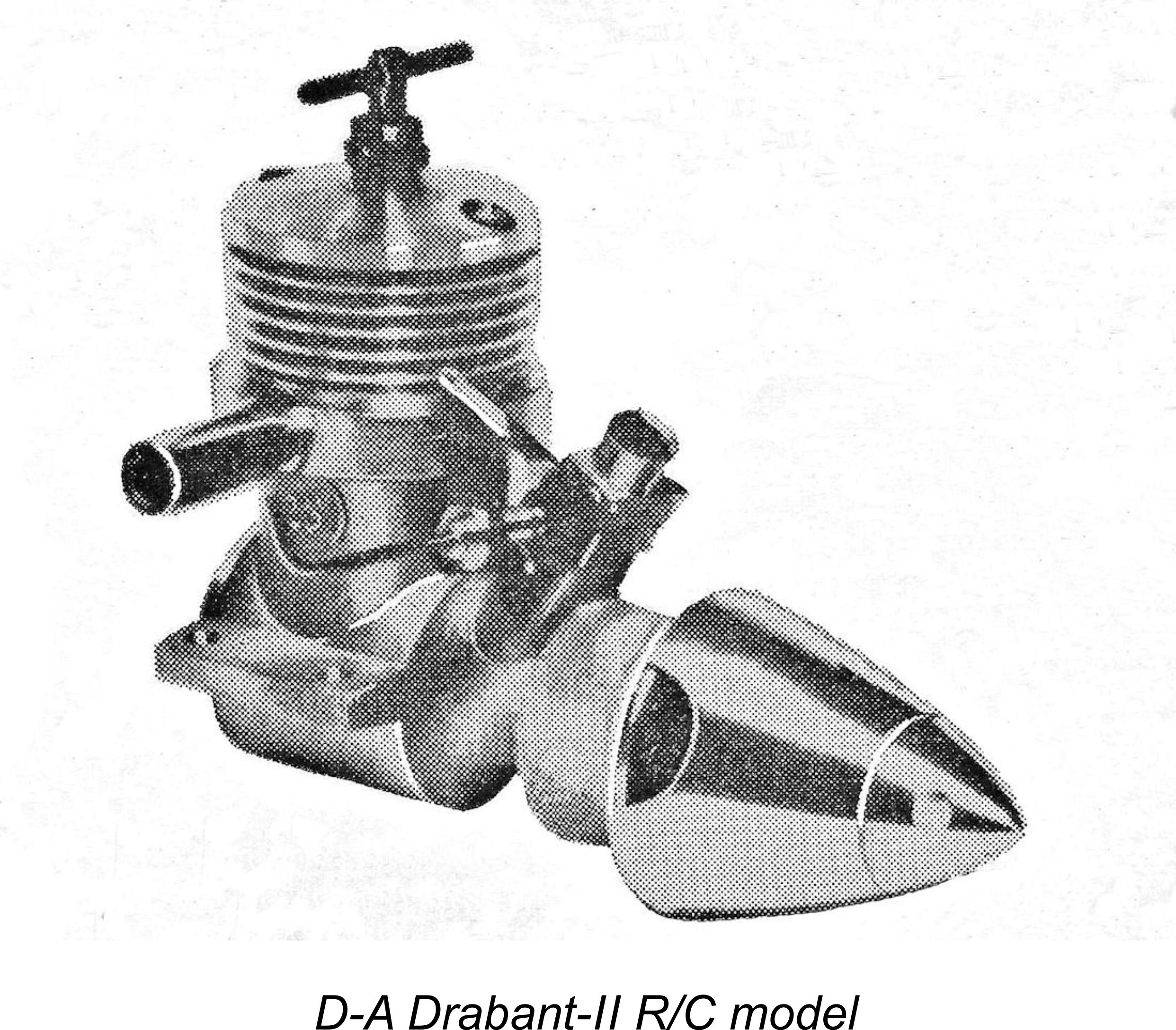
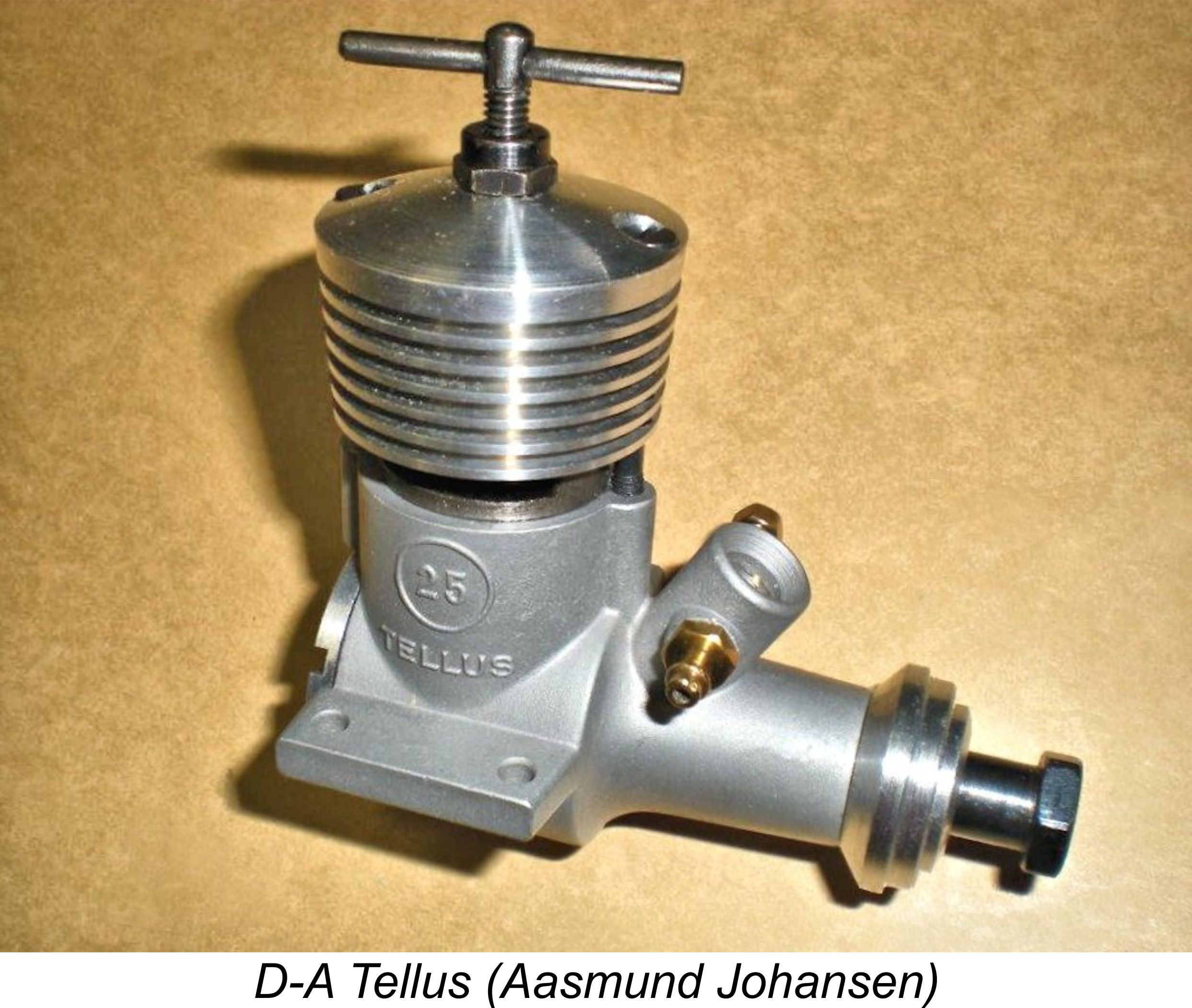
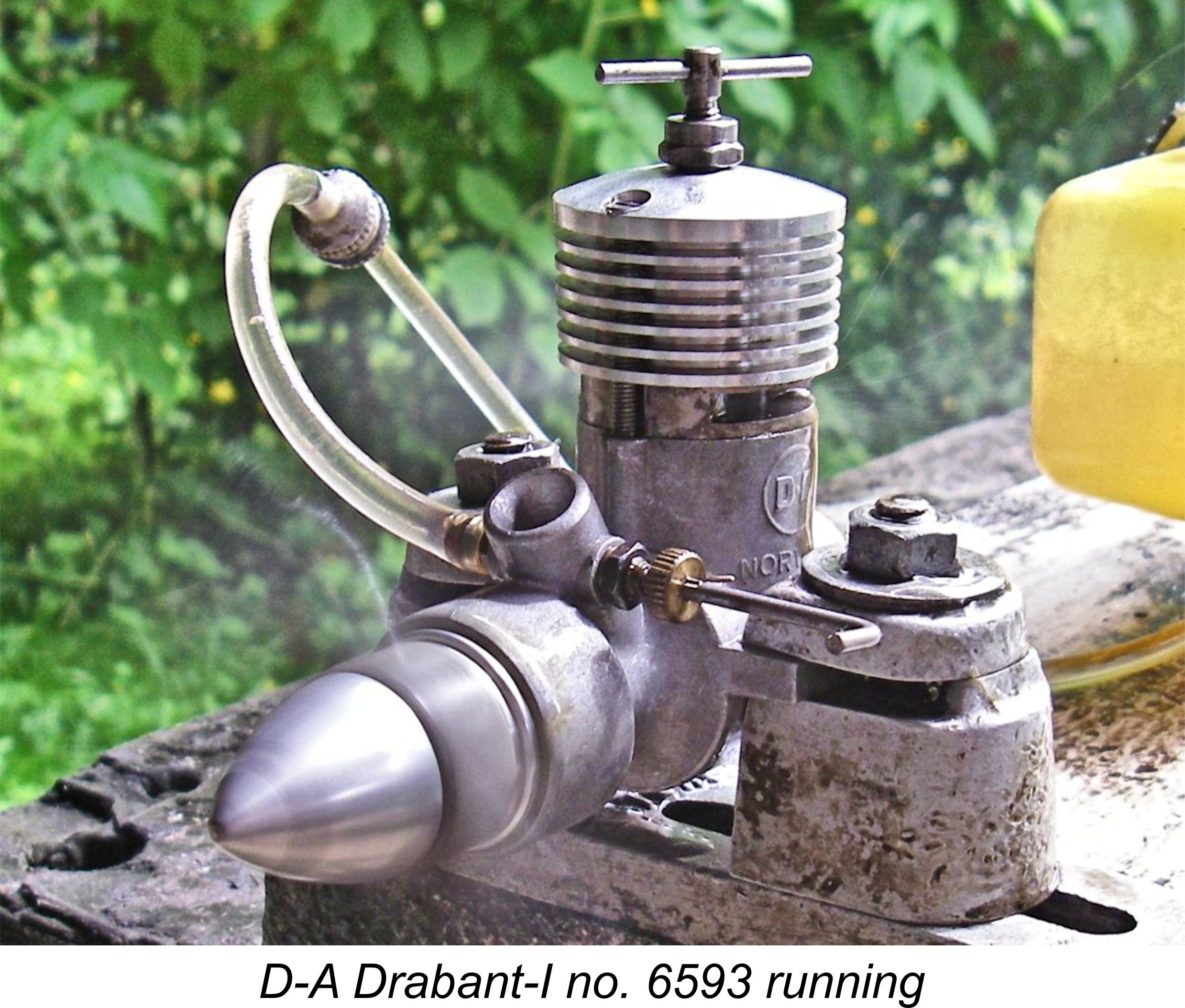 As previously noted, it appears that the original version of the D-A Drabant was never the subject of a published test in the English-language modelling media. I have run my own LNIB example of this engine, number 6593, finding it to be a very easy-starting, smooth and powerful performer. However, given the reported issues with the crankshaft, I have elected not to risk putting this example through the rigors of a full bench test, despite the fact that it is fitted with the interim crankshaft which featured a smaller central gas passage for increased strength. The manufacturer’s claim of 0.30 BHP @ 14,000 rpm must therefore stand unverified.
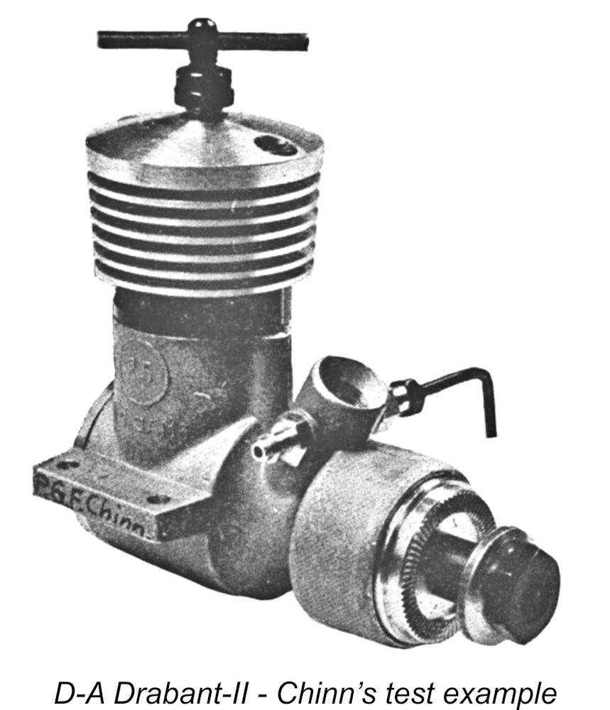
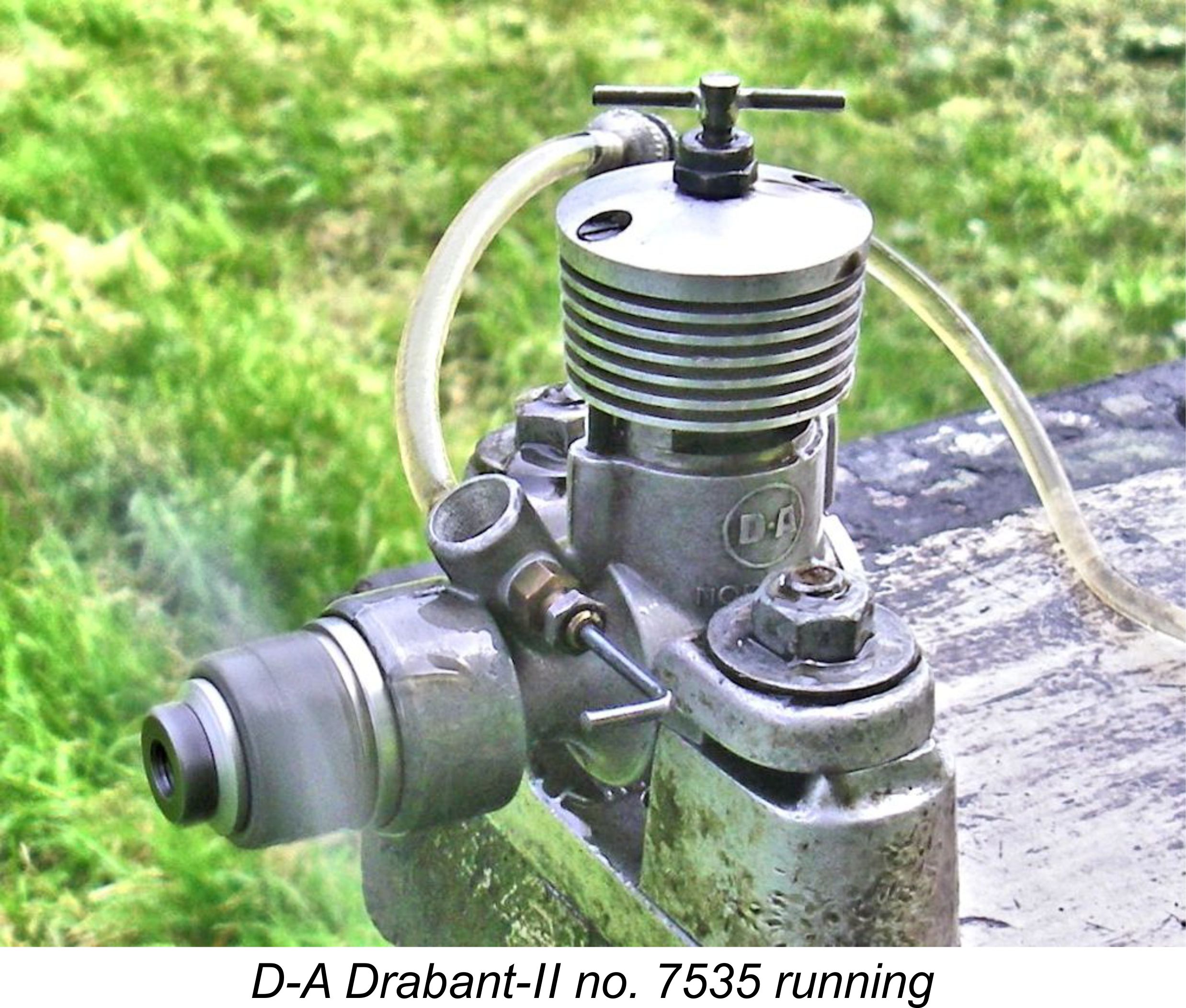 The Drabant-II proved its worth immediately by starting very easily indeed and running flawlessly. Response to both controls was very positive without being in the least bit critical, making it very easy to establish optimum settings. The one characteristic worth noting was the fact that the engine started most readily when cold on an exhaust prime. In this, it mirrored the characteristics noted earlier for the D-A 1 cc models. Although it would start on finger-choking alone, a prime was definitely the quick way to go. Hot restarts were immediate using finger-choking only.
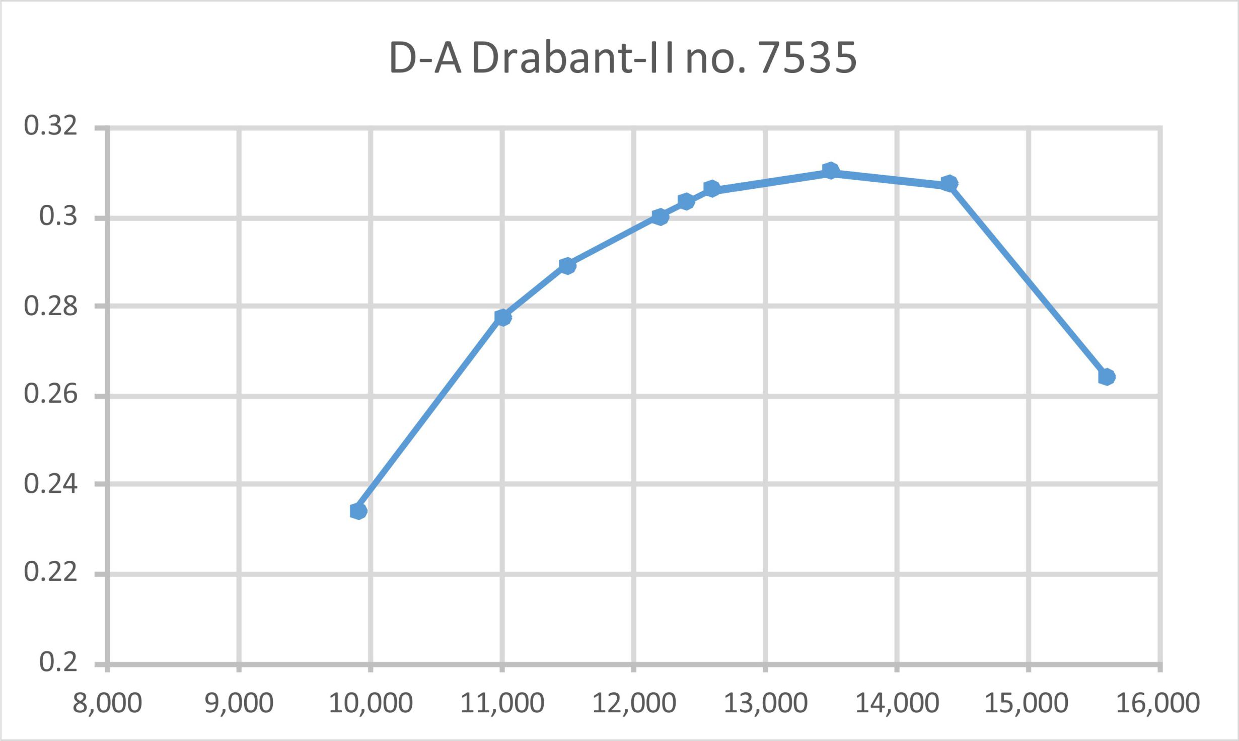
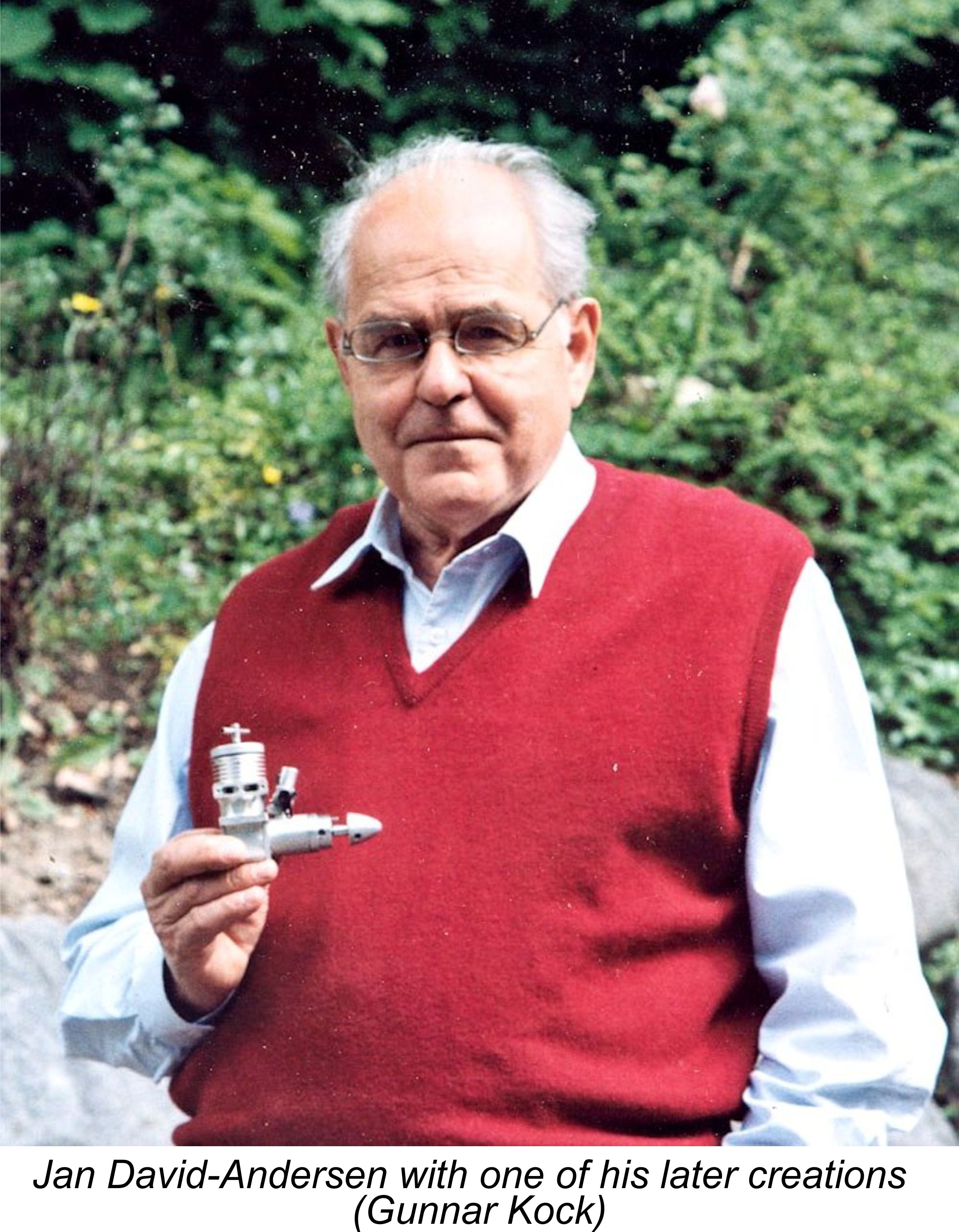 Despite the termination of series production of model engines, Jan remained a die-hard model engine enthusiast, returning to his roots by continuing to make small numbers of engines for his own enjoyment and that of his friends. Moreover, a comprehensive spare parts inventory for existing D-A engines was maintained – a fine example of responsible customer service. However, by 1972, when Bob Leisses first visited the David-Andersens in Norway, demand for spares had seemingly evaporated. At that time, the remaining parts were being assembled into complete engines and "autographed” with an electric engraving pencil by Jan Bue, the David-Andersens’ youngest son. These examples were not serialized. Some parts remained available for a little longer, but were all sold off by 1974.
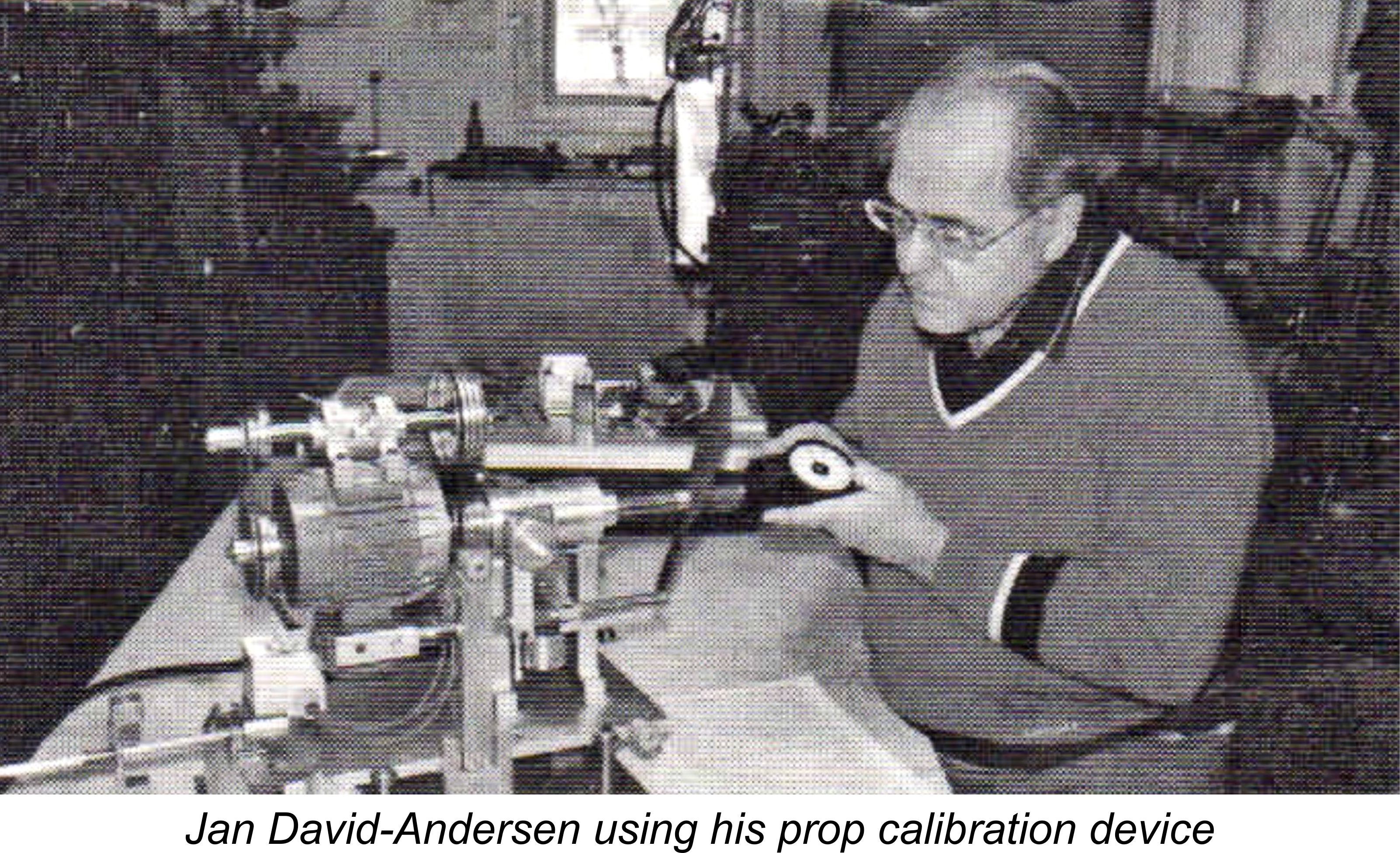 Another interesting development originating in Jan’s workshop was a superbly-constructed test rig for calibrating model airscrews in order to establish their power absorption coefficients. The use of calibrated airscrews has always been the most practicable and dependable method of establishing an engine’s performance, but it is completely dependent on assembling a set of test airscrews for which power absorption coefficients are reliably known. Jan’s device provided a dependable and reproducible means of establishing such figures. His rig was used in 1997 to calibrate the set of test airscrews used by “Aeromodeller” magazine testers in determining the outputs of engines on test.
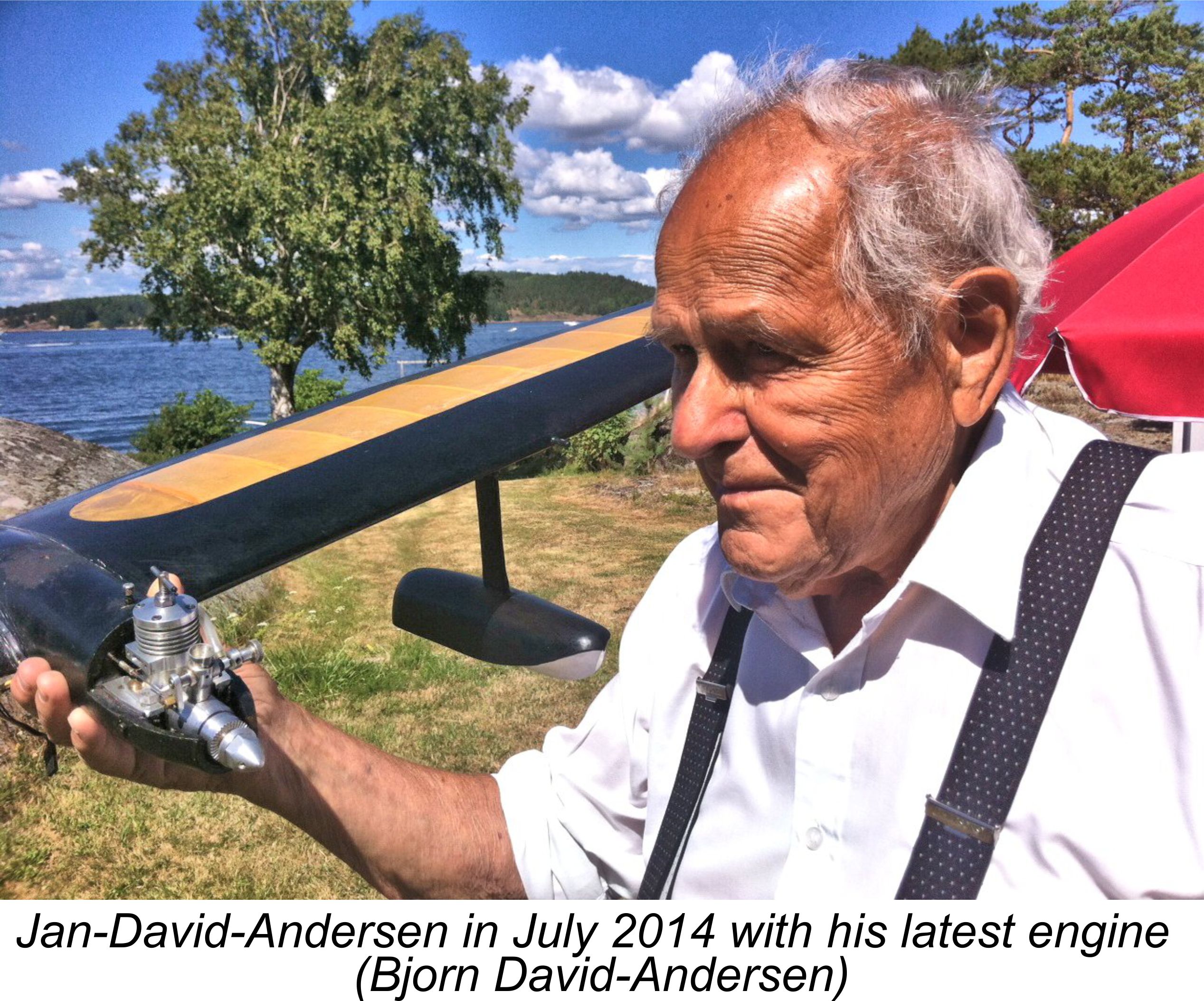 If a sufficiently large sample is compared, it’s possible over time to reach a pretty good estimate of the coefficients for one’s own test set of props. The critical thing then becomes to take very good care of those props and use the exact same props for all tests. It has taken the present author some years of experimentation and comparative testing to assemble a comprehensive set of test props which yield results which are consistently comparable with published figures.
 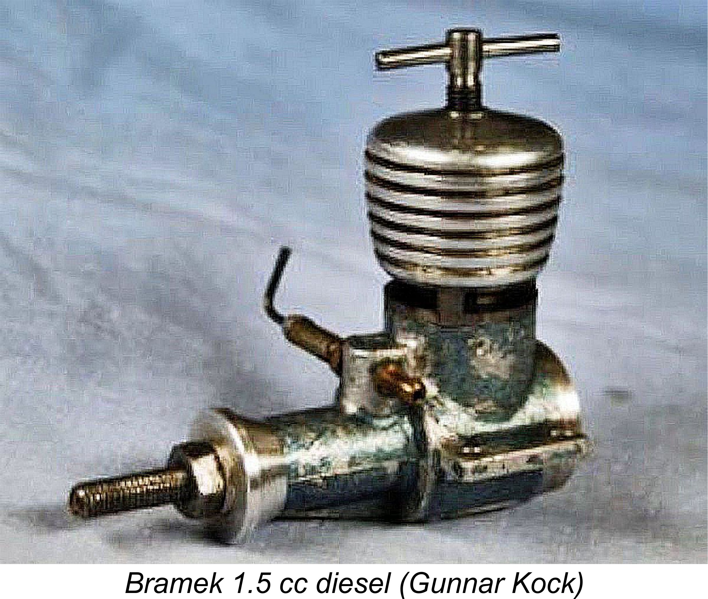 these - Øivind Andersen and Jan David-Andersen. For the sake of completeness, I'll briefly mention the “other” manufacturer here.
| |