
|
|
The Ken 61 Racing Engine
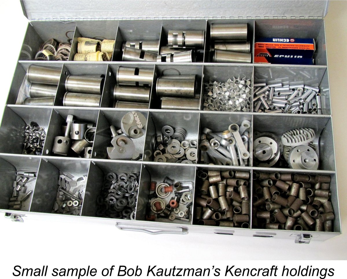
My own efforts to learn more about this fascinating powerplant were triggered by my fortunate acquisition of a nice example through eBay (oddly enough, serial number 2017, matching its year of acquisition!). As usual with me, this immediately initiated a search for authoritative information regarding the engine’s history. What’s the point of collecting items about which you know nothing?!? That’s the entire motivation behind this website - to maintain interest in collectible model engines by ensuring that authoritative information about them is readily available. If there were no catalogues, there would be no stamp collectors! When dealing with any American model engine, my first port of call was invariably my late good friend and unrivalled American model engine guru Tim Dannels of Buena Vista, Colorado, USA, who over the years Bob was undoubtedly the world’s leading authority on the Ken engines, having acquired the residue of the entire Ken project some years ago along with a number of related items collected over time from other sources. We are all immensely indebted to Bob and Tim for the preservation of information on this unique powerplant. I hereby freely acknowledge having drawn heavily upon the cited information sources, with my grateful thanks. When I began researching this article in early 2017, Bob was offering the entire Ken project for sale at what I considered to be a quite reasonable price. Bob's holdings were very comprehensive, including parts, castings, dies and tooling. Bob later confirmed that these materials were eventually acquired from him by an unnamed buyer. I have no idea where they are today.
There was also some discussion of the engine in a thread which appeared on the R/C Groups forum in 2015. This included some very pertinent comments by my late and greatly-missed mate David Owen, along with a number of fine images of the engine. More of David’s comments in due course. Nice to be working with you again, mate! Now, having summarized my sources, it’s time to get on with the telling of the tale……….. Background and Early Days
The actual designer/manufacturer of the Kencraft range was a gentleman named Ken Wade. Bob Kautzman tells us that Wade was a teacher at the Garden Grove High School, where he taught woodworking and auto maintenance. He was evidently also a model enthusiast and a skilled model engineer. It’s not known when Ken Wade first started experimenting with building his own model engines, but it was almost certainly during the period prior to America’s December 1941 entry into WW2. It appears that Wade had previously been a model power boat enthusiast who had built a number of engines for his own use in that field. Unfortunately, the dates and designs of these early prototypes are unknown.
Production of the Ken 61 began in mid 1945 more or less concurrently with the conclusion of WW2, making it the first all-new racing engine to appear in America in the post-war era. The timing of this advertisement clearly proves that Ken Wade had completed the design work and prototype testing along with the dies and production tooling while WW2 was still raging in the Pacific theatre. This timing may come as a surprise to some readers, but in fact the commercial production of model engines in the USA had resumed in around September 1944 following a decision by the US War Production Board to release sufficient material for non-military purposes to allow this to happen. All of the initial late wartime productions which hit the market beginning in late 1944 were pre-war designs for which the dies and tooling already existed from pre-war days. An article on this resumption appeared in the October 1944 issue of “Air Trails Pictorial” under the title “Engines Return!”. Presumably it was this change in official policy which allowed Ken Wade to contemplate initiating the manufacture of his own design while the war was still ongoing. The image of the Ken 61 included in the initial advertisement of August 1945 was in effect an “artist’s impression”, implying that no complete examples were available for photography at the time when the advertisement was laid out, presumably no later than early July 1945 to meet the editorial deadline for the August issue of the magazine. Subsequent advertisements featured a photograph of the actual engine. The November 1945 ”Model Airplane News” advertisement which is reproduced here is typical.
However, the engine was advertised as being suitable for “planes, cars and boats”. The photographic image included in the later advertisements showed the engine set up for aero service. Apart from his previously-noted interest in boats and cars, Ken Wade also developed an early interest in the emerging field of control-line flying, thus having a foot in all three camps. Having set the stage and seen the Ken 61 enter production, let’s now take a close look at this very innovative design. The Ken 61 - Description
The engine was built around a quite complex main casting formed in aluminium alloy using a permanent steel die which was charged by gravity. A small sand core was evidently used to create the bypass bulge on the transfer side. The backplate was cast integrally with the main crankcase, as were the bypass passage, the exhaust stack and the upper cylinder jacket. The engine was topped with a finned cast alloy cylinder head having a centrally-located plug. A separate bolt-on cast aluminium alloy front housing was employed. Like almost all racing engines of its day, the Ken 61 used cross-flow loop scavenging with a baffle piston. A However, no fewer than three distinct piston configurations have been documented, all of which operated in the same cylinder liner having bridged ports. Two of these piston variants were machined from cast iron and featured a blade baffle. Some of these are lapped into their bores, but others feature two rings. A ringed cast-iron piston is a new one on me - the arrangement seems to negate the usual reason for using rings, which is to allow the piston to be made far lighter through the use of a light alloy casting. Presumably the motivation in this instance was to side-step the lapping process. My own recently-acquired engine is one of the twin-ring cast iron piston models, as is the example owned by reader Ken Smith. The seal provided by the rings is outstanding - my example feels almost like a lapped engine when turned over. I also own two incomplete "bones" engines, both of which have well-fitted ringless lapped cast iron pistons.
In all variants, access to the bypass passage was enhanced through the use of two circular ports in the lower piston skirt which registered with similar openings in the lower cylinder wall. This arrangement was identical to that employed in the highly influential Hornet 60. Apart from the improved bypass access, it also enhanced piston cooling. In all cases, the wrist pin was a tubular steel component having brass end pads. The piston drove the crankpin through an aluminium alloy con-rod which was cast from a permanent mold and featured bronze bushings at both ends. If my example may be taken as typical, cylinder port timing of the engine was fairly conventional. The exhaust port opened at 115 degrees after top dead centre (ATDC), while the transfer port opened some 10 degrees later at 125 degrees ATDC. Exhaust and transfer periods were thus 150 degrees and 130 degrees respectively - quite reasonable figures. So far, it all sounds perfectly familiar, doesn’t it? Why all the earlier talk of innovation?!? Well, this is where the familiarity ends! What really set this engine well apart from all of its contemporaries was its induction system, which is unique in my personal experience. Read on …………
The result was one of the most interesting and innovative induction arrangements ever to emerge from a model engine manufacturer anywhere at any time. At first sight the Ken 61 looked like a conventional FRV design. However, nothing could be further from the truth! In reality, the engine featured not one but two remarkable innovations - a front rotary disc (FRD) valve allied to a crankcase turbocharging set-up. Wade called this combination the “Turbo Valve” induction system. This feature became one of the engine’s major selling points. It’s well worth spending the time required to describe this fascinating and very clever system in some detail. Please bear with me, because this is rather complex stuff which is difficult to describe in mere words! This being the case, I hope that the attached images will help to make the arrangement clear. The reader should remain mindful of the fact that the term “Turbo Valve System” included both the turbo fan and the front disc valve induction arrangement.
The rear ball-race was located forward of the usual rear race position, being axially retained there by a thin shoulder of residual material which was left between the rear outer ball race and the front face of the crank disc. This shoulder defined the location of the rear ball-race by limiting its rearward movement – the opposite of the usual arrangement in which the rear ball race was inserted from the rear and had its forward movement limited by the front housing. The shoulder also created a gap between the rear ball race and the front of the crankweb which would not be there in a conventional design.
So far so good, but the entry of mixture into the crankcase had to be appropriately timed. This was accomplished by having the front face of the crank disc operate in intimate proximity to the rear face of the front housing. The crank disc incorporated a large streamlined cutaway which acted exactly like a disc rotary valve by opening and closing the rear exit points of the two induction channels at the appropriate times. So this was in fact a disc valve engine with the disc (which doubled as the crank disc) at the front rather than at the rear!
Pretty interesting stuff, eh?!? But there was more ………. much more! The engine was provided with a stamped sheet metal aluminium alloy fan having almost the same outside diameter as the outer ball races so that it just cleared the internal surface of the bore in the housing. This fan was located on the crankshaft immediately rearward of the lower exit of the downdraft intake venturi, which was of course open to the atmosphere at all times. The fan was driven at crankshaft speed purely by friction created by the pressure between two tubular spacers which positioned it correctly and were a close sliding fit around the main shaft between the ball races. In theory, the rotation of this fan would have the effect of internally pressurizing the rear half of the front housing. When the disc valve was open, this pressure would act in concert with the internal vacuum created by the rising piston to force vaporised fuel mixture through the two passages around the rear ball-race and through the cut-away in the crank disc into the main crankcase. In effect, this was an "8,000 +" RPM crankcase supercharging system! The theoretical induction benefits of this system are readily apparent, as are both the excellent fuel atomisation which it would promote and the very effective rear ball race lubrication which it would ensure. However, the obvious downside is equally apparent – a somewhat convoluted gas passage from the intake to the crankcase. In all honesty, it seems to me to be an open question whether or not any benefit accruing from the turbo fan would be offset by the relatively restrictive gas pathway through which the fan had to push the mixture. Indeed, the efficiency of this very simplistic arrangement seems very much open to question. Ingenious, though!
Setting aside such considerations, it will be appreciated that for the system to work at all with or without the fan it was necessary to maintain a very close clearance between the front face of the crank disc and the rear face of the main bearing housing, since the engine’s base compression would depend upon this clearance being minimal and hence essentially gas-tight. It was also necessary to maintain some axial pressure between the two tubular spacers which both located and drove the turbo fan.
When compressed, this spring washer applied a forward pressure to the rear ball race and a matching rearward pressure against the crank disc. I'm extremely grateful to Bob Kautzmann for providing a replacement 5/16 in. Thackeray washer for my own engine, which turned out to have an incorrect component fitted. To maintain the tension in the Thackeray washer, a sleeve nut was positioned on the threaded outer end of the crankshaft. This nut bore against the front inner race, thus limiting the rearward movement of the shaft in the ball races which the tension exerted by the compressed Thackeray washer would otherwise tend to cause. The main crankshaft journal was an easy sliding fit inside the inner races, making such a restraint very necessary. It should be clear that the rearward pressure applied by this sleeve nut would have to balance the forward pressure applied by the compressed Thackeray washer at the rear. This would have the effect of placing the entire ball race/spacer/fan assembly under an axial compressive force at all times. This was of course necessary in order to maintain the friction between the two spacers which was necessary to drive the turbo fan. A lock nut was used to keep the sleeve nut in place during operation. Naturally, the forward thrust of the Thackeray washer upon the rear ball race had to be balanced by an equal rearward thrust against the front face of the crank disc, thus placing the main crankshaft journal under tension which was of course resisted by the pressure of the sleeve nut upon the front ball race. The If you’ve managed to follow all of this complexity, it must surely be obvious that the correct adjustment of this very intricate set-up was of paramount importance. The clearance between the front face of the crank disc and the rear face of the front housing had to be both sufficiently close to maintain an adequate gas seal and yet loose enough to avoid any excess build-up of friction losses. It would also require periodic adjustment to take up any wear which might result from the engine’s ongoing operation. A tall order! However, the system just described included provisions for a very simple procedure for setting and maintaining the system clearance to very precise limits. Hopefully the attached illustration and accompanying text extracted from the instruction manual will help to clarify the procedure. However, it’s necessary to point out that this illustration inexplicably does not include the Thackeray washer. Given its key role in the construction and operation of the system, this is by no means a trivial oversight, especially if an owner were to dismantle the front end completely for any reason (not recommended unless absolutely necessary!). The washer should have been shown mounted on the shaft between the front face of the crank disc and the rear face of the rear inner ball race.
Although not specifically noted in the manufacturer's instructions, the first step was clearly to remove the front housing from the engine. This step was necessary both in order to free the crankshaft assembly from any frictional inputs other than its own and to permit post-adjustment visual inspection of the system. One then removed the timer and prop driver/cam unit (which was kept in correct angular alignment using a Woodruff key). Do not lose that Woodruff key!! The next task was to slacken off the 3/8 in. lock-nut which secured the 7/16 in. sleeve nut located immediately in front of the forward ball race as noted earlier. This sleeve nut was the actual adjusting nut – the lock-nut was there simply to retain the correct setting. Space requirements dictated the use of a very thin ring spanner for the 7/16 in. sleeve nut – as Charlie Bruce pointed out, it might be necessary to grind down a dedicated wrench specifically for this purpose. The next step was to tighten the adjusting sleeve nut very slowly and progressively while holding the exposed crankweb to prevent the shaft from turning. If you’ve been able to follow the preceding description of the system, it should be appreciated that the effect of doing this was to compress the Thackeray washer by pulling the crankshaft forward in the ball-races, moving the crank disc towards the rear face of the front housing. The resulting compression of the Thackeray washer also increased the axial compressive force within the overall ball race/spacer assembly. It was of course this force which created the friction between the two tubular spacers necessary to drive the turbo fan. One was directed to continue to tighten the adjusting sleeve nut until a perceptible amount of drag was first felt in the system when turned over by hand. This drag was of course caused by the Thackeray washer having been compressed sufficiently to allow the onset of direct contact between the front face of the crank disc and the rear face of the front housing. It’s really unfortunate that the instructions did not make this clear. After that, the rest was simple. One was directed to slacken off the adjusting nut by 1/12 of a turn from the point at which the drag first became perceptible, then hold the adjusting nut in position relative to the crankshaft while tightening the lock nut securely. A tap on the outer end of the shaft to settle the components down and ensure that the rear ball-race was firmly seated against its locating shoulder left the system perfectly adjusted with very little drag and a more than adequate seal. All very ingenious indeed! After completing the above procedure, the owner was directed to visually inspect the clearance between the front of the crank disc and the rear of the main bearing housing. At the correct setting, the instructions specified that there should be no visible clearance between these two components. Given the engine’s dependence upon a gas-tight seal at this interface, this requirement is surely obvious.
In closing this discussion of the unique induction arrangements displayed in the design of the Ken 61, it's worth noting the fact that the concept of a front rotary disc valve was not in fact new - the noted English designer Edgar T. Westbury had utilized this same principle in his 5 cc Kestrel model way back in 1937. It's quite possible that Ken Wade got the idea for this design approach from an examination of a Kestrel, since it's known that a number of those engines did appear in pre-WW2 America. The front disc valve principle was also used by the Italian manufacturer Uberto Travalgi in his Atomatic diesels of 1945 - 1948. It's unlikely that the Atomatic designs influenced Ken Wade's thinking in any way - the timing is wrong. Be that as it may, the concept was later reprised by Willi Otto of East Germany in the design of his Wilo 2.5 cc diesel of the early 1950's. However, Ken Wade's combination of a front rotary disc valve and a turbo fan remains unique as far as I'm aware.
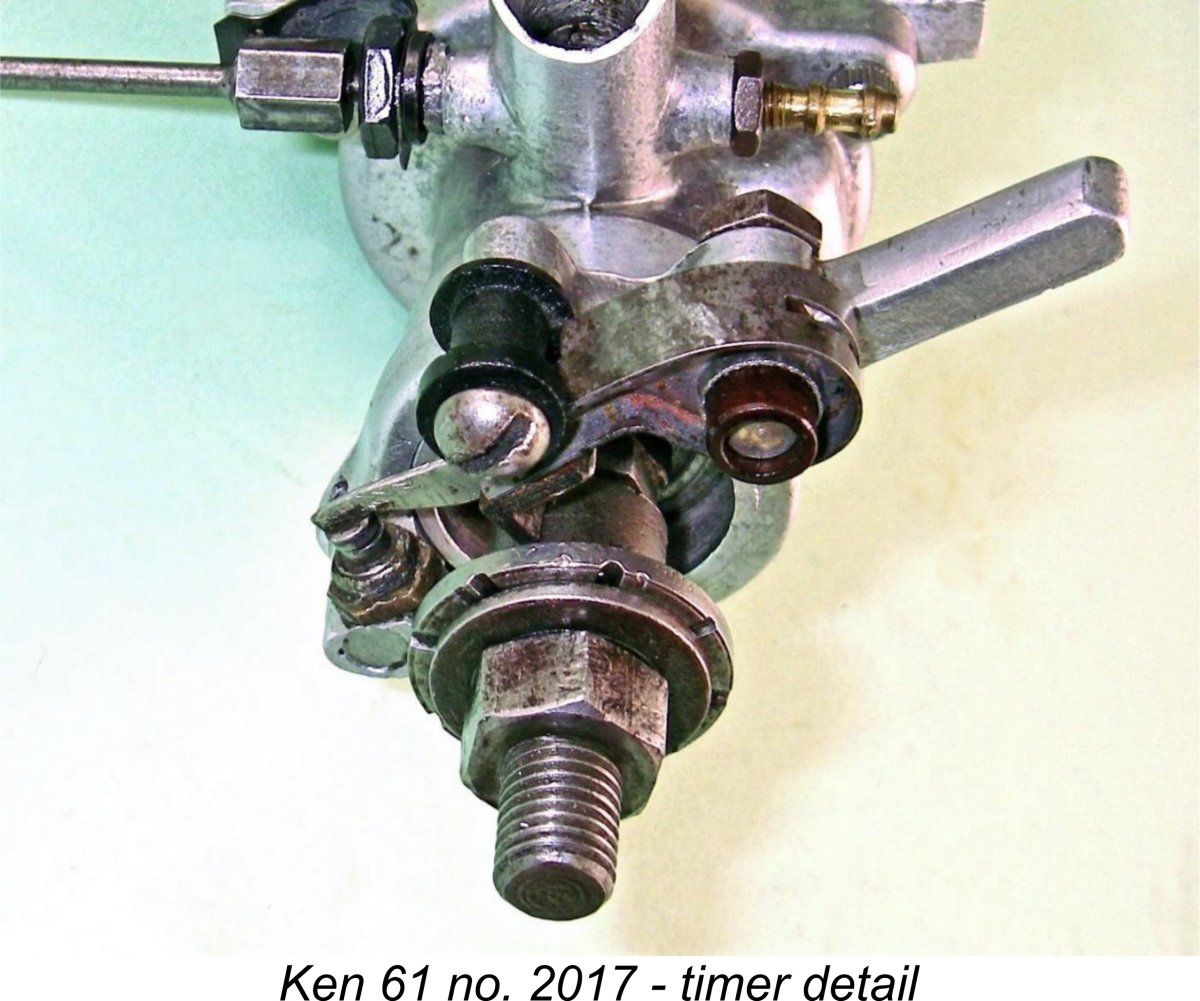
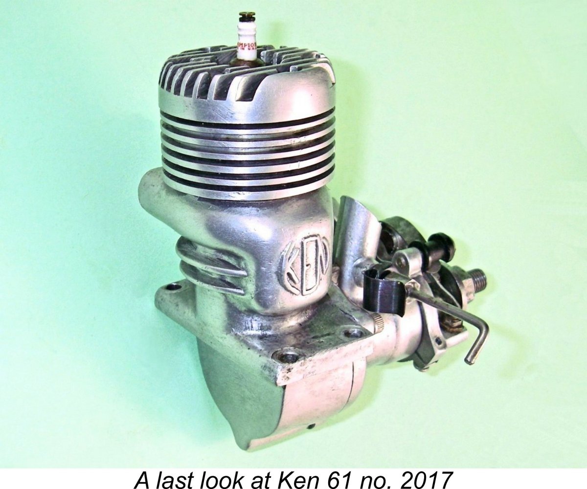
Two styles of timer were utilized. The earliest engines featured a two-piece timer having two arms, one on each side. An engine featuring such a timer appears above as the first illustration in this section of the present article. The later and far more common timer was constructed using a single casting with only one arm. The illustrated timer from my own engine number 2017 is one of these latter types. The entire engine was assembled using high-quality Allen-head screws – a really professional touch. Indeed, the general comment may be made that the Ken 61 was built to very high standards of quality throughout. Of course, it had to be in order to function at all.
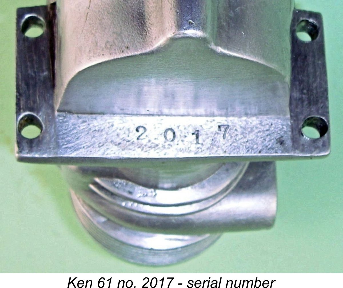
The numbers go up to just past 2000, suggesting that the total number of engines produced was a little over 1000. My initially-acquired unit which is illustrated here bears the number 2017, hence being a very late example. The highest serial number so far reported is 2086 (see below). Having spent so much time getting to grips with the Ken 61’s design complexities, I’m sure the reader is now asking the very fundamental question – all very interesting, but how does it run?!? Let’s see what we can do to answer that question. Performance
As usual, David tested the repaired engine himself. While agreeing that it was an impressive looking unit with its polished castings and complex induction system, David reported that on test it was found to vibrate excessively if pushed over 9,000 RPM, being no better in this regard than the notorious OK Super 60. This makes it appear highly unlikely that the engine could be successfully operated at the claimed peaking speed of 14,000 RPM. Although the unit tested by David was in good mechanical condition, he considered that example to be certainly less powerful than an Orwick or an Anderson of comparable displacement.
Mind you, that’s a fair amount of torque on display! If those props were APC items of similar sizes, the implied outputs would be in the neighbourhood of 0.570 BHP and 0.590 BHP respectively. I have no idea how the power absorption characteristics of the Rev-Up props compare with those for the APC series, but it would appear that the claimed power output may not be greatly exaggerated – only the speed at which the peak was attained. The engine would appear to be a pretty fair torque-producer at non-racing speeds. Overall, the above comments reinforce my previously-expressed doubts that the turbo fan contributed anything other than complexity to the design. Its main function appears to have been to legitimize the Even if the Ken 61 had in fact been competitive by mid 1945 standards, this happy situation would not have lasted long. The 1941 Hornet 60, for example, had managed only 0.55 BHP @ 15,500 RPM, putting the Ken well in the hunt on the basis of its claimed performance. Fair enough, but by mid 1946 the Hornet’s output had been raised to 0.82 BHP @ 14,000 RPM, while the McCoy 60 was soon thereafter knocking on the door of 1.0 BHP. This being the case, it has to be repeated in all honesty that there’s absolutely no evidence that the Ken 61’s unique induction arrangements conferred any significant performance advantages upon it. In addition, the design embodies what appear to me to be a few lurking Achilles’ Heels from an engineering standpoint. Firstly, the main crankshaft journal diameter of 0.312 in (7.92 mm) appears somewhat undersized for an engine of this displacement and potential performance, even allowing for the fact that it is not hollowed out internally or weakened by any induction valve porting. This situation is not improved by the slightly forward location of the rear ball race, since that results in the rear portion of the main journal being cantilevered by an amount equal to the compressed length of the Thackeray washer, potentially imposing significant cyclic bending stresses in addition to the normal shear stress reversals. We thus have a relatively skinny shaft which is subject to greater than normal cyclic bending stresses – not exactly a recipe for long-term dependability. This combination could undoubtedly lead to accelerated metal fatigue failure over time. Much would depend upon the quality of the steel used.
Furthermore, the design is such that when the engine is running any residual forward thrust that cannot be accommodated by the static pressure exerted by the Thackeray washer will cause the washer to compress further, allowing direct surface contact to occur between the crank disc and front housing. In such a case, the pressure of the crank disc against the rear face of the front housing would result in significant additional friction and potential wear. It is for this reason that a very high-tension Thackeray washer was used in this engine. By "feel", the spring in my own example seems to have adequate tension to prevent any thrust transference to the disc valve surfaces, but it is nonetheless a potential issue. However, that may not be the worst of it! Even if the spring was powerful enough to absorb all of the thrust so that the direct contact discussed above did not occur, a moment's thought will make it clear that the addition of the thrust to the static spring tension would create an imbalance between the forward thrust on the rear ball-race (the spring's static tension plus the engine's thrust) and the rearward pressure of the adjusting sleeve nut on the front ball race (the spring's static tension minus the engine's thrust). The result of this would be the development of a substantial net forward force more or less equal to the engine's thrust acting upon the two ball-races. It should be recalled that the ball races are unrestrained against any forward movement in their housing by anything other than the tightness with which they are fitted in the housing. It is for this reason that dismantling of the entire front end is strongly discouraged - each removal and re-installation of the ball-races is bound to loosen their fit to some degree. Best left alone. It should be clear that any slight forward This situation undoubtedly has the potential to result in higher-than-normal power losses due to friction if the engine is used in aero service. It would not be so much of a concern in car or boat service where the axial thrust is taken by the chassis or the stuffing box, but it could be a real performance-killer in aircraft applications. There's no question at all that the correct adjustment of the front assembly was of paramount importance. Charlie Bruce actually tried his previously-mentioned test example with the valve adjustment intentionally loosened a very tiny amount, finding that starting became very difficult and speeds on the test airscrews dropped by as much as 1000 RPM. Evidently the Thackeray washer was able to absorb all of the engine’s thrust in the case of Charlie’s example, since the thrust developed was clearly insufficient to close the gap and thus re-establish a good gas seal. Given the above factors as well as the earlier testing by others, I have elected not to follow my usual practise by testing my own example of this fascinating but seemingly less than successful engine. It’s in one piece and in very fine condition, and I’d like it to stay that way! The Fate of the Ken 61
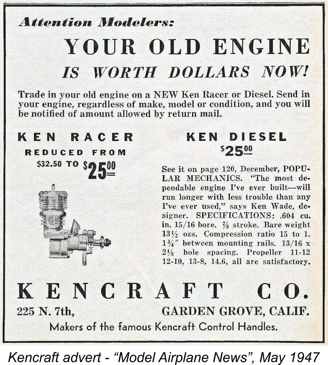
The engine continued in small-scale production through 1946, still being advertised at its original price of $32.50. Marketing efforts continued into 1947. However, it would appear that sales must have been flagging as of early 1947, because by May 1947 the price of the Ken 61 had been reduced from $32.50 to $25.00, thus substantially undercutting the $35.00 price tag of the contemporary McCoy 60. Interestingly, the Ken 61 was referred to in the company’s May 1947 “Model Airplane News” advertisement as the “Ken Racer” to distinguish it from the Ken diesel (see below) which was actually the main focus of the advertisement, being offered at the same $25.00 price. It’s also interesting to note that by May 1947 the Kencraft company was offering a trade-in scheme whereby a prospective customer could receive credit towards the purchase of a new Ken engine by sending in his old motor. To me, this speaks of a certain measure of desperation in trying to sell off accumulated unsold stocks of engines. It actually seems probable that production of the Ken 61 had ended by that time. The Ken 61 was included in a table which formed part of Edward G. Ingram’s article entitled “Model Motors for 1948” which was published in the January 1948 issue of “Model Airplane News”. However, it was not mentioned at all in the main text of the article. Moreover, that is the last media reference to the engine that I can find. Presumably the glow-plug revolution which began in November 1947 was the final straw which killed it off. Other Kencraft Developments
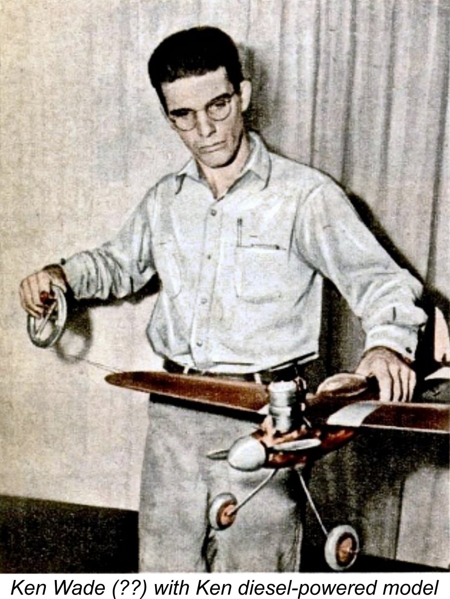
The same December 1946 advertisement is significant in that it includes the first of only two surviving media references of which I’m currently aware to the fact that Kencraft was then experimenting with model diesel technology. Check out the fine print in the bottom left-hand corner ....... At the time there was considerable interest in model diesels among American manufacturers, since the glow-plug had yet to appear in commercial miniature form and the use of compression ignition allowed modellers to dispense with the heavy, bulky and potentially unreliable spark ignition support system. Indeed, the years 1946 and 1947 were to see the introduction of a surprising number of model diesels It appears that by the latter half of 1946 Ken Wade had become aware of the application of compression ignition to model engines and had decided to test the concept for himself. The result was the production of a small handful of compression ignition versions of the basic Ken 61 design. There’s some debate over the precise form(s) that these diesel models may have taken, but the illustrated example represents what Bob Kautzman believed to be the “standard” form of the Ken diesel. The engine uses the standard 61 front housing and induction system apart from the omission of the turbo fan. The standard cast alloy cylinder head is replaced with a finless steel item having no provision for compression adjustment while running. The standard timer is replaced with a nicely machined cover. Finally, the diesel used a stronger con-rod which was machined from solid stock rather than being cast. The December 1946 advertisement which was reproduced earlier mentions the Ken diesel almost in passing in the bottom The May 1947 advertisement is highly significant for other reasons. Firstly, it includes some otherwise unrecorded technical information on the Ken diesel, including the fact that its fixed-compression head was set at a ratio of 15:1 – relatively low for a diesel. The quoted bare weight of the engine was 13½ ounces, a little less than that of the spark ignition version. The absence of the plug, timer and turbo fan doubtless accounted for this. In addition, a number of propeller recommendations were cited. The engine was said to perform equally satisfactorily with 11x12, 12x10, 13x8 or 14x6 airscrews. The advertisement also included the following quote from Ken Wade regarding the Ken diesel: “The most dependable engine I’ve ever built – will run longer with less trouble than any I’ve ever used”.
It’s very likely that the individual holding the model is none other than Ken Wade, although this cannot be stated as a confirmed fact. Regardless, the motor and model must have been in existence as of October 1946 at the latest in order for the photograph to have been taken in time to meet the editorial deadline for the December 1946 issue of “Popular Mechanics”. This confirms that the Ken diesel was developed and initially tested during the latter half of 1946. Despite the cited advertising references to the Ken diesel, it remains an open question whether or not this model really achieved what we might consider to be full production status. There’s no doubt at all that the engine was offered for sale and was promoted quite vigorously. However, the miniscule number of survivors suggests that the Ken diesels which undoubtedly were produced may have constituted a very small experimental prototype batch built purely to test the market rather than representing an actual commercial production.
Persuasive evidence also exists to show that Ken Wade experimented with a variable compression head for this engine. Bob Kautzman had an example of such a head which fitted the basic Ken crankcase perfectly. Interestingly enough, this head follows the pattern established in far later diesel designs by having the contra-piston operate in a subsidiary bore formed in the head itself rather than being fitted into the main bore. Another seemingly experimental project which evidently never reached production status was a .65 cuin. glow-plug model. Given the fact that Ray Arden didn’t launch the commercial miniature glow-plug until November 1947, this must date from some time in 1948, presumably after the demise of the Ken 61 spark ignition and diesel models. Bob Kautzman advised that Graham Podd had located two examples of this model, both utilizing standard .61 crankcases which bore very late serial numbers (2055 and 2086). It seems The glow-plug units were bored out to yield the slightly higher displacement. They also abandoned the turbo induction arrangement, instead using conventional FRV induction through a hollow crankshaft and thus dispensing with the induction bypass bulge in the front housing. In fact, apart from the crankcase, none of the components of this model were interchangeable with those used in the spark ignition Ken 61. Finally, Bob Kautzman also acquired a pair of Kencraft crankcases which are equipped with sideport induction bosses at the rear. It’s hard to understand why Ken Wade would revert to sideport induction after introducing what seems to have been a fairly powerful .61 cuin. rotary valve model, but the fact that one of these cases is vertically shortened as if to accommodate a diesel cylinder suggests that it post-dates the “standard” spark ignition model. The other case has an unfinished intake stub and is equipped instead with an FRV front bearing housing which has no provision for a timer. This actually suggests that it may have been envisioned from the outset as a glow-plug model. We’ll almost certainly never know what prompted Wade to produce these cases, and when he did so. Conclusion
However, that’s only one way to look at it. In terms of its technical attributes, the engine was truly unique – there’s nothing else quite like it! Viewed strictly as a technical achievement, it’s impossible not to see the Ken 61 as a brave and in many ways successful attempt to combine not one but two very unique design concepts – crankcase supercharging and the reverse location of the usual disc valve induction system. The fact that the combination may have been in essence a sales gimmick which didn’t result in any performance break-through in no way detracts from the creativity and ingenuity of its designer, Ken Wade. Regardless of its failure to set the world on fire performance-wise, I remain firmly of the opinion that the Ken 61 is one of the most interesting and creative racing engine designs of them all when viewed from a purely technical perspective. I hope that I’ve convinced at least some of you of the merits of my take on this fascinating design! ________________________________ Article © Adrian C. Duncan, Coquitlam, BC, Canada First published December 2017
|
 In this article, I’ll summarize what is known about one of the often overlooked and (in my personal view) somewhat under-appreciated pioneering model racing engines from America. This is the Ken 61 from sunny California. As you’ll soon learn, although it was no world-beater in performance terms, this was one of the most technically interesting and unusual model engines ever to put in a market appearance!
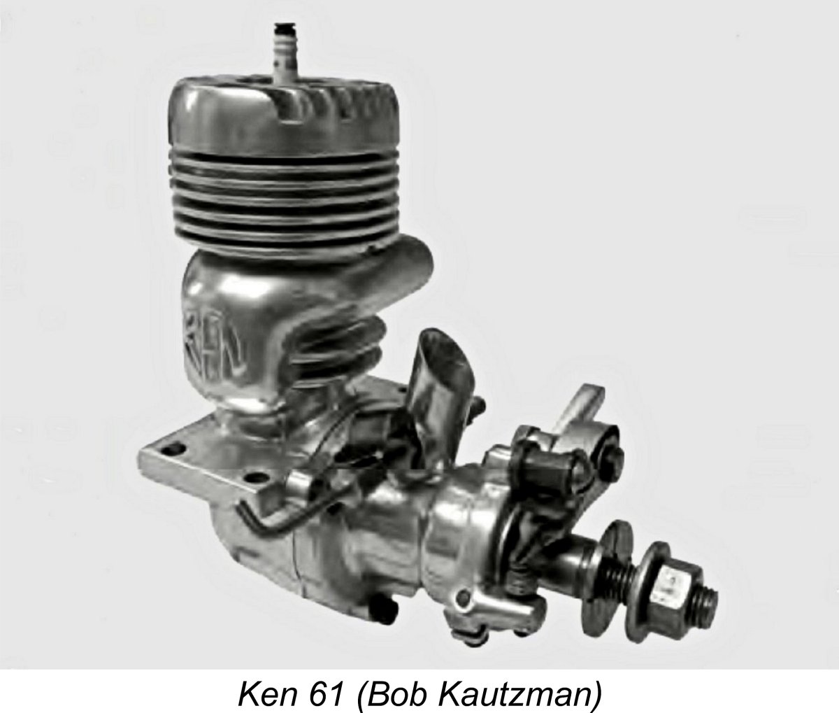
 The Ken engines were manufactured by the Kencraft Company of 225 North 7th Street, Garden Grove, California. Garden Grove is a city in northern Orange County lying some 34 miles south-east of central Los Angeles. At the time of which we are speaking it was a community of relatively modest size, but the post-WW2 boom led to its rapid expansion. It was eventually incorporated as a city in 1956, having a population at that time of around 44,000 people. It has since grown to a population of over 175,000.
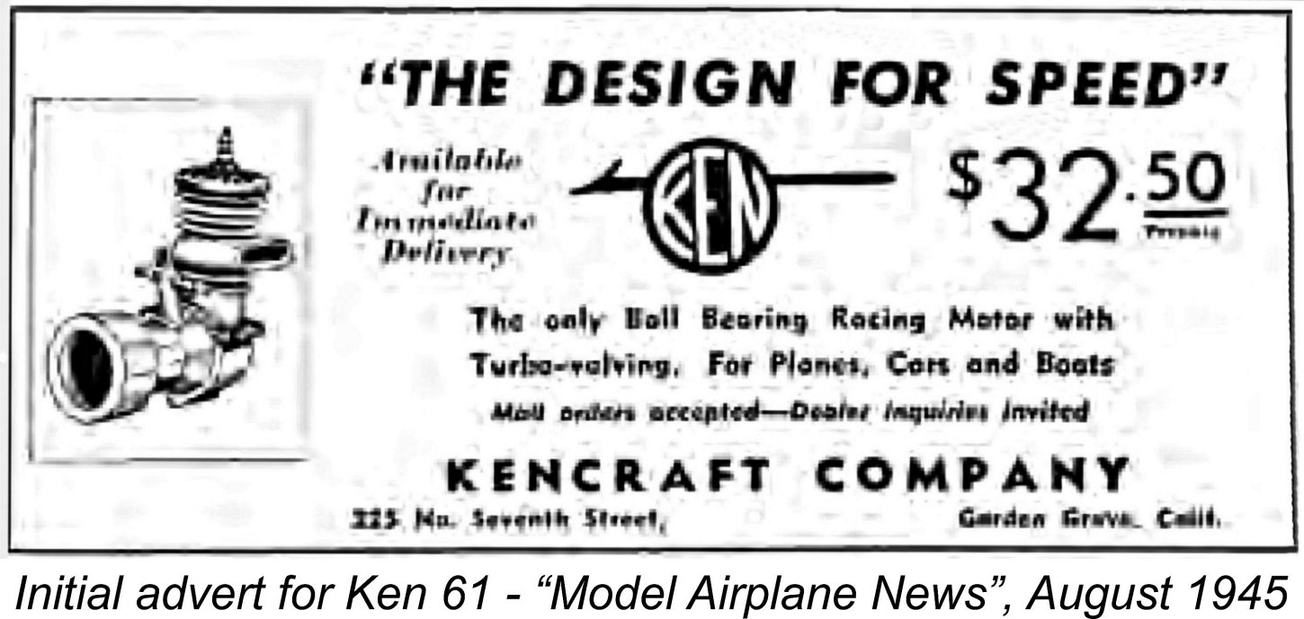 What is known is that at some point immediately before or perhaps during WW2 Wade became interested in the then-developing sport of model car racing. One of his engines was tried out in a
 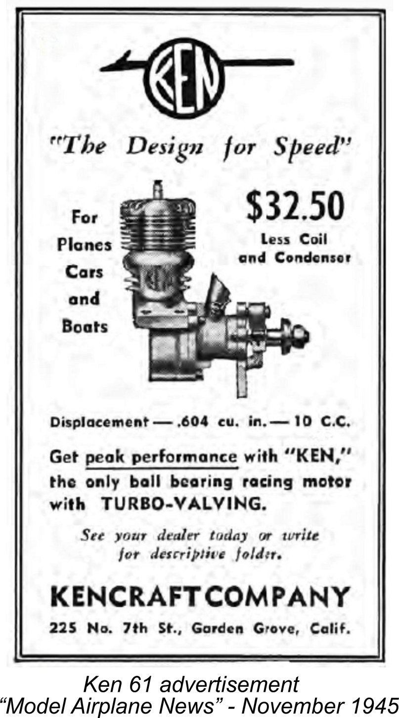 The initial advertisement for the engine which is reproduced above appeared in the August 1945 issue of “Model Airplane News”, actually several weeks prior to the Japanese surrender on August 14
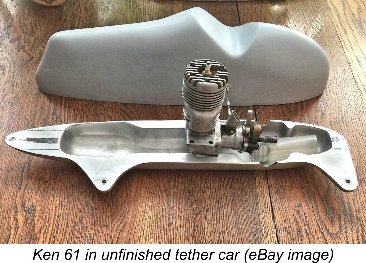 At the outset, the primary intended application of this engine appears to have been tether car racing, which was then the largest market sector for big-bore model racing engines. The artist’s impression which was featured in the initial advertisement showed the engine equipped with a flywheel for just such a service. Even today the odd example still turns up now and then in a tether car context, as illustrated here.
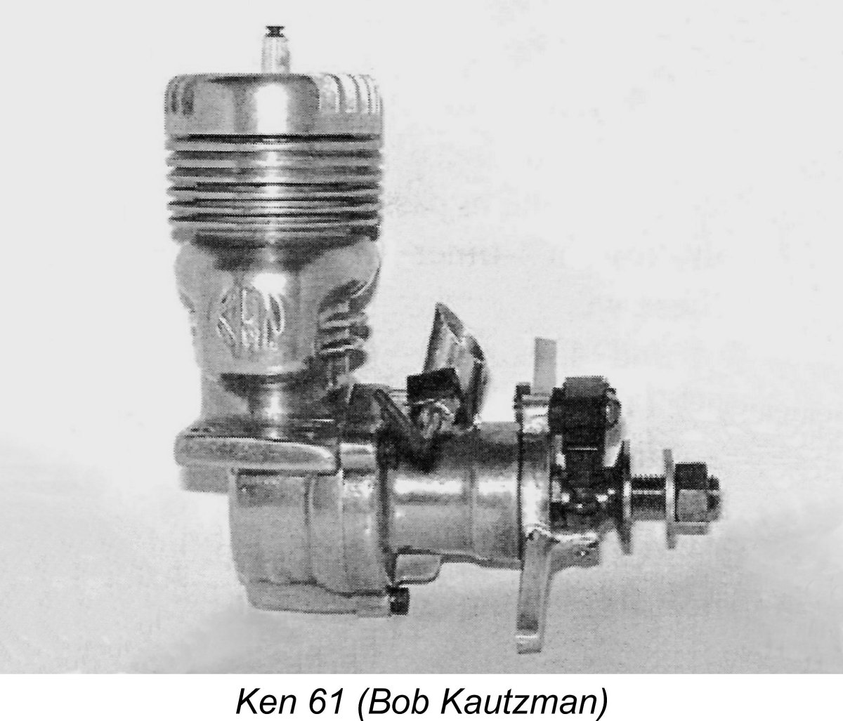 As usual, we’ll begin with a few statistics. Bore and stroke of the Ken 61 were 0.937 in. (23.80 mm) and 0.875 in. (22.25 mm) respectively for a calculated displacement of 0.604 cuin. (9.89 cc). Naturally, the engine used spark ignition – the appearance of the commercial miniature glow-plug was still well over two years away. Bare weight with plug and timer but minus the ignition support system was a not unreasonable 15.5 ounces.
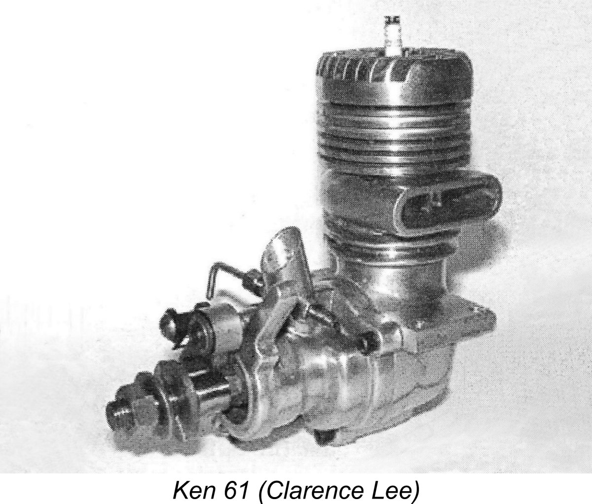
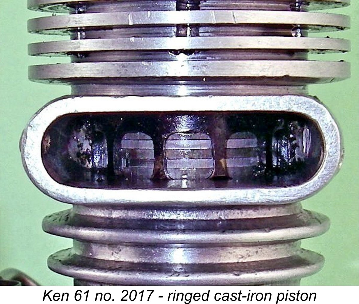 The third configuration which is occasionally encountered is a conventional set-up involving the use of a cast aluminium alloy piston with two rings. These latter pistons have high McCoy-style crowns. One might think that this would be the "ultimate" development configuration, but in fact my ringed cast iron piston example number 2017 is one of the last examples made. Even one of my two lapped piston "bones" motor is a late example bearing the serial number 1977 - the other bears the number 1406.
 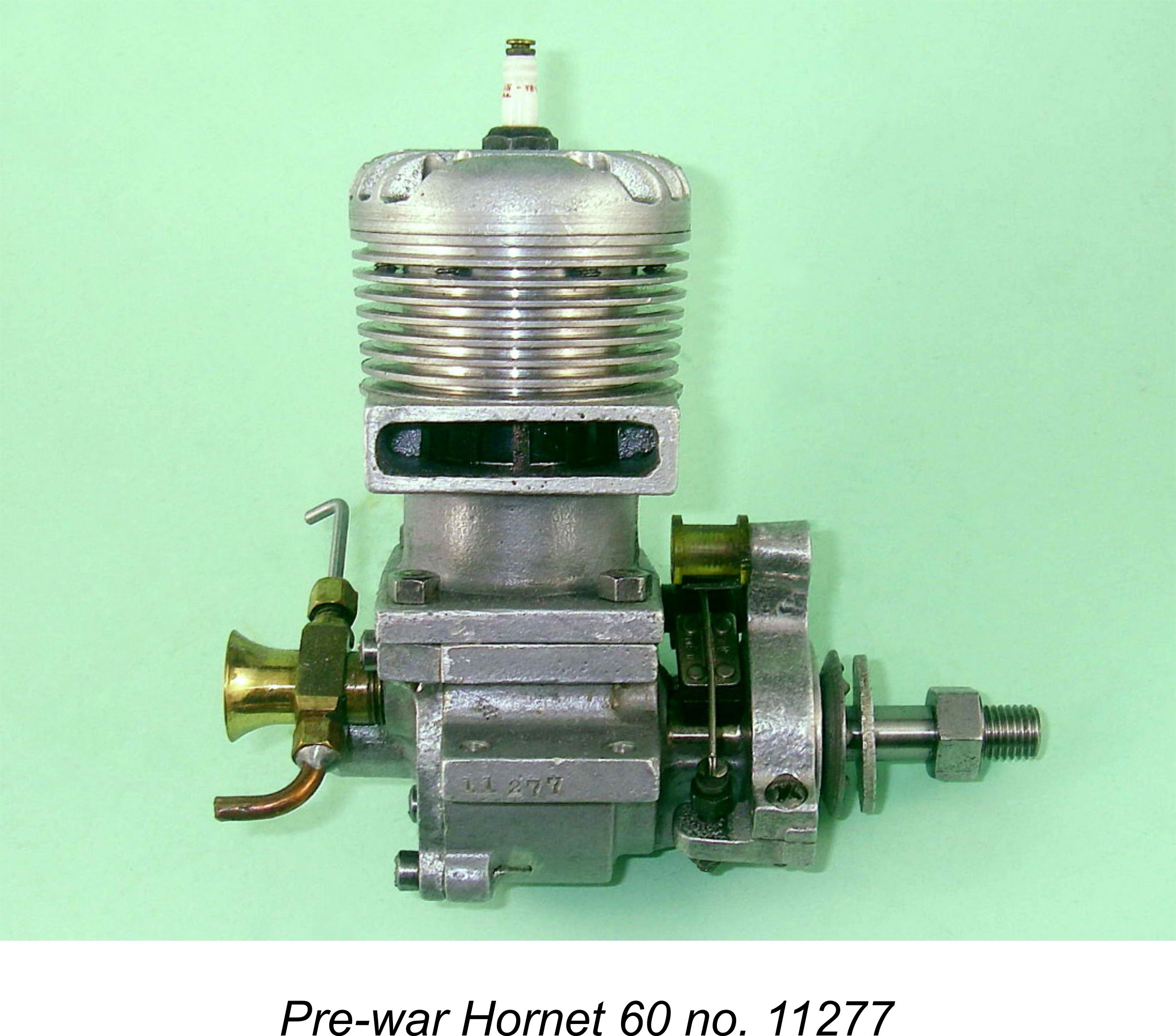 Ken Wade had doubtless noted the efforts made by his fellow Californian tether car racer
 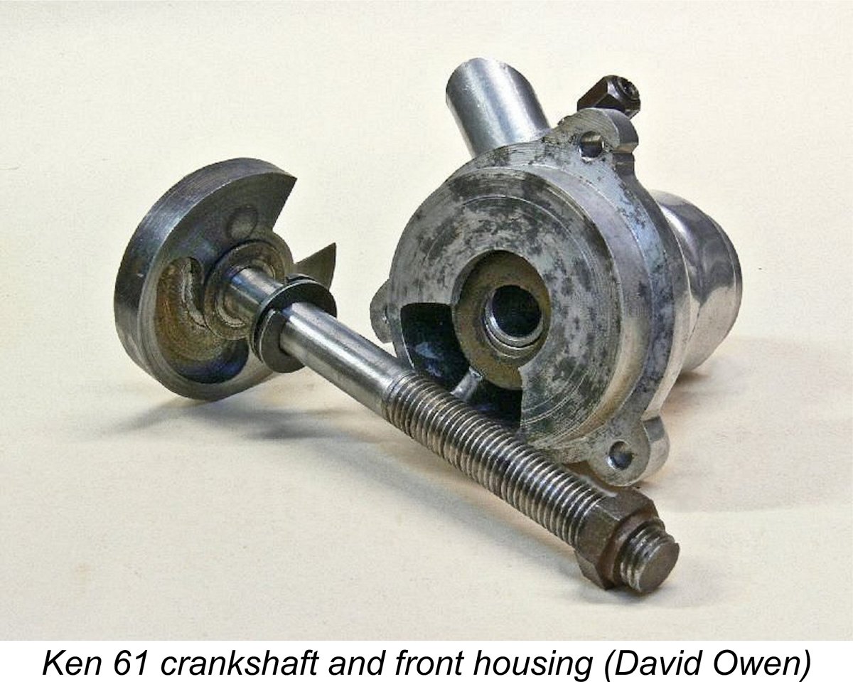 To begin with, the engine’s crankshaft was a composite affair which was brazed together from three separate components – the crankpin, crank disc and nominally
 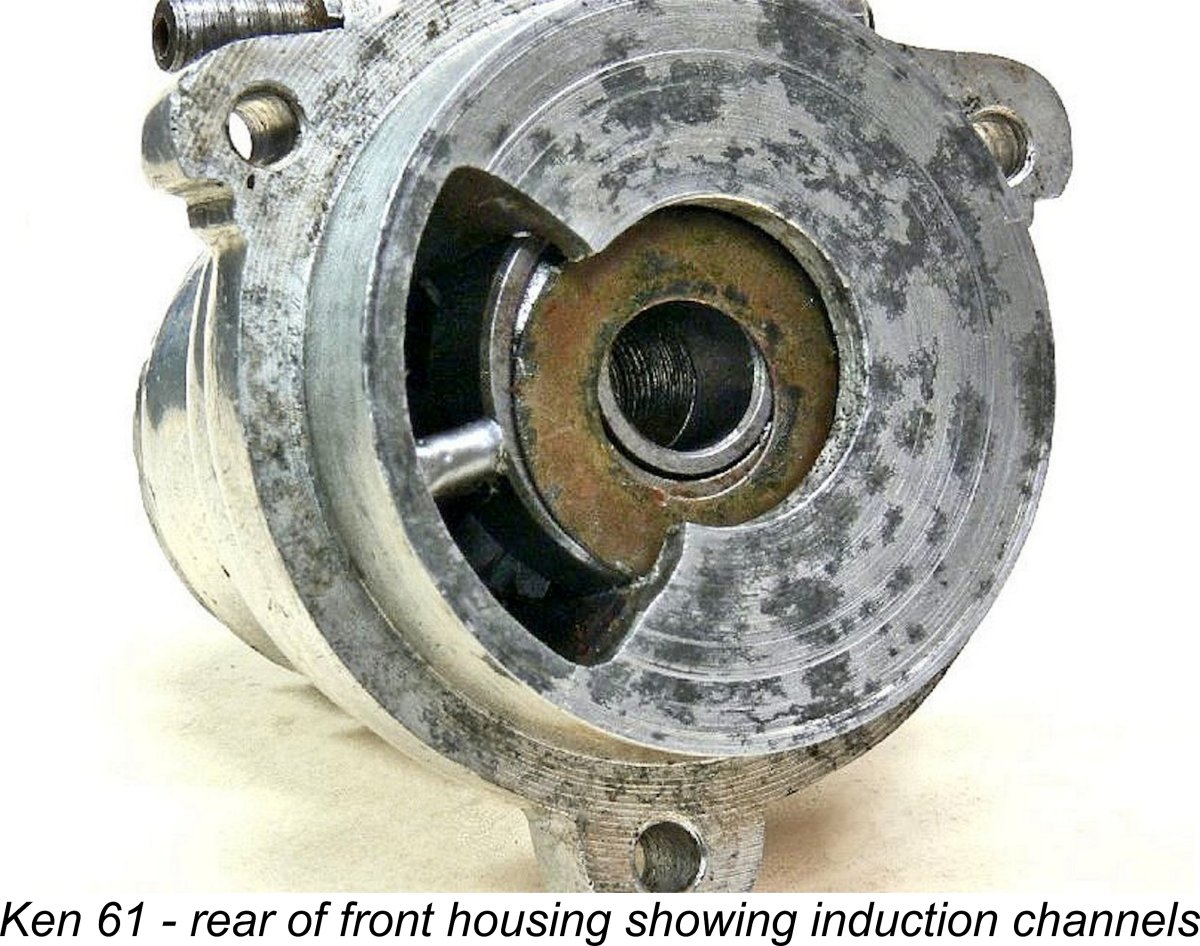 Since the crankshaft main journal was solid throughout, an alternative pathway had to be created for vaporized fuel mixture to reach the crankcase. To this end, a pair of axially-oriented channels of quite generous cross-sectional area were provided in the rear inside wall of the ball race installation bore to allow vaporised fuel mixture to flow around the outer circumference of the rear ball race and into the crankcase. These two channels were accommodated by a hollow “induction bypass bulge” cast into the rear left-hand side of the front housing.
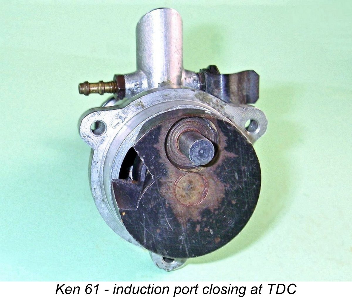 If mine may be taken as a representative example, the induction system opened at 45 degrees after bottom dead centre (BDC) and closed at 30 degrees ATDC for a total induction period of 165 degrees.
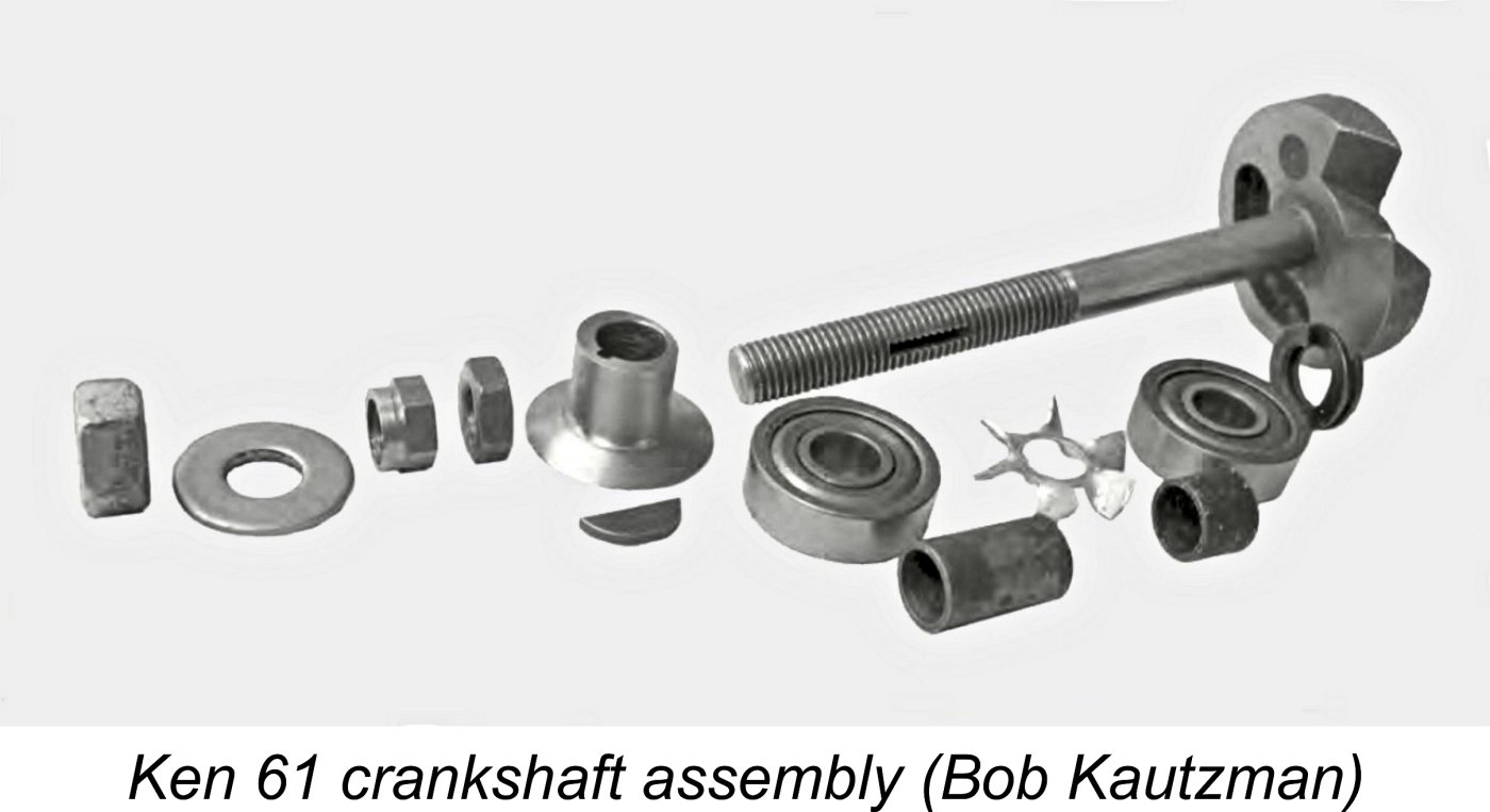
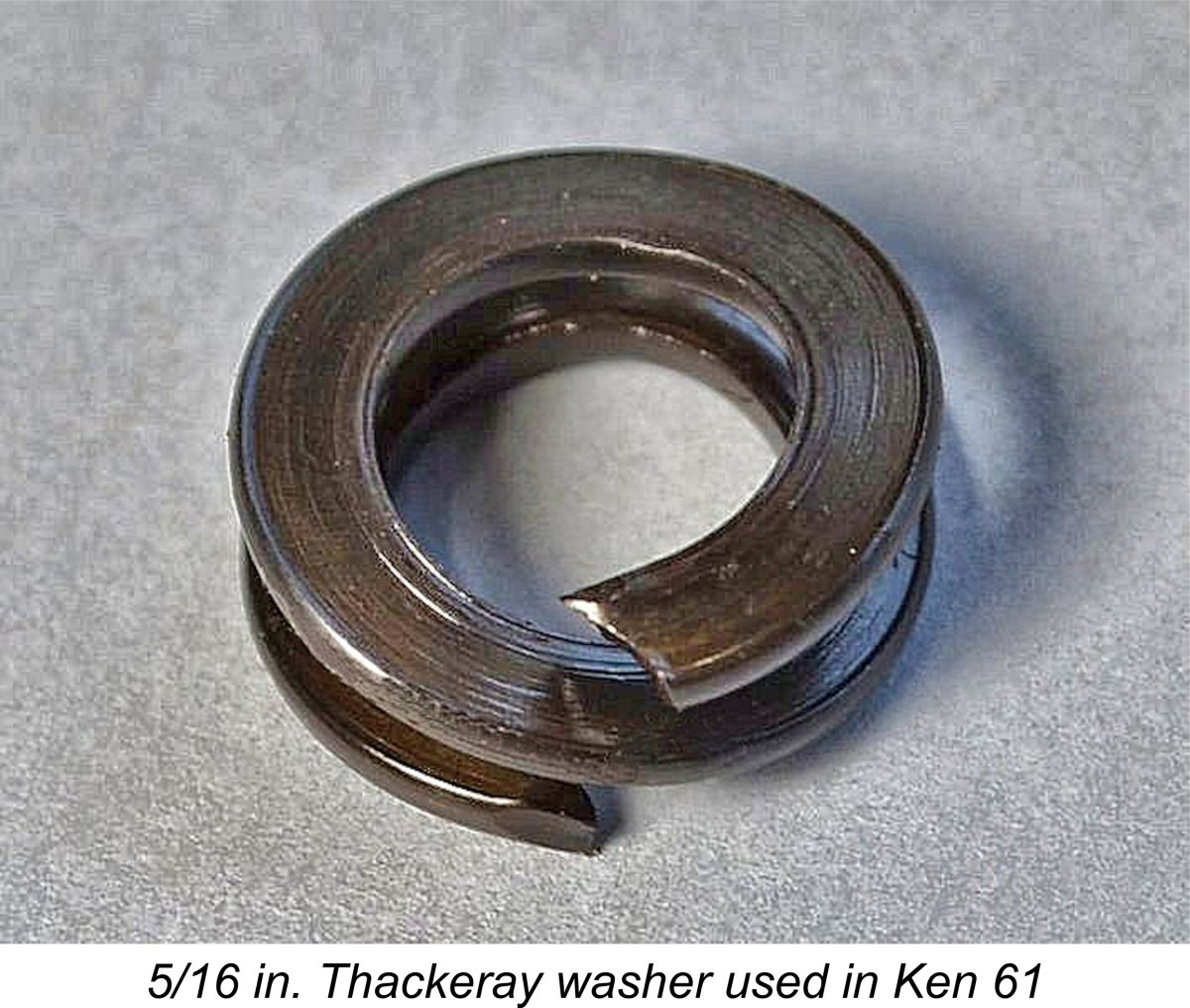 To meet both of these requirements, a flat-section high tension
 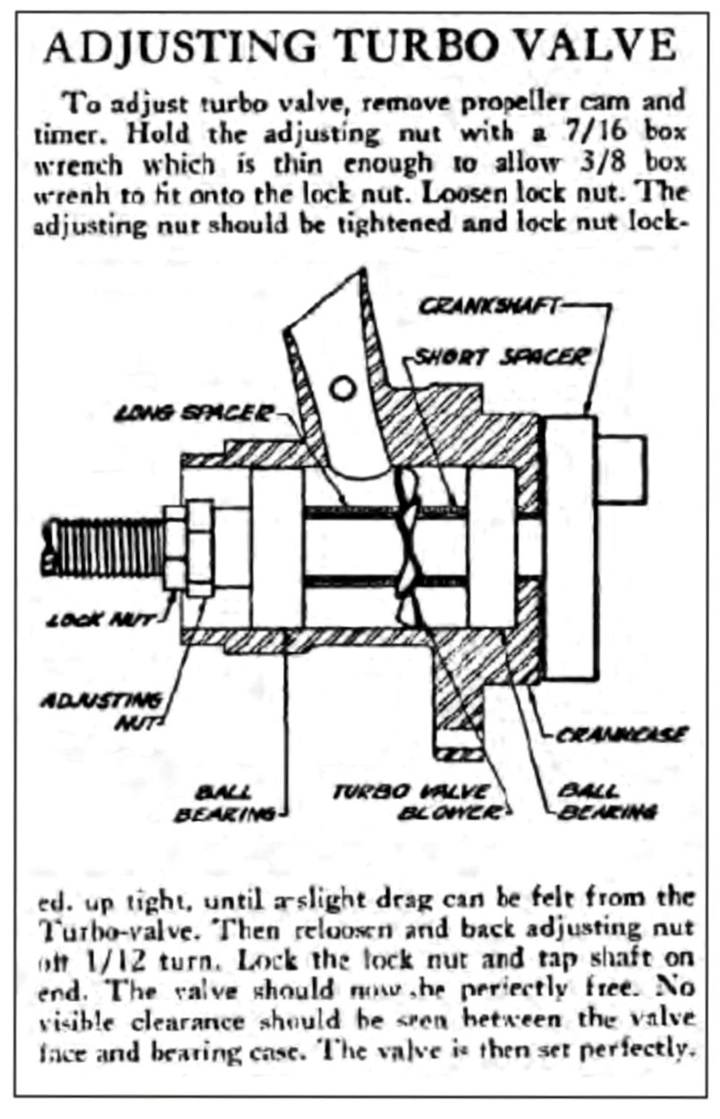 rearward thrust acting upon the crank disc would naturally tend to push it away from the rear face of the front housing to the extent permitted by the sleeve nut at the front of the shaft. Clearly, any significant separation would terminate the intimate proximity of the two surfaces upon which the engine’s base compression would depend.
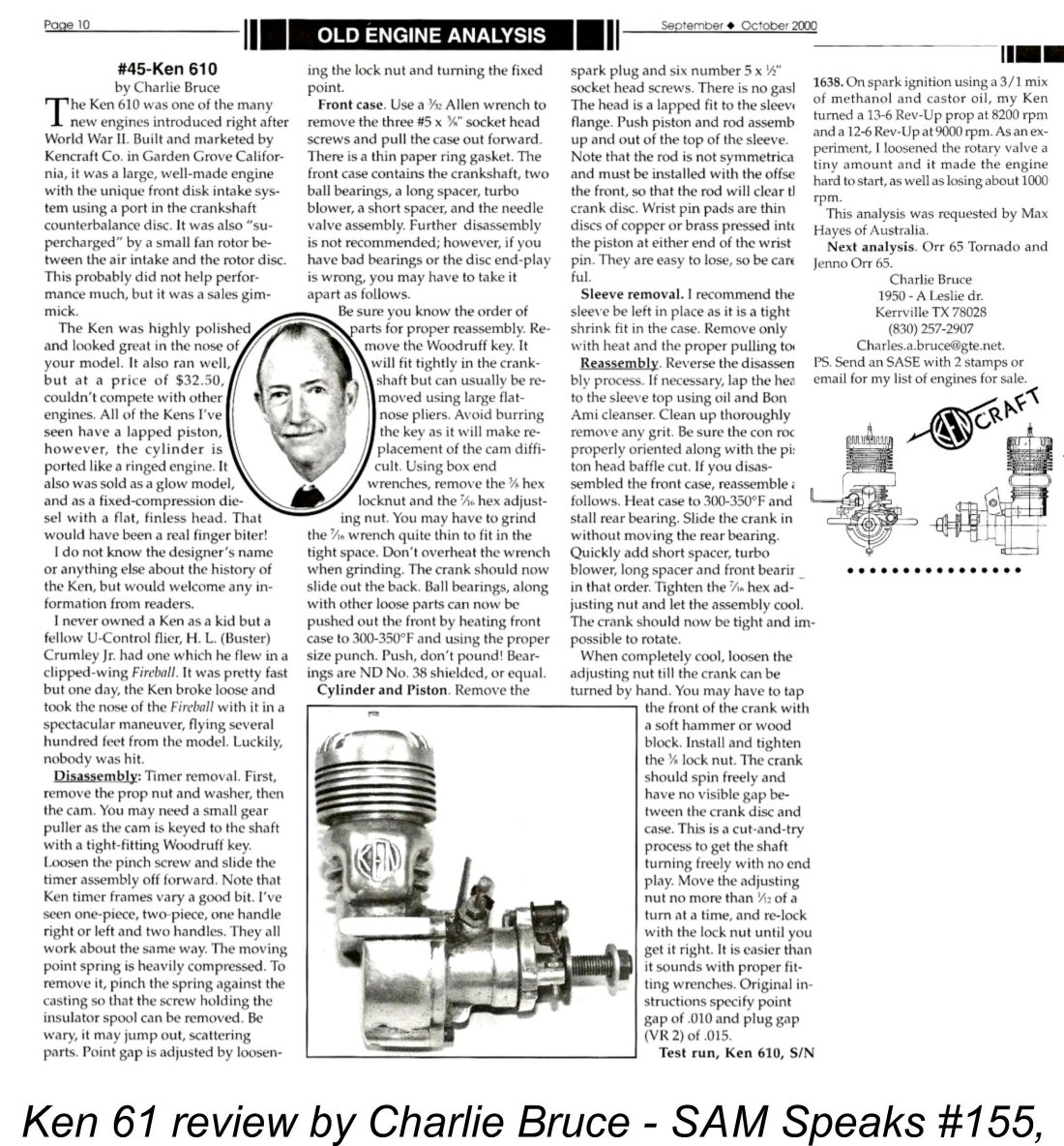 The previously-mentioned review of the Ken 61 by Charlie Bruce included very detailed instructions for adjusting the system, even going so far as to describe the procedures necessary for complete dismantling and re-assembly of the front end. I must once again add my own voice to Charlie's strong recommendation that complete dismantling be avoided unless absolutely necessary. That said, Charlie's article is well worth reading in order to gain a full understanding of the intricacies of this very unusual assembly.
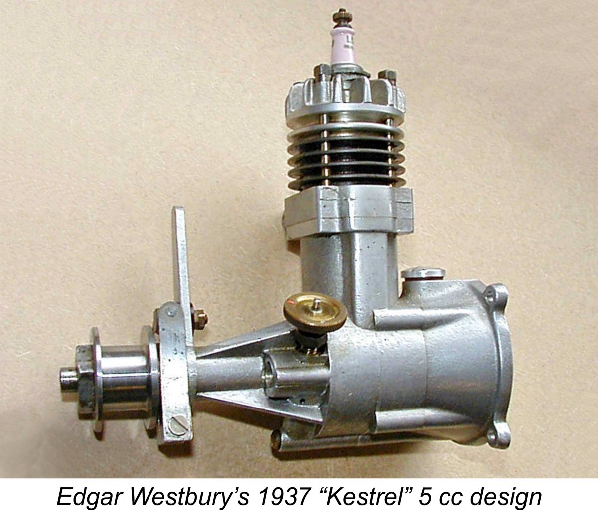
 All of the Ken engines bore serial numbers, generally stamped on the underside of the stiffening web which traversed the integral backplate at the rear. The serial number sequence for the standard Ken 61 started at engine number 1000 – a very common practise at the time since it gave an inflated impression of an engine’s sales success. Charlie Bruce’s test example bore the serial number 1638, while examples bearing the serial numbers 1099 and 1819 have recently appeared on eBay. My incomplete "bones" examples bear the numbers 1406 and 1977, while I have since acquired another near-mint lapped piston example bearing the number 1989. My friend Alistair Bostrom owns engine number 2000.
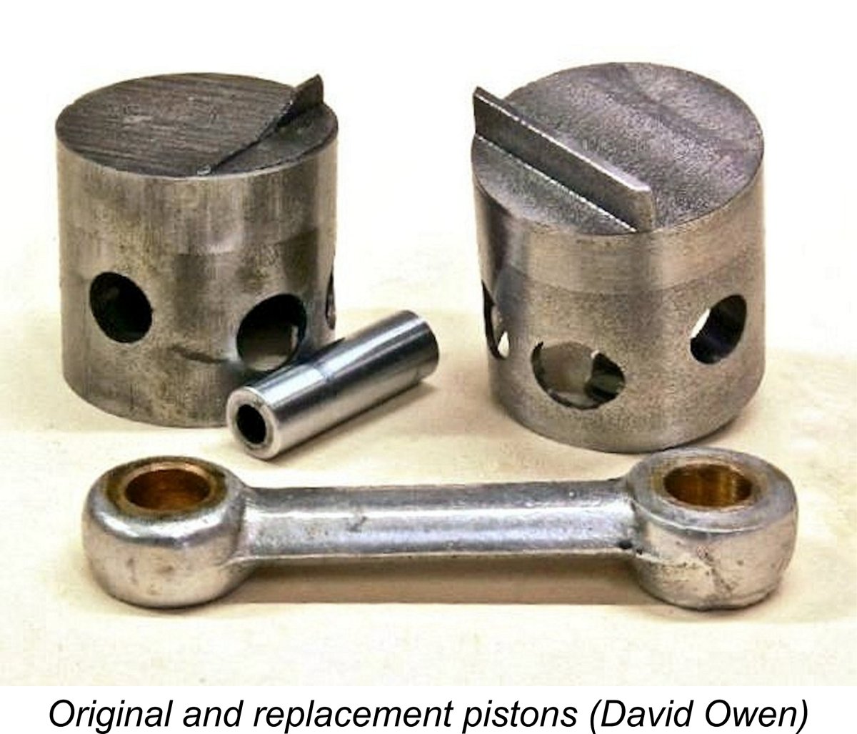 If we were to accept the engine’s claimed output of 0.6 BHP @ 14,000 RPM (“Model Airplane News”, December 1946), we’d have to rate the Ken 61 as a very competitive powerplant by mid 1945 standards. However, there appear to be good reasons to doubt this claim. The previously-mentioned 2015 thread on R/C Groups included some comments and images posted by my late and greatly-missed friend David Owen, formerly of Woolongong, Australia, who reported that back in 2012 he had rebuilt a Ken 61 which had a piston with a broken baffle.
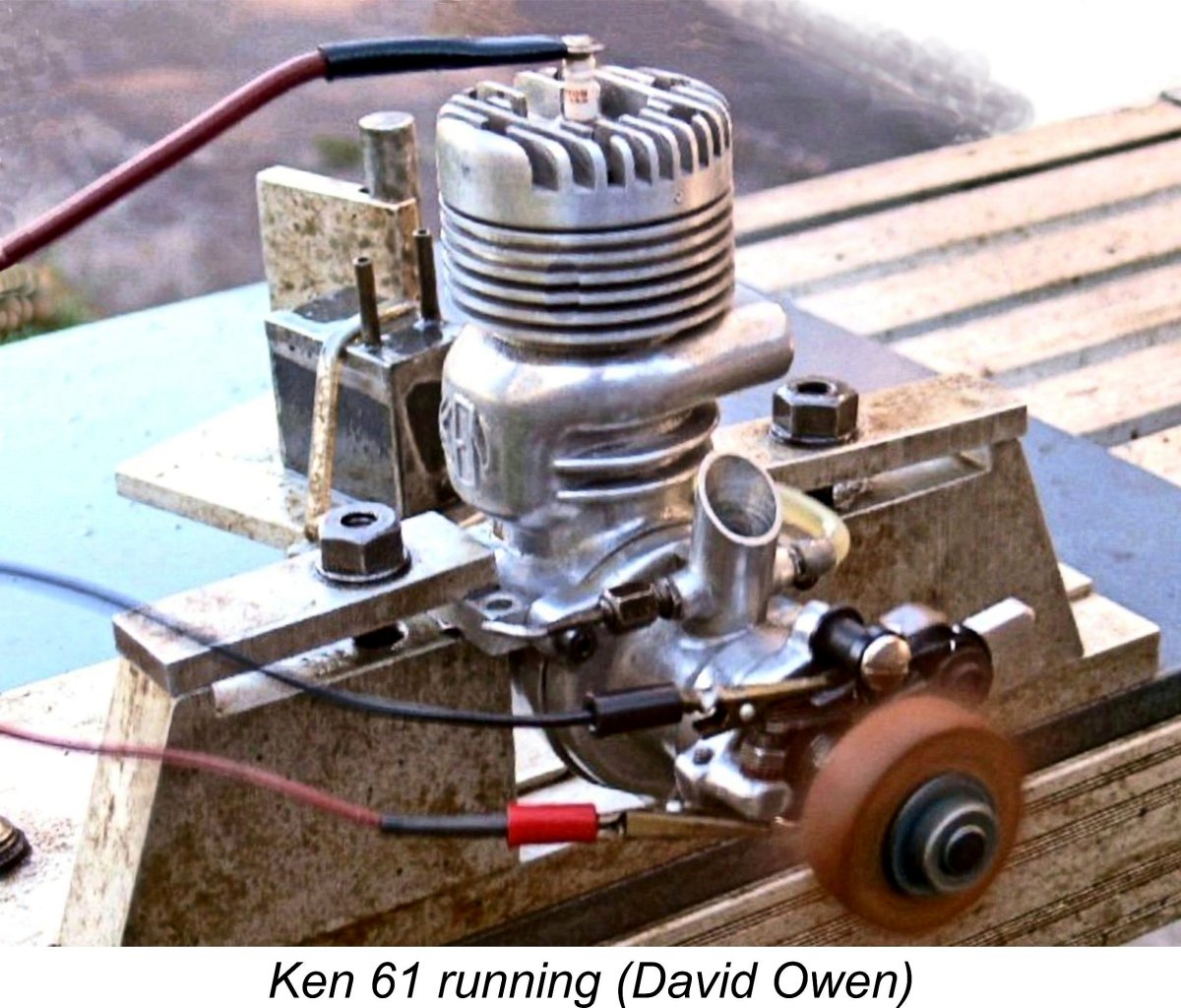 Further confirmation that the Ken 61 was a less than stellar performer came from the previously-noted SAM Speaks article by Charlie Bruce, who reported having test-run his example on a few props. Running on spark ignition using a straight methanol/castor mix, the test engine turned a 13x6 Rev-Up airscrew at 8,200 RPM and a 12x6 Rev-Up at 9,000 RPM. The relatively small increase in speed between the two props clearly implies that the engine was running at or near its peak on the faster prop.
 manufacturer’s claim to the engine’s technical innovation in order to enhance its sales appeal. That of course takes absolutely nothing away from the creativity which went into its design. It’s just that said creativity does not appear to have resulted in anything approaching a performance break-through.
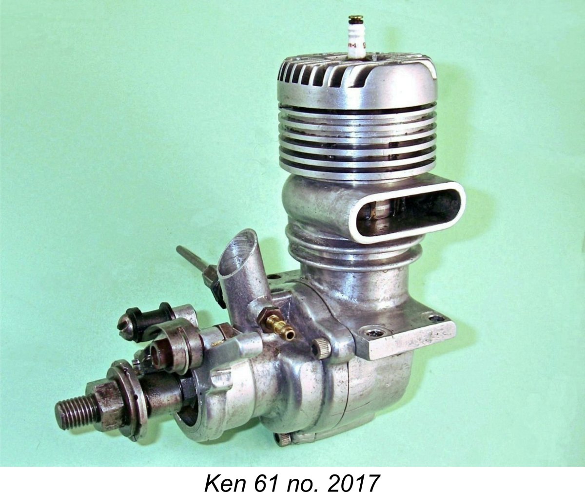 Another potentially problematic consequence of the design is the previously-noted fact that the somewhat skinny crankshaft journal is entirely unsupported between the two ball races. While the close-fitting sleeves which locate and drive the turbo fan do offer some stiffening support, the fact remains that the journal between the races will be subject to substantial cyclic bending stresses during operation in addition to the normal torsional stress reversals. Not a desirable situation from a metal fatigue standpoint……..it would be very important to ensure that any airscrew used was well balanced.
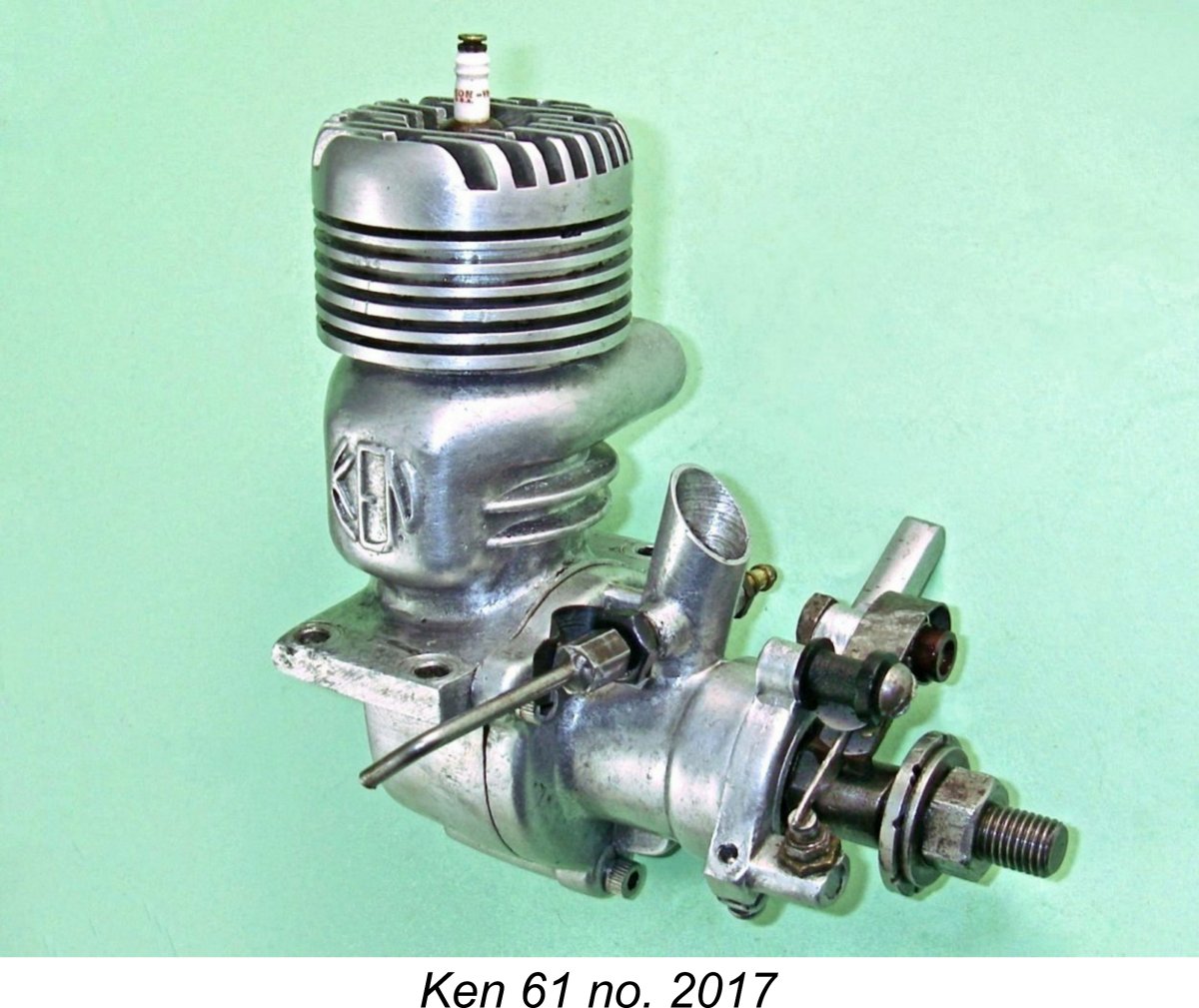 shift of the ball race assembly in the housing (which could potentially occur at higher temperatures under the engine's thrust and vibration) would once again result in part or all of the engine's thrust being transferred to the crank disc/front housing interface. This being the case, it’s a little odd that some means of restricting the potential forward movement of the ball race assembly was not provided, such as a circlip or externally threaded locking ring in front of the forward outer ball race.
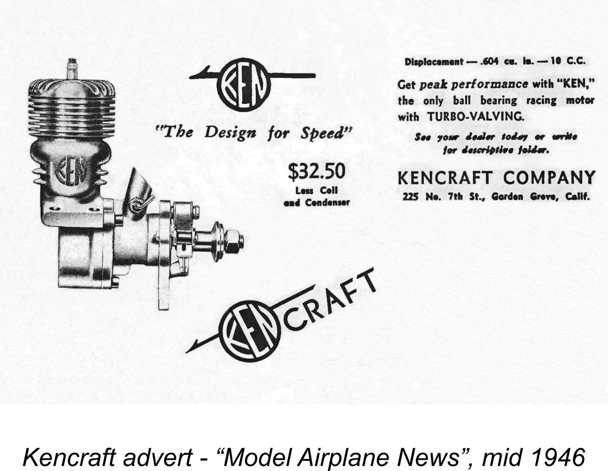 The Ken 61 attracted some early notice from the US modelling media, being mentioned in engine-related articles in both the June 1946 and December 1946 issues of “Model Airplane News”. However, it seems to have increasingly dropped below the radar as 1947 went along, evidently becoming submerged among the increasingly potent alternative offerings then emerging from the likes of
 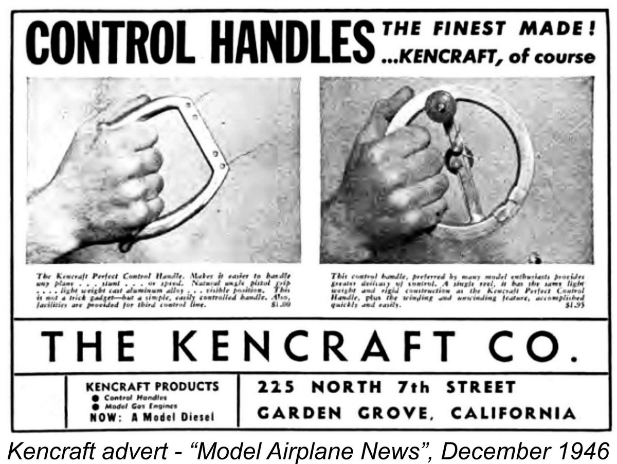 While the Ken 61 was playing out its brief time on the modelling radar, Ken Wade had been applying his creative energies in other directions. As mentioned earlier, Wade developed an early interest in control-line flying. This eventually led to his Kencraft company expanding its product line to include a pair of control-line handles which were first advertised in a half-page placement which appeared in the December 1946 issue of “Model Airplane News”. These handles were cast in light alloy from permanent molds.
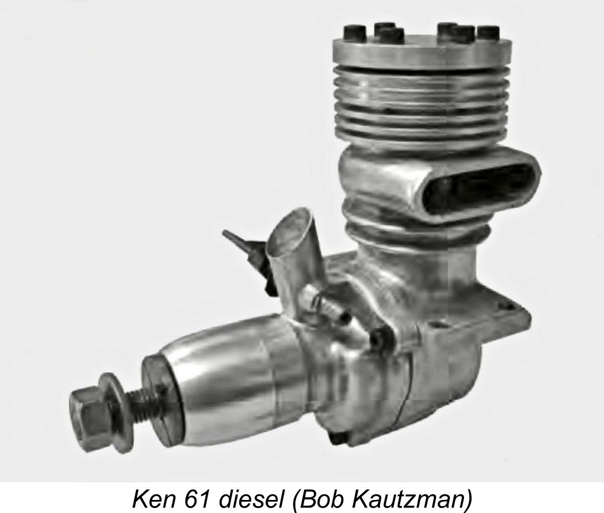
 Clearly, Wade held a high opinion of the running qualities of this engine based upon his own experience. It appears that he had been flight-testing it as of November 1946 at the latest, since the advertisement also makes reference to the engine’s appearance in the
 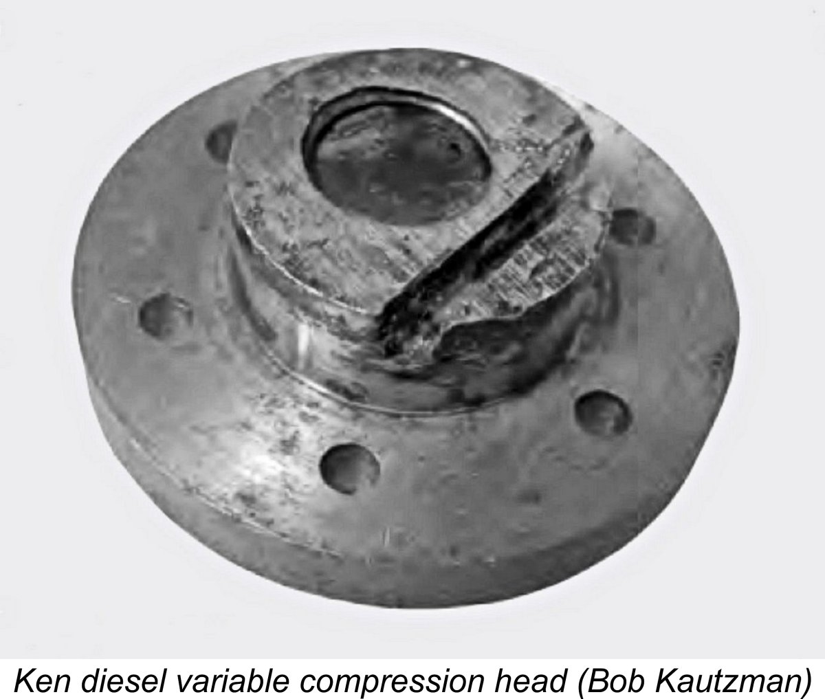 There is evidence to suggest that the Ken diesel was created relatively late in the Ken 61 production cycle. My friend Alistair Bostrom owns Ken diesel no. 2000, while David Garcia reports having similar engines nos. 2012 and 2064. All three diesel model serial numbers of which I'm aware thus lie within the final batch of 100 or so examples. This makes it appear very likely that they were created by fitting a diesel head to a handful of randomly-selected existing spark ignition models within the main serial numbering sequence. They may represent an effort to sell off the remaining stocks by offering a novel technological configuration. My thanks to Alistair for making me aware of this information!
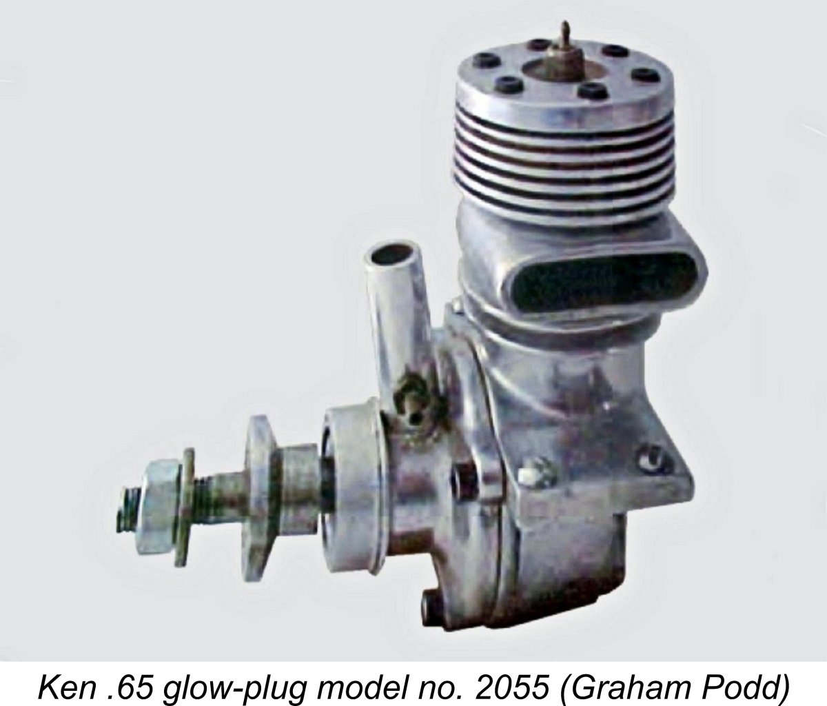
 It’s hard to know where to place the Ken 61 among the racing engines of the early post-war period. I suppose it really depends on how you look at the engine. Viewed strictly as a racing engine, it has to be judged a competitive failure. There’s no evidence that it possessed any real performance advantages even at the time of its mid 1945 introduction. Moreover, any performance merits which it may have possessed at that time were very quickly overwhelmed by the more mainstream designs emerging from other manufacturers.
| |