
|
|
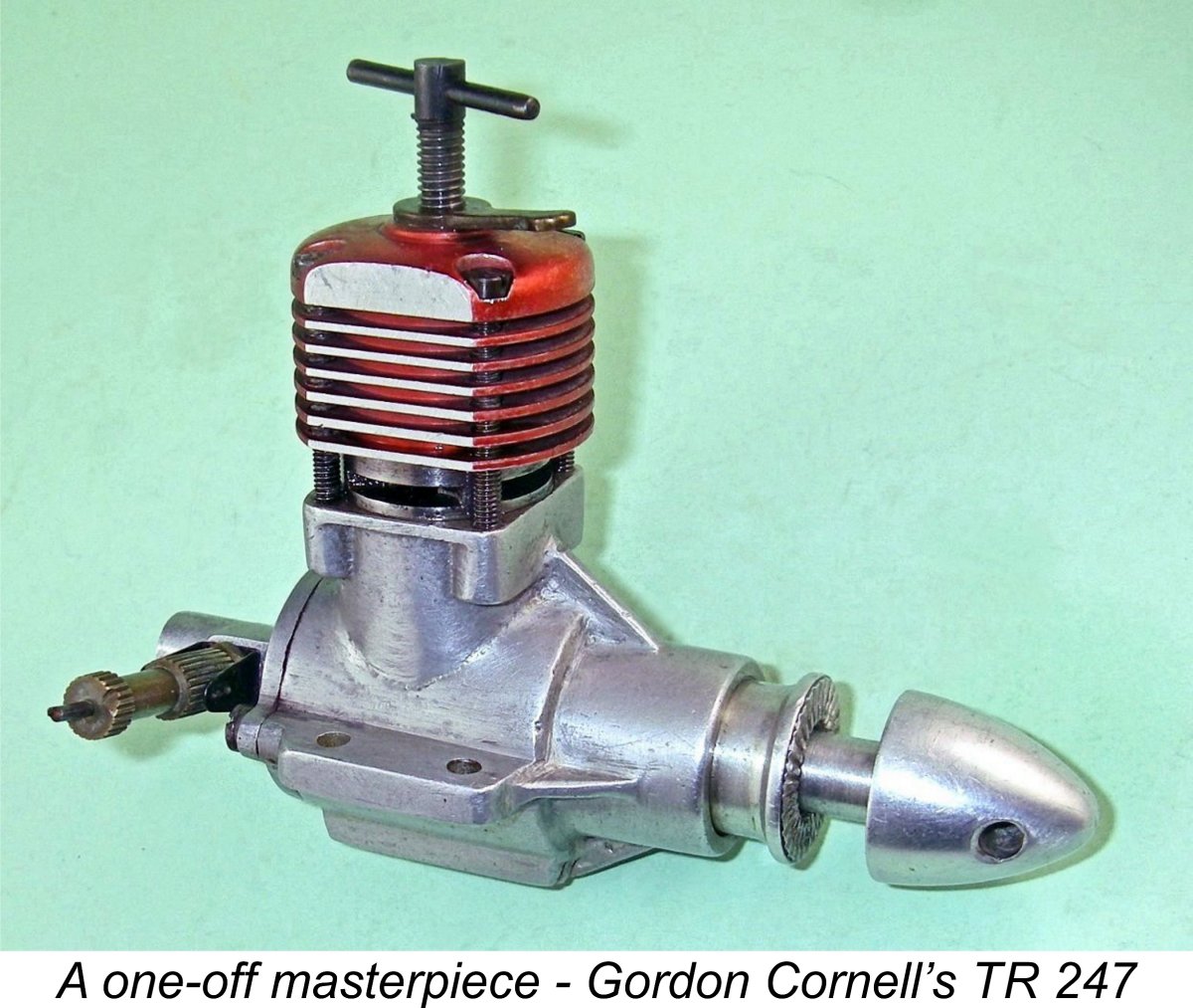
Gordon Cornell’s TR 247 Team Race Special
This is another of my series of articles on model engines from commercial designers and manufacturers which indisputably existed in prototype form but never actually made it into production. Other such reviews have covered the Thermite, AHC and DeLong diesels from America as well as the ETA 15 glow-plug design and the Ten-Sixty-Six 2.75 cc diesel from England. The justification for publishing details of such engines, original examples of which will almost never become available to collectors, is their significance in the historical context of model engine development, very much including the light that they shed upon the careers of their designers and manufacturers. This is another such instance. The writing of this article was made possible solely as a result of Gordon Cornell’s kindness in drawing my attention to the fact that the only example ever made of this particular prototype was on offer on eBay. Happily I was able to win the auction, thus making this historic and unique one-off engine available for inspection, testing and sharing. My very sincere thanks to Gordon! In my earlier article on the TR 148, I covered Gordon’s career up to 1959 in some detail, going through to his time spent helping George Fletcher at International Model Aircraft (IMA). This being the case, I will not repeat that material here - interested readers are referred back to my earlier article. Instead, I’ll pick up the story from the point at which Gordon left IMA to take up the position of chief engineer for E.D. in late 1958. Genesis of the Design As of early 1959 when the then 26 year old Gordon was still settling into his new position, E.D. found themselves in an increasingly shaky financial situation. They had been asked by their bank managers to present a definite plan to reduce the sizeable overdraft which had been created as part of the fall-out from the infamous Purchase Tax case of late 1950, of which much more in other articles on this site. Managing Director Jim Donald passed this responsibility wholesale to Gordon.
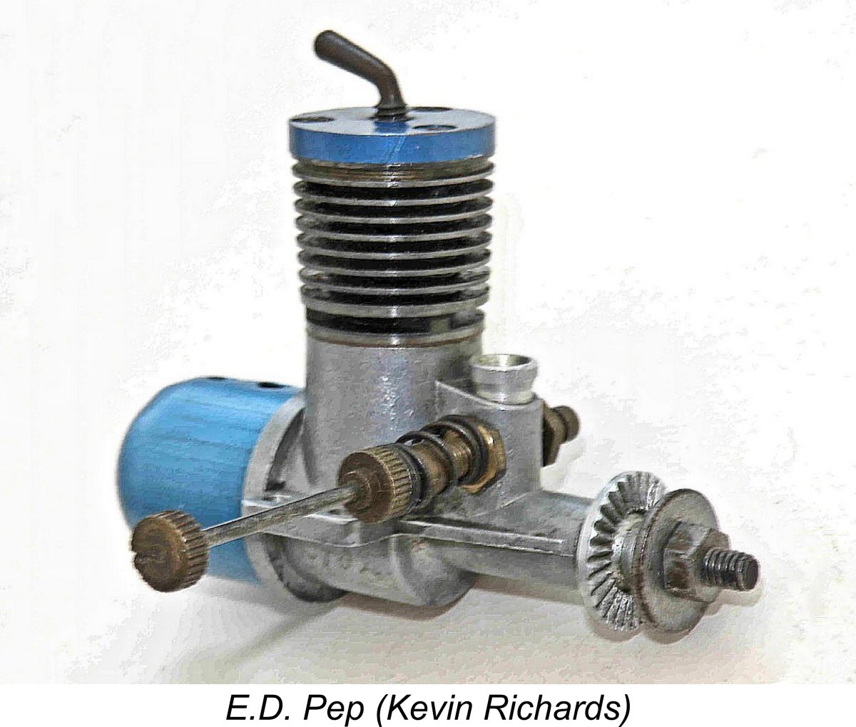
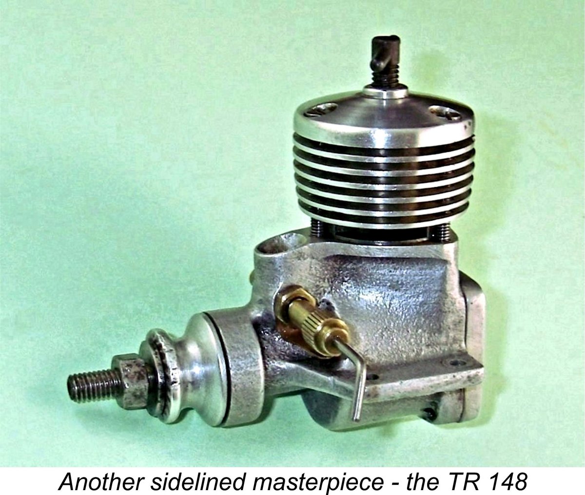
It was thus clear to Gordon that the upgrading of the E.D. range would have to be approached through the incorporation of improvements into the company’s existing designs rather than through the development of all-new models. Sadly, this consigned Gordon’s very promising 1.48 cc TR 148 prototype to the sidelines and thence to model engine history. Initially Gordon focused his attention upon the reconfiguration of the lacklustre 1958 reed valve E.D. 1.46 cc Fury. The existing dies and tooling for that model provided convenient options for the relatively speedy Gordon’s various experimental Fury-based models were flight-tested in a series of his own-design ½A team race models. The result of all this testing and development work was the early 1960 appearance of Gordon's deservedly famous disc rear rotary valve (RRV) Super Fury. This very successful model was aimed primarily at the increasingly popular ½A (1.5 cc) Society of Model Aeronautical Engineers (S.M.A.E.) team race event. Howver, Gordon's work on the Super Fury and the Bee was rudely interrupted later in 1959 by his being called in to salvage E.D.’s 0.81 cc diesel program represented by their proposed E.D. Pep diesel. This project had been initiated in 1959 by E.D. management through an outside contract, amazingly without any consultation with their chief engineer Gordon Cornell. When it became apparent in late 1959 that the design was falling well short of meeting expectations, Gordon was diverted away from the various engine upgrade programs upon which he was then engaged, being tasked Gordon’s hands were tied to a great extent by the fact that many components for the Pep were already in existence. Having paid for those components, E.D. management were unwilling to discard them and start from scratch. The end result was inevitable - the version of the Pep which finally reached the market was a compromise, with a number of design flaws left unresolved. Worse yet, even these compromises did not enable the engine to meet its marketing deadline, since it was not until January 1960 that the Pep was formally announced. It seems possible that a few examples were available in time for Christmas 1959, but in promotional terms E.D. had undoubtedly missed the boat. I’ve recounted the full story of the E.D. Pep elsewhere. It was actually a better engine than its reputation might suggest. Returning from his rather unsatisfactory involvement in the Pep debacle, Gordon got the Super Fury off and running in At the same time, Gordon continued his development work on potential replacements for the larger models in the E.D. range. These included a series of 3.5 cc drum-valve prototype models which might replace the venerable 1949 Mk. IV Hunter. While very powerful, these designs had some limitations as aircraft units due to their weight and other factors. Gordon accordingly re-developed his basic 3.5 cc drum valve design into the very successful Sea Otter 3.5 cc marine diesel. This became a strong seller for E.D. for many years, and deservedly so.
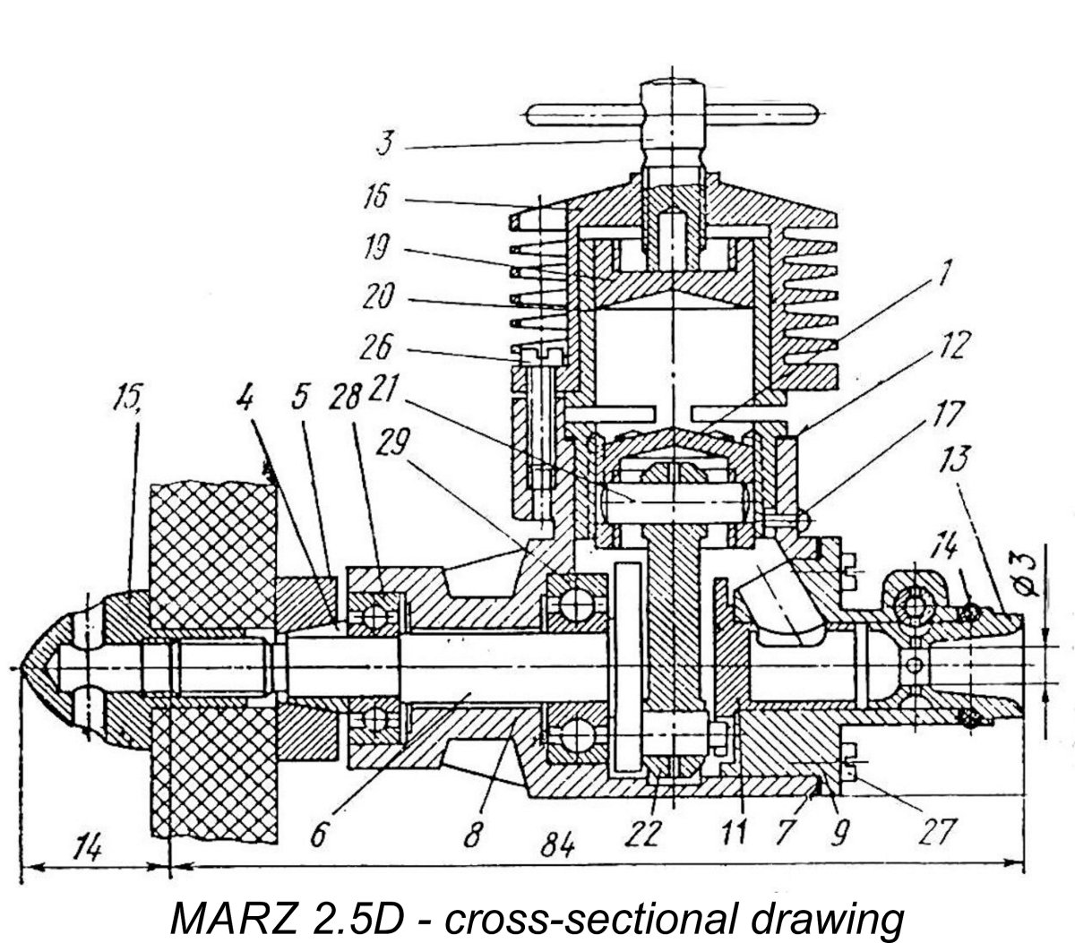
Moving towards this goal, Gordon produced three 2.47 cc designs using rear drum valve (RDV) induction in place of the Oliver’s crankshaft front rotary valve (FRV) system. This design approach was doubtless motivated at least in part by the fact that contemporary high performance FRV diesels (including the Oliver) had begun to experience a problematic incidence of crankshaft failures when pushed to their ever-expanding limits. The drum valve Some ten examples in all of the various 2.5 cc and 3.5 cc prototype units were constructed - my friend Kevin Richrds still owns four of them. Two of Gordon’s 2.5 cc prototype designs used conventional drum valves in which the central gas passage in the drum was open to the crankcase. However, the third and final unit (nearest in the image at the left) employed what Gordon referred to as a "centrifugal" drum valve (perhaps more widely known as a "pipe valve") of the type with which Gordon had previously been associated during his work for IMA with George Fletcher on the FROG 349. Tests showed that this third variant was the most powerful of the three, leading Gordon to use it himself at the 1960 British National Championship meeting. It is this actual engine which is under review here. As stated earlier, I have designated it the TR 247. Having recorded the manner in which this unique powerplant came into being, let’s now have a look at it. We’ll begin with its most interesting feature. The Centrifugal Drum Valve Principle Since it is the most striking feature of the engine which constitutes my main subject here, I think that it’s best to start off with a description of what Gordon Cornell aptly termed the “centrifugal” drum valve induction system. I understand that this type of induction valve is more widely known today as a "pipe valve" based on its use in full-sized engines, but is also referred to sometimes as the "Natalenko valve". In the context of the present discussion I'll stick with the designer's own term. In this arrangement, the “normal” configuration of the drum valve was in effect turned inside out. A “normal” drum valve is more or less a standard FRV induction system applied to a secondary shaft (the drum) located at the rear of the engine and driven by an extension of the crankpin. As with a conventional FRV induction system, the interior of the drum is open to the crankcase at all times, with the induction port The downside of both the conventional drum valve and the FRV arrangement is the fact that the volume of the internal gas passage in the drum or shaft is necessarily added to the overall crankcase volume, potentially limiting the engine's base pumping efficiency upon which its transfer cycle and scavenging depend. The centrifugal drum valve gets around this quite neatly by having the interior of the drum open to the atmosphere rather than to the crankcase – the reverse of the more conventional shaft/drum rotary valve arrangement. The induction port now controls gas access from the interior of the drum directly into the crankcase - the interior of the drum is open to the atmosphere through the centrally-located venturi at all times. The system discharges into the case in a predominantly vertical direction. Hopefully the attached cross-sectional drawing of the Russian MARZ 2.5D will help to clarify a typical arrangement of this kind. The theoretical advantages of this set-up include a shorter and more direct induction gas passage as well as the ability to secure extremely rapid opening and closing of the induction valve. It also promotes a smaller crankcase volume, potentially improving the engine’s pumping efficiency.
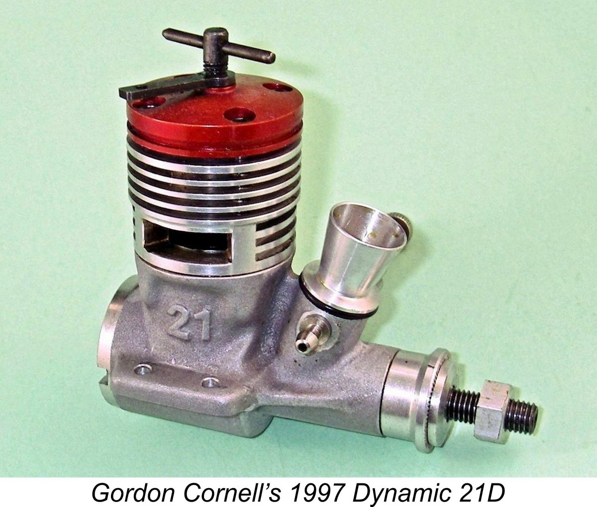
There’s little doubt that Gordon’s use of this arrangement in his TR 247 team race diesel was informed at least to some extent by his earlier experience with the similarly-configured FROG 349 during his time with IMA. He was to use the centrifugal drum valve again a year or two later in his design for the outstanding Dynamic .049 twin ball-race diesel, of which much more elsewhere in due course. Moreover, he was by no means the last team race enthusiast to give it a try - on the contrary, he was the first of many! The centrifugal drum valve arrangement soon gained widespread favour among constructors of leading-edge team race motors, being further developed into what became known as the "bell valve" arrangement which used a far larger drum and a different intake alignment but still followed the same broad principle. The HP company from Austria were early exponents of the bell valve system, the use of which probably peaked in the early to mid However, by the mid 1970’s an Achilles’ Heel had begun to present itself. This was triggered by the realization among top level team race competitors that the oil content in the fuel contributed nothing to range since it did not burn. Accordingly, as of the mid ‘70’s the oil content in team race fuels was steadily decreasing, generally falling below 15% (today, team race oil contents of 5-10% are not unusual). It was soon found by hard experience that the centrifugal drum valve (or bell valve) system had a tendency both to starve the conrod big end bearing of oil and to fall short of providing sufficient cooling for that hard-worked bearing. Engines using the system did not do well on low oil content fuels, causing it to fall out of favour during the late 1970’s and beyond. However, that was over 15 years after Gordon developed his team race special which forms our main subject. The eventual eclipse of the centrifugal drum valve arrangement takes nothing away from the fact that Gordon’s design was at the leading edge of team race diesel development as of 1960. Time to give that very significant motor and its talented designer the credit that they deserve! The Gordon Cornell TR 247 cc Described
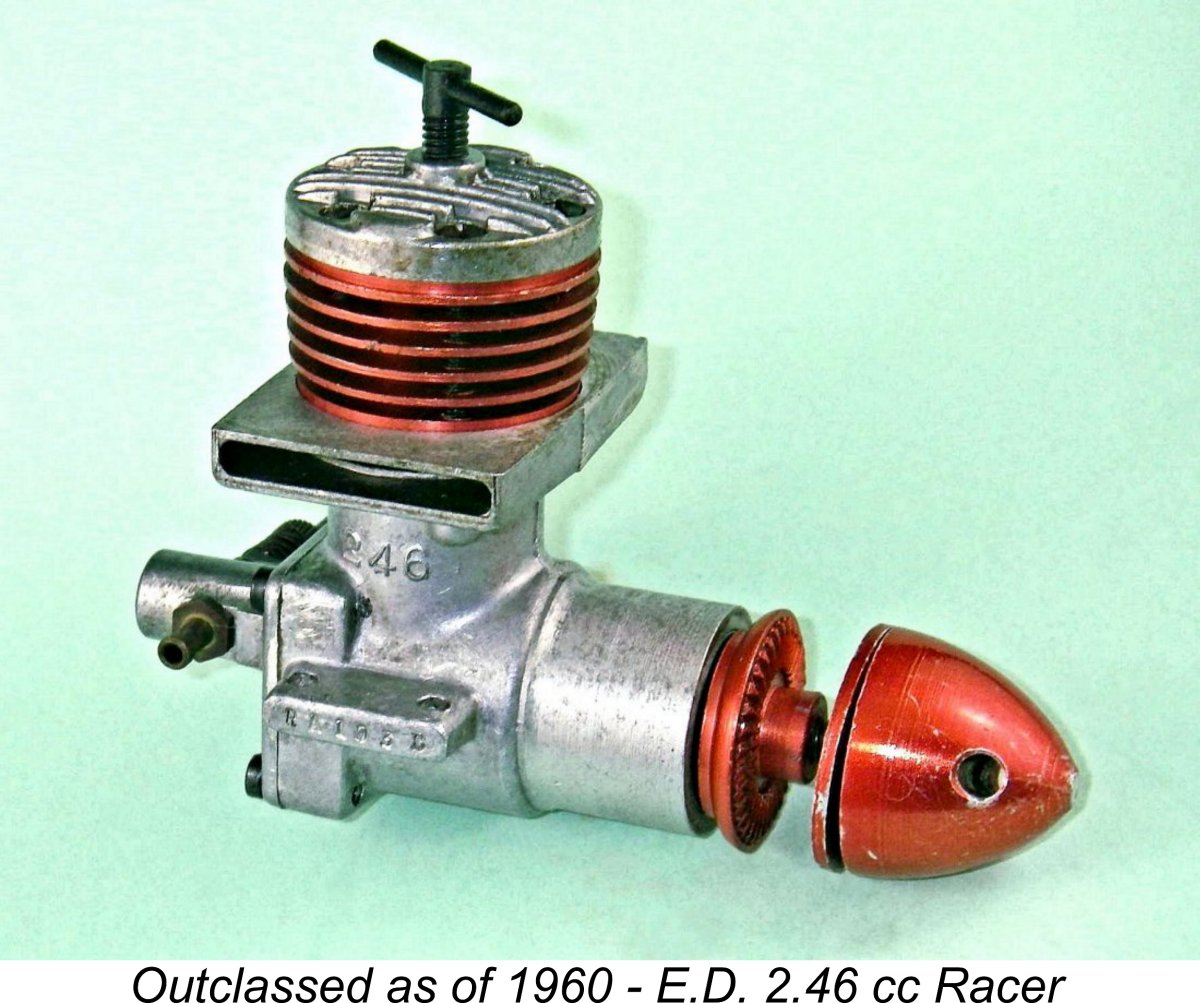
Beginning with the basics, nominal bore and stroke of the TR 247 are identical to those of the E.D. Racer at 0.590 in. (15 mm) and 0.551 in. (14 mm) respectively for a displacement of 0.1509 cuin. (2.474 cc). The TR 247 weighs in at 170 gm (6.00 ounces). All three of Gordon’s 2.47 cc prototypes were constructed around a high-quality sandcast crankcase casting, the second and third of which lacked the exhaust stacks of the Racer. Despite this omission, these were more massive components than that used on the Racer. The main bearing housing with its two ball races was cast in unit with the crankcase on all three prototypes.
The TR 247 uses very few components from the Racer. The crankshaft may be a modified Racer component - I haven’t disturbed the shaft to check. The comp screw, piston, gudgeon pin, rod and needle valve assembly appear to be E.D. Racer components, but everything else is different. Hopefully the attached image of the dismantled engine will help to clarify many of its features. For starters, the cylinder is of quite different design, utilizing a very well-developed expression of the Oliver porting system rather than the sawn slot transfers utilized in the Racer. The porting arrangement follows that used previously in Gordon’s TR 148 model apart from the number of ports. The upper crankcase has four bypass passages of generous dimensions cast into it internally. These register with four upwardly-angled transfer ports formed in the drop-in steel cylinder in the areas between the four sawn exhaust apertures. The transfer ports are of rectangular section, implying that they were first drilled and then squared off by hand-filing. This very exacting work has been carried out extremely neatly and precisely.
And that's exactly what we get! The exhaust ports open quite late at 115 degrees after top dead centre (ATDC) for an unusually short exhaust period of 130 degrees of crank angle and a longer-than-average effective power stroke. The transfers overlap the exhaust almost completely, opening only 5 degrees later at 120 degrees ATDC for a total transfer period of 120 degrees. With the extremely open porting employed, this should be more than adequate at contemporary team race engine speeds. Unlike the earlier TR 148, there is no supplementary sub-piston induction. The cooling jacket is also an all-new component, combining the head and cooling fins into a single slip-on component. Gordon went to the trouble of color-anodizing all three jackets (one black, two red). The jacket and cylinder are conventionally secured using four long screws. The fins on the TR 247 have had milled flats added on each side to reduce the engine’s Gordon confirmed that he used this actual engine at the 1960 British National Championship meeting, unfortunately without making it into the final. The attached image appeared in the contest report in "Aeromodeller" magazine. The TR 247's piston has a conical crown, reflecting its E.D. Racer origin. It is internally milled for lightness, as were the pistons in the later E.D. Racers. The conrod is a light alloy forging - probably the same component used in the Racer. The crankpin has a rearward extension of reduced diameter to drive the drum valve. The drum valve itself is a very substantial piece of work indeed. The backplate has a deep installation spigot at full crankcase internal diameter. The top of this spigot incorporates a very large window, the base of which serves as the register for the drum valve’s rectangular induction port. Incoming mixture from the interior passage of the drum valve is discharged directly into the crankcase in a predominantly vertical direction.
Finally, the needle valve assembly appears to be a standard E.D. Racer combination. It is aligned at a slight upward angle to the right (looking from the rear of the engine), presumably to place it conveniently in Gordon’s model with the engine inverted. As received, the engine was fitted with a spraybar having an external diameter along its working length across the venturi of 0.135 in. (3.43 mm). Reference to Maris Dislers' invaluable choke area calculator tells us that in combination with the 6.35 mm diameter venturi this gives an effective choke area of 11 mm2 exactly. The minimum speed for effective and consistent carburetion with a 2.47 cc engine running on suction feed is 9,129 rpm. This seems to be a relatively conservative figure for a "racing" diesel, suggesting that the engine as received was set up for range rather than maximum power output. The set-up is entirely appropriate for the team race application in which the engine was evidently last used. All in all, this is a very potent-looking and trend-setting engine when viewed in a 1960 context. It is also beautifully made by a real expert. If it follows the standard set by Gordon’s earlier TR 148, it should be a very stout performer indeed. How close does it come to living up to this expectation? Only one way to find out ………… The TR 247 on Test
Having regard to the previously-noted limitations of the centrifugal drum valve system, I decided to use a freshly-brewed batch of relatively oily fuel containing 40% kerosene, 30% ether, 28% castor oil and 2% ignition improver. I felt that the engine should be well able to demonstrate its running qualities on this blend, which would also be very kind to the wearing surfaces. It would almost certainly go a little faster with less oil and more kerosene, but why push this old classic to its absolute limits? I elected to begin this test with an 9x4 APC prop fitted. I thought it highly unlikely that this prop would allow the engine to reach its peaking speed, but felt that it should establish a good starting point from which to head off in search of the peak. Upon first mounting the prop, I detected a certain amount of wear in the threads of the alloy spinner nut. Noting this, I elected to protect the component from further wear by using a conventional steel nut and washer for the balance of the testing. This is always a good policy when running a rare engine in situations where repeated prop changes will be required.
Running qualities were all that could be desired - very smooth indeed with never a misfire. Vibration levels were well within acceptable limits. The engine was very responsive to both controls, hence being quite easy to set. The needle held its settings perfectly, but a relatively loosely-fitted contra piston meant that the locking lever attached to the comp screw was very necessary to ensure security of a given setting. The one potential fly in the ointment appeared to be a rather pronounced ability to absorb fuel - the level in the tank appeared to be dropping quite rapidly when the engine was in full cry. Again, a less oily fuel would improve this situation. The engine delivered a fine performance, as witness the data presented below.
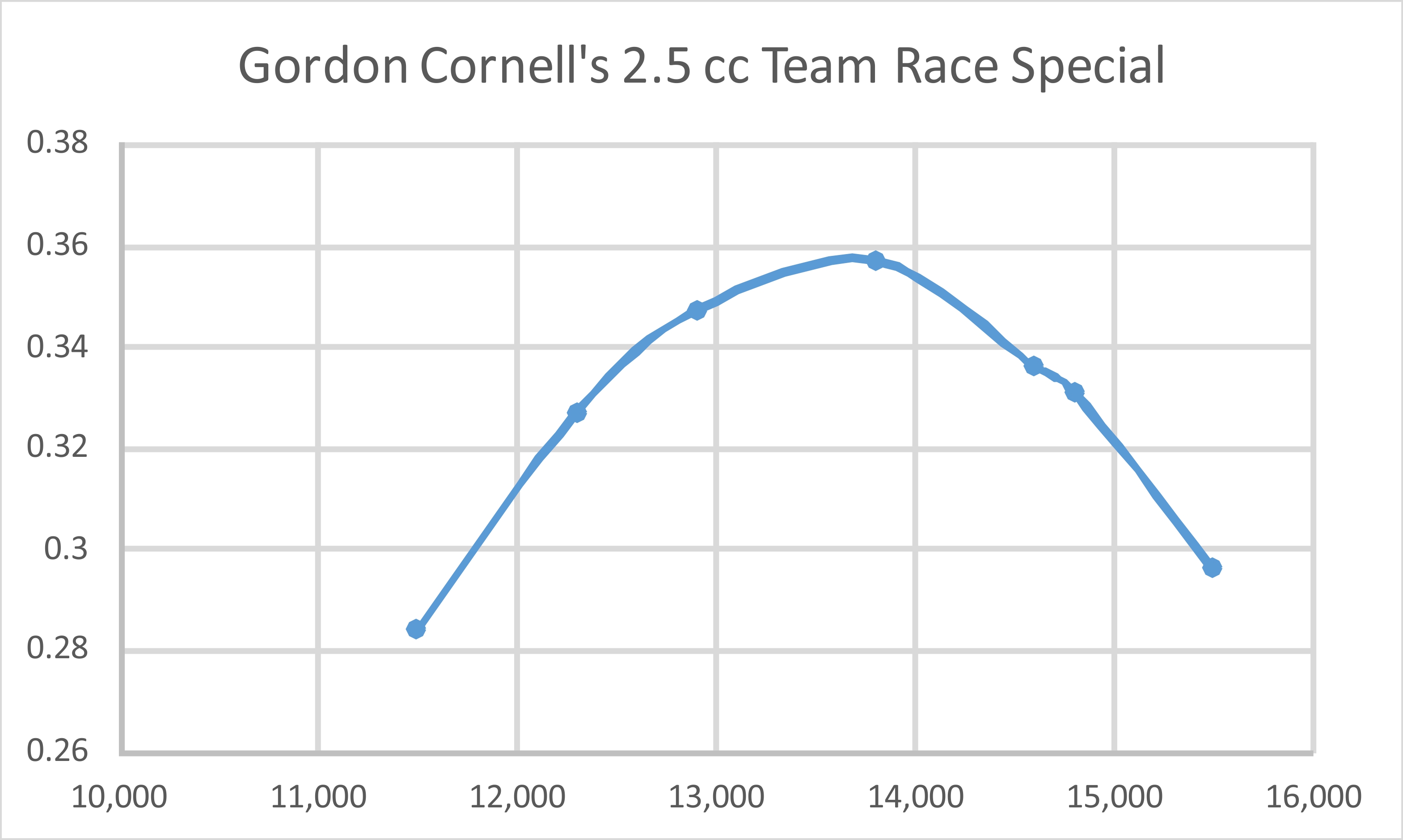
As can be seen, the engine delivered an exceptionally high peak power output by 1960 standards, topping out at around 0.360 BHP. Moreover, it hit this peak at the relatively modest speed of only 14,000 rpm. This comparatively low peaking speed is attributable to the relatively short exhaust and transfer periods, which were clearly aimed at generating higher than average torque as oppposed to a high peaking speed. The relatively "slow" fuel that I used also doubtless held the engine back a little - it would almost certainly beat these figures on a more potent blend. I reckon that the engine could potentially develop arond 0.365 BHP @ 14,500 rpm as configured for the test. The use of a smaller-diameter spraybar would also doubtless improve performance quite noticeably. As it is, this result with a relatively conservative set-up must be seen as a tribute to Gordon Cornell's skill as a model engine designer, since the engine delivers outstanding torque and above-average power at a relatively moderate speed - just what the doctor ordered for the team race event where the ability to swing a reasonably-sized prop with some "bite" was so important. Typical team race props in use at the time were 7x8 or 7x9 items. The TR 247 seemingly has the grunt to turn a 7x9 at or near its very considerable peak in the air. The time-honored formula for potential model airspeed is: Airspeed (mph) = RPM x Pitch (inches) 1320 Using this formula, we find that a 9 inch pitch prop turning at 14,500 rpm could yield an airspeed of around 98.8 mph. In reality, I'd expect somewhat less than this because airscrew efficiency decreases with decreasing diameters. However, a pretty good airborne performance by the standards of 1960 is undoubtedy indicated. Fuel consumption might be the Joker in the pack ............... The only contemporary 2.5 cc diesel engines of my own direct experience that could top this output were my Super Tigre G.30-D and my Rivers Silver Streak Mk. I, both of which were quite capably tuned. Moreover, both of them had to run somewhat faster to achieve their maximum outputs. The TR 247 came through this test with flying colours. No mechanical issues of any kind were encountered - indeed, the engine appeared willing to keep on doing this all day. So once again, well done, Gordon Cornell! He designed and constructed a 2.5 cc team race diesel of exceptional quality and performance. It's too bad that circumstances prevented E.D. from taking this design forward to the production stage. If they had done so, we might have seen the E.D. name return to the top of the competition heap! In fairness to Gordon, I must record the fact that following the initial publication of this article he contacted me to express his opinion that the admittedly rather "slow" fuel that was used for this test had compromised the engine's performance unduly. He recommended the use of a fuel containing 50% kerosene, 30% ether 20% castor oil and no more than 2% IPN or similar. In support of his advice, he asserted that this very engine had turned a FROG nylon 7x6 prop at 18,500 rpm during his own tests back in the day. The old FROG nylon 7x6 was a rather "fast" prop which is pretty much equivalent to a modern APC 7x5. As the above data show, I only saw 15,500 rpm on that prop. With the greatest respect to Gordon, I simply can't see the suggested fuel change adding 3,000 rpm to the TR 247's speed on that prop. To turn an APC 7x5 at 18,500 rpm would require the development of around 0.50 BHP at that speed - a very tall order by 1960 standards, especially with radial cylinder porting. Mind you, the engine as tested by me had a very conservative spraybar/venturi combination fitted. A switch to a 2.5 mm diameter spraybar would increase the effective choke area to 16.314 mm2, increasing the practical minimum operating speed on suction to 13,457 rpm. I suspected that the engine would run a bit faster with such a set-up, particularly with the faster props. Even so, I have trouble envisioning the TR 247 getting that APC 7x5 prop up to 18,500 rpm........... In fact, I eventually gave this a try, switching to a spraybar having a 0.120 in. diameter (3.05 mm) and a fuel blended to Gordon's specifications. There was a definite improvement - the APC 7½x4 WB prop now hit 14,100 rpm, while the 8x4 got up to 14,900 rpm. However, the 7x5 spun at 15,700 rpm, up a little but still well shy of Gordon's claim. The 7½x4 figure implies that the output is now up to around 0.370 BHP @ 14,100 rpm - an outstanding performance for a 1960 radially-ported diesel. Gordon can be truly proud of his effort! The Aftermath
In addition to bringing the Super Fury and the revised Bee to the production stage, Gordon did receive authorization to complete the development work on his 3.5 cc drum valve diesel, albeit in marine form only. The result was the previously-mentioned Sea Otter, one of the all-time great marine model diesels. This was to remain a steady seller for E.D. and its successor companies over many years. Sales continue to this day (2020) through Alan Greenfield’s Weston UK company, 60 years on. In an effort to pull the company out of its increasingly precarious financial condition, E.D. management began casting about somewhat desperately for new product lines. Gordon recalled that they were approached by the Ministry of Defence to manufacture small diesel-powered generators for lifeboats – Ministry staff evidently did not appreciate the fact that E.D. “diesel” engines were not true diesels! Given the fact that E.D. did not have the financial capacity to undertake such a project, Gordon was unable to support E.D.'s further consideration of this program.
Taking advantage of Gordon's growing disillusionment with the deteriorating situation at E.D., Alan persuaded Gordon to leave E.D. to join his company, Dydesyne Ltd. of Slough in Buckinghamshire, to design and produce what became Gordon’s legendary 0.81 cc Dynamic .049 twin ball-race diesel. This wonderful little unit undoubtedly drew much of its design inspiration from Gordon’s earlier TR 247, utilizing the same centrifugal drum valve arrangement allied to radial Oliver-style cylinder porting and a twin ball-race crankshaft. Gordon had proposed a basically similar model to E.D. management as an alternative to the highly problematic Pep, but they were unwilling to abandon the investment which the Pep represented, warts and all. It’s a sobering thought that if E.D. management had shown themselves to be a little more forward-thinking at the outset before the Pep fiasco got started in 1959, the Dynamic .049 could have been released in early 1960 as the E.D. .049 BB! It would have sold like hot cakes ………………
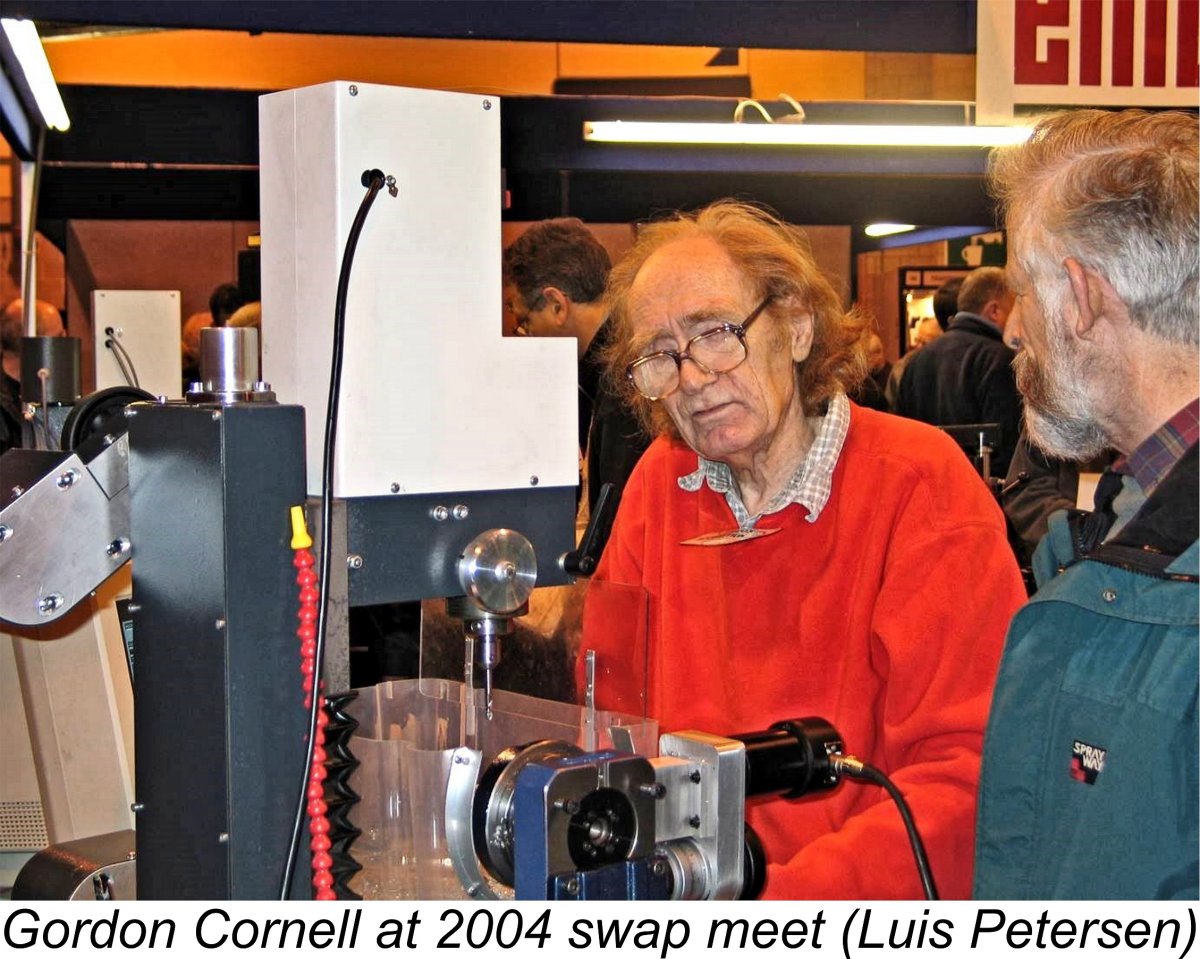
Gordon was initially forced to take up employment at Vickers in Weybridge, but eventually returned to his pre-E.D. employment working for Dodge Brothers (Britain) Ltd. By an ironic twist of fate, Alan Dye later ended up working for Gordon at Dodge Brothers, thus reversing their former positions! Naturally enough, Gordon couldn’t stay away from model engines for ever! He later got back into model engine manufacture in a relatively small way, producing a limited number of superb engines under the Dynamic label, of which he had assumed ownership. He also continued development work on his best-known design, the Super Fury. But that’s another story which has been ably told elsewhere by Gordon himself Gordon was never reluctant to embrace new technology, becoming an expert user of computer-controlled CNC machinery in later years. He is shown in Luis Petersen's attached image demonstrating his CNC Wabeco milling machine at a swap meet in 2004. His stand at that meeting included an impressive display of a number of his latter-day engines. My last-ever contact with Gordon came in 2020 when I was preparing this article. Although 88 years old by then and with somewhat compromised eyesight, he was still hard at work developing an advanced 1.5 cc design. This had involved getting up to speed on 3D machining, which Gordon described as "a massive learning curve". His latest iron-and-steel 1.5 cc models were developing around 0.35 BHP without any form of exhaust extension. There was apparently some interest in putting this design into service as a tether car powerplant. I'd guess that it would probably do quite well in that application! Sadly, Gordon passed away in March 2021, taking with him an amazing amount of knowledge and expertise relating to the wonderful world of model engines. Conclusion I hope that you’ve enjoyed this evaluation of another Gordon Cornell masterpiece - his TR 247 team race diesel. The more I come to know about Gordon’s various model engine designs, the greater my respect for him becomes. He must surely be recognized as one of England’s most talented and prolific model engine designers of them all! It's a great pity that his talents were so relatively under-utilized by the mainstream British model engine manufacturing industry. A full review and test of Gordon's Dynamic .049 and its Tutor companion will appear on this website in due course. __________________________ Article © Adrian C. Duncan, Coquitlam, British Columbia, Canada First published May 2020
|
||
 In a separate article to be found elsewhere on this website, I’ve presented a review and test of the outstanding one-off
  The problem facing Gordon was that the E.D. model engine range had stagnated for some years, hence steadily losing ground to the more advanced designs then emerging from other manufacturers. Some E.D. models were over ten years old by the time in question. Consequently, Gordon quickly realized that the entire E.D. model engine range urgently required upgrading or replacement. However, this had to be done in a highly compressed time-frame and on a limited development budget in order to satisfy the demands of the company’s bankers.
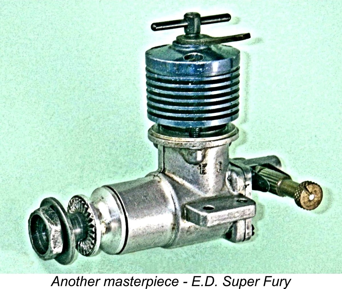
 instead with the job of sorting out the dog's breakfast into which the Pep program had evolved. Quite apart from his natural frustration at having been called in after the fact, Gordon was not best pleased to learn that the new model was to bear his own nickname of “Pep”!
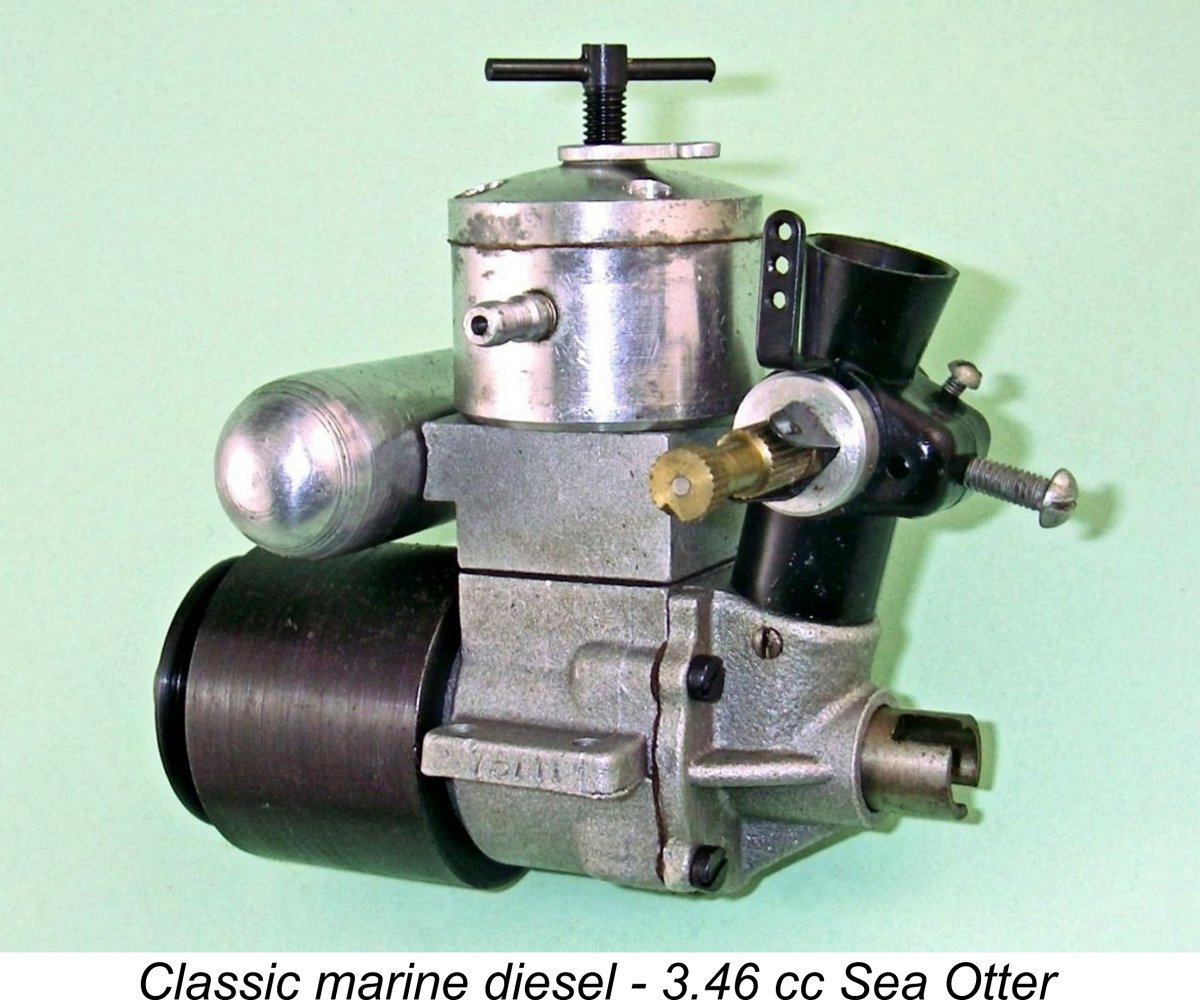
 Gordon had retained his active interest in control line team racing throughout this period. This led him to evaluate a few potential replacement designs for the now-aging but still popular
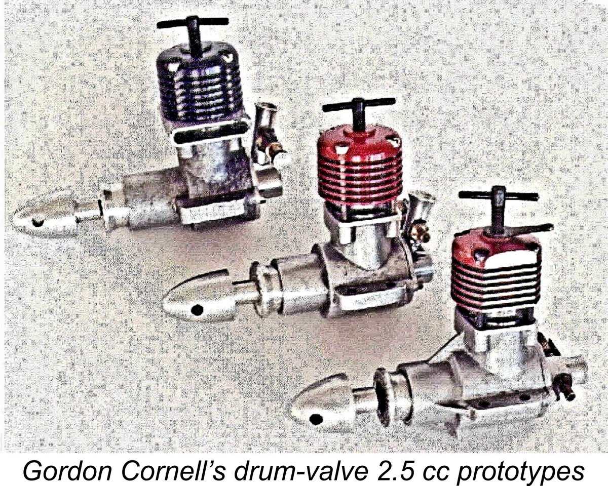
 controlling gas access from the (usually) downdraft venturi into the internal gas passage in the drum and thence to the crankcase interior. Because the drum does not have to do double duty by transmitting the engine’s torque in addition to controlling the induction, the designer can take far greater liberties in terms of internal gas passage diameter, induction port size and induction timing.
 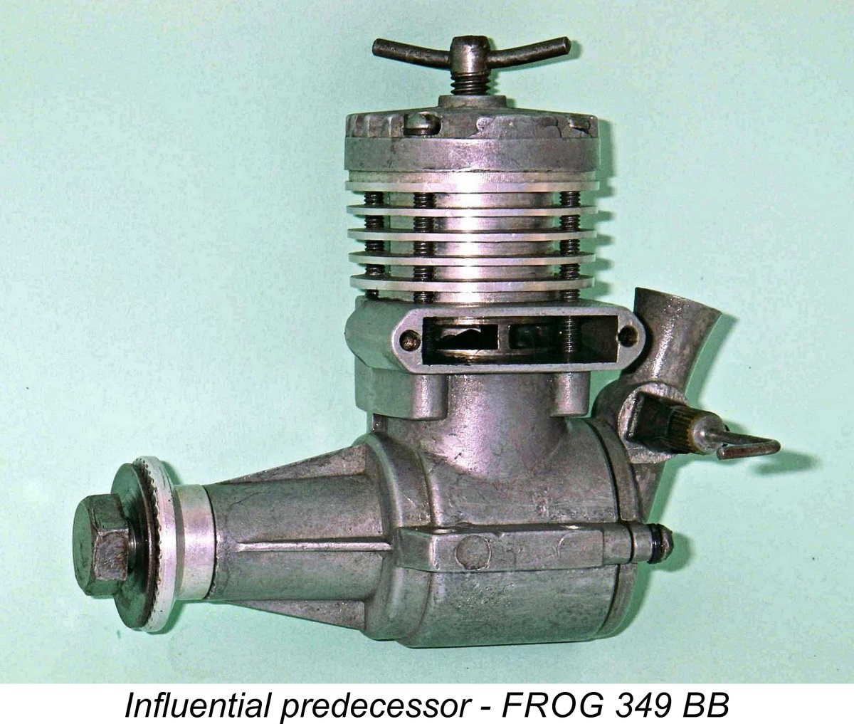 The previously-mentioned FROG 349 was not the first model engine to utilize this arrangement, but it was certainly one of the best-recognized commercial models of this type and was undoubtedly instrumental in showing the way. The design worked very well in the FROG, although the engine’s weight and bulk told against it for competition applications. Still, the dear old
 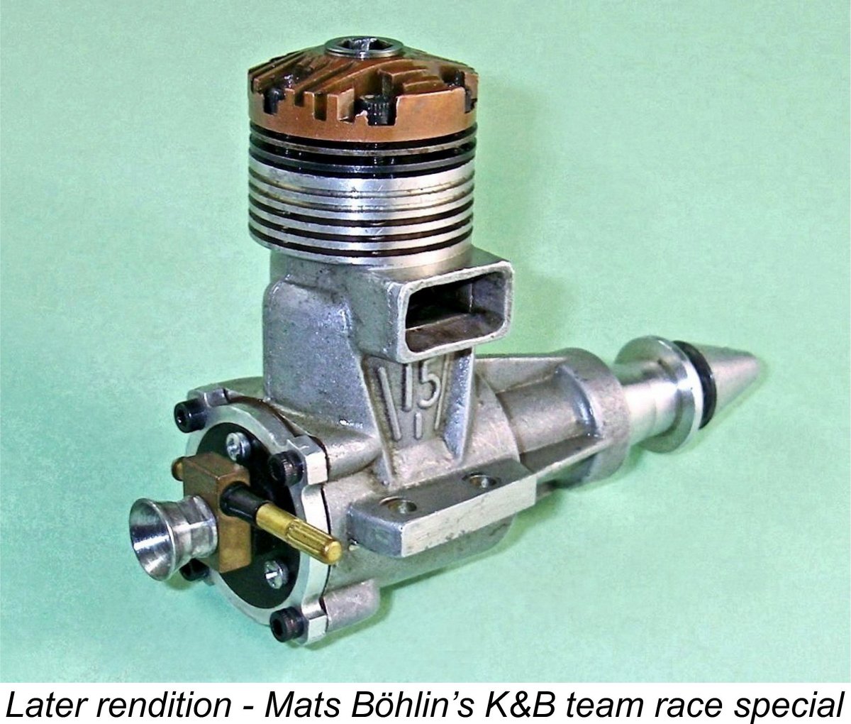 1970's. The previously-reviewed K&B-based
 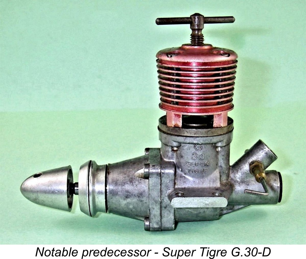 In many respects, the TR 247 is a conventional competition diesel of its day, utilizing reverse-flow scavenging based upon well-developed Oliver-style cylinder porting along with a twin ball-race crankshaft. Its use of drum valve induction was by no means unique either - Super Tigre designer Jaures Garofali had previously used this design approach in both his 2.5 cc G.30-D and 1.5 cc G.31 competition diesels of 1957 as well as the companion 1 cc G.32 model, while the
 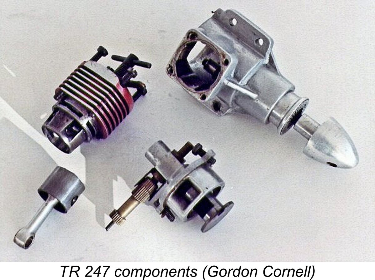 The two conventional drum valve models used a case on which the main bearing housing was unbraced. The case used on the subject TR 247 engine was modified by having four bracing webs added to the main bearing, presumably to enhance stiffness. It also featured a set of quite deep longitudinal cooling fins on the base of the crankcase, evidently to improve cooling of that component.
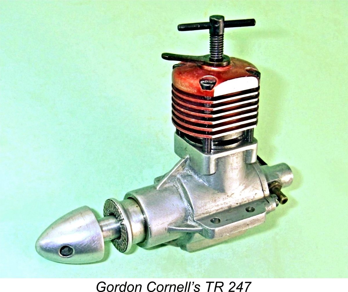 Port timing is actually relatively conservative for a “racing” engine, presumably reflecting the engine’s intended team race application in which the most efficient use of fuel is so important. In that discipline, tunng for high power at high revs could be counter-productive because that combination tends to use a lot of fuel at high speeds with the type of cylinder porting used, with which short-circuiting of incoming mixture straight out the exhausts becomes an issue. Besides, power doesn't come from nowhere! We might expect an experienced team race engine designer like Gordon to go after high power at mid-range speeds.
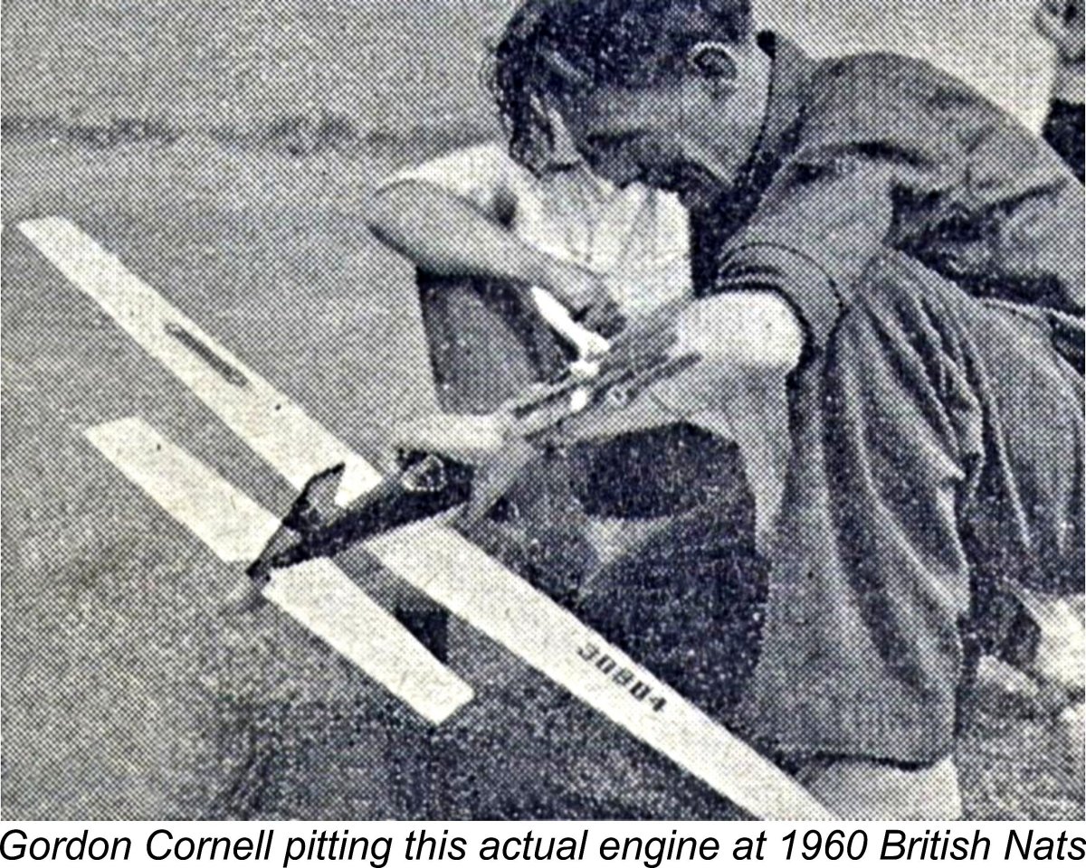 frontal area in typical team race fashion. This is the only one of the three to be modified in this way, reflecting the fact that it was the only one actually used by Gordon in competition.
 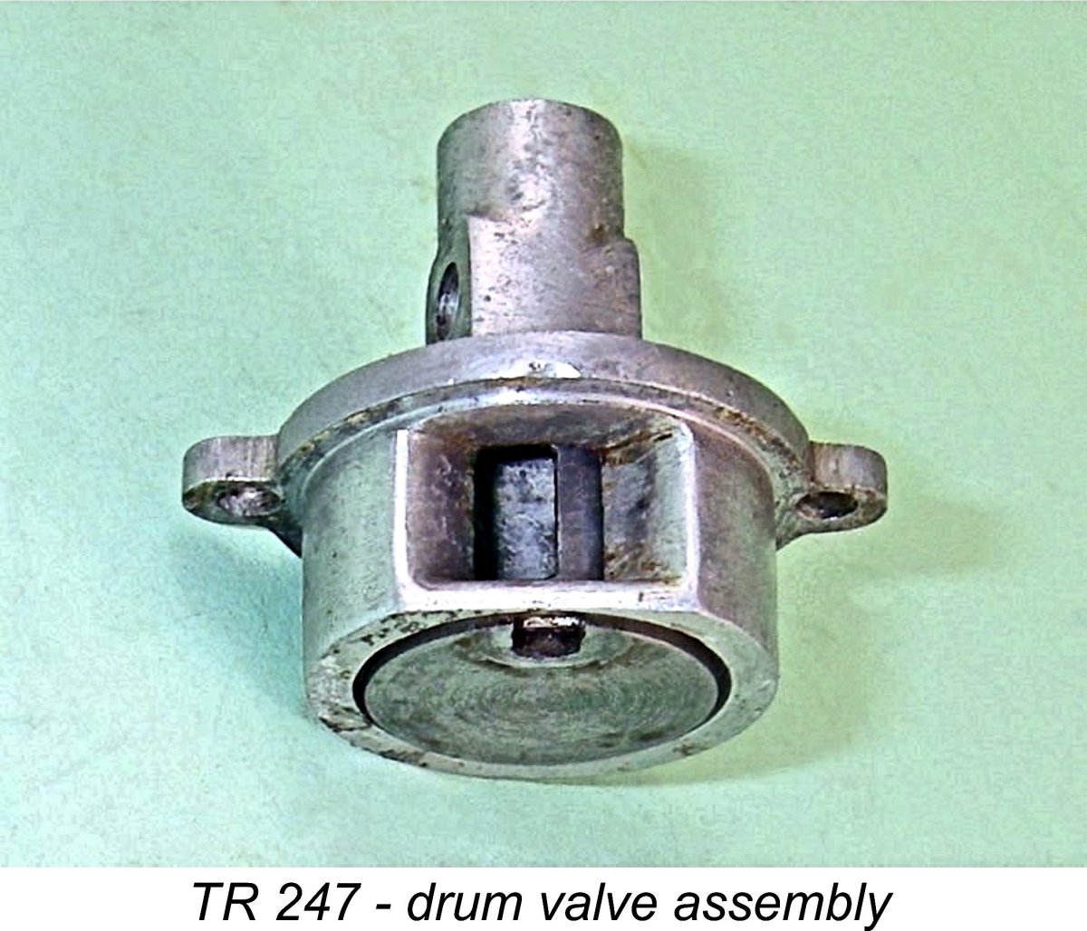 The drum has an internal diameter of 0.250 in. (6.35 mm) which is exactly matched by the venturi throat. The induction timing provided by this assembly is quite aggressive - the valve opens at 45 degrees after bottom dead centre (ABDC) and closes at 45 degrees ATDC for a very “racy” total induction period of 180 degrees. This is considerably more than could have been achieved with a conventional FRV arrangement without unduly compromising crankshaft strength - a significant concern at the time, as we have seen.
 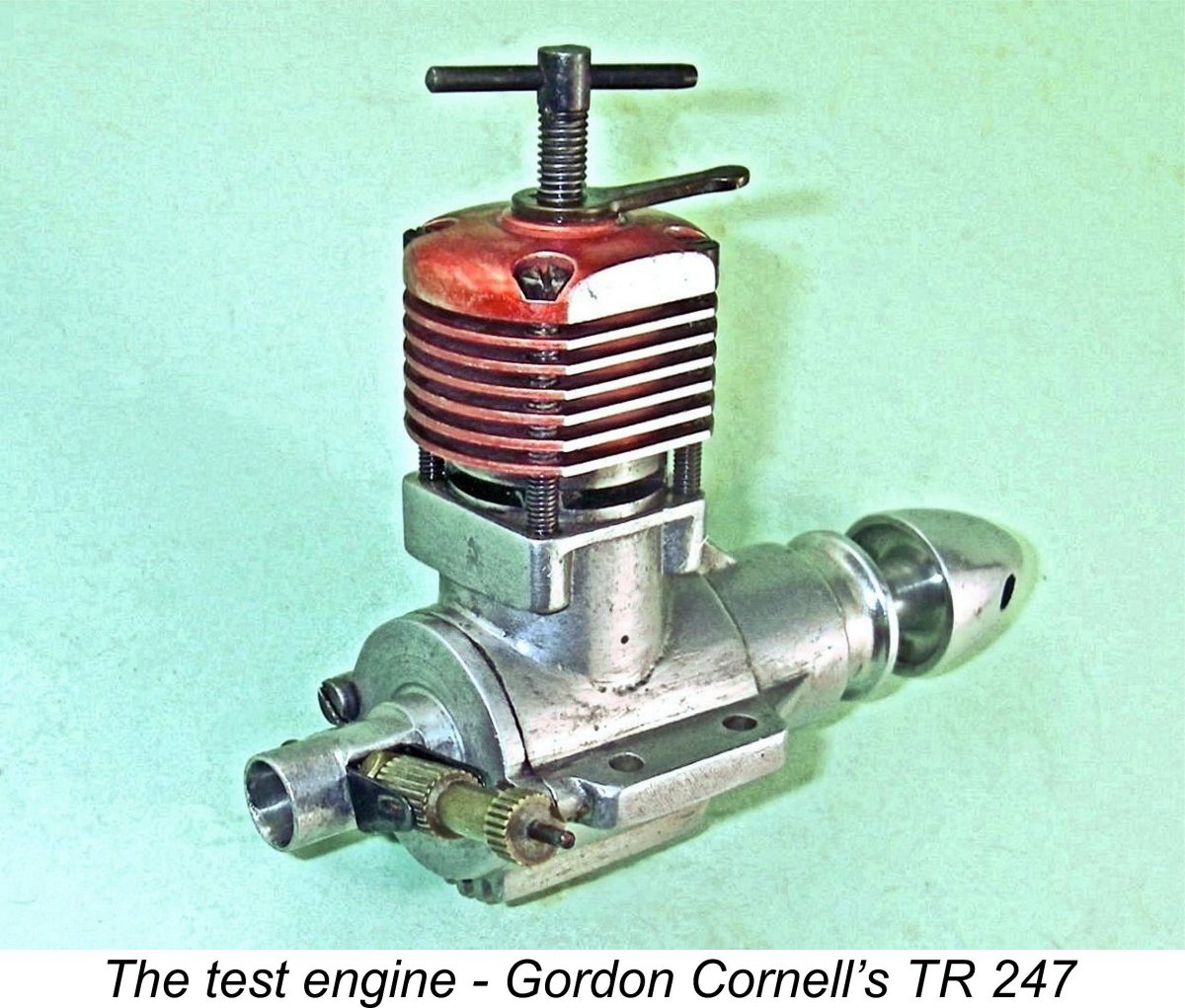 Recalling the truly amazing performance measured for Gordon’s
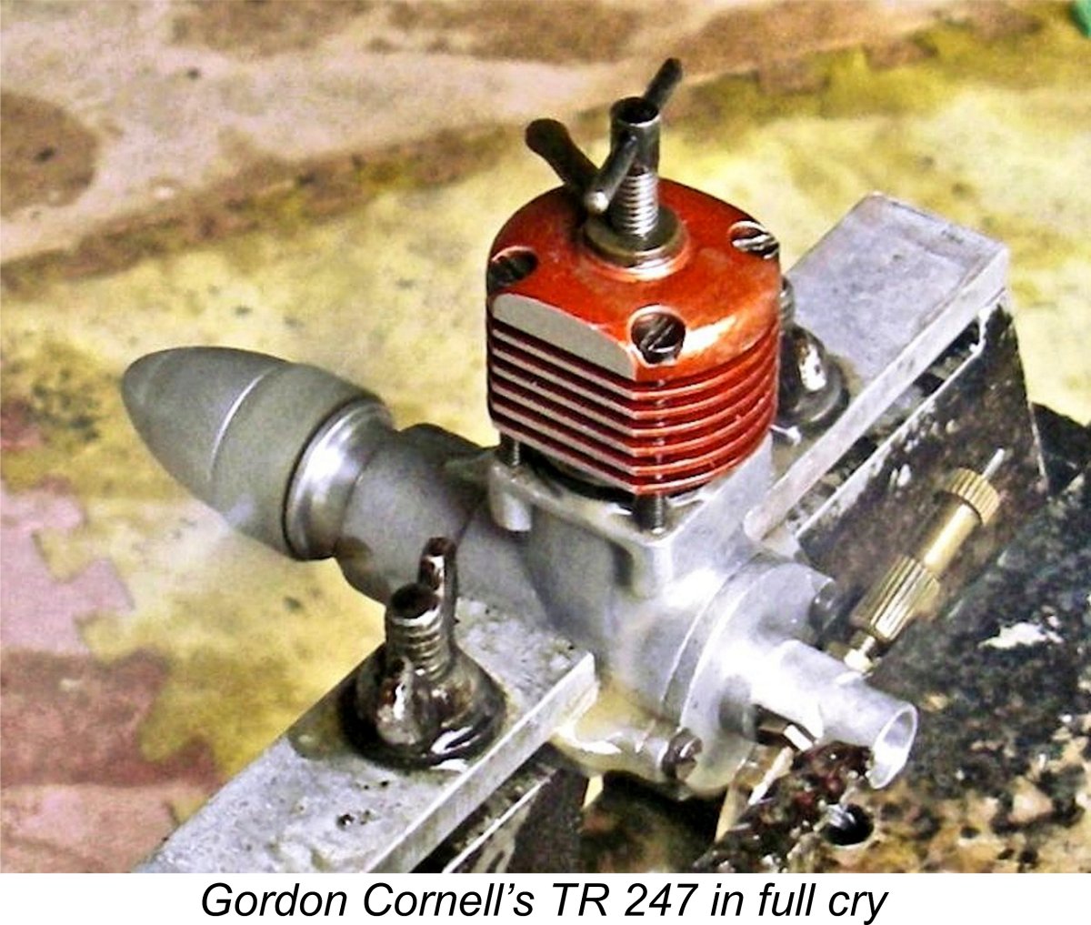
 It should now be quite clear that Gordon’s TR 247 design was a very competitive powerplant indeed, being well able to challenge the leading 2.5 cc competition diesels of the day in terms of sheer performance. However, it would have been relatively expensive to bring to the production stage. Gordon showed it to E.D. management, who were duly impressed but were unable to support its further development into a production model due to the previously-noted fiscal constraints under which they were then operating. The Pep fiasco had done nothing to alleviate this situation, leaving E.D. with no choice other than to direct Gordon’s attention back to the re-development of existing models. Consequently, the very promising TR 247 was consigned to aeromodelling history along with the equally impressive TR 148.
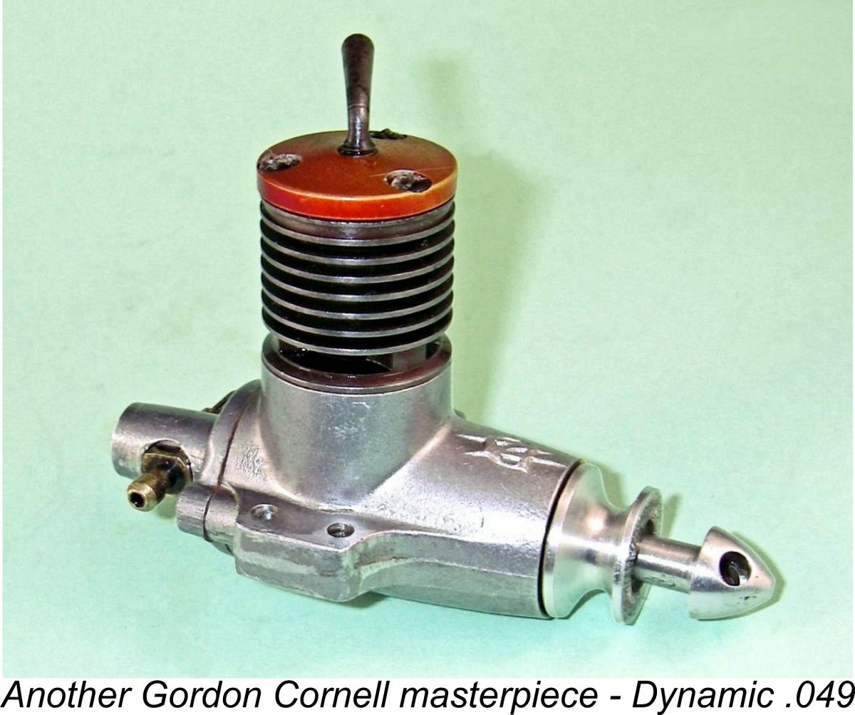
| |