
|
|
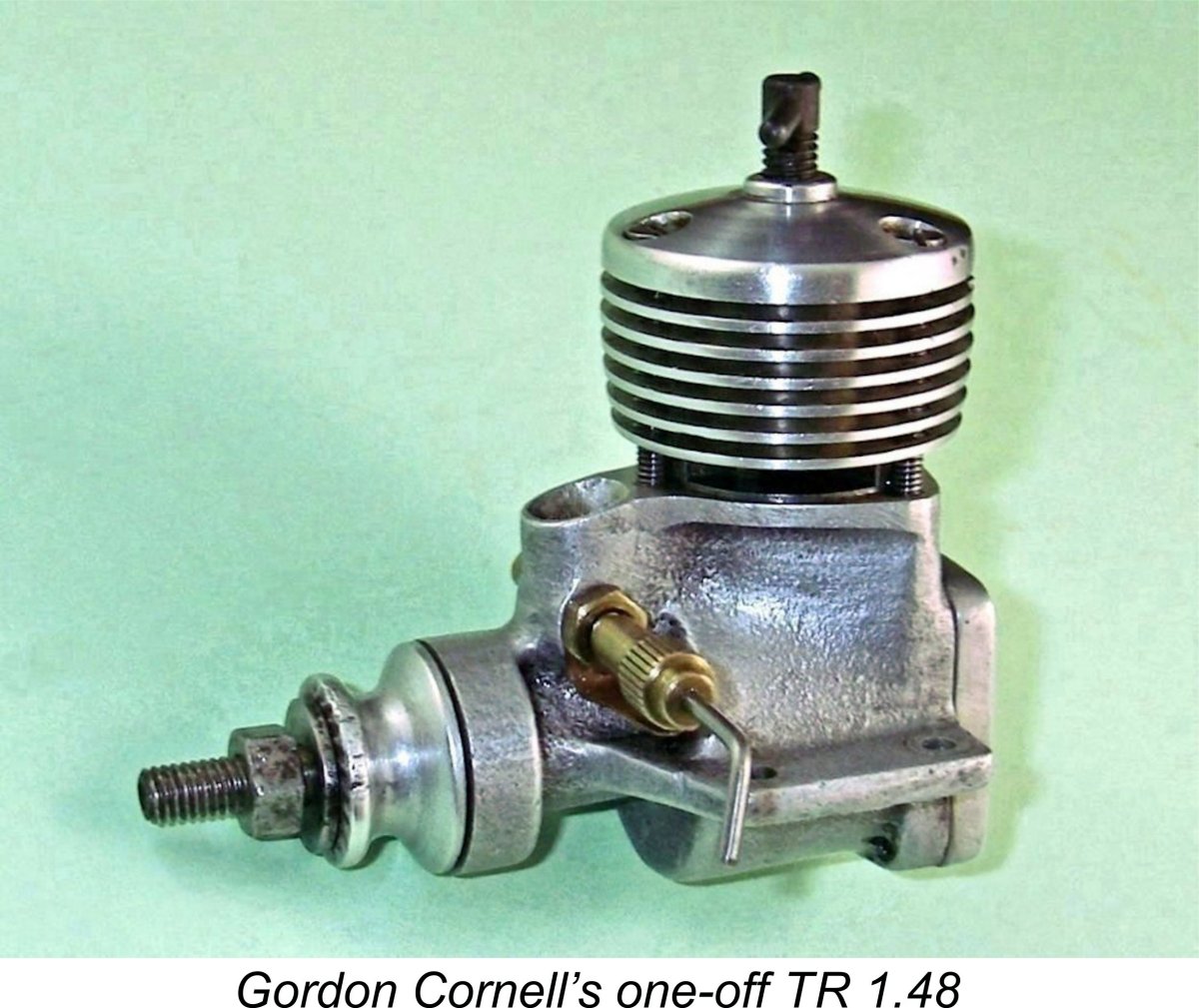
Another Gordon Cornell Masterpiece – the TR 148 Diesel
This is another of my series of articles on model engines which undoubtedly existed in prototype form but which never actually made it into production. Other examples have included the Thermite, AHC and DeLong diesels from America as well as the ETA 15 glow-plug design from England. The justification for publishing details of such engines, original examples of which will almost never become available to collectors, is their significance in the historical context of model engine development, very much including the light that they shed upon their designers and manufacturers. This is another such instance. The writing of this article was made possible solely due to Gordon Cornell’s kindness in drawing my attention to the fact that the only example of his TR 148 ever made was on offer on eBay. Happily I was able to win the auction, thus making this historic and unique one-off engine available for inspection, testing and sharing. My very sincere thanks to Gordon! Gordon was also most generous in sharing his personal recollections of his own life and career leading up to the creation of the TR 148 and beyond, including the provision of a number of "period" photographs. He also read and corrected the first two drafts of this article. We’re all in Gordon’s debt for his kindness in this regard. I freely admit that even with the engine itself in hand I could not even have begun this project without the benefit of Gordon’s invaluable assistance. Quite apart from the documentation of the TR 148 project, this article also provides a welcome opportunity to provide a summary of Gordon’s early career as a model engine designer up to the point at which he became the chief engineer for E.D. Such a tribute is long overdue. Let’s get right down to it! Gordon Cornell’s Early Career
Gordon began with Round-the-Pole (RTP) models, winning his first ever event in 1946 while still only 13 years old flying a Ron Warring “Spook” RTP model. He received a plaque which had been made by Mr. Headitch, the school woodwork teacher (generally known as “Scratchy” for obvious reasons!). Scratchy was himself an aeromodeller who had also made his own model diesel engine. This sparked off Gordon’s lifelong fascination with model powerplants. Gordon’s paper round paid for his first engine, a Mills 1.3. He soon graduated to control-line and other disciplines. He recalled meeting the others quite regularly on Epsom Downs, where they were tutored by a then-prominent Wakefield flier, a certain Mr. Pitcher, whose first name was never used by the respectful Juniors!
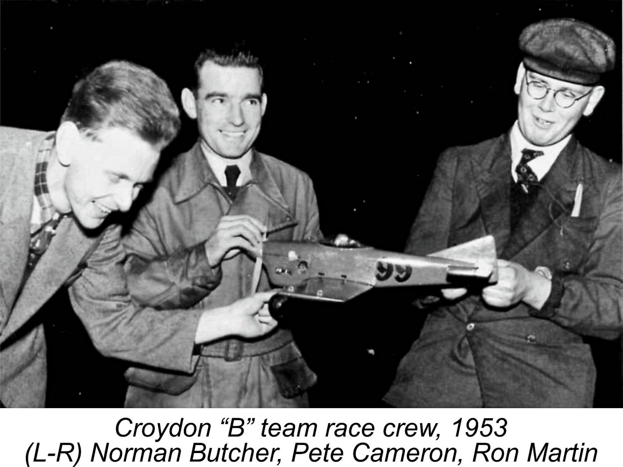
However, Gordon’s ongoing activities with the two clubs were comprehensively disrupted by National Service from 1951 to 1954. Gordon spent just over 2 years in Germany as a member of the Royal Air Force at RAF Oldenburg, near Bremen. Following demobilization in 1954, Gordon got married. His two elder children were born in 1955 and 1957. Gordon found employment working in the automotive engineering field for Dodge Brothers (Britain) Ltd., the Kew-based British subsidiary of Dodge Bros. of America. His transportation at the time consisted of a motorcycle and sidecar combination, Gordon’s school friend and fellow Carshalton Club member Peter Nye had also been demobilized at about the same time. The two naturally re-connected as civilians, and in 1957 Peter took Gordon to a major model flying meeting at Woburn Abbey near Milton Keynes in Bedfordshire, the home of the Duke of Bedford. This was the event at which Howard Bonner and Bob Palmer gave demonstrations in R/C and control-line stunt respectively as part of an international tour. The event was reported in the July 1957 issues of both “Aeromodeller” and “Model Aircraft”. At that meeting, Gordon distinguished himself by winning the C/L combat event flying a model powered by an Allen-Mercury (A-M) 35 diesel (that’s 3.5 cc or 0.21 cuin. for our American readers!). At the time, C/L combat was flown in Britain under Society of Model Aeronautical Engineers (S.M.A.E.) rules, which allowed Gordon’s prize for winning this event was a brand-new 1.49 cc Taifun Hurrikan diesel from West Germany. Fellow members of the Croydon Club celebrated Gordon’s win in style, particularly since he had been absent from the contest scene for some years due to his period of National Service as well as his growing family obligations. Of even greater significance to our story, it was at this meeting that Gordon first encountered George Fletcher. At the time, George was the chief engine designer for International Model Aircraft (IMA), whose FROG range of engines was deservedly popular among British sport fliers. Prior to taking up this position, George had worked successively for Davies-Charlton (D-C) Ltd. and Allbon Engineering in the model engine field. He had replaced Bert Judge as IMA’s chief engine designer in 1951 after Bert departed to join Wilmot, Mansour & Co. in pursuing the development of their Jetex range. Gordon couldn't recall if George introduced himself at the event or at the subsequent club meeting/celebration. Regardless, this meeting came at a pivotal point in George’s career with IMA. The FROG engines up to that point had all been budget-priced sports types having relatively modest levels of performance. However, performance was becoming an increasingly important factor affecting sales, even in the sports categories. IMA’s parent company, the Lines Brothers organization, had taken note of this situation, resulting in a request from Graham Lines that George set about upgrading the FROG range to make On the basis of the Woburn Abbey result, George became aware of the above-average control-line flying capabilities of both Gordon and his fellow club-mate Norman Butcher (Editor of “Model Aircraft” at the time). Since control-line flying was then the most popular form of aeromodelling in Britain (how times change!), also representing the most significant performance and durability challenge for any model engine with its long continuous flat-out runs, George suggested that Gordon and Norman should come on board as a test team to assist in the further development of the FROG engines and model kits. This suited Gordon very well indeed, since he and George were actually near-neighbours. George was then living in a flat at Morden only about 2 miles from Gordon’s home and a mile or so from the IMA factory, which was co-located with the main Triang Works plant at Merton. Since his workplace was within easy walking distance, George routinely walked to work – he did not even own a car at the time.
At first the test team travelled everywhere in Gordon’s car (which had by then replaced the sidecar combination). Somehow, they managed to accommodate their wives and Gordon’s children in the back seat – sardines, anyone?!? Fortunately, Norman Butcher had his own car, at one point a Riley Kestrel, which eased the transportation problem somewhat. At a later date, the team was granted the use of the FROG van.
Gordon also built stunt models for both the FROG 500 and FROG 150 to serve as test beds in the evaluation of those engines. At the time in question IMA had found themselves holding a significant stock of unsold FROG 500 glow-plug models which they naturally wished to dispose of in order to recover the tied-up capital which they represented. These incorporated the ball thrust race whichhad been added to that design in 1955. However, that modification had proved to be unsuccessful for a number of reasons, as detailed in Gordon did some work on the old 500, finding that the removal of the lower half of the piston skirt on the transfer side released a significant amount of extra power as a result of the reduced obstruction of the entry to the bypass passage as well as the lightening of the piston. However, as far as can now be determined, this modification was never incorporated into the production engines – as far as IMA were concerned, the FROG 500 had reached the end of its commercial road. A pity – it could easily have been applied retroactively to existing stocks, which might have increased their saleability. I tried this modification myself independently many years ago, with similar findings to those recorded by Gordon. The testing of Bert Judge’s old 1.49 cc FROG 150 (dating originally from mid 1951) demonstrated that, despite a few The principal motivation behind the development of the ½A events in Britain was to make both combat and team racing more widely accessible by reducing the associated costs. The required investments in engines and models were significantly lower than with the larger-displacement classes, while operating expenditures (fuel, etc.) were also reduced. In addition, smaller flying areas could be used. Gordon soon began to take an interest in the emerging ½A team race category, powering his first ½A team racer with the Taifun Hurrikan which had been his prize from the Woburn Abbey event.
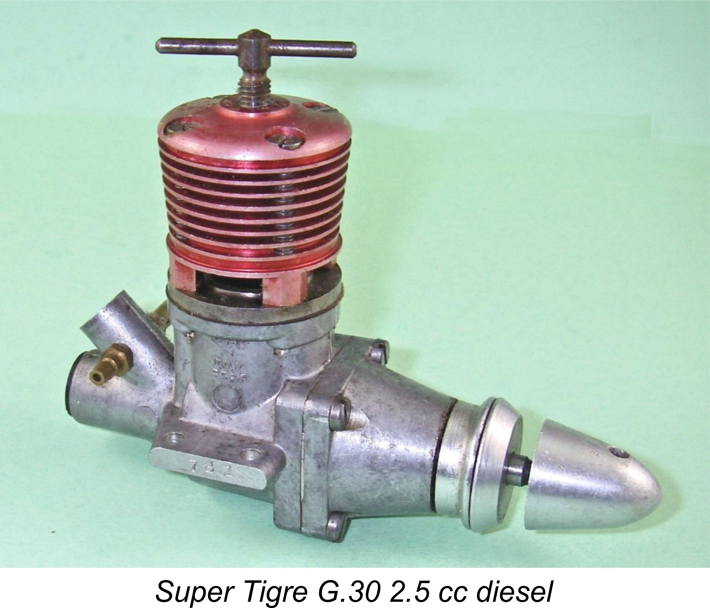
Following a few ”incidents” arising from this cause, Gordon decided that such engines were totally unsuitable for use in a racing environment where pit stops were required. He became convinced that rotary valve induction was the only way to go, hence his steadfast adherence to various forms of that system when planning his later designs. Gordon’s involvement with IMA’s development programs soon expanded from flight testing into the engine design field. One of his most significant achievements while with IMA was his development of the FROG 150R, a significantly upgraded While Gordon was thus occupied, the IMA directors had become keen on the idea of developing a larger engine that might compete for sales in the developing R/C market both for model aircraft and model boats. Accordingly, George Fletcher had begun to consider the development of a 3.5 cc unit to expand the FROG range. A significant motivation for the choice of a 3.5 cc displacement stemmed from the previously-noted fact that the British combat rules then in effect allowed the use of engines of up to 3.5 cc displacement. The selection of a displacement of 3.5 cc could thus considerably broaden the sales potential of the engine. Having made that decision, the next question facing George was what kind of induction systen to use. At the time, the 2.5 cc competition diesel category was bedevilled by a rash of crankshaft failures as Accordingly, George suggested that the IMA design team should develop a 3.5 cc engine with a rear drum valve, a feature which had then recently been employed successfully in its conventional form by Super Tigre in Italy. This arrangement had the great advantage of not requiring any induction porting in the working crankshaft, thus significantly increasing its durability for a given size. However, the conventional Super Tigre drum valve design was not adopted – instead, the decision was taken to employ an “inside-out” version of the drum valve in which the interior of the drum was open to the atmosphere rather than to the crankcase – the reverse of the usual shaft/drum rotary valve arrangement. Gordon used the very apt term “centrifugal drum valve” to describe such an arrangement, which he was to employ to very good effect in a number of his later designs. It's worth noting in passing that the centrifugal drum valve arrangement gained widespread favour among constructors of team race engines, probably peaking in the mid-1970's. However, at that time it had become recognized that the oil content in the fuel contributed nothing to range since it did not burn. Accordingly, the oil content in team race fuels was then steadily decreasing, generally falling below 15% (today, team race oil contents of 5-10% are not unusual). It was soon found that the centrifugal drum valve system had a tendency both to starve the conrod big end bearing of oil and to fall short of providing sufficient cooling for that bearing. Engines using the system did not do well on low oil-content fuels. However, the new FROG was expected to run on commercial fuels having a far more "normal" oil content. Its use in the FROG 349 was therefore no barrier to the engine's reliability, as my own countless hours of enjoyable flying with these engines have amply demonstrated.
Of course, all of these concepts had individually appeared earlier in other British designs. However, the combination of these features in a large diesel was well out of the rut in the context of the 1958 British marketplace. Such a combination in a single design may have been a step too far, particularly in view of the very compressed development time-frame which was imposed upon George by IMA management. George also hung a millstone round his own neck in design terms by electing (or perhaps being directed) to tailor the The best engine of the lot using the FROG nylon 9x6 prop was actually Gordon’s trusty Woburn-winning A-M 35, which matched the FROG 349 by turning the FROG nylon 9x6 prop at 11,000 RPM while also being far lighter – engine weight was becoming increasingly recognized as a significant factor affecting the aerobatic performance of a Another factor affecting the engine’s performance in this event was the very significant gyroscopic effect of the heavy 9x6 airscrew, an aerobatic factor which was only just beginning to be appreciated. Of course, other competing engines were not affected by any artificial prop criteria. Most people used 8x6 props on their Olivers, which turned those props in the air at sufficiently high speeds to yield significantly higher outputs than those attainable by either the FROG 349 or the A-M 35. In addition, the Mk. III Oliver weighed considerably less than the FROG 349, although it outweighed the A-M 35 by a substantial margin.
Had more time been available, there’s little doubt that the 349 could have been developed into a really competitive engine. My own experience with self-tuned examples has amply proved the potential of the concept – a well-tuned FROG 349 is a very impressive engine indeed! George’s problem was that he simply didn’t have the time or human resources required to fully exploit the engine’s design features through a focused development program. It was the shortfall in human resources which had led him to seek the involvement of Gordon and his fellow Croydon club members. While all this was going on, Gordon continued his own model flying and testing activities. His interest in ½A team racing remained strong despite his lack of success with that initial Taifun Hurrikan-powered model. That experience had convinced him that rotary valve induction was the only way to go when it came to the development of team race powerplants. Gordon’s previously-noted success in developing the old FROG 150 into the far more powerful FROG 150R was the first step along his road towards the development of an engine suitable for ½A team racing. The FROG 150R proved to be a top performer among mass-produced 1.5 cc diesels of its era, developing 0.152 BHP @ 14,500 RPM according to Peter Chinn’s test of that model which appeared in the July 1958 issue of “Model Aircraft”. Considerably more power could be released through tuning, as both Gordon and I have independently demonstrated.
Accordingly, in 1958 Gordon began working on the design of a proposed high-performance twin ball-race companion to the FROG 150R. The twin ball-race FRV unit which he envisioned was aimed squarely at the ½A team race event which was continuing to gain popularity, to the point that it was finally added to the British National Championship schedule in 1960. It was Gordon’s personal interest in this category that led him to pursue the development of a competitive engine for the class. The development of a truly competitive ½A team race engine gained momentum when Gordon’s clubmate Peter Frazer expressed an interest in becoming actively involved in ½A team racing. Gordon quickly produced a design, after which the first (and as events turned out, only) TR 148 was made in Stewart Frazer’s machine shop behind Pride & Clarke’s Motor Cycle shop in Stockwell.
It should be recalled that British ½A team racing was still very much in the developmental stage as a competitive class at this time – people were still learning. The prevailing theory was that models needed to be small in order to achieve the best possible speeds in the air. However, this made them extremely difficult to handle both during take-off and landing on grass. In particular, the pit man’s task was rendered almost impossible due to the very high landing speeds. Wooden propellers were frequently broken, while plastic or nylon ones in most cases lacked efficiency. Nonetheless, “Jumbo Junior” and the TR 148 did see some competition action. Gordon served throughout as his own pit man, while the piloting duties were taken on by Peter Frazer. Although they did not win any contests, the team proved that the TR 148 was at least a match for the Oliver Tiger Cub Mk. 1 and other competing ½A team race engines of the day. In performance terms, it was unquestionably a front-runner, its main drawback being a somewhat higher than ideal rate of fuel consumption. It should be recalled that all of the Oliver Tiger Cubs were in fact individually-constructed “specials”, so the playing field was level. At this point, fate took a hand in the game. During the latter part of 1958, George Fletcher received a letter from Jim Donald, then Managing Director of the competing Electronic Developments (E.D.) company, requesting that Fletcher consider joining them to fill the gap left by the final departure of Basil Miles from his role as E.D.’s chief engine design consultant. George did not wish to leave IMA at that time, suggesting instead that Gordon Cornell contact Jim Donald. Gordon was quite happy to do so, resulting in an offer from E.D. Accordingly, in late 1958 Gordon took up the position of chief engineer for E.D. One thing that changed very much for the better as a result of this move was Gordon’s access to manufacturing facilities. As chief engineer he enjoyed the full use of the E.D. factory facilities at West Molesey for his future development work. By this time, Gordon's energetic approach to his activities had earned him the nickname of "Pep"!
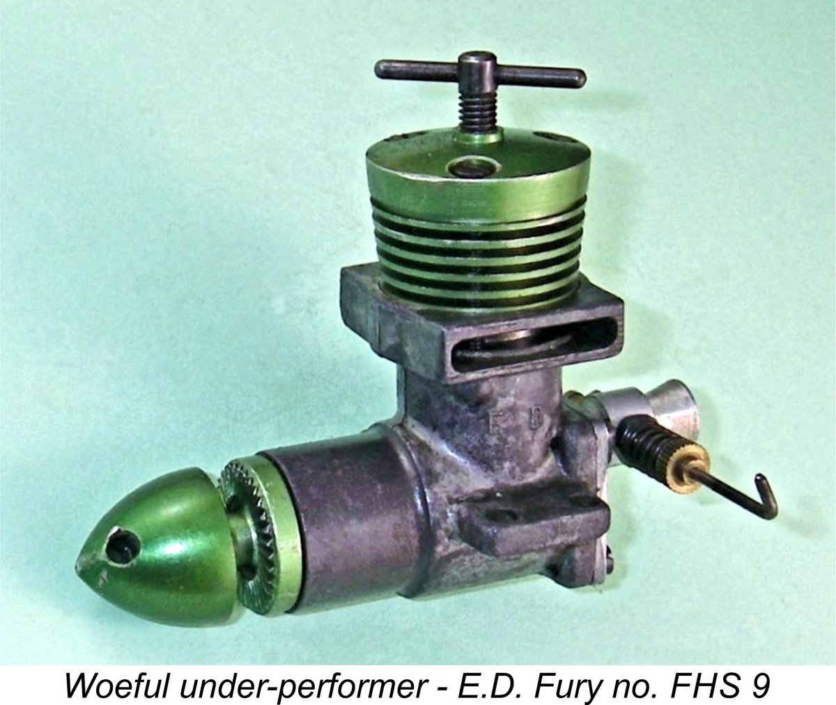
It was clear from Gordon’s earlier testing that the TR 148 prototype could serve as the basis for a very successful production model. E.D. management were certainly impressed – in fact, E.D.’s Managing Director Jim Donald went so far as to ask Gordon to look into the possible production of this model by E.D.. However, this request came at a time when Gordon had been reviewing the entire E.D. model engine range, just as he had done earlier with the FROG engines. This review left Gordon in a bit of a dilemma - how do you tell the largest model engine manufacturer in the UK that all of the company’s products need replacement in short order?!? To add to the difficulties, E.D. was in an increasingly shaky financial situation at the time, having been asked by their bank managers to present a definite plan to reduce the sizeable overdraft which had been created as part of the fall-out from the infamous Purchase Tax case of late 1950, of which much more in other articles on this site. Jim Donald passed this responsibility wholesale to Gordon. The problem facing Gordon was that while the entire E.D. model engine range urgently required upgrading or replacement, this had to be done in a highly compressed time-frame and on a limited development budget in order to satisfy the demands of the company’s bankers. As Gordon saw it, the development of an all-new production model based on his TR 148 would require more time and development resources than he had at his disposal, to say nothing of the associated need for a whole new set of costly dies and tooling. Moreover, although it had shown outstanding levels of performance, the TR 148 was still a basically unproven design, never having won a contest. E.D. simply could not afford another costly failure like the E.D. Fury which had promised so much and delivered so little. However, they were to get such a failure regardless in the shape of their ill-conceived 1960 E.D. Pep with which they chose not to involve Gordon until the project was past saving. That rather sad story has been recounted in detail elsewhere. As matters stood in 1959, it was clear to Gordon that the upgrading of the E.D. range would have to be approached through the incorporation of improvements into the company’s existing designs rather than through the development of all-new models. Sadly, this consigned Gordon’s very promising TR 148 prototype to the sidelines and thence to model engine history. Having come to this realization, Gordon initially focused his attention upon the reconfiguration of the lacklustre reed valve E.D. Fury. The existing dies and tooling for that model provided convenient options to develop disc valve and drum valve prototypes relatively quickly and at minimal cost – just what the situation demanded. Gordon’s various experimental Fury-based models were flight-tested in a series of larger and hence better-handling ½A models called the “Leveret”, which appeared in Mk. I, Mk. II and Mk. III versions. “Leveret I” had a low wing with dihedral and a lifting wing section to aid take-off. “Leveret II” featured a shoulder wing location and proved to be a most satisfactory model. With “Leveret II” it was found possible to exceed the flight performance of Oliver Tiger Cub-powered models, even though extra pit stops were required due to the higher fuel consumption necessary to achieve such levels of performance.
Gordon’s tests proved that a tuned E.D. Super Fury could produce up to 14,500 RPM on a Frog 7x6 nylon propeller. On a Tornado 6x8 Plasticote prop, it generated 12,800 RPM. Using such a prop, it was found that speeds of up to 100 mph could be achieved in flight, albeit at higher than optimum fuel consumption. The competing Oliver Tiger Cub was typically fitted with a 6x9 prop, resulting in a somewhat lower speed (70-80 mph) but with significantly better fuel economy. The higher speeds and speed differentials then being attained in the ½A event actually began to create significant difficulties with heats involving 4 pilots flying models which flew at a wide range of speeds in the range of 70-100 mph on the relatively short lines used in ½A team racing. This issue actually led to changes being made in the model rules for the class. The updated “Leveret III” model was built to address these rule changes. Thankfully, Gordon took the trouble to set out a very comprehensive record of the development program which led to the creation of the Super Fury. This account may still be found on Ron Chernich's "Model Engine News" (MEN) website. Well worth reading! Gordon’s further adventures in the model engine design field have been recounted in my separate articles on the E.D. range in general and the E.D. Pep in particular. For now, I’ll focus on an in-depth evaluation of the still-born TR 148 model. What kind of an engine was E.D. forced to pass up due to their financial woes?!? Let’s have a look! The TR 148 Diesel Described
The TR 148 retained the same bore and stroke as Gordon’s earlier FROG 150R model. Bore and stroke measurements were 0.500 in. (12.70 mm) and 0.460 in. (11.68 mm) respectively for a displacement of 1.48 cc (0.090 cuin.). The engine weighed a quite respectable 121 gm (4.27 ounces) – exactly the same as both the E.D. Super Fury which appeared in early 1960 and the Oliver Tiger Cub Mk. 2 which was to join the fun in late 1960. It appears that Gordon took advantage of the ready availability of FROG 150R components when he was planning the TR 148 prototype. The very short-skirted piston appears to be a FROG 150R component, as does the forged con-rod. It’s possible that the shaft was a modified 150R component as well, although my reluctance to disturb what appeared to be a superbly-fitted and clearly well settled bottom end prevented me from confirming this. That said, it would have been very logical for Gordon to use as many readily-available components as possible when planning this self-constructed prototype model.
The form of porting employed is of course made possible by the fact that the cylinder is a drop-in item rather than following the screw-in arrangement used in the 150R. Hence the cylinder can be aligned as necessary prior to being tightened down. It is retained by a machined slip-on light alloy cooling jacket which is secured using three 6 BA machine screws. The outside diameter of the exhaust port belt which locates the cylinder vertically in the case is such that clearance channels had to be hand-filed in it between the exhaust ports to provide clearance for the Cylinder port timing is very consistent with the engine’s intended purpose as a team race unit. The exhaust opens at 110 degrees after top dead centre for a total exhaust period of 140 degrees, while the transfer ports open only some 4 degrees later for a total transfer period of around 132 degrees. The engine’s most noteworthy feature in this regard is the truly massive amount of sub-piston induction – some 90 degrees in total (45 degrees either side of top dead centre). This is an even more extreme application of sub-piston induction than that applied by Gordon to the earlier FROG 150R, which had a total sub-piston induction period of around 80 degrees. The use of this amount of sub-piston induction implies that the assigned role of the FRV induction system was largely confined to the introduction of sufficient fuel mixture into the crankcase – the sub-piston induction was expected to make up for any shortfall in the amount of air induced. This view is confirmed by the fact that while the FRV system opens at 40 degrees after bottom dead centre, it closes only 10 degrees after top dead centre for a total period of 150 degrees.
The above discussion leads to the conclusion that the FRV system was expected to have more or less completed its fuel-inducting function by the time the sub-piston induction opened at 45 degrees before top dead centre. A completely logical design approach - given the massive area of the sub-piston induction porting, there was nothing to be gained by keeping the FRV system open simultaneously. In any event, the overall induction period for such a system is a combination of the FRV and sub-piston induction periods. Taking both systems into account, the engine was in its induction cycle from 40 degrees after bottom dead centre (when the FRV system opened) to 45 degrees after top dead centre (when the sub-piston induction system closed). The resulting total induction period of 185 degrees would do credit to any racing engine of the period.
Gordon informed me that the engine was originally fitted with a FROG needle valve assembly. The needle valve assembly on the engine as received was an Oliver component, which was presumably added by a later owner. However, the Oliver set-up is basically very similar to the original FROG assembly. Perhaps the most relevant overall comment is the quality of the engine’s construction, which is up to the very highest standards in all respects. The ball-races used were clearly of very high quality – the engine feels absolutely superb when turned over. Compression seal remains near-perfect, with no trace of “stiction” at any point in the stroke apart from a very slight (and highly desirable) pinch at top dead centre. Gordon commented that while he was quite happy with the engine’s performance, he felt that the necessarily large inner ball-race made the engine both excessively heavy and bulky. He also had his previously-mentioned doubts regarding the crankshaft diameter. If development of this model had proceeded further, both of these issues would doubtless have been addressed. Despite these reservations on the part of the engine’s designer, this initial prototype is clearly a very competent effort which does full credit to Gordon Cornell’s abilities. How does it run? Let’s find out! The TR 148 on Test
In the present instance, it was necessary to head into the realm of might-have been in order to select a few suitable bench-marks. Fortunately, a number of such bench-marks leap out as soon as one starts thinking about this issue. First, there’s the FROG 150R. It was his work with this engine which started Gordon down the 1.5 cc development road. Moreover, it seems to have influenced a number of features of the TR 148. A record of the improvement achieved by Gordon with his TR 148 prototype would clearly be of interest. Published figures for the 150R were readily available.
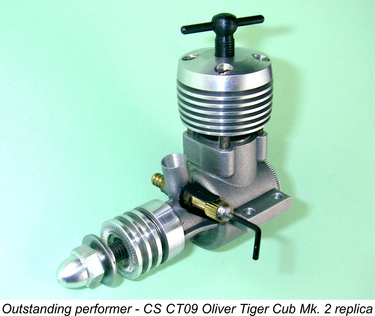
Finally, there’s the “contest that never was”! There’s absolutely no doubt that the TR 148 would have handily outperformed the Oliver Tiger Mk. 1 – indeed, Gordon’s competition experiences confirmed this. However, if the engine had entered production as an E.D. competition model, it would quickly have come up against the improved Oliver Tiger Cub Mk. 2. How would it have fared?? Once more, I had ample data on hand against which to draw a valid comparison. At the time when I was planning to test the TR 148, my part of Western Canada was hit by a particularly severe series of winter storms. This prevented me from getting to grips with the engine for quite a while. Accordingly, Miles and I shared the pleasure of testing this engine together. We headed out to the Richmond flying site of my own club, the Vancouver Gas Model Club (now in its 90th year of existence!) on a cold and overcast day. Having set the TR 148 up in the test stand, we proceeded to give it a shake-down run using an APC 8x4 prop. The fuel used was my usual mix containing 42% kerosene, 30% ether and 28% castor oil, to which was added a further 2½% ignition improver. The engine proved to be an excellent starter despite Response to both controls was found to be excellent. The contra-piston was perfectly fitted, as a result of which the compression screw held its settings firmly at all times. The Oliver needle valve assembly provided very accurate fuel metering as well. Consequently the engine’s optimum running settings were very easily established and held. Having got the engine nicely settled down after its long layoff, we proceeded to run a set of calibrated test props. It quickly became apparent that this was no ordinary “classic” 1.5 cc diesel – the levels of performance that we were measuring were well above the average for a 1.5 cc diesel of this era. The following figures speak for themselves.
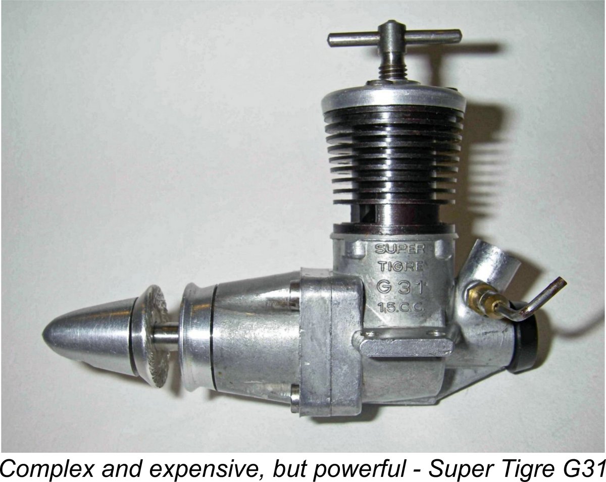
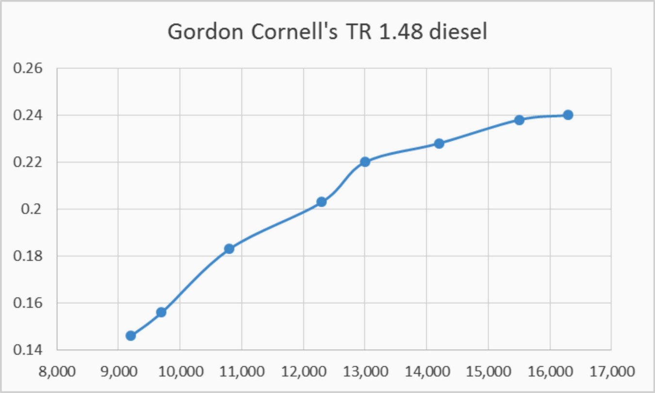
The APC 8x4 WB prop listed above is a cut-down APC 9x4 created and calibrated by myself to fill a gap in the range of available power absorption coefficients in my test set. Looks like we just missed the best setting on the APC 8x4......... The smallest prop tested was the Cox 6x4 fibreglass item, which is one of the fattest and therefore slowest 6x4 props ever manufactured. I had assumed that this prop would take the engine past its peak, but in fact it appears that the TR 148 was right at its peaking speed of around 16,300 RPM using that prop! At that speed, the engine was developing around 0.240 BHP. Since the power curve had flattened out anyway at that point, I elected not to risk damage by pushing the engine further. Needless to say, the measured figures of 0.240 BHP @ 16,300 RPM represent a quite remarkable performance for a 1958 radially-ported 1.5 cc diesel of basically “classic” design. To check out the comparative models listed earlier, the 1958 FROG 150R developed 0.152 BHP @ 14,500 RPM based on Peter Chinn’s test. The E.D. Super Fury as originally released in early 1960 was found to develop around 0.170 BHP @ 14,500 RPM based upon tests by both Ron Warring and Peter Chinn. Other well-known 1.5 cc contest diesels of the period recorded similar figures. The drum-valve Super Tiger G.31 of 1957 had led the way by developing 0.16 BHP @ 16,000 RPM based on the results of Peter Chinn’s November 1957 test. The PAW 149 of 1959 was found to develop over 0.170 BHP at a speed in excess of 16,000 RPM – an outstanding figure for a plain-bearing diesel of the period, but still nowhere near the TR 148. The later FROG Viper (another drum-valve design) of 1961 was found to develop 0.162 BHP @ 15,700 RPM. It was not until mid 1962 that 1.5 cc diesel performances began to creep up past the 0.200 BHP And what of the Oliver Tiger Mk. 2 which appeared in late 1960? Well, published test figures for that engine revealed a typical output of around 0.18 BHP @ 15,000 RPM as delivered. My own test for “AeroModeller” magazine of a tuned example of the CS replica of the Mk. 2 Oliver Tiger Cub (a remarkably accurate and well-made copy) demonstrated a potential of around 0.220 BHP @ 15,000 RPM. The important thing to be derived from all of this is that the TR 148 outperformed all of the cited competing models which were available as of 1959-60, and by a very wide margin at that. It was not until 1962 that the performances of other engines in tuned form, such as the E.D. Super Fury and the Oliver Tiger Cub Mk. 2, began to approach the performance of the TR Miles and I did note one factor during our test of the TR 148 that might well have adversely affected its performance as a team-race engine. Performance does not come from nowhere – you have to burn fuel to generate power. We observed during the test that the TR 148 seemed to be quite thirsty, requiring frequent refills of a rather large tank. While the engine’s ability to absorb fuel and use it effectively clearly contributed much to its performance, there was evidently a price to be paid for that performance in terms of increased fuel consumption and hence a greater number of pit stops. Gordon actually recalled that while the TR 148 model was very fast, it did require extra pit stops which affected its competitiveness. Still, a most impressive achievement by Gordon Cornell! Considering that this is a one-off prototype which therefore represents only the initial stage of development, this must be considered to be a truly remarkable 1.5 cc diesel! Conclusion Elsewhere I have documented some of Gordon’s further activities as a model engine designer. Notable among these activities were a series of drum-valve models developed during 1960 while working for E.D. These included the deservedly-famous Sea Otter 3.46 cc marine diesel as well as a very powerful 3.5 cc drum valve aero diesel prototype. There was also a series of 2.5 cc drum valve models which were intended as possible replacements for the aging E.D. Racer. An examination and test of the most successful of the latter models appears elsewhere on this website. A detailed examination of the remarkable .049 diesel models developed by Gordon for Dyedesyne after leaving E.D at the end of 1960 will also appear here in due course. Meanwhile, I hope that you’ve enjoyed this detailed examination of one of the most remarkable 1.5 cc diesels to appear anywhere during the 1950’s. Too bad that the engine was never developed further! ________________________ Article © Adrian C. Duncan, Coquitlam, BC, Canada First published September 2017
|
||
 Here I’ll take a close-up look at yet another “model engine that nearly was” - the TR 148, which was a one-off product of one of England’s most prominent and respected model engine designers of the “classic” and post-classic eras, the late Gordon Cornell. Designed and constructed in 1958 when Gordon was 26 years old, this unique engine was briefly considered for production by
 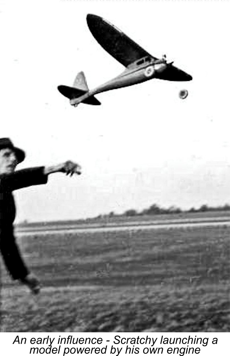 Born in September 1932, Gordon Cornell began his long and distinguished aeromodelling career as a teenager in the South London area. He attended his first Croydon Model Club meeting at the age of 13 in late 1945 at a school hall in East Croydon, subsequently becoming an active member of the Croydon club. He was one of three model flying-obsessed juniors who joined the club at that time, the others being Norman Marcus and Ed Bennett, both familiar names to modellers from the “classic” era in Britain.
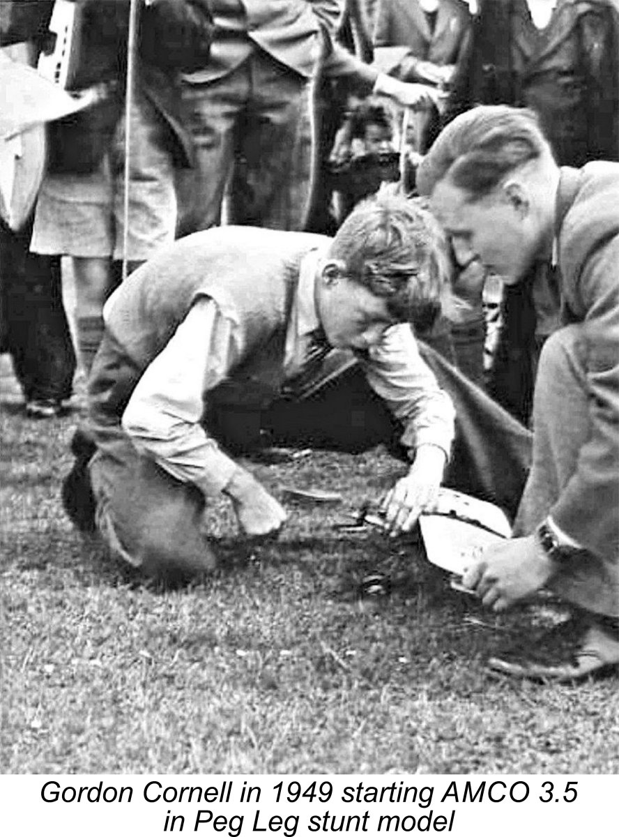 Between 1946 and 1948, Gordon attended Wimbledon Technical College, travelling there daily by train or bicycle. While maintaining his membership in the Croydon Club, he also joined the Carshalton Club whose members flew control-line in nearby Beddington Park. It was during this period that Pete Cameron of the Carshalton Club taught Gordon to fly control-line.
 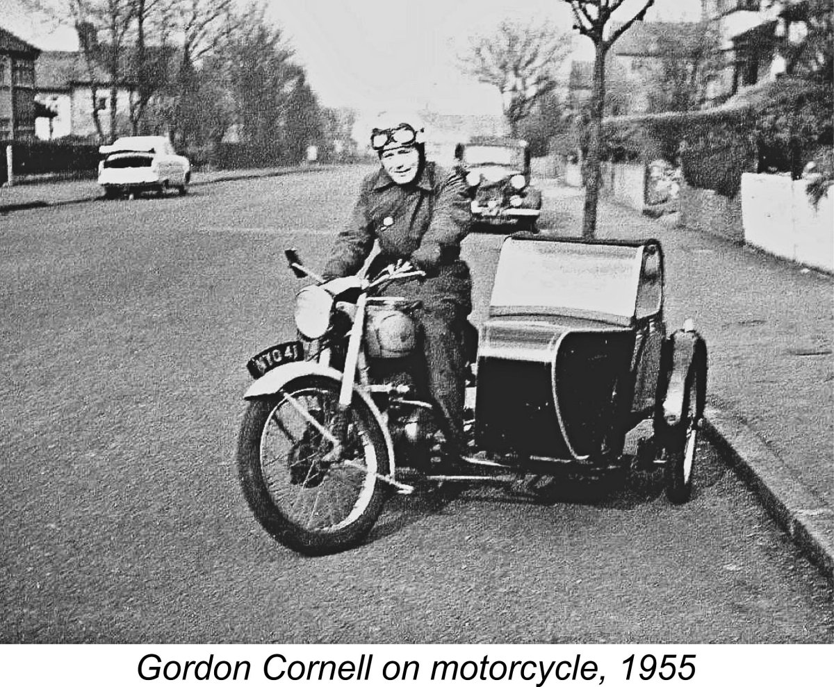 which he later replaced with a car. During the same period, he resumed contact with his friends at the Croydon and Carshalton clubs.
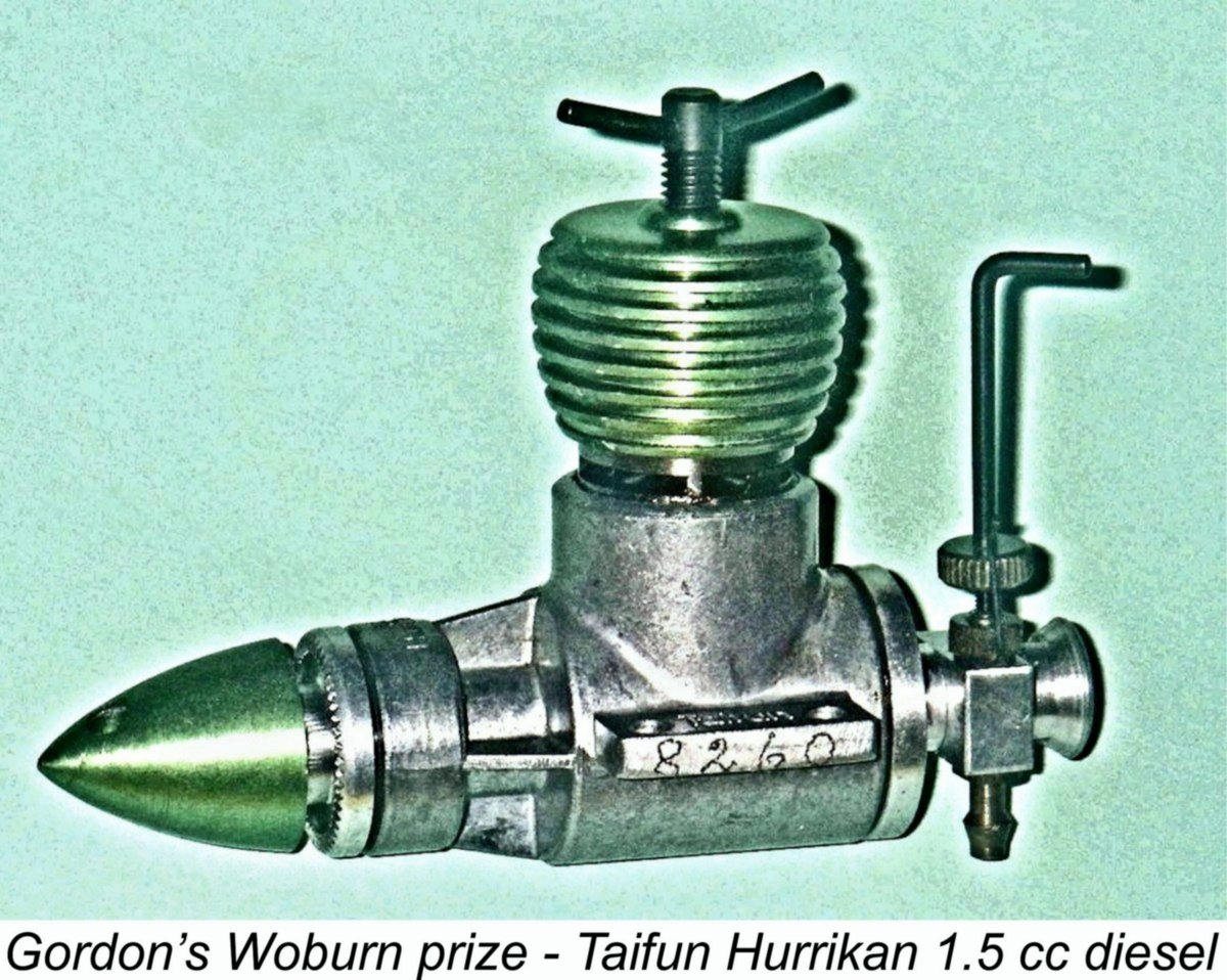
 the engines competitive with those of other competing UK manufacturers.
 Once the new development team was established, a flight-testing program involving both engines and models was initiated using the Lines Bros. sport field which was part of the factory complex. This field may be seen to the right of the main factory complex in the accompanying air photograph. Gordon recalled that factory visits occurred on most Saturday’s. Additional flight testing took place in Beddington Park and on Wimbledon Common close to the Windmill Pub (an inducement, perhaps?!?).
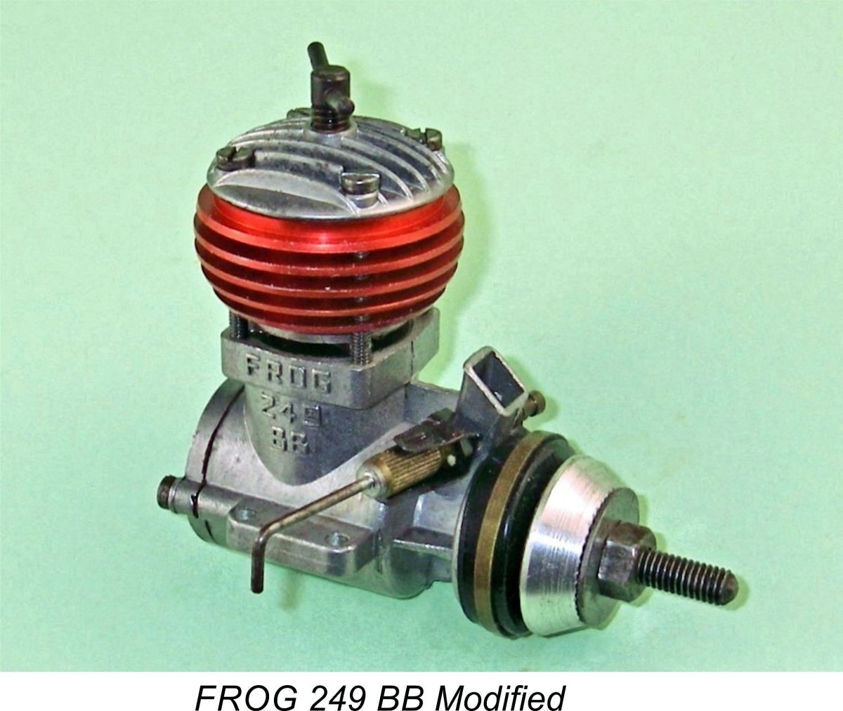 A review of the FROG engine line-up was quickly undertaken. Gordon recalls fitting an example of the newly-developed FROG 249 BB Modified into his combat model, but it proved to be inferior to the A-M 35 used previously. Although no less an authority than Peter Chinn characterized it as “the most powerful quantity-built 2.5 cc diesel made in Great Britain at the present time” (
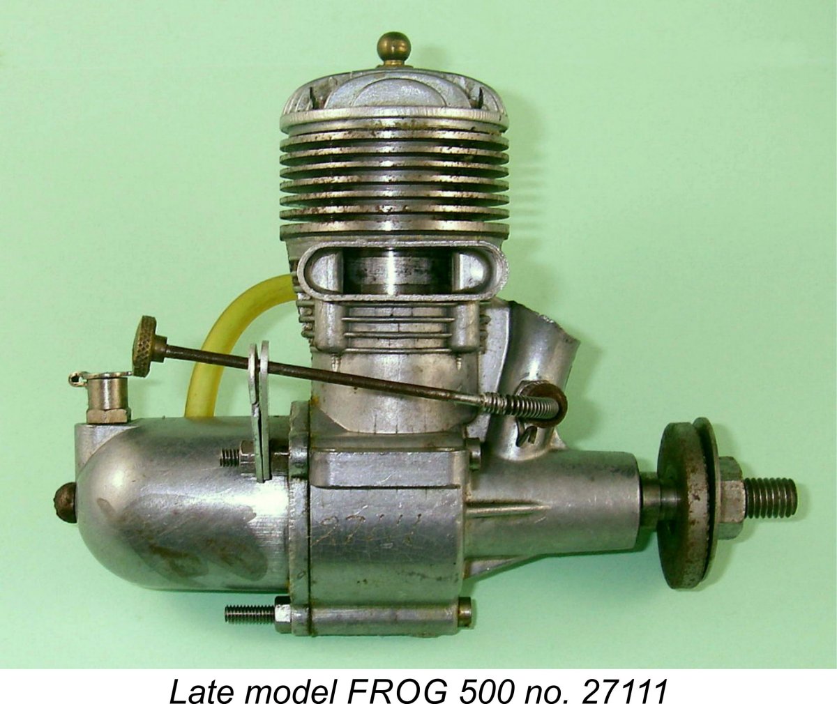

 However, this combination proved to be somewhat less than successful. The major problem was the fact that the Hurrikan featured automatic induction through a reed valve — something of a fashion at the time, since the
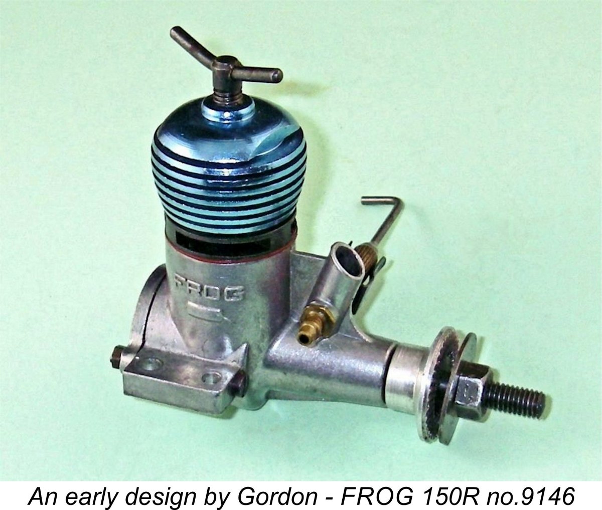
 As if the use of the centrifugal drum valve wasn’t enough, George also decided to re-introduce the concept of cross-flow loop scavenging with this design. This arrangement had first appeared in Britain on the very rare
 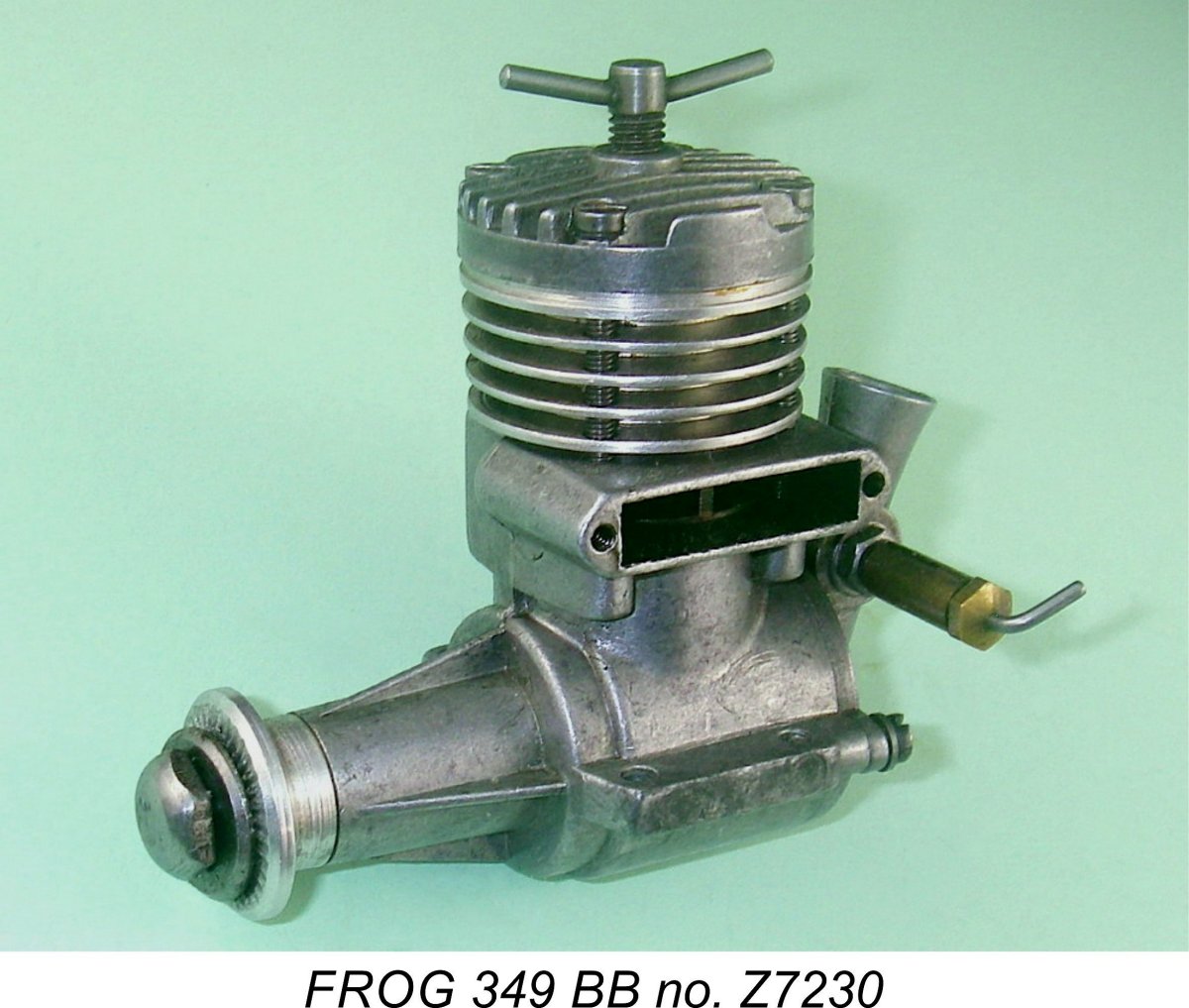 new FROG 349 (as it eventually came to be known) to the rather parasitic FROG nylon 9x6 propeller. This immediately placed a significant restriction upon the potential power output since it constrained the 349’s peak operating speed. The resulting engine therefore suffered from a relatively poor power-to-weight ratio. The prototype 349 tested by Gordon Cornell only turned the FROG nylon 9x6 prop at 11,000 RPM, while the lighter 249 Modified gave 10,600 RPM and the Oliver around 10,000 RPM.
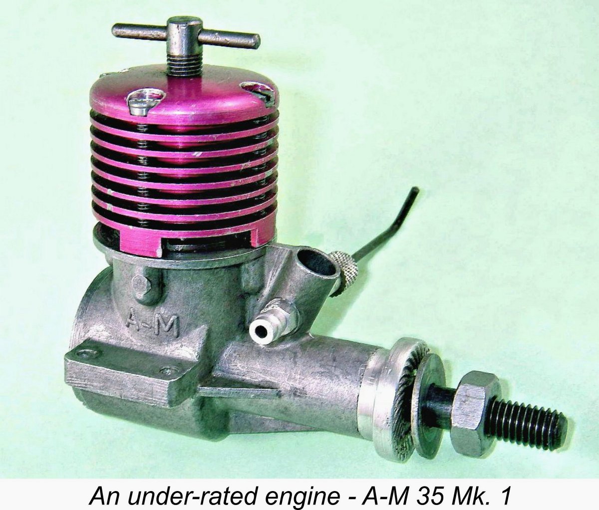
 However, this was not enough for Gordon. Although a very respectable performance indeed for a lightweight consumer-priced plain bearing diesel, it still fell somewhat short of matching several of the more costly high-performance 1.5 cc competition diesels of the day such as the individually-produced Oliver Tiger Mk. I and the
 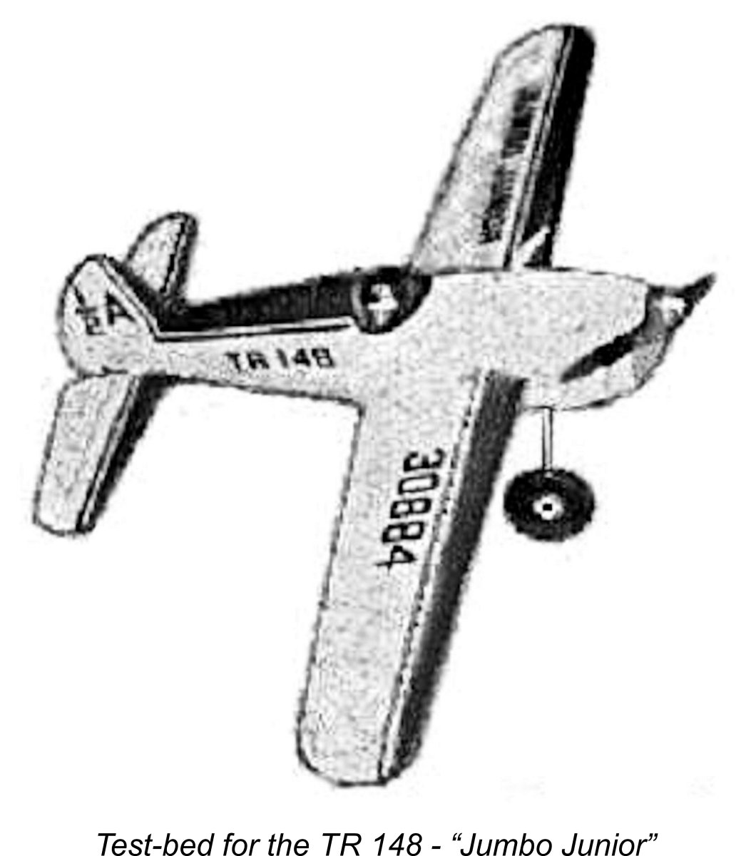 Having completed this prototype and found it to be a satisfactory performer on the bench, Gordon’s next step was to test it in competition. To this end, Gordon formed a team-race partnership with Peter Frazer, who became Gordon’s pilot. Gordon proceeded to build his second ½A team racer specifically for his TR 148 engine. This model was named “Jumbo Junior”. It proudly displayed the name of its unique powerplant on the side of the fuselage.
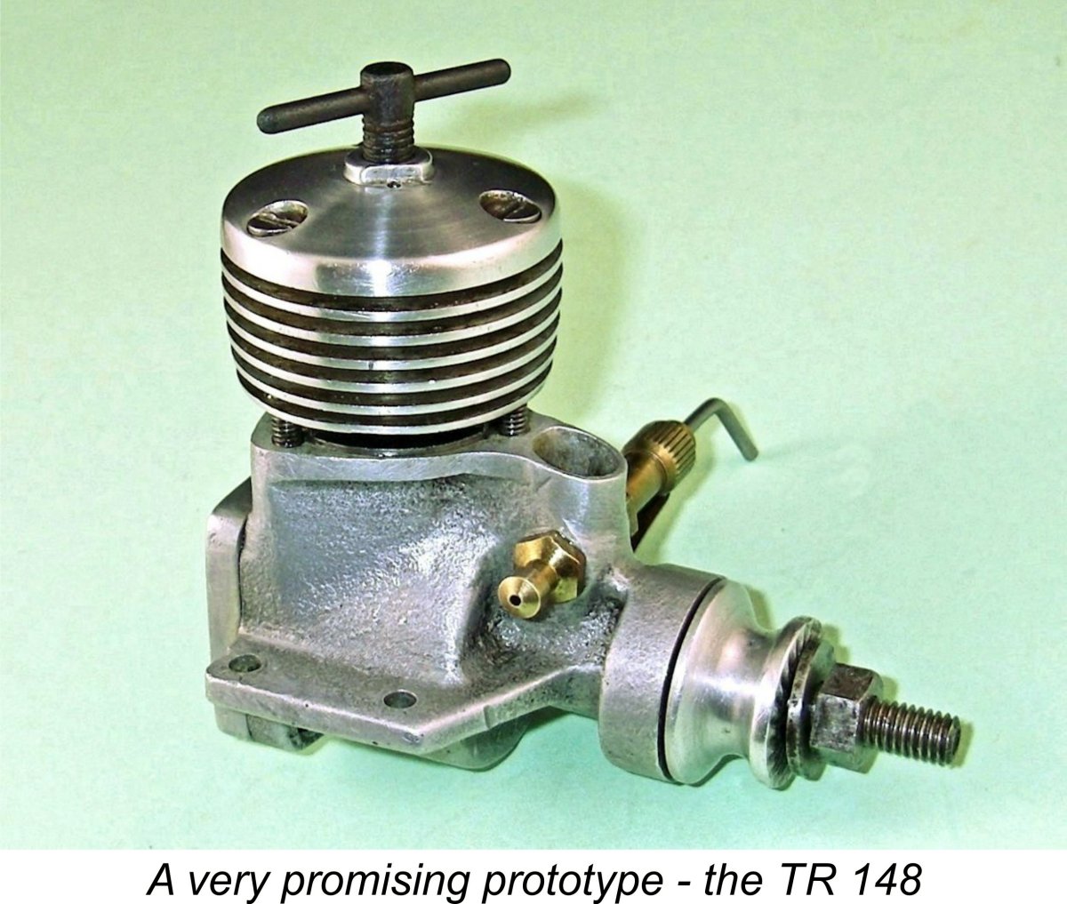 At the time in question, E.D. did not have a competitive model in the 1.5 cc category. Their old Hornet was woefully outdated, while their twin ball-race Fury of May 1958 was notably lacking in power by comparison with the opposition (including the FROG 150R) as well as featuring the reed valve induction which Gordon had already determined as being unsuitable for team racing.
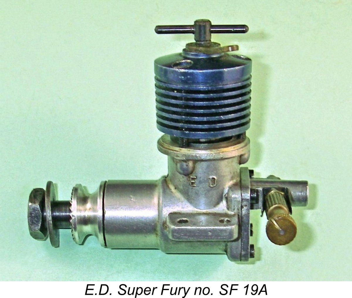 The result of all this testing and development work was the early 1960 appearance of Gordon's deservedly famous disc rear rotary valve (RRV) Super Fury. Interestingly enough, the original reed-valve Fury continued to be offered for some months thereafter, making its final appearance in E.D.’s advertising in June 1960, some months after the release of the Super Fury. This was undoubtedly a case of clearing unsold inventory to recover tied-up capital.
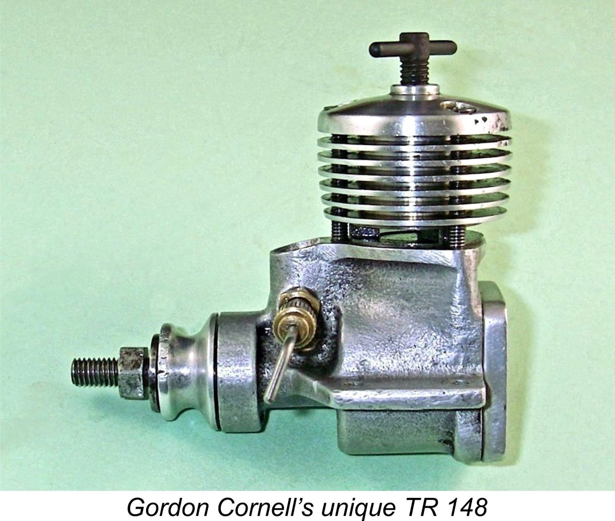 In terms of its general layout, the TR 148 was basically a fairly conventional competition diesel of its era. It was a twin ball-race unit which featured FRV induction allied to reverse flow scavenging, with unusually well-developed radial cylinder porting. In those respects, it broadly adhered to the established Oliver Tiger Cub pattern.
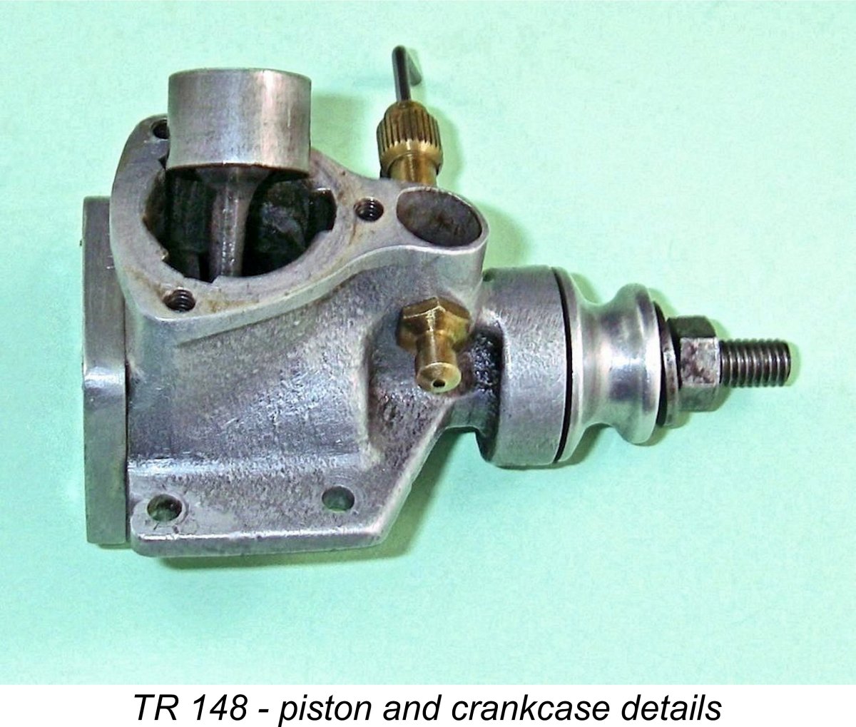 The engine is built up around a nicely-produced sand-cast crankcase which lacks any form of model identification. The upper crankcase has three bypass passages of generous dimensions cast into it internally. These register with three upwardly-angled transfer ports formed in the drop-in steel cylinder in the areas between the three sawn exhaust apertures. The transfer ports are of rectangular section, implying that they were first drilled and then squared off by hand-filing.
 cylinder retention screws. Despite the presence of these channels, the cylinder retains about 20 degrees of radial movement when loose, making it essential to check the alignment visually prior to tightening. As received, the engine’s cylinder was about 10 degrees out of its correct radial alignment, which would have resulted in the transfer ports being out of alignment with their respective bypass passages. Needless to say, I corrected this problem immediately, also taking a few photos of the piston and porting while doing so.
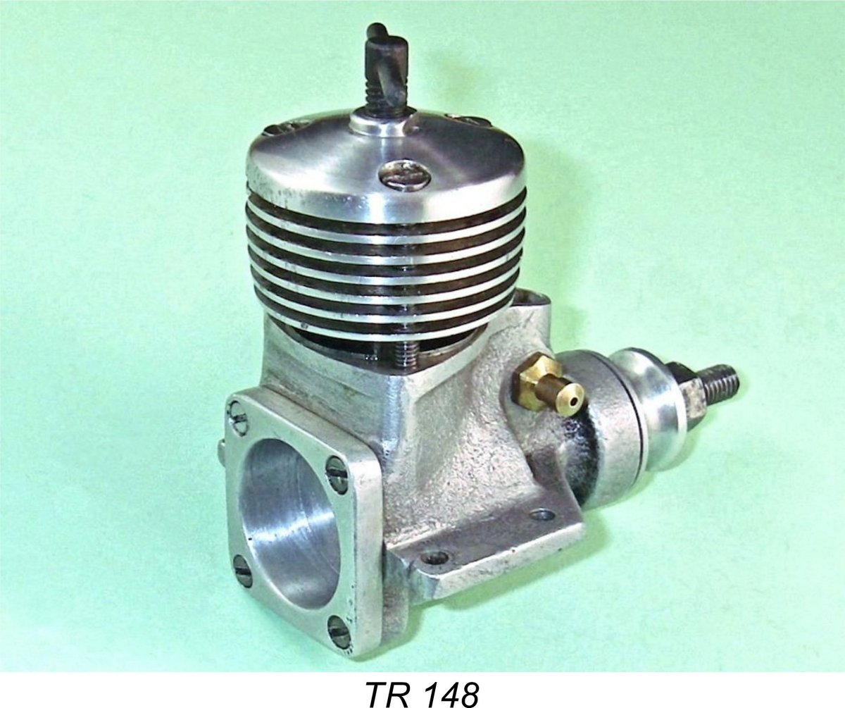 Further confirmation of the above assessment comes from the fact that the crankshaft induction port is a round hole rather than the more efficient oval or rectangular shape. The round hole configuration was clearly judged to be sufficient for the purpose of inducting sufficient fuel, while such a shape has far less potential impact upon crankshaft strength and durability. Gordon actually told me that he had some doubts regarding the adequacy of the crankshaft diameter in this prototype, so the use of a round hole as an induction port was certainly a logical move in terms of reliability.
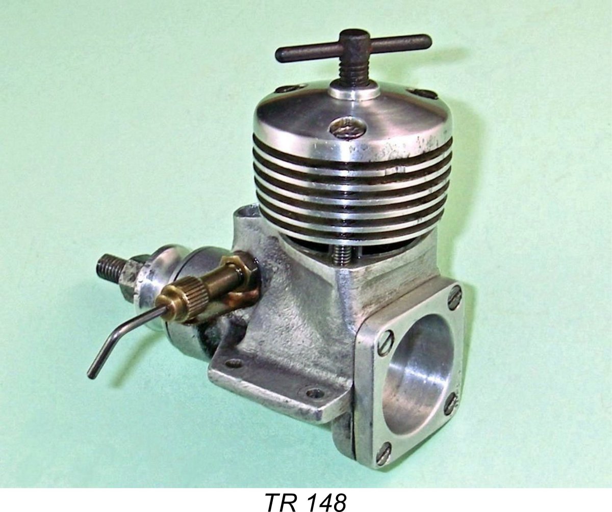 The rest of the engine was more or less conventional in terms of its construction. The backplate was secured by four neatly countersunk screws as opposed to the two nuts and bolts used in the FROG 150R. This was a very good move, because the wedging action of counter-sunk screws makes them far less prone to becoming loosened by vibration than conventional screws. Their only downside is the fact that the same wedging action gives rise to considerable bursting stresses upon the eyelets at the backplate corners which accomodate the screws. Care must be exercised not to over-tighten such screws, otherwise cracking of the eyelets could occur.
 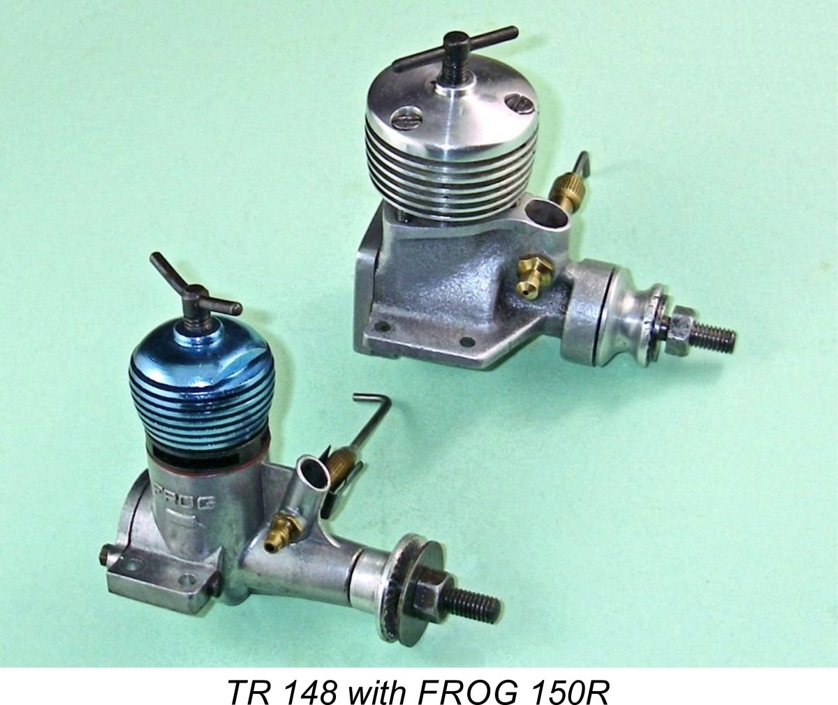 As my regular readers will know, I’m a big fan of context. For that reason, I generally avoid evaluating any engine in isolation. It’s my preference to test another competing design as well in order to provide a bench-mark for evaluation. Failing that, I will at least review the engine’s measured performance against published figures for other contemporary models in the same category.
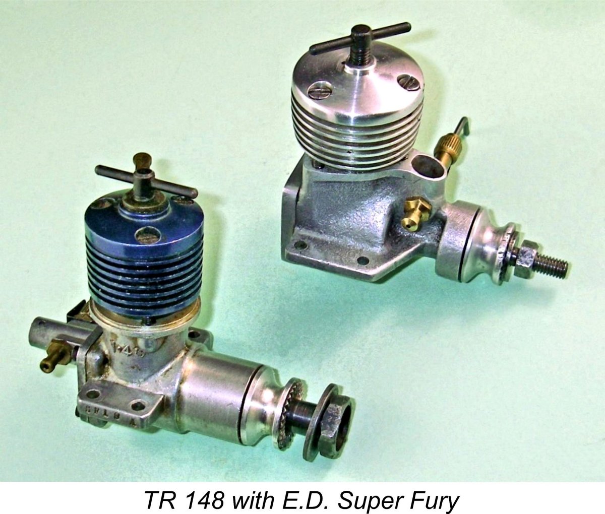 We saw earlier that the TR 148 was briefly considered by E.D. as a possible replacement for the Fury. However, various considerations led to the Super Fury being developed instead. How well did the Super Fury stack up against the potential alternative? Again, published figures would help to answer this question.
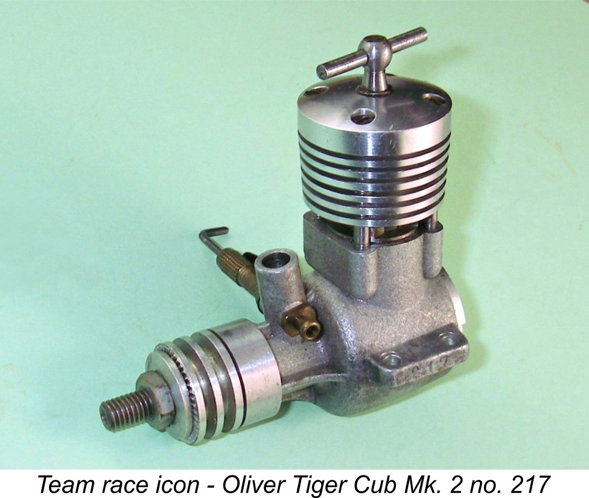 However, this delay had one very beneficial outcome – the opening of a suitable window of opportunity coincided with a visit from one of my regular readers, my valued friend and colleague Miles Patience from Horsham in England.
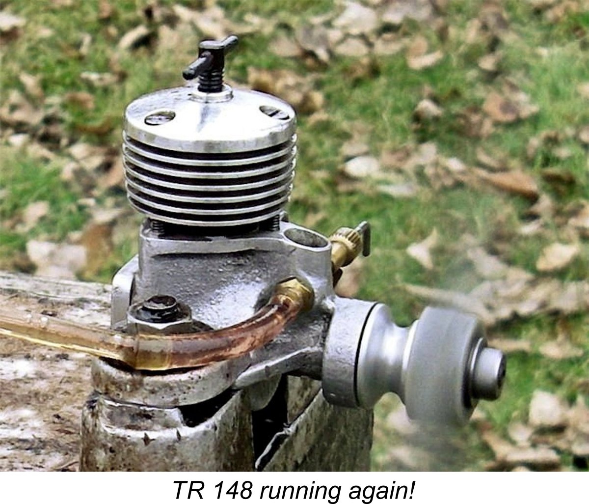
 mark. By that time the output of the E.D Super Fury had been improved to an impressive 0.232 BHP @ 17,500 RPM as measured by Peter Chinn in his re-test of that year. The later E.D. Super Fury Mk. 2 manufactured by E.D.’s Surbiton-based successor company was found to develop around 0.210 BHP @ 17,500 RPM, as recorded by Peter Chinn in 1970.
 148. Quite an accomplishment by Gordon Cornell!
| |