
|
|
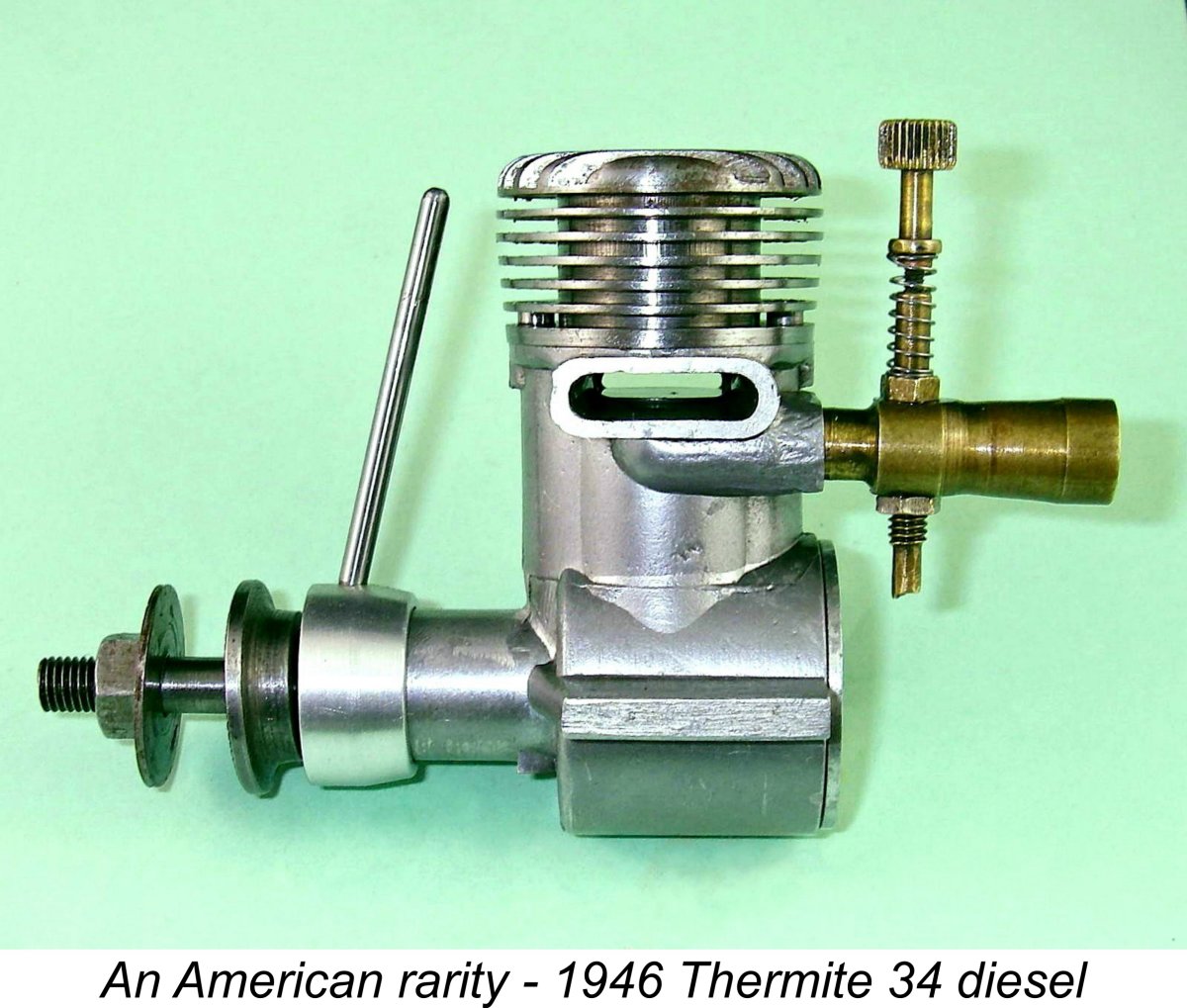
A Forgotten American Pioneer - the Thermite 34 Diesel
The Thermite diesel goes back to the earliest years of commercial model diesel manufacture. According to the ever-authoritative “Engine Collector's Journal“ (ECJ), the engine appeared in the latter part of 1945, almost a year before the introduction of any commercial British diesels from the likes of B.M.P., Caledonia, Owat, Leesil, Mills Bros., E.D., Kemp, Majesco, Clan, Aerol and FROG. This date is supported by the fact that the Thermite range with which this diesel is irrefutably associated disappeared around the end of 1945, for reasons which will become apparent as we proceed. The extreme rarity of the Thermite diesel, amounting to near-invisibility, may well imply that its creation was more of a small-scale experimental initiative than a full-scale production effort. It seems highly unlikely that it ever advanced beyond the prototype stage. This does not alter the fact that it was one of the earliest commercially-developed post-war model diesels regardless of country of origin. It was undoubtedly the first American design of this type. Moreover, as we shall see, the engine turns out to have incorporated a quite unexpected degree of original design thinking. Indeed, this model provides ample evidence to justify placing its creator Jim Brown at the forefront of pioneering model diesel designers worldwide.
Following Ted's unfortunate decline in health to the point where he became confined to a nursing home, I was privileged to acquire this very engine during the family-organized sale of Ted's amazing collection through SAM 8. This placed me in a position to subject it to a detailed analysis and bench test. My efforts led to the November 2012 publication of the original version of this article on the late Ron Chernich’s “Model Engine News” (MEN) website. So why the article’s re-publication here? Firstly, because my mate Ron left us in early 2014 without sharing the access codes for his heavily-encrypted site. Accordingly, no maintenance has since been possible, the result being that the MEN site is slowly but perceptibly deteriorating as the various links fail progressively - an inevitable process which can have only one ending in the long run. I was unwilling to risk the loss of reader access to the information so painstakingly gathered on the Thermite diesel, hence the article’s re-publication here. Perhaps even more importantly, I’ve since gained a broader understanding of the background to the appearance of this very rare engine. I’ve also caught a few errors in my original text, several of them serious. Finally, a number of key links associated with the Thermite story were omitted from the original article, while many of those that were included have since been updated or replaced. All of these issues required addressing through the publication of a revised version of the article. Having justified the appearance of this revised text and having set the stage, let's review the background to the development of this highly intriguing model engine. Background
The fact that the model diesel did not require a heavy and potentially undependable airborne ignition support system gave it an obvious advantage over its spark ignition counterparts. Naturally, this advantage was just as apparent to American modellers as it was to their European colleagues. The initial exposure of US modellers to the model diesel came about in mid 1945 as a result of the early post-war importation of wartime European examples, predominantly French and Italian, by servicemen returning from trans-Atlantic duty in WW2. Model diesel development had been ongoing in those countries (among others) since 1941 despite the disruption caused by the war. By 1943/44, there were numerous examples available to US servicemen.
Impressed by the performances put up by the best of these imported European diesels, a number of US manufacturers decided to enter the model diesel market with home-grown designs of their own. It may come as something of a surprise to some readers to learn that the number of North American manufacturers involved with model diesel development at this pioneering stage prior to 1947 almost certainly exceeded the British total during the same period.
In 1941 Jim relocated to Oakland, California, concurrently switching his brand name from Little Dynamite to the equally explosive Thermite. The Thermite series was launched with The attention of the American public and manufacturing sectors was naturally deflected away from models and modelling during America's war years from December 1941 to mid 1945. In addition, the availability of materials and manufacturing capacity for such items as model engines was very much constrained as resources were diverted into war production. Despite these constraints, the production and further development of the Thermite range somehow continued at some level throughout this period. It’s possible that Jim Brown managed to obtain an ”Education Priority” materials supply rating, enabling him to maintain limited production on the basis of his engines’ educational value in promoting interest in aeronautics among young potential air force recruits.
The Thermite engines seem to have been mainly built to custom order at this stage, although a few were reportedly seen in Bay area hobby shops from time to time. As a consequence of this situation, the engines acquired some brand recognition in the Oakland area but were practically unknown elsewhere. As WW2 drew closer to its increasingly-predictable end, limited commercial production of model engines in the USA resumed in September 1944 when the US War Production Board decided to release sufficient material and manufacturing capacity for non-military purposes to allow this to happen. At this point, Earl Vivell entered the picture, making arrangements for Jim Brown to become involved with the manufacture of his expanding Vivell model engine range. Earl Vivell was an "engine guy" with a difference! He was not a manufacturer himself, actually being a successful hobby shop owner and entrepeneur with a strong personal enthusiasm for models. His Vivell range of engines was designed and manufactured for him by others - his own role was confined to the marketing and promotion of the engines. Earl Vivell's involvement with model engines stemmed originally from the fact that as the end of WW2 drew ever closer, he became aware that the Comet Company of Chicago was planning to abandon their Comet 35 model which had been produced for them by a chap named Jack Keener. He made contact with Keener and persuaded him to continue the manufacture of the Comet 35, albeit under the Vivell name with a few design changes.
Earl Vivell sought Jim Brown's involvement with the manufacture of the Vivell engines on the basis that he wished to expand his range by marketing Jim's Thermite 49 model under the Vivell trade-name. This led to the 1946 appearance of the Vivell "Forty-Niner", which Jim Brown manufactured for Earl Vivell. The extent of Jim's work for Vivell soon reached the point where he was left with no time to carry on with his own Thermite range. Consequently, as of 1946 that range had been consigned to history. But not before Jim had engaged in what proved to be the first of several forays into the world of model diesels! It's clear that he must have somehow become aware of the model "diesel" (actually compression-ignition) principle very early on, perhaps through wartime correspondence with a serviceman friend in Europe, since within a matter of months following the mid-1945 cessation of hostilities he had produced a very few examples of our subject model, the Thermite diesel. The fact that this engine was developed under the Thermite name at a time when Jim was becoming increasingly focused on developing the Vivell range presumably indicates that at this stage Earl Vivell wasn't interested in diesels. However, Jim Brown certainly was! Consequently, he somehow managed to set time aside from his commitments to Vivell to make a few examples of this very interesting model diesel engine. In doing so, he became the first US commercial manufacturer to develop a model diesel - more than that, he was among the very first post-war constructors of model diesels world-wide, being preceded only by such pioneering European marques as Micron and Jidé in France along with Etha and Dyno in Switzerland which had become established during the war years. This makes the Thermite diesel an unusually interesting and significant model for study. Apart from being the first model diesel to be developed by an American commercial manufacturer, it proved to be the final Thermite design of them all since the pressures of Vivell production claimed Jim Brown completely after 1945. As far as is presently known, it was also the only side-port model ever produced by Jim Brown. To cap it all, the engine probably never made it past the prototype stage, making it one of the rarest commercially-developed model diesels of them all. Let's take full advantage of the present opportunity to have a close look at this very interesting and historically significant engine. The Thermite Diesel Described
The rarity of this engine is such that I was unable to find so much as a single image of a complete original unit from which to copy the missing parts. Accordingly, the prop driver and needle which appear in the attached images are functional replacements of my own design and manufacture. The needle is a stand-off copy of the type of component often used on the Thermite spark ignition engines, so it's probably not too far off. I have no way of evaluating the accuracy of the repro prop driver - all I can say is that it works well and looks right! I can always make new parts if authoritative information regarding the originals ever becomes available. When describing an unfamiliar engine, it generally seems best to start off with a few vital statistics. Here we encounter our first major surprise! The Thermite is a side-port compression-ignition engine having bore and stroke measurements of 0.770 in. (19.56 mm) and 0.730 in. (18.54 mm) respectively. Fair enough - but these carefully checked (and repeatedly re-checked) measurements yield a calculated displacement of 0.340 cuin. (5.57 cc)! Try as I may, both the micrometers The production of an overbored variant of a Class B engine to permit entry into a higher class using the same model was by no means uncommon among American manufacturers. This being the case, it's entirely possible that a .299 cuin. Class B variant of the engine did exist or was at least envisaged - reducing the bore by 50 thou to 0.720 in. would do it. However, this ain't it! At this point I wish to make it absolutely clear that this in no way represents any error on the part of my good friend and valued colleague Tim Dannels! Tim didn't own this engine, thus being entirely dependent on information supplied by Ted Enticknap for the engine's entry in AMEE as well as an external examination during a visit. Although I very much doubt that Ted ever measured the engine, I know that he truly believed it to be a 29, probably on the basis of first-hand knowledge that such an engine was in fact produced by Jim Brown. Ted was unusually well-connected with early post-WW2 model engine producers in the West Coast region of the USA, often serving as a field tester for their developing products. I always considered him to be a reliable source, as did Tim.
The Thermite diesel is built around a main casting which incorporates the main bearing housing, crankcase, beam mounting lugs, bypass passages, induction boss and twin exhaust stacks in a single component. The fact that this casting was very cleanly produced using a permanent mould certainly requires some form of credible explanation given the extremely small production figures apparently achieved. Although certain Japanese manufacturers are known to have employed die-casting even for very limited-production models, this was very far from usual among American producers. The use When considering this point, several architectural features appear highly relevant. Firstly, there's the appearance beneath the main bearing of a vestigial portion of an updraft carburettor boss similar to those featured on Jim Brown's earlier Little Dynamite FRV models. Secondly, the exhaust stacks bear a very close similarity to those of the Thermite FRV models, as do the beam mounting lugs and fore-and-aft cylinder hold-down lugs. Taken together, these features certainly imply a direct relationship to an earlier Jim Brown model. However, if the diesel cases were cast from a modified die originally intended for an earlier FRV design, the required modifications would have been quite extensive given the previously-noted fact that Jim Brown is not known to have marketed a side-port spark ignition model under either the Little Dynamite or Thermite brand names at any time.
For this reason, I actually believe it to be far more likely that Jim already had a limited number of previously-produced castings which had been intended for a far earlier Little Dynamite side-port project which had been abandoned at some indeterminate point prior to Jim moving to Oakland and switching his brand name to Thermite. When Jim subsequently elected to give compression ignition a try, most likely out of plain curiosity to see how this European innovation worked in practise, what could be more natural than for him to draw upon a batch of cases already on hand as the basis for his initial attempt at diesel design? To me, this makes far more sense than the idea of Jim going to the trouble of creating a new or modified die and having a batch of new castings made. Of course, if the above scenario is correct, then Jim would have had to create the required die during the pre-war Little Dynamite period to produce the castings in the first place. Unless the die had been lost in the interim, he would thus have been equipped to manufacture a new batch for his 1945 diesel project. However, I personally still find the "existing casting" scenario with its reduced level of effort and financial investment to be considerably more likely given the surrounding circumstances. That said, I freely admit that this opinion is no more than speculative in the absence of any direct supporting evidence. That situation is unlikely to change in the future.
As stated earlier, Ted Enticknap was unusually well connected with the manufacturing community in his day, serving as an independent field tester for some of them. In consequence, he owned a number of engines in the prototype category. This may well be one of them. It may even be an overbored .34 cuin. prototype based on an earlier .299 cuin. model having a smaller bore of, say, 0.720 in. This could explain Ted's citing of its displacement as .299 cuin. This view of the matter is reinforced by Tim Dannels' recollection that when Ted provided the information about the Thermite diesel as it appeared in AMEE, he actually mentioned something about this example being some kind of experimental or prototype model. This certainly fits with the above observations. Indeed, the terms "experimental" and "prototype" may legitimately have been applicable to the Thermite diesel project as a whole, even in Jim Brown’s mind. My sincere thanks to Tim for so generously sharing his recollections with me. The appearance of the Thermite diesel is somewhat deceptive in certain respects. At first sight, the absence of either a plug or any form of compression adjustment on the cylinder head gives the engine the general appearance of being another of the fixed-compression units that were not uncommon at the time when it was designed. However, things are not always as they first appear! The give-away is that strange and rather awkward-looking arm attached to the front of the main bearing where the timer arm on a spark-ignition engine should be.
Since the actual bearing itself is reamed eccentrically in the bushing, the effect of turning the bushing in the main bearing casting is to raise or lower the crankshaft relative to the rest of the engine, in particular the cylinder head. This in turn naturally raises or lowers the compression ratio by altering the elevation of the piston crown relative to the cylinder head at top dead centre. In effect, the working piston does double duty as both the power and contra pistons, using the con-rod as the compression screw!
The arm which was fitted to the engine as received was unquestionably non-original. It was quite crudely drilled, hacksawed and filed from a piece of scrap aluminium alloy plate, in stark contrast to the truly excellent workmanship displayed throughout the rest of the engine. It was also poorly designed, being both bulky and ill- Naturally, I have no idea what the original might have looked like. I made a functional unit which looked far more in keeping with the rest of the engine and also worked in the correct manner. My system employs a turned clamp which grips the protruding portion of the main bearing bushing using a 4-40 machine screw for tension. The rear of the clamp is recessed to slip loosely over the un-machined main bearing housing. A thick fibre washer is located at the internal step formed The degree of friction is easily adjustable. The first step is the removal of the prop and driver. A simple tubular sleeve is then fitted which bears against the front face of the clamp - a 15mm socket works well. After this sleeve has been lightly tightened against the clamp face (using the standard prop nut and washer), the clamp is slackened off from the bearing extension. The sleeve is then progressively tightened against the The beauty of the eccentric bearing system for a diesel engine aimed at a marketplace which was accustomed to spark ignition operation is of course that the compression arm functions exactly like the timer arm on a spark ignition unit by controlling the ignition timing. Operation of such an engine would be instantly and comfortably familiar to anyone having experience with spark ignition. An important additional advantage of the use of the clamping system to attach the arm to the bushing is that it allows the arm to be positioned in the most practicable alignment once a running setting has been established. Finally, the system limits the upper compression ratio which can be applied, reducing the potential for over-compression and hydraulic lock in the hands of an inexperienced diesel user.
Another factor which will inevitably be affected by the application of eccentric-bearing compression adjustment is the lateral alignment of the crankshaft centre line relative to the cylinder axis. Engines featuring some degree of lateral crankshaft offset from the cylinder axis are known as desaxe designs. Contrary to a seemingly widespread belief, the name is not derived from that of its inventor but rather from the French word "désaxé", which means "off-centre" or “unbalanced”. The advantages of a desaxe layout arise from the fact that by moving the shaft centre-line towards the compression-stroke side of the engine (the left side looking forward for a model engine designed for normal rotation), the rod swing angle on the power stroke can be appreciably decreased. This results in an For all of these reasons, the arrangement is widely employed today in full-sized engine practise - the petrol engine in the ground-breaking Toyota Prius hybrid is a notable example. In addition, the desaxe principle has been quite commonly used in certain model engine ranges, the Fox marque being perhaps the best-known example. Returning to the Thermite diesel, it should be immediately apparent that the rotation of its eccentrically-reamed main bearing will change not only the crankshaft elevation relative to the cylinder head but also the degree to which the crankshaft is laterally displaced from the cylinder axis. Hence changes in compression ratio have the potential to affect the degree to which the engine incorporates the desaxe arrangement while in operation. To take best advantage of the desaxe effect, the bushing on an eccentric-bearing compression ignition engine having a centrally-bored main bearing housing should ideally be installed with the actual bearing bore offset towards the compression stroke side, that is, towards the rear-view left-hand side of an engine intended for normal rotation. Another advantage of this configuration would be that the tendency of the bushing to rotate with the shaft due to friction would be resisted by the counter-rotational couple created by conrod pressure acting upon the shaft offset.
An obvious fix here would be to bore the main bearing casting offset to the left so that the eccentrically-bored main bearing itself would be located on or near the cylinder axis at its point of maximum lateral displacement to the right. Any movement in either direction would then have the effect of increasing the desaxe displacement in the desired orientation. However, this was not factored into the design of the Thermite diesel. In the end, it all depends upon one's priorities - it wouldn't take long to get used to either arrangement. Given the advantages cited above, I elected to set this example up for normal desaxe operation, with the eccentric bearing journal positioned to the left of the engine's axis (viewed from the rear). This of course means that the timing arm operates in the reverse sense from a spark ignition timing arm, but that's fine by me! The orientation of the bushing could of course be easily re-set if desired to achieve the opposite mode of operation.
Now it gets interesting! All of these engines date from 1946 or later apart from the French Airplan 2.15 cc model upon which the Airstar 2.15 cc offering of 1948 was directly based. The Airplan model was designed by Roger Fargeas, appearing in late 1945 at around the same time as the Thermite diesel. As far as I can tell, this was the first commercially-released European diesel to feature the eccentric-bearing approach to compression adjustment. The Fargeas-designed Ouragan models made their appearance in 1946. The Clan design appears to have originated in early 1947, while advertisements prove that the M.S. 2.5 cc undoubtedly reached the market in December 1947. Although Jan David-Andersen had begun experimenting with model diesels in 1944 Norway while WW2 was still ongoing, he Suddenly, the Thermite diesel takes on a quite unexpected significance! It clearly pre-dates all of the above post-WW2 models, which were therefore not available to serve as design influences. The Airplan 2.15 cc model evidently appeared in late 1945, but by that time Jim Brown had already developed the Thermite design which forms our main subject. Although it seems highly unlikely that Jim Brown managed to get his hands on a prototype example of the Airplan, it has to be admitted as a possibility. It’s perhaps somewhat more likely that some American serviceman friend of Jim’s saw an Airplan prototype while in Europe and made Jim aware of its design principles. Sadly, the validity of either possibility can no longer be tested given the passage of time. Whatever the circumstances surrounding its inception, the Thermite appears in fact to have been one of the first, if not the first, commercially-developed model diesel engines to use eccentric-bearing compression adjustment! It also evidently carries the distinction of being the largest-displacement diesel ever to feature this arrangement. Moreover, the seeming improbability of Jim Brown having somehow gained direct access to an Airplan prototype makes it difficult to avoid the conclusion that this concept may well have been a Jim Brown original rather than a re-hashing of an idea acquired from some European prototype. A classic case of parallel development if so, since it's very doubtful that any European diesel manufacturer ever so much as heard the name Thermite!
The cylinder sleeve, cooling fins and cylinder head are very nicely machined in one piece from a single steel billet. A lot of work went into this component! The bore is of course blind. The cylinder sleeve below the cooling jacket forms a spigot which is a smooth push fit in the inner bore of the upper crankcase. The stiffness of the assembly permits the use of only two screws to attach the cylinder to the crankcase, just as in the later FROG "bicycle-spoke" engines. More very logical thinking is apparent at this point also. At first sight, one would expect to find two long screws holding the cylinder in place from the top. However, this is not the case in reality. The installation holes are drilled vertically down through the cooling fins at head clearance diameter (5/32 in.) for the 4-40 slot-head hold-down screws. This diameter is carried all the way down to the thicker flange below the cooling fins which serves to locate the cylinder vertically in the case. However, the holes through this lowest flange are only drilled to clear the 4-40 threads of the two installation screws. The screw heads thus bear directly upon the cylinder location flange, accordingly having extremely short stems. The effect of this arrangement is to eliminate any hold-down stresses from the working length of the cylinder bore - a very desirable provision. Jim Brown's earlier Little Dynamite and Thermite sparkies featured a similar arrangement. An offsetting design weakness becomes apparent at this point. For one thing, the use of only two 4-40 screws to retain the cylinder appears rather on the minimal side for a diesel engine of this displacement. This is compounded by the fact that the thread length provided in the case for the two installation screws is pretty marginal, especially since the threads are cut directly into the relatively soft aluminium alloy of the case. The presence of the two bypass passages eliminates any opportunity to deepen the relevant holes, since they already penetrate into the passages at the top. Accordingly, great care is required when re-assembling this engine to avoid over-tightening and possible stripping of these threads. Tight enough and no more is definitely the correct approach here, along with regular periodic re-checks of tightness.
Following removal of the two hold-down screws, the cylinder slides easily out of the location bore in the crankcase, in which it is a very close but smooth push fit. This fit is extremely important in this design because the cylinder location flange is above all of the ports. Hence the crankcase seal is entirely dependent upon the close fit of the cylinder in the case. Despite this, a gasket is used between the cylinder and the upper surface of the case, even though such a provision seems a bit redundant. Perhaps it represents the provision of a means of adjusting the compression ratio range provided by the eccentric bearing.
Con-rod clearances are quite tight, especially at higher compression settings with the crankshaft raised in the case. This necessitates the provision of a pair of chamfered scallops on the lower edge of the cylinder liner, one on each side. These may be clearly seen in the image of the detached cylinder included earlier in this article.
The 5/16 in. dia. main crankshaft journal is a very close but smooth fit in the eccentrically-bored bronze main bearing bushing. The journal diameter seems a bit marginal for a diesel engine of this displacement, but it must be recalled that the shaft is not weakened by the presence of induction passages and is also very well supported in its closely-fitted bearing. Given the relatively low operating speeds and power output which may be expected with this unit, the shaft would probably stand up OK in service with careful handling. The front of the crankshaft has a square-section segment immediately forward of the main journal to serve as a means of locking the prop driver to the shaft. The length of this square feature played a major part in determining the thickness of the replacement steel prop driver that I made for the engine. The prop is secured in the usual manner using a simple nut-and-washer combination on a 1/4-28 thread.
The needle itself was missing as received, but the spraybar shows that it was of the externally-threaded variety, like those of other Thermite models. It was also quite clear that a coil spring was used to tension the needle, once again along standard Thermite lines. I made a functional spring-tensioned replacement which bears a general similarity to those used in other Jim Brown designs. There's no way of knowing for sure if the engine ever had a hang-tank, but none of the other Thermite models had tanks. Accordingly, I didn't bother to make up a tank for this engine. Overall, the standard of workmanship is extremely high. In fact, we have to conclude that this is a very well thought-out design indeed, and one which was most competently constructed by any measure. Given these observations, one might logically expect this engine to perform quite strongly by 1945 model diesel standards. So how does it actually run? Only one way to find out! The Thermite 34 Diesel On Test Testing an engine of this vintage and rarity is always a bit fraught, particularly when dealing with a pioneering diesel dating from a time when the need to construct such units to withstand the far higher stresses imposed by diesel operation was not yet fully appreciated. However, I felt that if I didn't give it a go for the record, no-one else would! So, armed with a few suitable test props plus some standard diesel fuel which had proved extremely satisfactory in other engines, I set the Thermite up in the test stand and prepared to boldly go where few have gone before ............... In view of the seemingly rather marginal dimensions of the crankshaft journal and rod bearings, I resolved in advance that I would not push the old Thermite in any way and would back off at the first sign of undue stress on the engine. I also planned to keep running time to the bare minimum necessary to form a valid impression of the engine's performance characteristics - a lengthy running-in period was never on the cards. Hence what follows cannot be viewed as anything approaching a comprehensive or necessarily conclusive test.
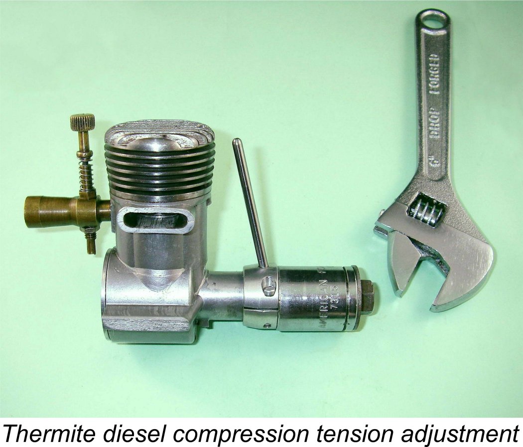
For this reason, it's always wise to start off testing such an engine using a heavy large-diameter airscrew having plenty of flywheel inertia. I elected to go with a 12x6 APC prop, a very hefty club which I had found to be highly effective for initial starts with the 5 cc K Vulture and Drone diesel. This turned out to be a very happy choice. I had previously adjusted the compression lever orientation so that the lowest-possible compression ratio was obtained with the control arm pointing straight up, as seen in the accompanying image. I began my starting efforts with the lever set in this position. This is always the safest approach, particularly with a rare and irreplaceable engine of uncertain mechanical integrity. The needle was set relatively lean, as determined by ear using the old squeeze-bottle blowing trick - better this than risk flooding the beast and inducing a potential hydraulic lock with its associated elevated stress levels. To ensure that there was fuel in the cylinder, I administered a very light "dry" prime (exhaust ports closed) before flexing the old flicking finger. Compression seal was outstanding, thus offering no excuse for any starting problems. As usual with larger diesels, the Thermite proved to require a fairly high compression ratio for starting. A healthy crank of the compression lever in the direction of rotation soon had it popping and banging, then making a few short bursts. However, I couldn't get it to keep running until I opened the needle some more. I did this in small increments, finally achieving a start at just under two turns.
Running qualities proved to be outstanding. Since the piston fit actually felt relatively tight, clearly having had little or no previous running time, I kept the needle a fraction rich and the compression just a hair lower than optimum. The exhaust oil colour quickly cleared up to a nice clear honey brown, indicating that all was well internally, and the engine settled down to a steady 5,800 rpm with minimal misfiring, which it would seemingly maintain indefinitely at the less-than-optimum settings which I used. Vibration levels were relatively high without being excessive, although I wouldn't want to push the engine much faster than I did. The compression lever proved to be both effective and convenient in use - I could easily get used to this system! It appears that the basic geometry of the engine was very well chosen, since the best running compression setting proved to be exactly mid-way in the available compression range, that is with the eccentric main bearing bore set at its maximum left-hand displacement viewed from the rear. The engine was thus operating in desaxe mode with a 0.025 in. crankshaft offset - probably close to the ideal. The friction arrangements incorporated into my replacement compression adjustment system proved to have been very necessary. After a few runs, the system was in need of re-adjustment since the level of friction slackened off to the point where the compression control began to creep in the direction of engine rotation, thus inducing a slow but potentially damaging upward drift in the compression setting. Re-adjustment was a simple matter using the approach set out earlier, after which no more difficulty was experienced during the balance of the test. Presumably the fibre washer took a "set" over the first few operating cycles, as one might expect. I would anticipate having to re-tension the system fairly regularly when the engine was in service in a model.
As expected, I encountered no trouble with the unthreaded venturi tube coming loose during operation. However, the two cylinder hold-down screws did need re-tightening after a few runs, probably as a result of the cylinder base gasket taking a “set” following my re-assembly of the engine. The fact that the very short thread length precludes tightening them down really hard means that periodic checks on their tightness are definitely necessary. However, no further tightening was required during the balance of the test. I put on 20 minutes in 4 minute runs, allowing complete cooling between runs following a few test hot restarts. In the latter regard, one thing that was very noticeable was the engine's tendency to run unusually hot. I would hazard a guess that the rather tight piston fit had a lot to do with this - even after the above amount of running, the fit remained very much on the sticky side. A lot more running would doubtless free things up, but I was not prepared to subject this ultra-rare and seemingly irreplaceable engine to the associated wear and tear. Even so, running remained very steady at all times. Hot re-starts were immediate at running settings with just a couple of choked flicks as preliminaries. Cold re-starts were found to be quite straightforward with several choked flicks and a modest increase in the compression setting. Following the initial start, priming proved to be unnecessary either hot or cold. The engine always started with just a few flicks after choking. Full marks for handling, in fact! One point that I did check was the Thermite's response to a lighter prop. Given the well-earned reputation of larger diesels for requiring a heavy prop with plenty of flywheel, I thought that it might be instructive to try an 11x6 wood prop just to see what would happen. This far lighter prop was found to lack the flywheel effect necessary to carry the engine over from the initial firing stroke, resulting in a series of pops and bangs but no start, try as I would. A switch back to the heavier APC glass fibre airscrew quickly restored happiness, with an immediate start being readily obtained. Again, some more running time to free up the piston a little would doubtless improve this situation. Feeling by this time that I'd subjected the poor old Thermite to as much abuse as it deserved after surviving for all these years, I contented myself with checking the available speeds on a small range of seemingly suitable props, keeping the fully opened-out check runs to very short duration in recognition of the residual tightness in the piston/cylinder fit. The still-tight engine got the test 12x6 APC up to a steady 6,000 rpm, which equates to around 0.178 BHP - hardy an eye-opening performance for a 5.6 cc engine, although a lot of air was being shifted. A switch to an 11x6 APC didn't produce as much of an improvement as I was expecting - the engine could only manage 6,300 rpm on this prop, implying an output of around 0.142 BHP. The peak had clearly been passed by the time this speed was reached, with the power curve declining sharply in the characteristic manner for side-port designs.
Now before we dismiss the poor old Thermite on the basis of these figures, it's important to recall two factors. One, we're speaking about a side-port diesel dating from 1945, when diesel design was still in its infancy, particularly in America. And two, the piston fit in this example is still what I would objectively classify as unduly sticky. With a fair bit more running, I have little doubt that all of these figures would improve quite considerably.
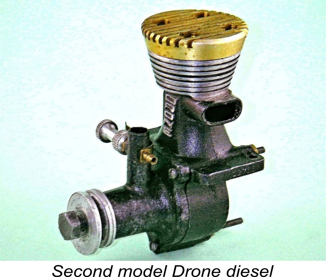
The engine came through its 30 minutes of fame with colours flying high, seemingly ready to do more work if desired. If fully run-in, there's little doubt that performance would improve quite measurably. However, I'll leave that to some future owner - for me, the fun of restoring this rarity to running condition and actually experiencing it in operation has provided more than sufficient satisfaction to justify my acquisition! I would summarize the Thermite 34 as a well-made, easy-starting and smooth-running engine which is extremely straightforward to manage once running and swings a substantial airscrew at quite sufficient speeds for most sport-flying requirements by the standards of its day. It is also unusually compact for its displacement. Any contemporary modeller who saw one of these in the hands of a competent operator would surely have been quite impressed! Too bad that Jim Brown was forced to abandon his promising diesel project so early. However, there was more to come ... read on! Aftermath - the Vivell Precision Diesels It appears highly probable that Jim Brown’s pursuit of his Thermite diesel project did not extend much if at all past the end of 1945, being confined to the production of a small handful of test prototypes, one of which ended up in the hands of Ted Enticknap, as did a number of test prototypes of this era from various manufacturers. According to Tim Dannels, Jim was very fond of experimenting - a number of his designs were made in extremely small batches during the Thermite years, this clearly being one of them. The very brief existence of the Thermite diesel almost certainly had nothing to do with any fundamental shortcomings with the engine itself. Rather, it was likely down to the simple fact that as 1946 rolled around the pressure on Jim Brown to expand production of the Vivell engines left him no spare time to continue with the Thermite range. Consequently, the Thermite diesel enjoyed only a very brief period of attention from its designer. The extreme scarcity of surviving examples (the illustrated engine is presently the sole surviving example worldwide of which I am personally aware) However, this didn't stop other American manufacturers from pursuing the model diesel concept. First among these were Barney Snyder and William (Bill) A. Ruff, who designed and manufactured the excellent C.I.E. 10 diesel under the auspices of the Compression Ignition Engines Division of Modelcraft Hobbies in Los Angeles. This very capably-designed, well-executed and fine-running engine appeared on the market in late 1946. Considerations of time and place make it appear not unlikely that exposure to the Thermite diesel may have played a part in engaging the interest of Snyder and Ruff in the development of model diesels, although the Thermite doesn't appear to have influenced them at all in design terms. The C.I.E. was quickly followed by other American diesel designs, the most successful of which was the 5 cc Drone fixed-compression model of 1947 which was sold in two distinct variants. Other contemporary The EDCO company of Del Mar, California, also developed a diesel model, although this never progressed past the prototype stage. The same applies to America's Hobby Centre (AHC) of New York, whose own diesel development program was also halted at the prototype stage, as detailed elsewhere. A few .604 cuin. Ken diesels were also produced by the Kencraft company of Garden Grove, California, while Super Motors Inc. of Cleveland, Ohio, constructed a small handful of Delong 29 diesels. Up in Canada, both Al Salonen of Queen Bee fame and Strato manufacturer Randall Bainbridge produced a very few prototype diesels. As I stated at the outset, the number of North American firms having some level of involvement with model diesels at this time was at least comparable to the number of such firms active in Britain, a fact which may surprise many of my more traditional diesel-minded readers. It was in this climate of heightened interest in diesels among American manufacturers that Earl Vivell became convinced that there might The first of these offerings was the 1947 Vivell Precision 10 diesel, a neat and compact .102 cuin. (1.67cc) fixed compression model. Like its Thermite predecessor, this very well-made engine was an extremely advanced design by the standards of its day. It used sand-castings throughout and featured disc rear rotary valve (RRV) induction along with a screw-in front housing. It also used the same twin-port cylinder arrangement which had first been applied to the Thermite diesel by Jim Brown. The engine performed very well on a correctly-matched fuel and prop combination.
However, the Allen-head compression adjustment was a pain - a conventional tommy-bar arrangement would have been greatly preferable. Even so, the engine was an unexpectedly fine performer, being probably the best-performing diesel of its displacement available anywhere in the world as of 1948.
The earliest versions of this engine had the contra-piston conventionally located in the cylinder bore, but the illustrated later variant reverted to the contra-piston-in-head approach used in the second model of the .102 cuin. design. The cylinder featured conventional 3-port radial porting. Some 500 examples of this model appear to have ben manufactured. The Vivell Precision diesels were doubtless developed to fill a contemporary niche in the model engine market, namely that for lightweight engines of around .099 cuin. displacement or less. Although the Atom spark ignition engines of .098 cuin. displacement Consequently, the use of spark ignition resulted in dramatically reduced effective power-to-weight ratios as displacements went down. The model diesel dispensed with this extra weigh while also avoiding the need to accommodate a plug, thus making its construction and use practicable in far smaller displacements. This was the niche which the Vivell Precision diesels were evidently intended to fill. Ray Arden’s commercial introduction of the miniature glow-plug in late 1947 changed all that, of course. Suddenly the diesel lost its weight and simplicity advantage, having to compete now with the glow-plug engine with its similar absence of airborne ignition support and its generally lighter weight for a given displacement. The American aeromodelling community bought into this concept right from the start, sending the model diesel in America into a slump from which it never really recovered, the later very worthy efforts of McCoy and OK notwithstanding. Glow-plug versions of both the Vivell Precision 10 and 035 models appeared in 1949 along with a cute little .020 glow-plug model, but the diesels themselves were history. The Vivell range itself failed to keep pace with the changing times and had disappeared from the scene by 1952. This unhappy event was doubtless related to the untimely 1952 death of Earl Vivell from a heart attack at his home. Conclusion
The Thermite diesel barely made a ripple in the marketplace, but that had far more to do with surrounding circumstances than with any evident shortcomings in the engine itself. It was surely instrumental in stimulating interest in diesels from a number of other American manufacturers. An interesting engine in its own right, but also one with a substantial legacy. I hope you'll agree that the Thermite diesel and its creator Jim Brown both deserve an honoured place in the history of the model diesel! ________________________________ Article © Adrian C. Duncan, Coquitlam, British Columbia, Canada First published on MEN November 2012 This revised edition published here December 2022
|
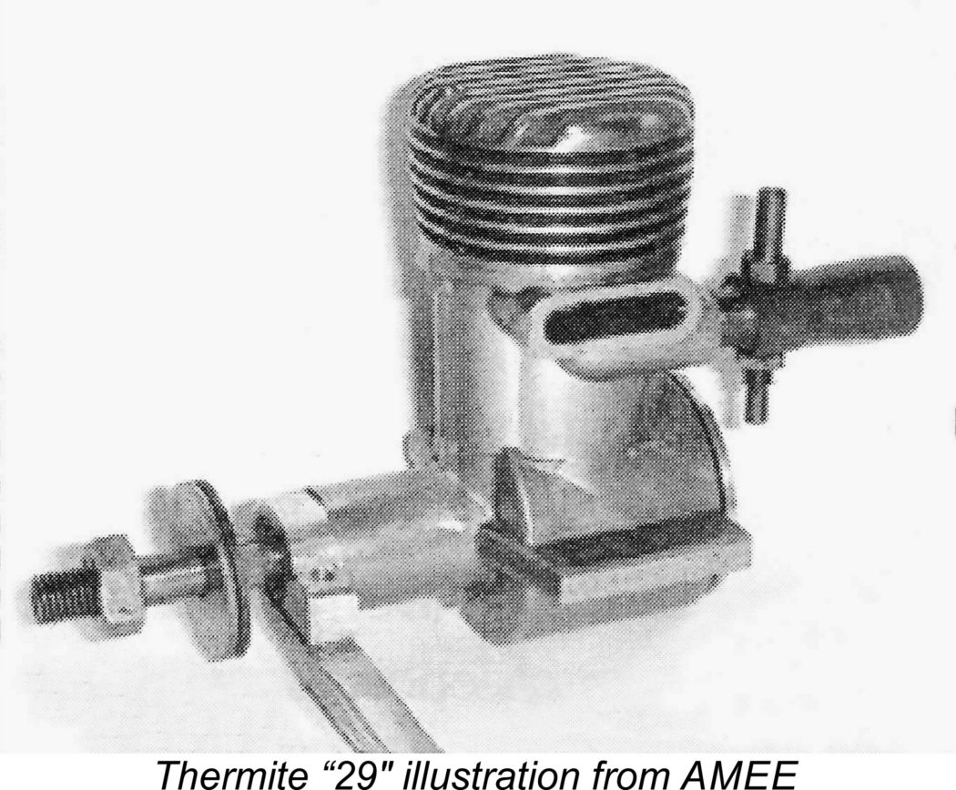 My own awareness of this ultra-rare engine was first stimulated by the fact that my late valued acquaintance and colleague Ted Enticknap had an example - the only one that I've ever encountered personally. This is the unit that appears as the Thermite 29 diesel on page 222 of the first volume of Tim Dannel's indispensable “
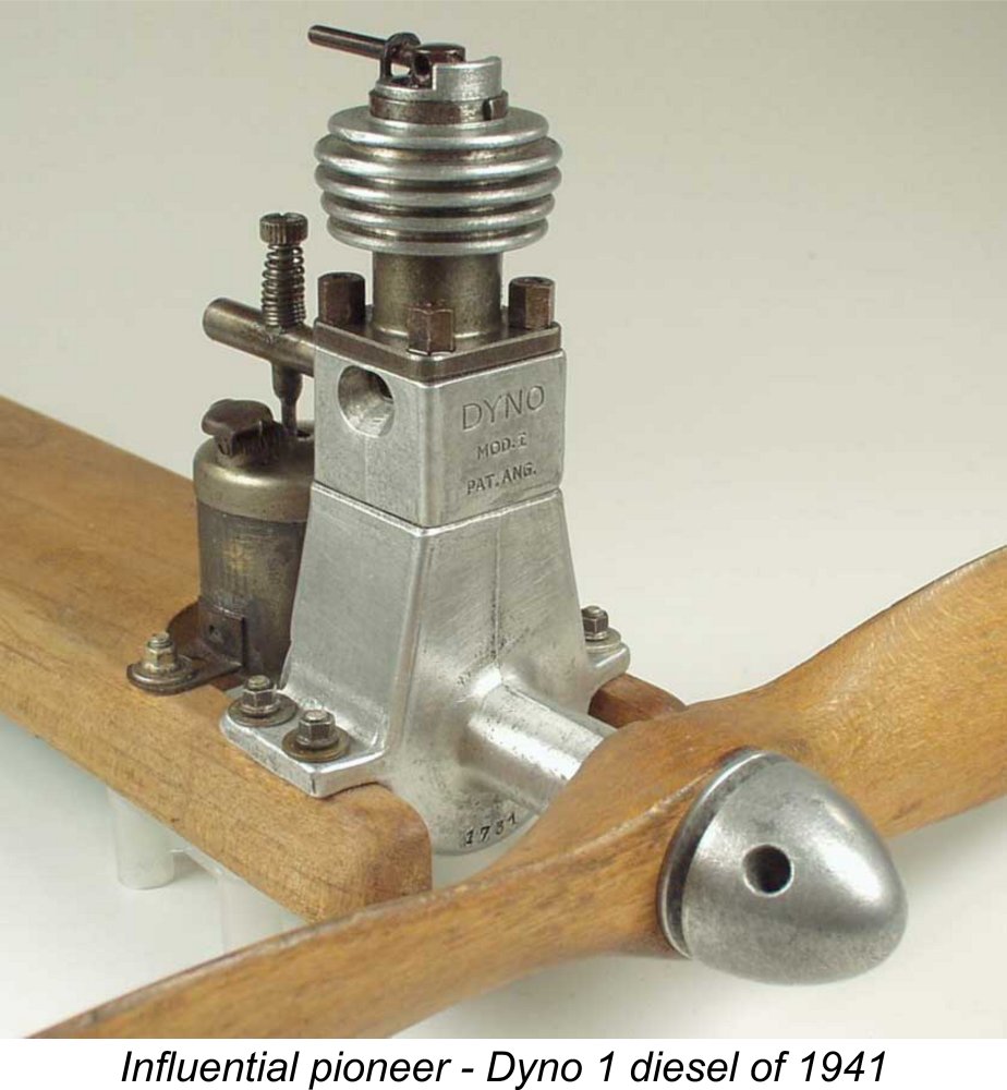 The model diesel (or more correctly, compression ignition) engine was a wartime European innovation which entered a rapid and very productive development phase in the years immediately following the conclusion of WW2. At the time in question, the commercial establishment of the miniature glow-plug by
 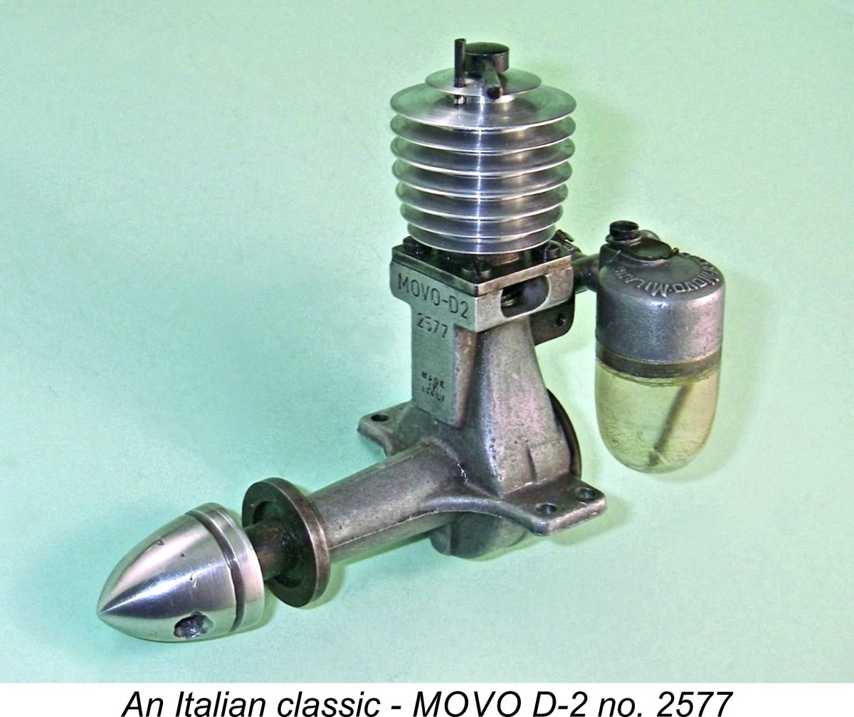 An informative article on diesels by Jim Watson which appeared in the March 1946 issue of ”
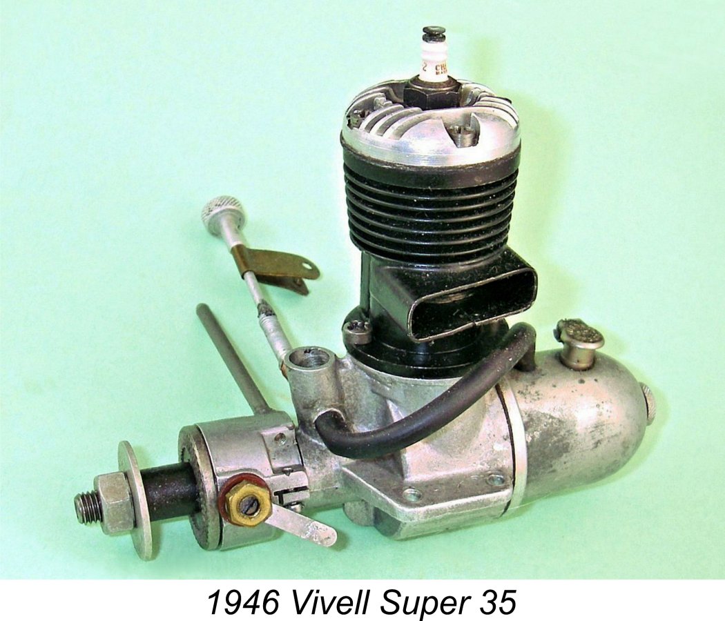
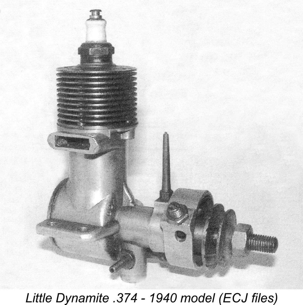 One of those who clearly sat up and took immediate notice of the new technology was Jim Brown of Oakland, California, maker of the Thermite series of model engines and later responsible for manufacturing certain members of the
 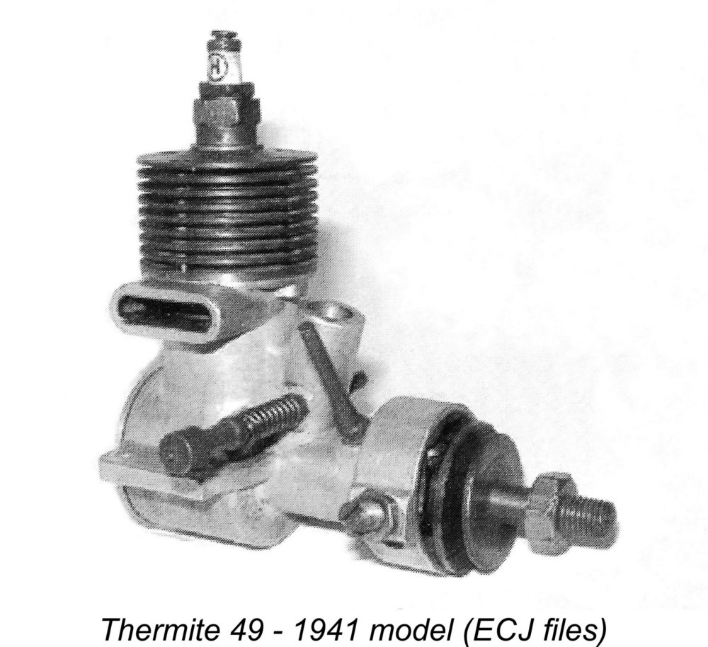 a cleanly-designed FRV model which was basically a .49 cuin. design but was actually offered in several displacements. It later became the prototype for the Vivell "Forty-Niner" sparker of 1946. A .588 cuin. FRV model was also added to the Thermite range in 1941.
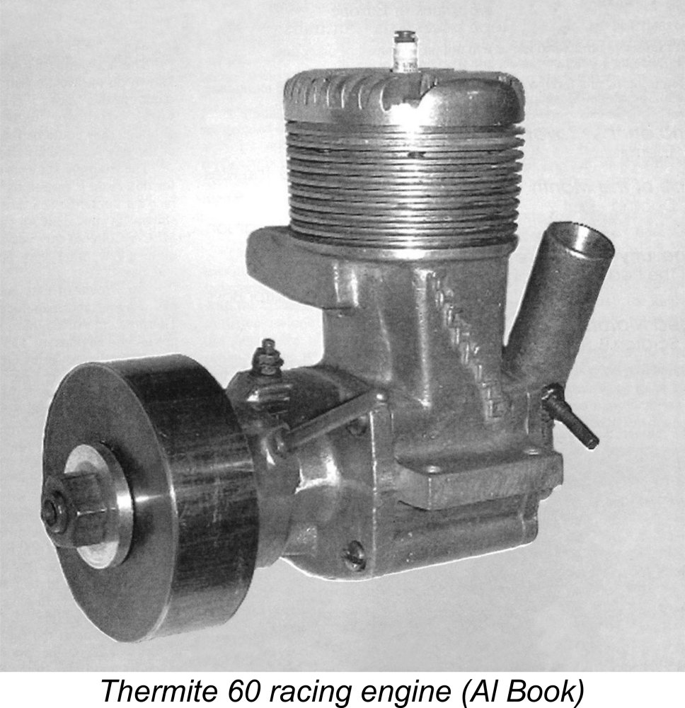 Models which appeared during the war years included an improved version of the .588 cuin. FRV model in 1942, followed by a .604 cuin. rear drum valve race car engine in 1944. The latter model was offered in both battery-supported and magneto-equipped versions. It was also the only Thermite model to actually display the name Thermite, which was cast in relief onto the bypass passage. Production of the .49 model and its derivatives also continued at a relatively modest rate during these years.
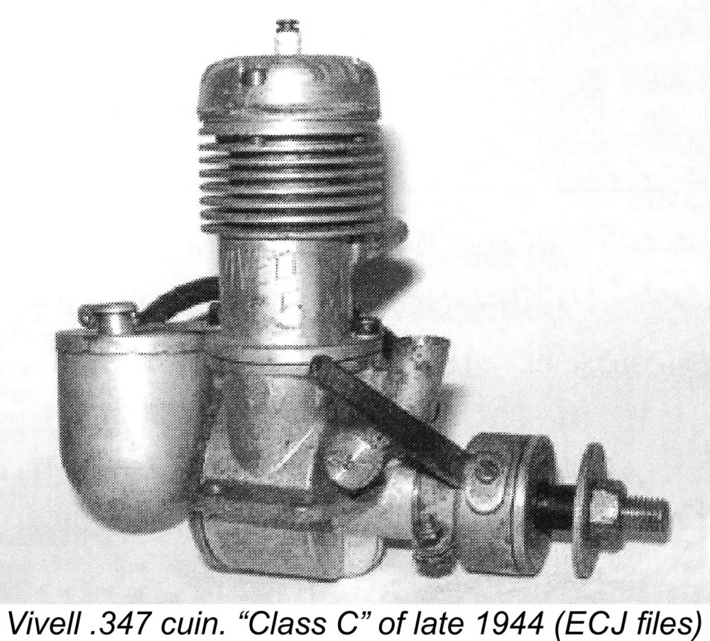 The result was the .347 cuin. Vivell "Class C" FRV design which was a derivative of the earlier Comet 35. This was supplanted in 1945 by the Vivell 35, which really set the Vivell range on the road to marketplace success. These engines continued to be manufactured for Vivell by Jack Keener.
 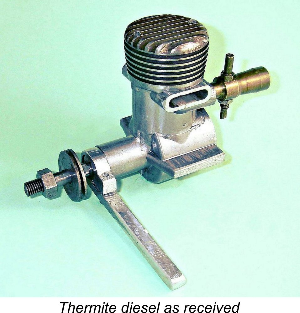 As received, this particular example of the Thermite diesel was missing the prop driver and needle but was otherwise in new condition apart from one clearly non-original feature to be discussed below in its place. None of the components bore any marks of previous use apart from some minor scuffing on the backplate inner face, perhaps indicative of a little turning-over by hand.
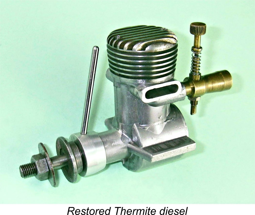 and the old abacus stubbornly cling to these numbers! So this example of the Thermite 29 (as it was presented by
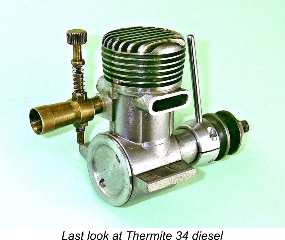
 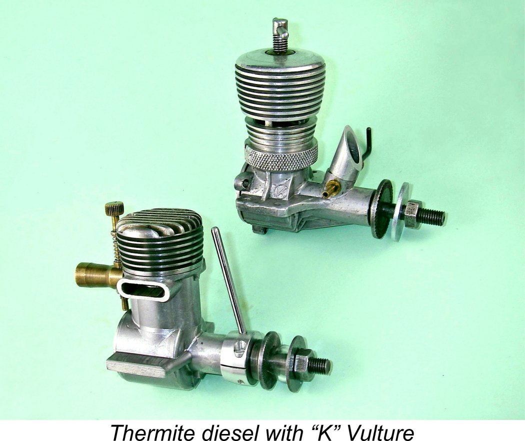 The Thermite 34 (as we must now call it) is a very neat and compact design for a diesel of its displacement, weighing in at a commendably light 8.36 ounces (237 gm) in its restored running condition as illustrated. This is actually quite comparable with the later British 5 cc “
 Pursuing this train of thought, I must confess to a strong feeling that the "modified die" scenario does not provide a fully satisfactory explanation of the use of a permanent mould casting for such a low-production engine. Even the modification of an existing die would involve an investment of time and effort that appears to me to be inconsistent with the seeming goal of limited production of what must surely have been viewed as an experimental design. The fact that Jim Brown was already heavily committed to the manufacture of the Vivell range as of late 1945 would surely have left him with insufficient spare time to put this level of effort into a trial model which stood well apart from the mainstream Vivell production program.
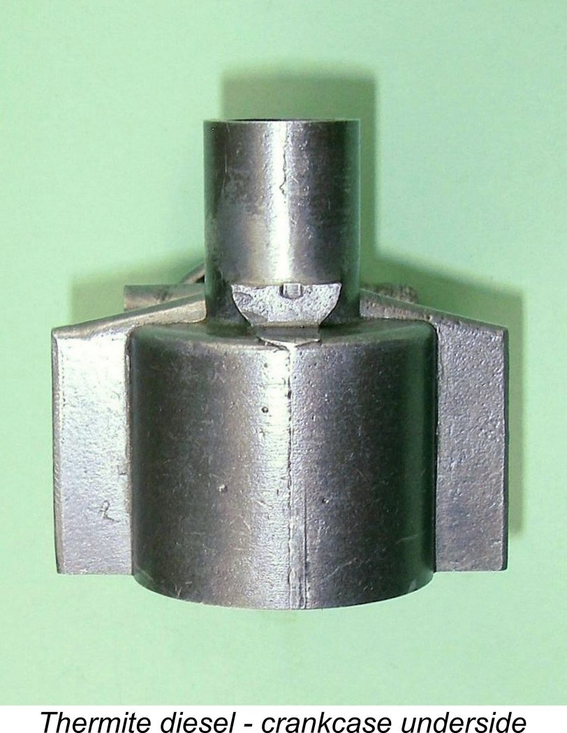 One very intriguing feature of this particular casting is the fact that the mounting lugs are un-drilled. At first glance, this might be taken to imply that the intent was to allow the owner to drill the lugs at a spacing which would allow the engine to become a bolt-in replacement for a previously-used model from another manufacturer. However, it seems to me to be far more likely that this example was a prototype constructed strictly for testing purposes - you don't need drilled lugs to mount an engine in a test stand.
 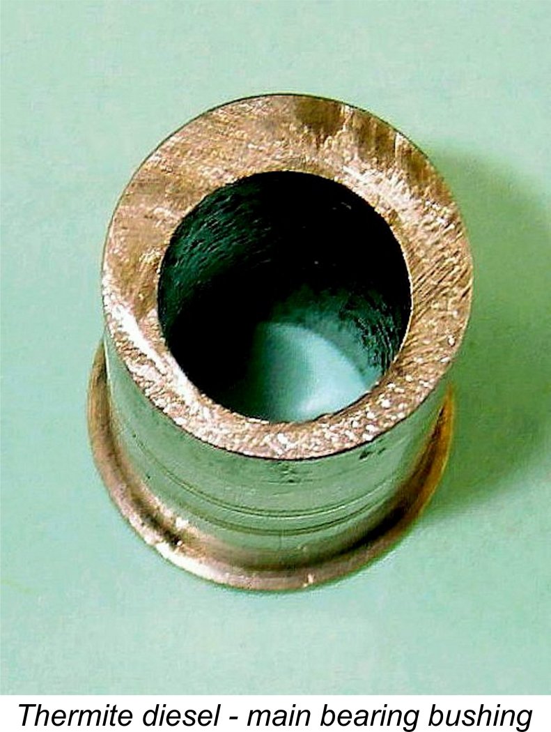 It turns out that the Thermite is an early example of the application of the eccentric-bearing compression adjustment system. The main bearing is bored eccentrically (off-centre) through the tubular bronze bushing which serves as the main bearing shell. This bushing is a light push fit in the centrally-bored main bearing casting, leaving it well supported but still free to rotate within the casting. One end of the previously-mentioned arm is formed into a clamp which secures the arm to a protruding front section of the bushing, allowing it to serve as a lever for rotating the bushing in the case.
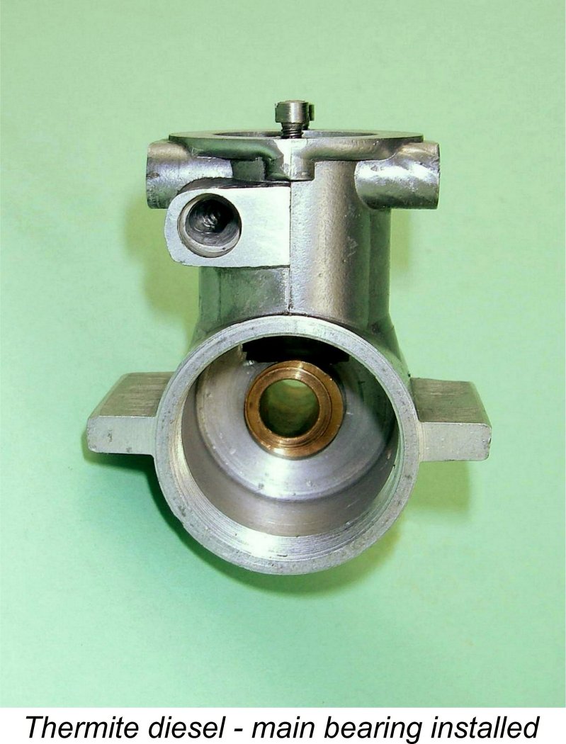
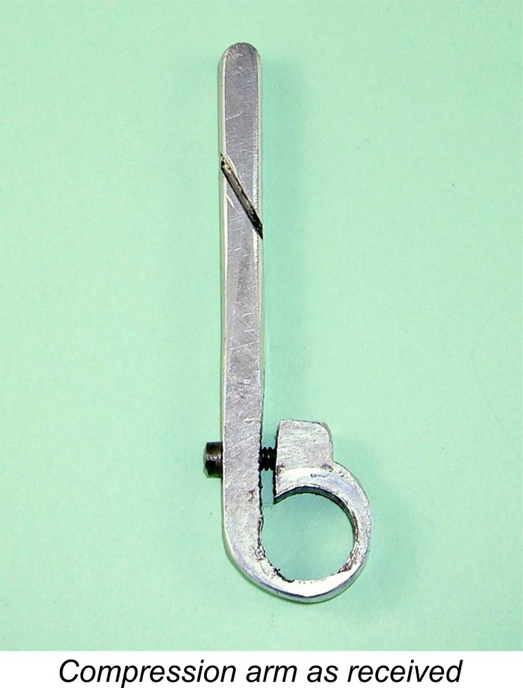 proportioned as well as coming far too close to the prop for safe operation. Most importantly, it lacked any means of providing some degree of friction between the arm and the main bearing housing, an essential feature if compression settings are to be held firmly given the inevitable tendency of the bushing to turn with the shaft due to friction drag.
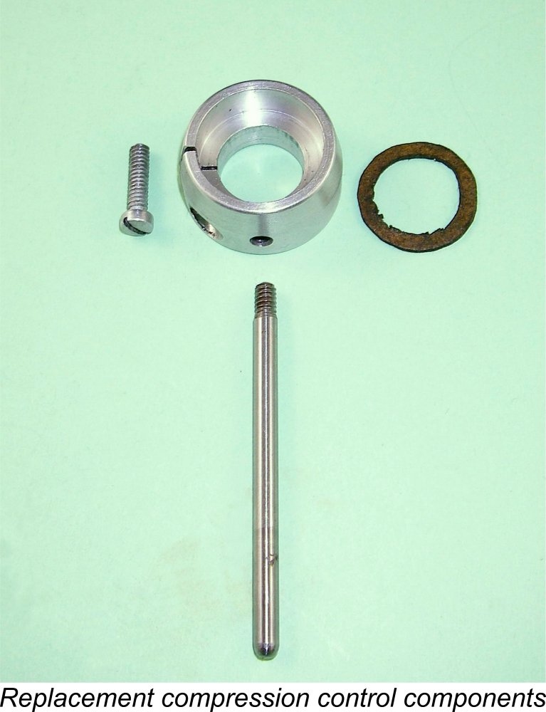
 The chief downside of the system is that adjustment of the compression ratio in this way also has the effect of altering the cylinder port timing. Advancing the ignition timing by raising the crankshaft to increase the working compression ratio also decreases both the transfer and exhaust periods while at the same time increasing the induction period. However, in a relatively low-speed side-port engine like this one, this is probably not a critical issue. The various moving-liner models like the
 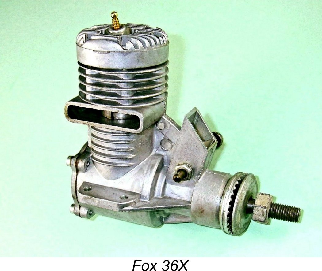 increase in the leverage applied by the piston to the crankpin on the power stroke together with concurrently reduced piston side-thrust and associated friction losses. It also promotes a measure of additional piston “dwell” at the top of the stroke, which can offer combustion benefits in addition to lengthening the angular duration of the power stroke by comparison with the compression stroke.
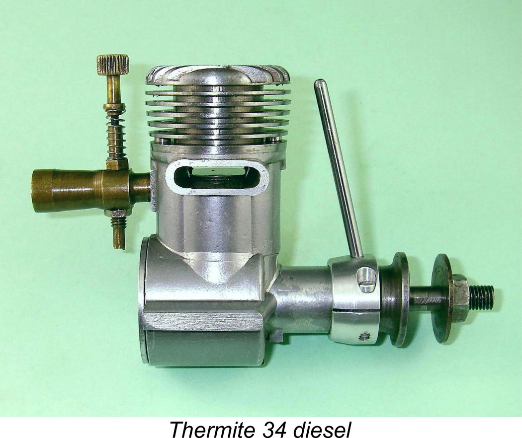 The problem with this approach is that the compression lever will then function in the opposite direction to the timer arm of a spark-ignition engine - to increase compression, thus advancing the ignition timing, one has to rotate the bushing in the direction of normal engine rotation. Considerations of operational familiarity for spark ignition users might thus suggest that the bushing should actually be fitted with the bearing offset to the right, which will give the reverse of the ideal desaxe geometry but will make the compression arm operate in exactly the same manner as a spark ignition timer arm - increased compression and hence more advanced ignition timing will result from rotating the bushing in the opposite direction to normal engine rotation.
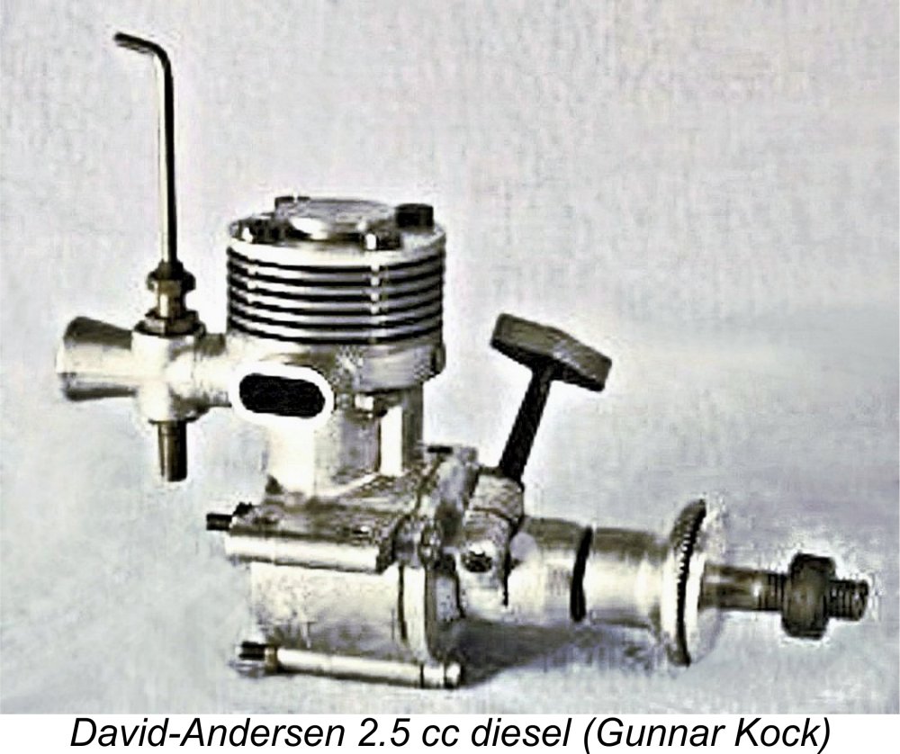 It's actually both fascinating and quite unexpected to find such an early American diesel using the eccentric-bearing compression adjustment system. Those engine aficionados who remember this relatively uncommon system at all generally associate it with the
 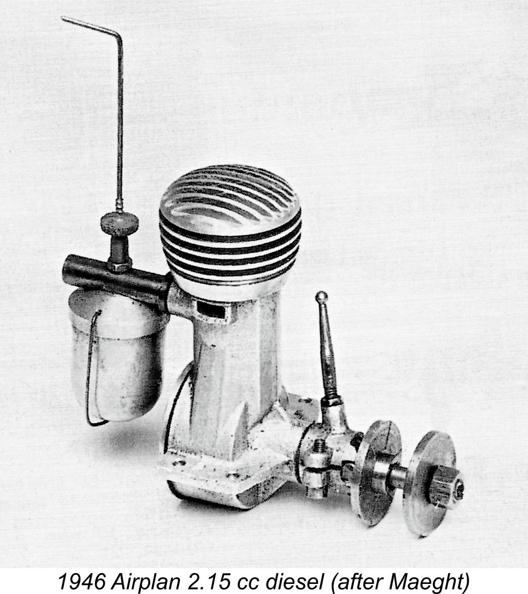 used conventional vernier compression adjustment in his earliest designs. His well-known 2.5 cc eccentric-compression diesel which is illustrated above did not actually enter production until 1950, becoming the last such design to do so.
 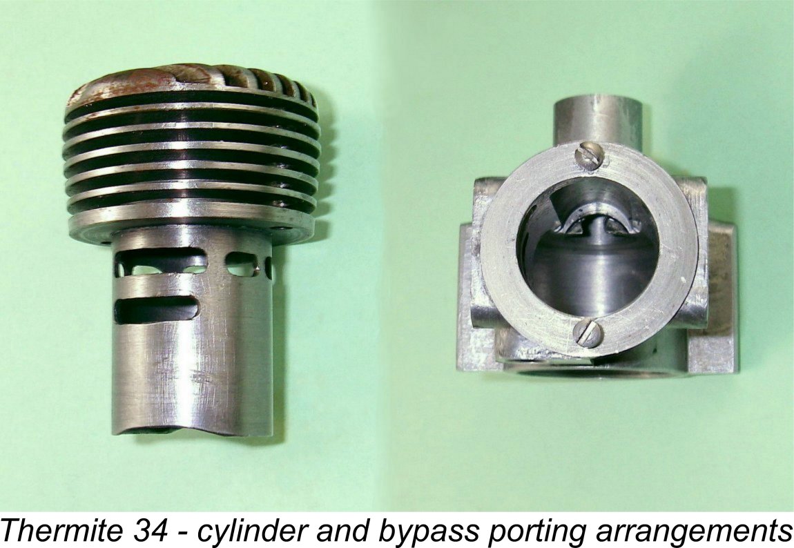 Once one realizes that we are dealing here with an engine which was obviously the subject of some highly original thinking, we are no longer all that surprised to find upon closer examination that it is in many ways a very advanced design indeed in the context of its time. For starters, the porting is unusually well developed for a side-port unit. There are two milled exhaust ports placed opposite one another at the sides of the engine and discharging through an opposed pair of stubby exhaust stacks. Two pairs of generously-dimensioned milled transfer ports are located fore and aft between the exhaust ports. Unusually by the standards of the day, these ports overlap the exhaust almost completely. The same system that was later to be applied so successfully by the likes of Cox, Holland,
 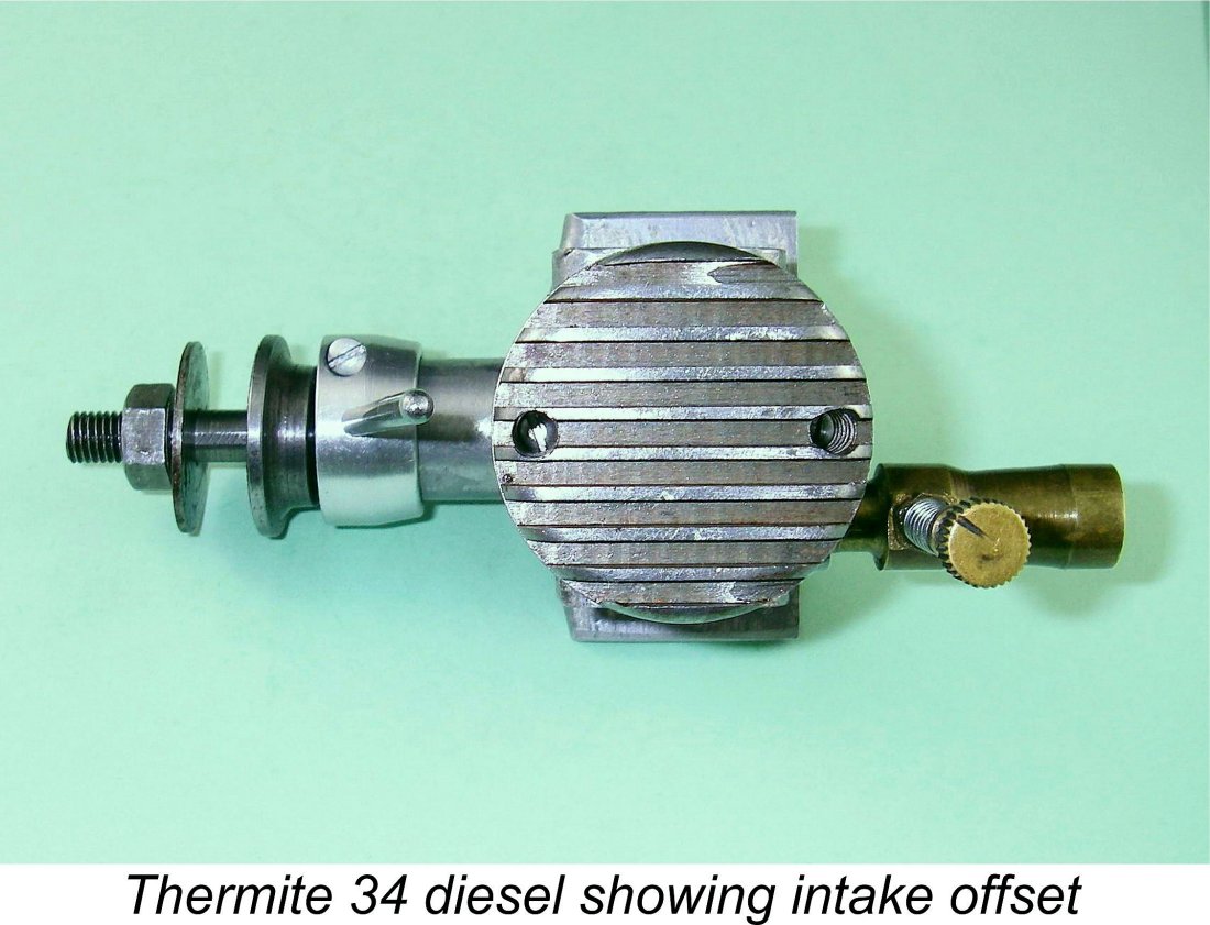 Given that this is a side-port design, the presence of the fore-and-aft transfer ports and bypass passages naturally dictates that the induction port be located at the side between them. The Thermite's generously-sized milled induction port is positioned directly below the left-hand exhaust opening (looking forward in the direction of flight). This necessitates the positioning of the cast intake boss and brass intake venturi well to the left-hand side of the engine.
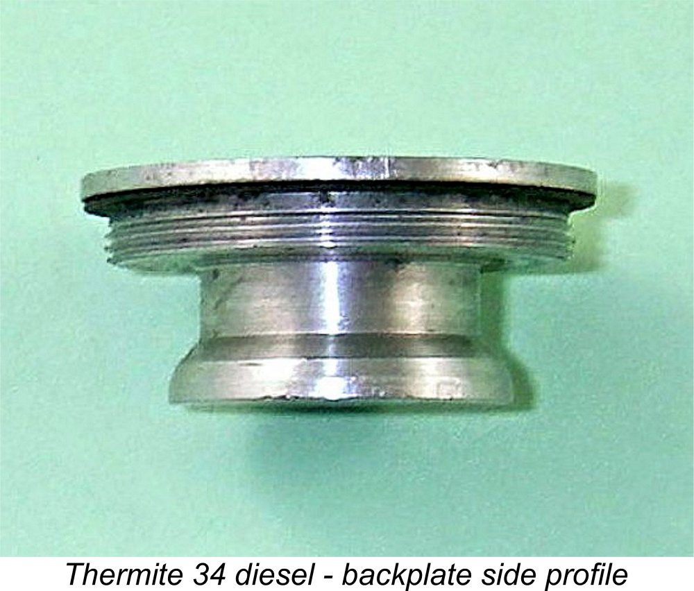 So much for what can be gathered from an external examination of the engine. To learn more, we have to remove the turned aluminium alloy screw-in backplate, which seals to the crankcase with a gasket. Upon doing so, we immediately encounter another interesting design feature. The diameter of the backplate thread is large enough that a full-diameter full-depth backplate would seriously obscure the rear bypass passage in addition to fouling the piston skirt at bottom dead centre. To get around this, the designer has reduced the diameter of the backplate beyond the threaded portion and has also cut a deep circumferential channel into the reduced-diameter section. This maintains unimpeded gas access to the rear bypass passage regardless of the orientation of the backplate when tightened, at the expense of some increase in crankcase volume. It also provides ample piston skirt clearance. More very clear thinking in evidence!
 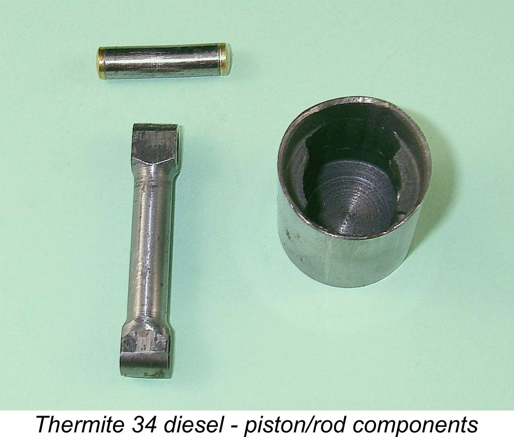 The lapped cast-iron piston is very well made and fitted indeed. It is extensively machined away internally to lighten, although quite substantial piston bosses are retained. Despite the machining efforts, the piston still weighs a very hefty 15 gm - high revs need not apply! The piston fit on this apparently unused example is in fact a bit on the tight side. The 3/16 in. dia. gudgeon pin is of tubular steel with brass end pads. The sturdy steel con-rod is very nicely machined from the solid. It is very closely fitted at both ends, with almost no discernable play.
 The hardened one-piece solid steel crankshaft is both cleanly machined and nicely finished. The web is a plain disc with no counterbalance features - a bit odd in view of the very heavy piston. Crankpin diameter is a somewhat skinny 3/16 in. - a larger diameter would inspire more confidence. One gets the impression that this shaft may have been designed originally for use in a spark ignition model.
 The major challenge with larger diesels from the vintage era is always achieving that initial start. The most problematic issue is the tendency for the very high compression resistance coupled with internal friction to "brake" the engine, thus discouraging it from carrying over from the initial firing stroke to the next. The result can be a series of pops and bangs with no actual start - extremely frustrating!
  Once the engine was running, I quickly had to back off the compression considerably as it warmed up. This is actually a very typical characteristic of large low-speed vintage diesels - they seem to like a lot of compression for starting and then require a significant back-off as they warm up. A fraction less than two turns of the needle was found to be a very consistent starting setting, with best running being established at around 1-3/4 turns. Suction appeared to be excellent.
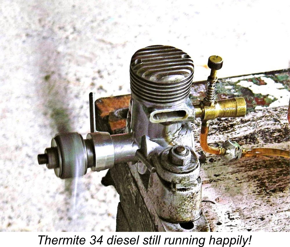 Optimum compression settings were very easily established since the control system proved to be highly effective in use, with excellent response from the engine. The needle too proved to be both responsive and non-critical, making establishment of the desired mixture very straightforward. The spring used for needle tension held the settings perfectly.
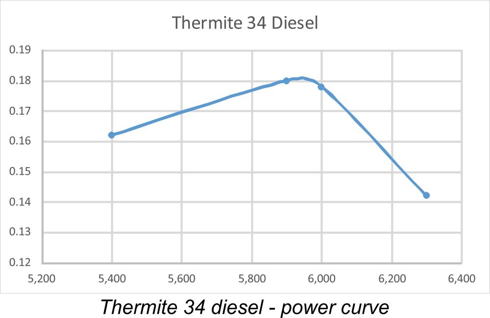 Tests on a couple of other props yielded 5,900 rpm on an APC 12x7 and 5,400 rpm on an APC 12x8, implying outputs at those speeds of around 0.180 BHP and 0.162 BHP respectively. Taken together, these figures seem to confirm that my chosen test props bracketed the peak very nicely - I saw no reason to continue the testing. The data suggest a well-defined peak at around 5,900 rpm, where the output is of the order of 0.180 BHP, with a sharp decline thereafter. The engine was evidently running at its peak on the bench using the 12x7, which would thus appear to be the ideal bench testing prop. Allowing for airborne pickup, a 12x8 or perhaps a 13x6 would likely have been the best prop to use for flying purposes.
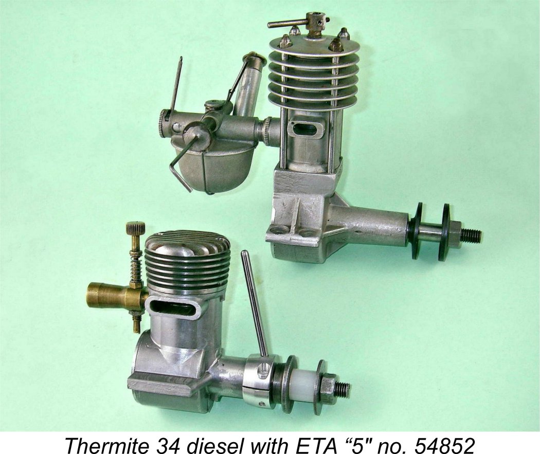 But in any case, the numbers aren't by any means dismal by the standards of 1945 or even those of a few years later - the highly-touted British
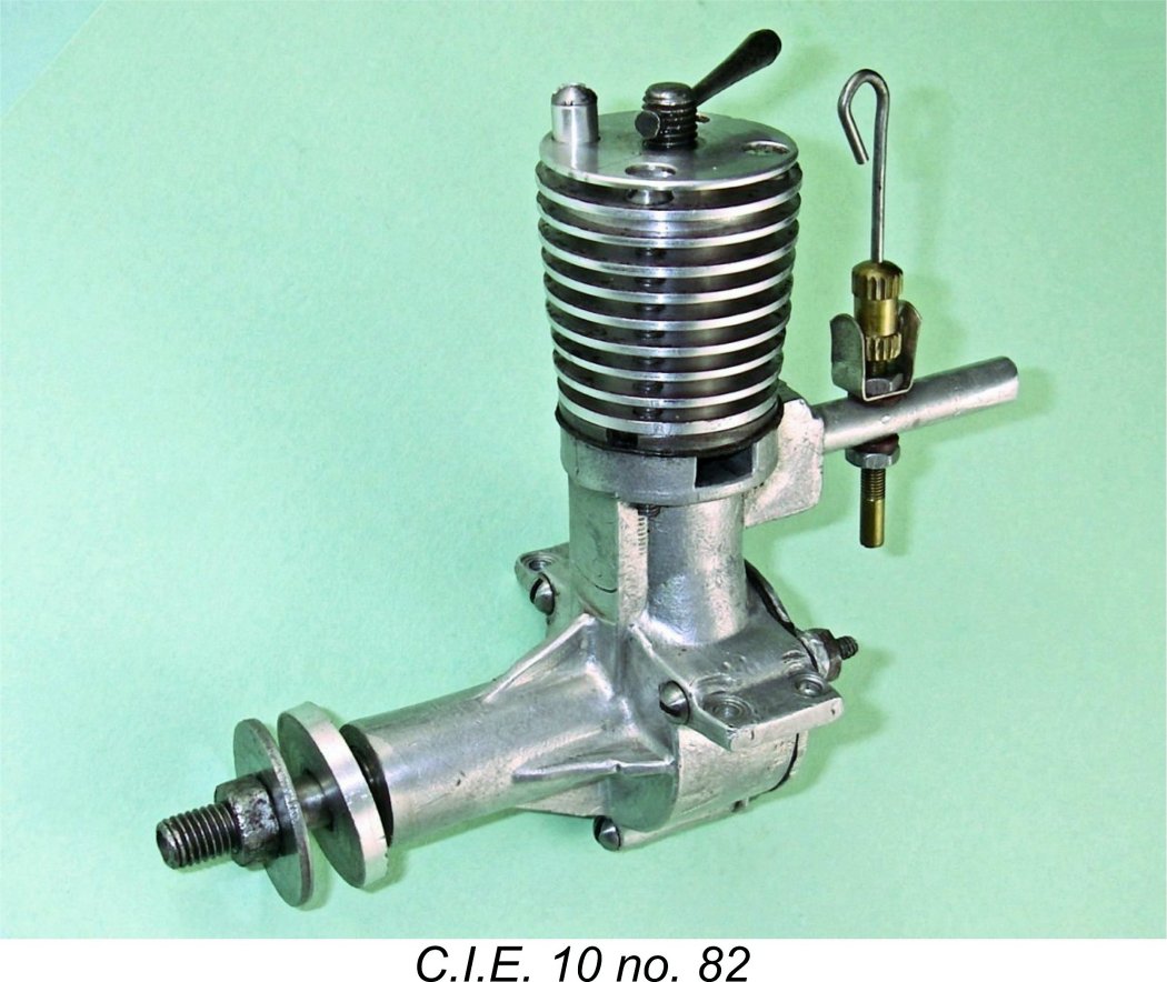
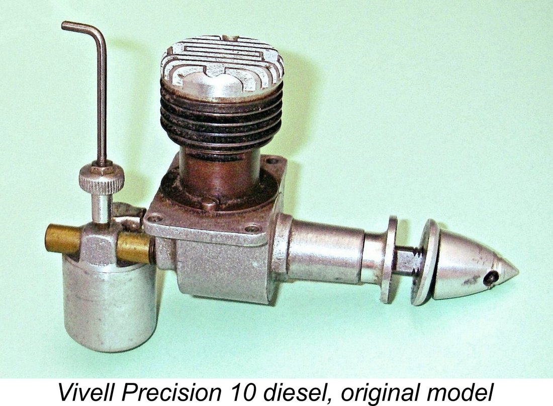 be a future for the model diesel in America. In 1947 (still prior to the commercial introduction of the miniature glow-plug, remember) he authorized Jack Keener to develop and manufacture a series of diesel models under the Vivell Precision designation. The extent, if any, to which Jim Brown was involved with the Vivell diesel project remains unclear.
 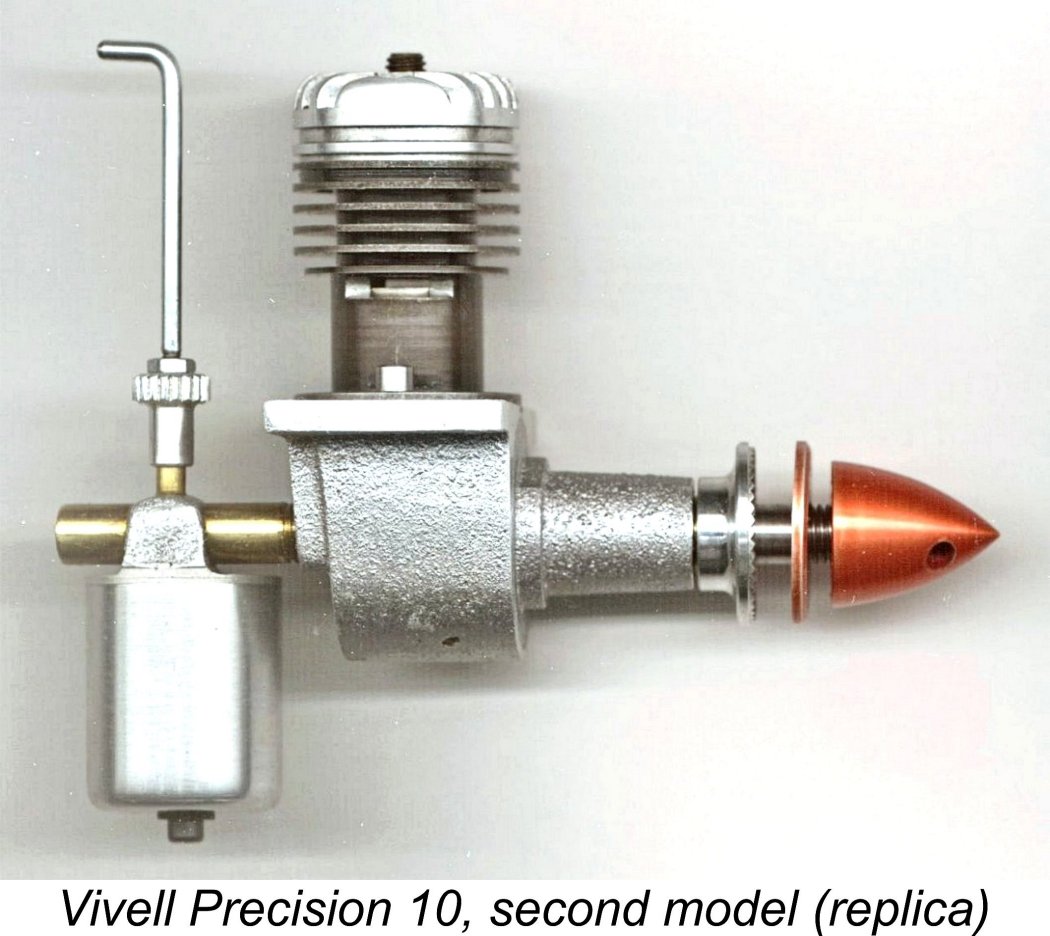 In 1948, a refined version of this engine appeared. This featured a head having deeper fins and incorporating a contra-piston inside the head (as opposed to inside the bore). Compression adjustment was controlled by an Allen-head screw. The variable-compression feature made this variant far more flexible as regards the range of fuels and props which could be used.
 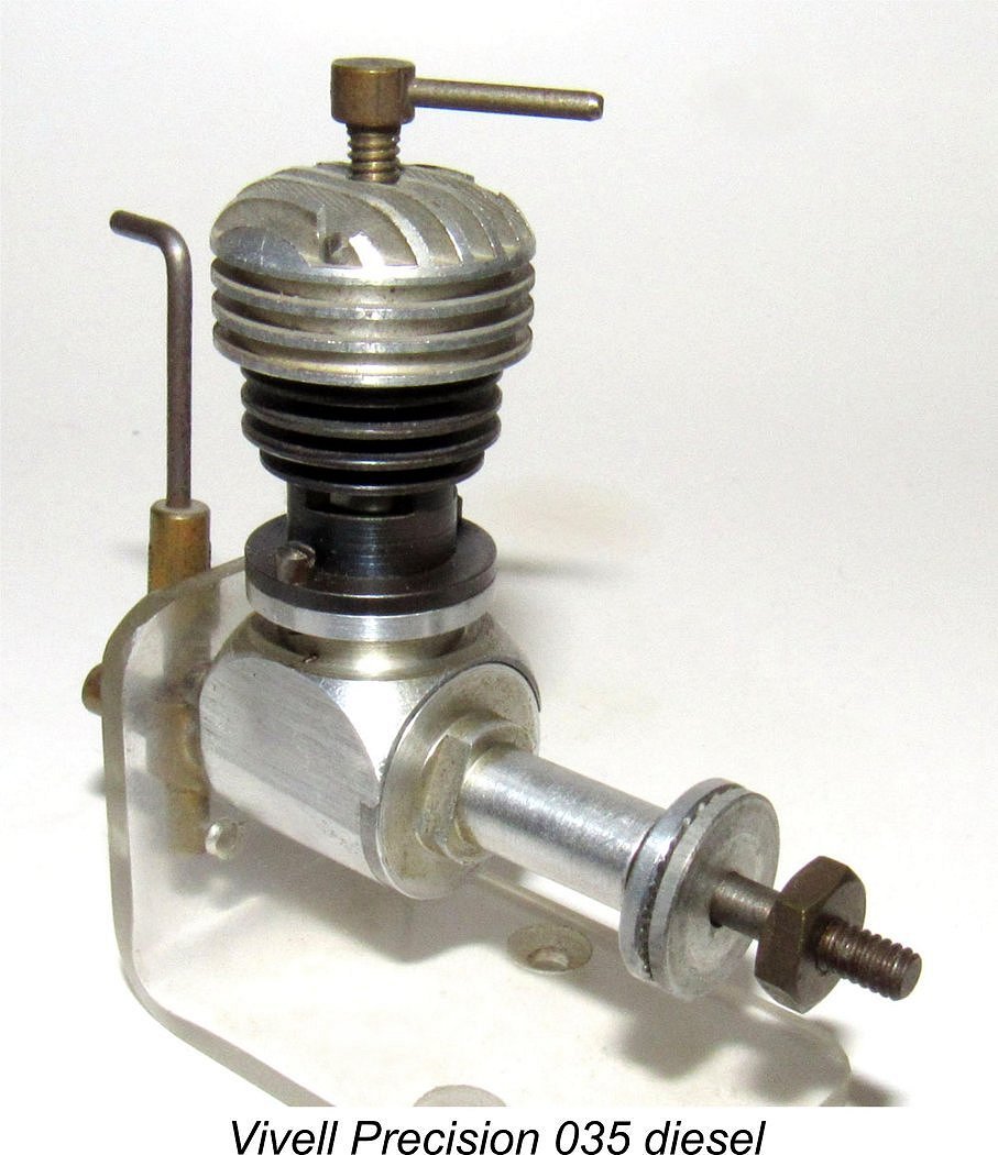 1948 also saw the appearance of a smaller variable-compression diesel model of basically similar design designated the Vivell Precision 035. This very compact and well-made .035 cuin. (0.57cc) unit did not use any castings, being machined entirely from bar stock. Although also an RRV design, it was set up exclusively for radial mounting direct to the rear of the crankcase, a configuration which actually posed significant problems for the user in arranging an appropriate mounting in a model since the mounting bolts had to be tightened from the rear, making the use of a separate mounting ring more or less mandatory.
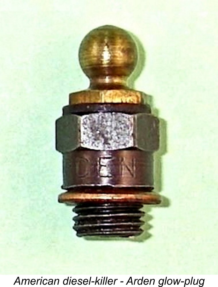
 I hope that you've enjoyed this look at a model diesel engine which not only possesses an unusual degree of technical interest but in addition can lay a very fair claim to being one of the very first new post-war diesel designs of them all. It was certainly the first such product from an established American designer.
 | |