
|
|
The M.E. Engines By Adrian Duncan with Maris Dislers
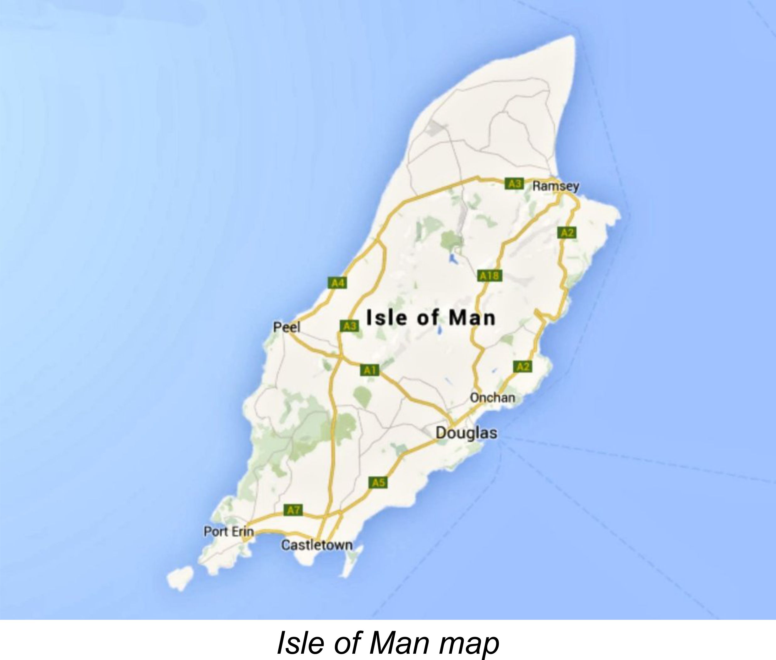
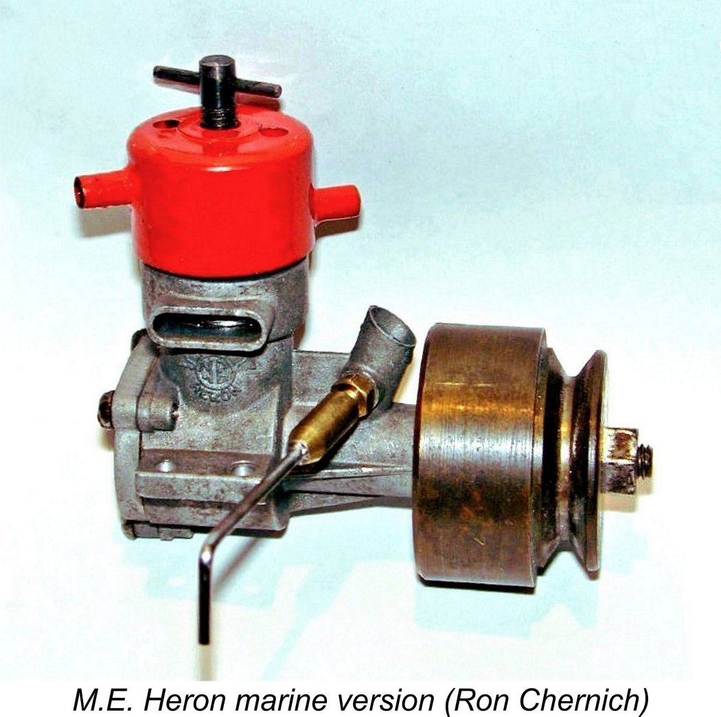
Apart from a number of published test reports and passing references in the modelling media, the only focused commentary of any note on the M.E. engines that I’ve been able to find takes the form of a 2007 write-up by my late and still much-missed mate Ron Chernich. That text focused to a great extent upon the restoration of an example of the 1 cc M.E. Heron marine variant which had come into Ron’s possession. Although a very useful reference upon which I These engines shared a common geographic origin with their better-remembered competitors from Davies-Charlton - as of the 1960's, both ranges were manufactured on the Isle of Man (IOM). Davies-Charlton had started out in 1947 from a base at Barnoldswick in Lancashire, England, but had relocated to the IOM in early 1955 both to deal with a production capacity issue and to take advantage of the various financial incentives then being offered by the Manx government. The M.E. range first appeared in 1960 to challenge its IOM competition. Given this commonality of geographic origins as well as the generally similar design layouts of their products, it’s perhaps less of a surprise than might otherwise be the case to learn that the two companies shared a common business origin as well. I’ve recounted this story in some detail in my separate article on the Davies-Charlton (D-C) range. For the reader’s convenience I’ll begin the present article by reviewing the key points which are relevant to the M.E. story. Origins
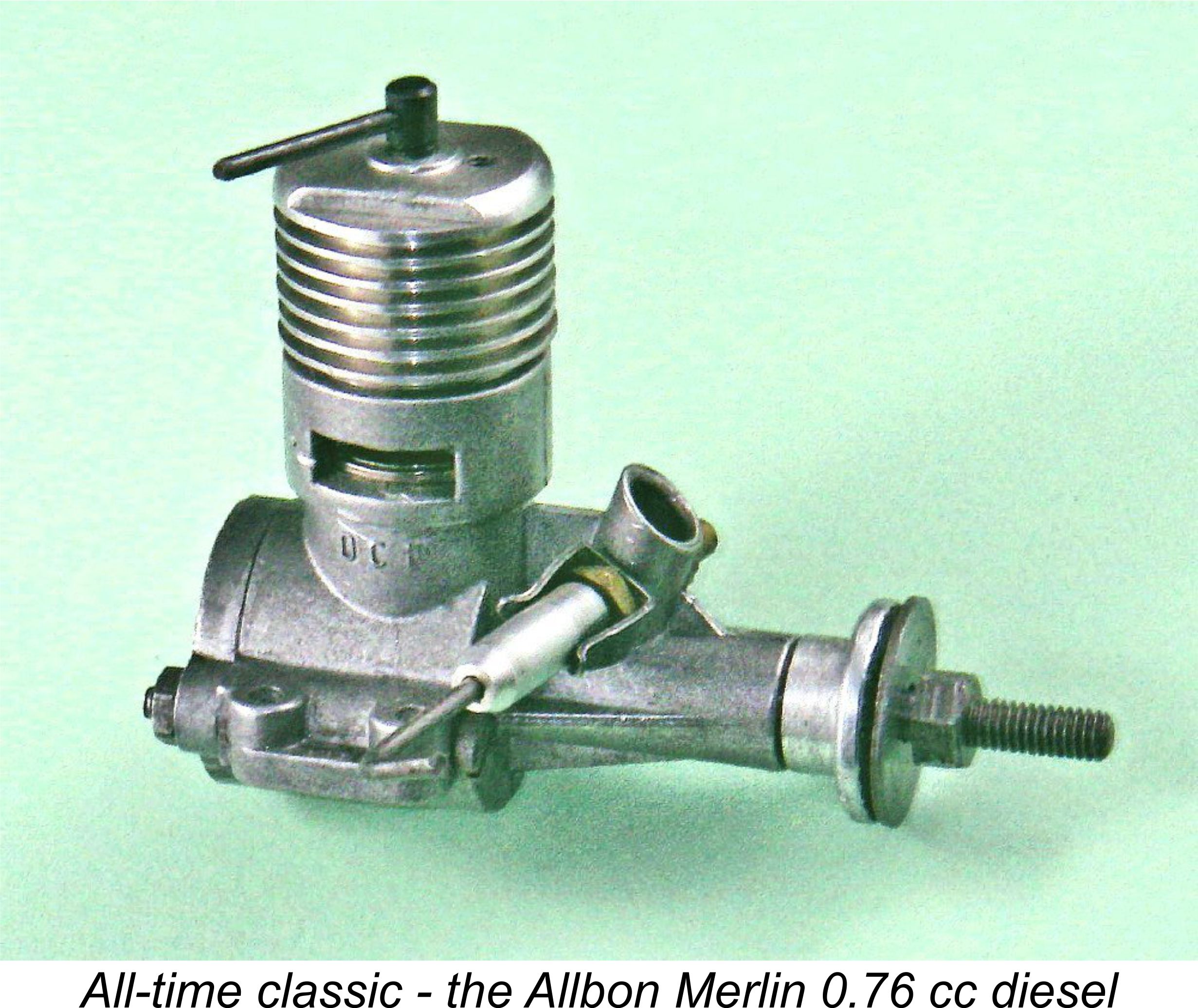
One of Davies’ early moves was to recruit fellow Rolls-Royce employee Walter Kendall to join him in the D-C venture. Like Davies, Kendall was a toolmaker by trade, thus unquestionably possessing precision engineering talents which would serve the new company well. However, Davies’ prime motivation was most likely the fact that Kendall just happened to be engaged to (and subsequently married) the daughter of the sub-contract manager for Rolls-Royce! From that point onwards, Kendall’s father-in-law routinely passed the pick of the sub-contract work to D-C Ltd., thus laying a firm foundation for the company’s later success. It appears that Davies had always seen the undertaking of custom precision engineering work for Rolls-Royce and others under contract as a cornerstone of his company’s broader long-term portfolio. Kendall’s arrival greatly facilitated the achievement of this ambition. During the early 1950’s the company’s expanding and very lucrative involvement with contract work through Rolls-Royce and others began to take up an increasingly disproportionate amount of Hefin Davies’ time, deflecting him away from the design of further new model aero engines. The D-C 350 which had This situation prompted a significant change in 1952 when Davies-Charlton progressively joined forces with Alan Allbon, who had been marketing his own rather more diverse engine line since early 1948 but had run into production difficulties along with financial challenges. An updated biography of Alan Allbon which includes a great deal of input from his sons Kenneth and Derek may be found elsewhere on this web site. The merger with Allbon allowed Davies to continue to lead the increasingly lucrative sub-contract work while Allbon assumed primary responsibility for the subsidiary model engine development and production programs. It also allowed the expansion of the Allbon range at production levels which could be tailored to meet demand. Hence there were clear benefits for both parties. Walter Kendall continued to be involved with the company at this point in time. Without exception, all those who knew him personally have consistently agreed that Davies was a very pushy individual with a short fuse who liked to be on top of everyone and everything at all times. These traits were combined with a This hadn’t prevented Allbon from fulfilling his end of the merger agreement by developing several best-selling new designs to be manufactured by D-C Ltd. under the Allbon name. A tipping point was reached in October 1954 with the appearance of the 0.76 cc Allbon Merlin diesel. The immediate sales success of this very popular engine created a serious production problem for D-C Ltd. It just so happened that this production crisis coincided with a number of initiatives on the part of the government of the IOM to attract industry to the island in order to alleviate a chronic unemployment problem there. Hefin Davies was quick to sense his opportunity. The IOM is part of the British Isles but is not part of the United Kingdom, having its own laws and government under the ultimate authority of the British Crown. It is in fact At the time in question, the Manx government was making a determined effort to attract investment and jobs to the island, offering tempting incentives to mainland companies who might be willing to relocate. Davies was quick to take full advantage of these incentives, despite the fact that it meant abandoning most of the employees who had contributed so much to his success up to that point. He moved ruthlessly to complete the move, resulting in Davies-Charlton’s model engine manufacturing activities being relocated wholesale to Hills Meadow, Douglas by June of 1955. Since the deal with the IOM government stipulated that the vast majority of jobs had to be assigned to existing IOM residents, this left most of the Barnoldswick staff who had loyally helped to build the company without jobs. Alan Allbon and Walter Kendall were among the few who were permitted to relocate with Davies to the IOM at this time. However, Allbon was now actively seeking an escape from his increasingly poisonous relationship with Davies. This led him to complete his own negotiations with the Manx Government which saw him established in the latter half of 1955 as an independent precision engineering contractor at separate premises in Douglas. From that point onwards, Allbon had no connection with D-C Ltd. His place as Works Manager was taken up by one Ted Saunders.
However, Allbon’s continuing enthusiasm for model engines led him to persuade his less enthusiastic partner to agree to the development and manufacture of the excellent little Allbon-designed 0.55 cc A-S 55 diesel beginning in late 1959. I’ve recounted that story in detail elsewhere. Returning to the IOM, Walter Kendall still soldiered on during this period. However, it seems likely that he too was having increasing difficulty maintaining a good working relationship with the irascible Hefin Davies. The record shows that no-one ever managed to maintain a smooth collegial relationship with Davies for any length of time - Kendall actually appears to have lasted longer than most! In addition to any such tensions, it may well have begun to rankle with Kendall that his marital connection with Rolls-Royce management was being used to funnel contract work into Davies' company rather than his own.
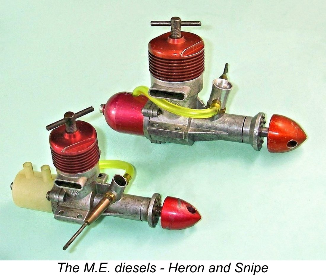
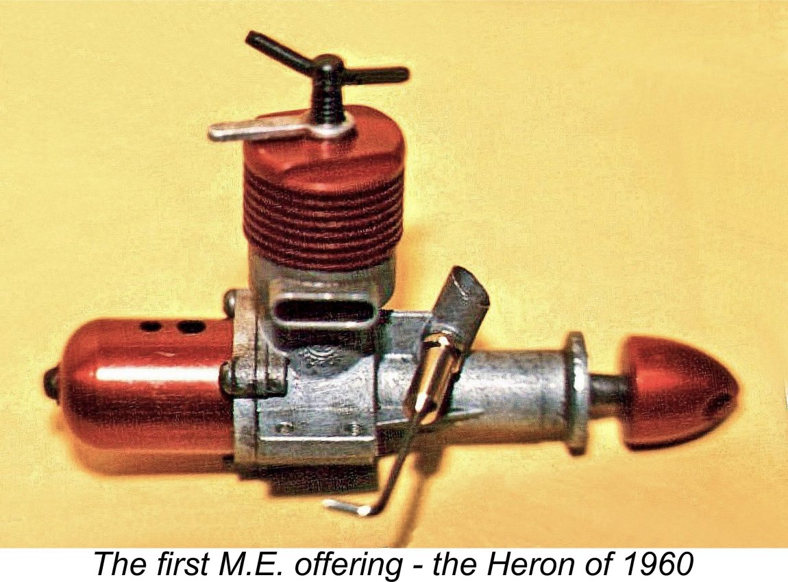
Before proceeding to a discussion of the M.E. engines, it’s worth taking a little time to consider the impact of these various defections on the business prospects of D-C Ltd. In losing Alan Allbon, Hefin Davies lost by far his most experienced model engine designer and manufacturing specialist. Allbon’s replacement Ted Saunders was a capable enough manager, but lacked Allbon’s technical skills. Saunders’ managerial talents were also lost to the company in early 1959 in any case. Walter Kendall doubtless possessed engineering talents which could have served Davies well. However, he too departed in 1959, leaving a vacuum which It seems to me that the situation just described could explain three things - one, the increasing prominence of model engine manufacturing in D-C. Ltd.’s business portfolio; two, the steady erosion of the quality of D-C Ltd.’s products which began to become noticeable at around this time; and three, the almost complete design stagnation of the D-C range from 1959 onwards (the D-C Wasp .049 of 1971 was the sole exception). It’s impossible to avoid the conclusion that Hefin Davies’ inability to sustain a collegial working relationship with his talented associates played a major role in the emergence of all of these trends. Beware the enemy, particularly the enemy within! Now let’s return to our main subject here - the M.E. engines. Since it was the first model to appear under the M.E. trade-name, we’ll begin with the 1 cc Heron which appeared in June 1960. The M.E. Heron - Description We may well imagine that Hefin Davies was far from best pleased by the appearance of the Heron. Apart from the fact that it had been developed by a former employee and (presumably) colleague of his, the design of the Heron displayed clear evidence of its D-C ancestry! Although it was instantly distinguishable from its D-C competitors thanks to its twin exhaust stacks, there’s no denying that it followed the same basic design layout.
A number of contemporary commentators recorded Walter Kendall's strongly-held belief that good starting was assisted by maintaining better crankcase (primary) compression and that this could be both achieved and sustained through the use of a close fitting and long-wearing bushing supporting a hardened shaft of substantial length. To this end, the Heron featured a Meehanite cast-iron bushing which was honed to a very close fit on the hardened steel shaft. To keep weight down, the bushing was made very thin, leading to a strong likelihood of distortion if it was pressed in conventionally. To prevent distortion during assembly, the light alloy case was pressure die-cast around the bushing. This conferred the additional advantage of reducing the number of operations and set-ups required to finish the cases. It should be noted that cast-in bushes were not a new innovation, having been used in a number of earlier US engines such as the fixed compression Mite diesel. In his review of the Heron which appeared in the August 1960 issue of “Aeromodeller” (see below), Ron Warring observed that the closeness of the fit combined with the long-wearing nature of the cast-iron bush might impose an extended break-in period, which could be as long as eight hours before peak performance could be expected! The comment may be made that an 8-hour break-in period is a lot longer than most customers would find acceptable. However, the engine would doubtless perform quite well enough for most purposes long before that ultimate peak was reached. Indeed, Warring’s test confirmed this. The rest of the engine was basically quite conventional. Bore and stroke were 0.424 in. (10.77 mm) and 0.420 in. (10.67 mm) respectively for a calculated displacement of 0.0593 cuin. (0.970 cc). The engine weighed in at 2.65 ounces (75 gm) complete with tank.
The Heron’s cylinder design was very standard for sports engines of the period, featuring an expanded-diameter exhaust port belt which doubled as the cylinder locating flange. Three sawn exhaust ports were formed in this port belt, with three sawn transfer ports located directly beneath the belt. Such an arrangement provides unavoidably mild transfer timing since no overlap between exhaust and transfer ports is possible - the exhaust must be fully open for a considerable period before transfer can start, significantly limiting the available transfer period if the exhaust timing is to be kept to a reasonable value. The liner was located in the case both vertically and axially using the exhaust port belt as the locating flange. It was held in place by the screw-in cooling jacket described earlier. The smaller-diameter portion of the liner below the flange was positioned in an oversize bore in the crankcase to create a 360 degree bypass passage feeding the three transfer ports. The crankcase, backplate and prop driver were all very cleanly pressure die cast, being sand-blasted to a smooth and very attractive matte finish. Delicate engraving of the die placed the "winged M.E." logo with the word "Heron" in curved text under it on the right side of the case; the left side carried the text "MADE IN IOM". There was no serial number - indeed, such numbers were never applied to any variant of the M.E. diesels of either displacement. The backplate was secured by three short 6 BA machine screws and was relieved on its upper side for piston clearance at bottom dead centre. The presence of the three lugs which accommodated the backplate retaining screws opened up the possibility of mounting the engine radially. The backplate incorporated a tapped central spigot for the long 6 BA tank retaining screw.
The rod was a typical British "dog-bone" type turned from aluminium alloy. It was joined to the piston by a fully-floating gudgeon (wrist) pin of 1/8 in. diameter. Since the ends were rounded and the port slits were shallow in comparison, no great danger existed that any fouling of the ports could occur. The one-piece steel crankshaft was completely conventional. It was case hardened and ground with a full disc web displaying no attempt at counter-balancing. The jury is still out on this issue, at least for small "sport class" diesels. It appears that the benefits of counter-balancing decrease with decreasing displacements. Some successful designs incorporated this feature, while others didn’t. The prop was secured by a neat streamlined spinner nut which engaged with the 2 BA threaded shaft extension at the front. At the rear, the engine was provided with a nicely-made alloy fuel tank which was secured using a single central 6 BA screw. Both tank and spinner nut on the original examples were anodized red to match the cooling jacket. Both of the British aeromodelling periodicals of the day were quick to get their hands on test examples of the Heron. Let’s see how the engine fared in their hands! The M.E. Heron on Contemporary Test
Warring went on to praise the engine’s handling, characterising it as “an easy starter - probably the easiest of any diesel of its size”. He also found the Heron to be unusually insensitive to maladjustment of the controls - an ideal trait for a beginner's engine. The sole reservation expressed by Warring was the possibility that the very close-fitting main bearing might impose an unusually lengthy running-in period on some examples of the engine. However, he found that his test example appeared to be perfectly fitted as received, showing no measurable improvement over the approximately one additional hour of running to which it was subjected following completion of the test. He commented quite rightly that the use of a steel shaft in a cast iron bushing should result in an extremely long-life bearing. The important thing was to get the fit right as first assembled.
Warring summed up the Heron as “a first-class engineering job throughout with excellent handling qualities and the sort of workmanship that one does not often associate with “sports” engine production”. His final comment was that “anyone finding difficulty in starting the Heron can take consolation from the fact that it is his own fault and not the engine’s”!
Chinn noted that the Heron was “clearly aimed at the “popular” market”. He felt that the engine’s “modest price and easy handling characteristics” would help it to gain a foothold in this market sector.
Starting was characterized as “good - not perhaps the most foolproof we have experienced, but certainly among the best”. An extended running-in period produced no measureable improvement in performance, seemingly confirming that the bearing as supplied was very well fitted. In performance terms, Chinn measured a peak output of 0.072 BHP @ 11,500 RPM - exactly the same output as reported by Warring, but at a somewhat higher speed. Maximum Brake Mean Effective Pressure (BMEP) was measured as 49 PSI @ 7,500 RPM - a reasonable figure for a simple sports diesel. Chinn agreed with Warring’s recommendation of an 8x4 prop as an appropriate general-purpose airscrew. He summarized the Heron as “a docile well-behaved motor (which) should give excellent service”. OK, now we know what the contemporary testers of the day thought about the Heron. How does it stack up today, 60 years on? To find out, let’s turn the pen over to Maris Dislers for a present-day reappraisal! The M.E. Heron Revisited by Maris Dislers Why re-test an M.E. Heron, when Messrs. Warring and Chinn had already done that back in 1960? Perhaps because at first sight there seems little reason why it should produce only marginally more power than a typical E.D. Bee. The porting numbers are admittedly somewhat conservative - exhaust period 145 degrees, transfer period 80 degrees, intake period 125 degrees (opens 65 ABDC, closes 10 ATDC). Peter Chinn measured 155 degrees intake from 55 ABDC to 30 ATDC on his early version. Yet the transfers have almost double the area of the exhausts, while the effective choke area of 4.3 mm2 is also generous. Our test engine was a later example made by Moore Engineering (see below), with a steel cylinder but without the highly-touted cast iron crankshaft bushing. It came from Allan Laycock, looking almost new. He’d mentioned that it seemed a bit stiff, but freed up after soaking out accumulated castor oil residue in a jar of acetone. Early during testing though, it became quite evident that the engine was unhappy - it wouldn't tolerate speeds over 9,000 RPM, and then only with a generous mixture setting. Allan wasn’t kidding! Back in the workshop, a full disassembly revealed clear signs of a lack of lubrication to the front of the crankshaft journal, to the point that a speck of aluminium had attached itself to the crankshaft. This is a not-uncommon issue with tightly-fitted shafts where the oil has effectively been squeezed out by inadequate clearance. The fix was setting up in the lathe to polish the crankshaft journal and then clean up the crankcase bearing. This treatment added around 10 microns (.0004 inches) to the clearance. With both components dry, the crankshaft must fall easily into its bearing and spin reasonably freely if the fit is right. After the above treatment it did so, albeit remaining on the precision-fit side rather than the lowest-drag racing setup. What a transformation! The re-fitted Heron now ran happily right across the speed range and delivered good performance data. Our general-purpose test fuel of 25% castor oil, 30% ether, 45% kerosene plus 1.5% ignition improver seemed OK, but the engine could doubtless have benefited from looser fits to accommodate the castor oil film thickness. It's perhaps no coincidence that the instructions suggest a mineral oil fuel mix. This is not really a problem when running, but having castor oil in the mix caused a loss of that easy "bouncy" feel when starting. Peter Chinn found that the Heron was not really happy when loaded down. Our example tended to run hot in that condition. Tests with fuel having no ignition improver gave equivalent results up to around 10,000 RPM without the tendency to lose a few hundred RPM when fully warmed, but required a higher compression setting and produced a rougher exhaust note. Mixture adjustment was good, although the engine would suddenly quit without warning if set too lean. It was interesting to note that the best needle setting varied less than a quarter turn across the entire test propeller range. Compression adjustment was positive, albeit needing some time to reach a stable running temperature and associated compression requirement.
Spot RPM figures for 9x4 and 8x4 propellers were consistent with Peter Chinn’s data. However, speeds with lighter loads were clearly much better with our example. Our Heron ran with even lower vibration after topping 12,000 RPM and happily reached a little over 0.1 BHP in the 13,000 to 15,000 RPM range for an indicated maximum 0.105 BHP. Compared with Sparey's and Chinn's results, this is quite an improvement! Different testing methods and calibration aside, the telling factor is our example's ability to hold good torque up to 10,000 RPM, then dropping a mere 10% at peak power from its maximum 8.2 oz-in. The freeing-up of the shaft fit may have had much to do with this. Overall, it seems that the major emphasis by Moore Engineering (and Marown before them) was on extremely close fits all round, perhaps to an excessive degree. Cylinder bore taper is almost parallel, the piston fit is a little tight when cold and the conrod bearings are also without slop. If the original instructions are any guide, the aim was to guarantee excellent crankcase compression for easy starts. That goal can be achieved with the recommended mineral oil fuel, using four to six drops from a syringe into the venturi. A few preliminary turns of the prop and a regular diesel flick does the business. Or three or four slower beginners’ flicks will get it going. Starts with finger choking or exhaust primes are about average. As for ultimate performance potential, this test suggests that a well set-up and fully run-in Heron makes a better showing than a D-C Spitfire, but is unlikely to beat a good contemporary A-M 10, FROG 100 Mk II or 1960/61 Series E.D. Bee. However, it is significantly lighter than any of that group. Now back to Adrian ................ Chris Coote's Experiences
Chris chose the Heron on the basis of the previously-cited August 1960 "Aeromodeller" test report that characterised it as an easy starter. When he finally produced it at Xmas 1960 and dealt with his Dad's reaction (no rubber model!), it took Chris and his Dad 3 days to get it bench running! Shades of my own experiences with the E.D. Bee that was my own first new engine at Christmas 1959! Chris never managed to get his Heron started in a model. It became apparent that his example of the engine had a too-tight main bearing fit which never wore in! Eventually the Model Airport shop in Bristol took it back in part exchange for a D-C Spitfire, which at least started and ran well enough for Chris to learn to fly C/L in a rugged own-design flying wing. Chris still retains the faded and oil-stained Heron instruction leaflet, a treasured memento from his youth. Many years later, he acquired another Heron in its distinctive green box at a Watford swap meet. This example starts and runs just fine, currently powering a vintage "Stooplate" circular flying wing designed in 1948 by Len "Stoo" Steward for the Mills 1.3. The Heron powers this model well enough to perform mild aerobatics on 40 ft. lines. It's apparently good for a laugh when flown, because applying full up elevator in level flight results in the aircraft virtually stopping and then flipping over in a 6 ft. dia. "loop" before carrying on as if nothing has happened! Chris rates the Heron as a good performer for a 1 cc sports diesel, noting that it is very light compared to its contemporary D-C Spitfire Mk. II competition, with a bit more power on a 7x4 prop. My sincere thanks to Chris for sharing his experiences with us! Now it's time to look at the next M.E. model to appear - the 1.49 cc Snipe. The Range Expands - the M.E. Snipe
The most obvious approach to the development of a new model having a larger displacement was of course to simply draw up a larger version of the same design. Some manufacturers went even further than this, producing what amounted to the same engine with a larger bore - Allen-Mercury and D-C Ltd. both followed that route with their respective 1 cc and 1.5 cc offerings. The relatively long delay in the introduction of the Snipe may be explained by two factors. First, from the outset Kendall never intended model engine manufacture to be his new company’s main long-term focus. He always had his eye on expansion into diverse areas of precision engineering. Indeed, the introduction of the Heron may have been as much a poke in the eye for Hefin Davies as anything else. From an early stage, Kendall’s time was increasingly diverted into work unrelated to model engine production, just as Hefin Davies had been distracted ten years previously. Another factor seems to have been the fact that Walter Kendall chose not to follow the path of least resistance by simply introducing an enlarged Heron. It’s clear that he had learned a few things from experience with the smaller model. Although in most respects it followed the design pattern of the Heron very closely, to the point that a detailed description would be largely repetitive, the Snipe incorporated a number of distinctive design features of its own. Here I’ll focus on those features.
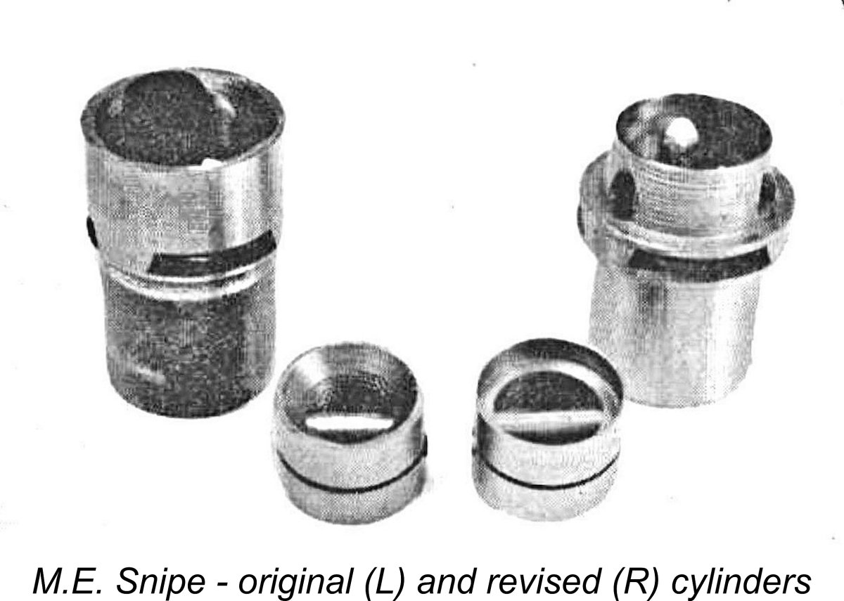
It’s readily apparent that Kendall had three primary objectives when designing the Snipe. Firstly, he wished to enhance the specific output of the engine (BHP/litre). Secondly, he felt the need to address the previously-mentioned fragility of the cast iron cylinder used in the Heron. And finally, he wanted to introduce the necessary flexibility to allow the easy conversion of the new model to R/C applications through the addition of a throttle. As of the early 1960’s, the R/C field was well on the way to dominance in the model engine market - Kendall clearly recognized this.
This revised design gave rise to a new problem. Given the continuing use of a fully floating gudgeon pin, there was every possibility that the end of the pin could foul one of the bypass flutes, with consequent bore damage. To get around this, the Snipe's rather heavy cast iron piston was grooved to accommodate a thin wire pin-retaining circlip.
One Taipan model as well as one variant of the Dunham Elfin 249 replica also used the circlip wrist-pin retainer idea - Kendall wasn’t alone in his thinking here. However, neither Gordon Burford nor Dunham repeated this feature in later models. Some designers have used a press-fitted pin, although these tend to distort the piston, requiring extra running-in and making disassembly and re-insertion uncertain. Both Thorning Bensen and the Pepperells independently came up with an innovative and unique solution: solder or braze the pin in place prior to the final lapping of the piston! The cylinder fragility issue was addressed very simply by switching the cylinder material from cast iron to steel. A cast iron and steel piston/cylinder combination had long been proven to be eminently satisfactory in service by the time in question.
Unfortunately, a significant glitch arose in connection with the original un-throttled venturi. In his search for more power, Kendall tried a venturi which, while having an internal diameter of 5.5 mm in its externally-threaded section at the base, was expanded to all of 7.5 mm at the spraybar location. It was found that while this did release significantly more power at higher speeds, it made suction, starting and needle response highly problematic. No surprise here, because reference to Maris Dislers’ Intake Choke Area calculator tells us that even with minimal suction the minimum stable operating speed of a 1.49 cc engine using a 0.125 in. (3.175 mm) diameter spraybar in conjunction with a 7.5 mm venturi diameter is 29,336 RPM! No chance ………….. Kendall evidently recognized this immediately. However, through some kind of a mix-up in the drawing office, the drawing supplied to the machine shop incorrectly showed the large-bore venturi which had been tested and found wanting. Consequently the first few batches of engines sent out featured the large-bore venturi. The error was not caught at the factory product testing stage because the M.E. testing set-up featured gravity fuel feed which masked the problem. It didn’t take long for the issue of the oversized intake venturi to become glaringly apparent. Many early customers experienced great difficulty in starting and running their new Snipes - indeed, the engine acquired an early reputation as a problematic starter. This can’t have helped the Snipe to make a successful market debut.
The manufacturers also publicised the problem quite openly, co-operating with their trade distributors KeilKraft to institute a scheme whereby owners of engines fitted with the oversized venturis could obtain correctly-sized replacements free of charge. Since the fitting of the correctly-dimensioned component completely solved the former problems, the reputation of the Snipe recovered very rapidly from what could easily have turned into a public relations disaster. Moreover, the manufacturers acquired a high level of trust among their customers. Another noteworthy innovation on the Snipe as originally released was the incorporation of a rearward bend in the fuel pickup end of the brass spraybar. This greatly facilitated the routing of the fuel line in many model installations. Apart from the changes to the intake structure, the cylinder material, the cylinder porting, the piston configuration and the spraybar, the Snipe was in essence simply a scaled-up Heron in terms of its construction. Hence there is no need for a detailed description here. Since the engine’s performance is doubtless of far greater interest, I’ll proceed directly to that subject. The M.E. Snipe on Contemporary Test Following its April 1962 introduction, the M.E. Snipe had to wait a while for the model engine testers of the day to get to grips with it. This delay was caused primarily by the previously-discussed fact that as initially released, the engine embodied a serious design flaw, namely the oversized intake venturi mentioned earlier. In fairness to the manufacturers, testing of the engine for publication was delayed until the revised venturi was available.
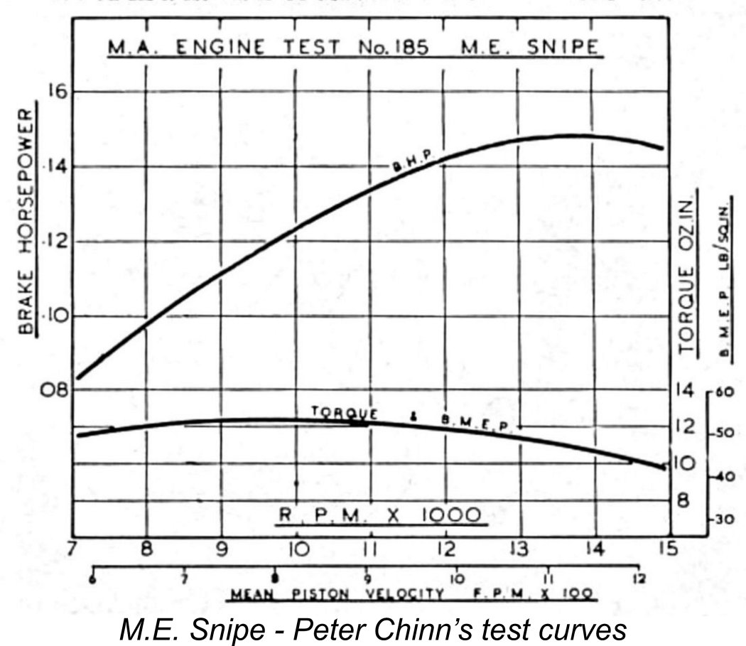
Chinn spent a good deal of his report discussing the previously-noted issue with the intake venturi bore size. He cited this as the main reason why his report had been somewhat delayed. Most informatively, he retained the oversized venturi with which his test example had been supplied, allowing him to conduct a parallel test of that component. He confirmed that the fitting of the smaller-bored venturi completely eliminated the handling problems experienced initially, also confirming that the difference in performance between the two components in the vicinity of 8,000 rpm amounted to only some 100 rpm. However, at speeds in the 11-12,000 rpm bracket, the speed differential had risen to around 5-600 rpm, while in the region of 15,000 rpm the difference had risen to 1,000 rpm. Since the power required to drive a given prop increases roughly as the cube of the speed, this represents a power increase of some 20%. After describing the engine’s main structural features, Chinn proceeded to summarize the engine’s performance characteristics. His main criticism was the fact that he found vibration to be “somewhat higher than had been anticipated”, probably due to the relatively heavy piston combined with the un-counterbalanced crankweb. Otherwise, he classified the Snipe’s starting as “good”, noting that an exhaust prime was never required - finger-choking alone invariably sufficed. Chinn praised the engine’s ability to sustain its torque development in the 8,000 - 12,000 rpm range, allowing it to swing a range of useful propeller sizes with authority. Measured peak power output was 0.148 BHP @ 13,900 rpm - a completely acceptable figure by the standards of the day for a simple sports diesel like this. Maximum BMEP was found to be 54 PSI @ 9,800 RPM - a good but not exceptional figure.
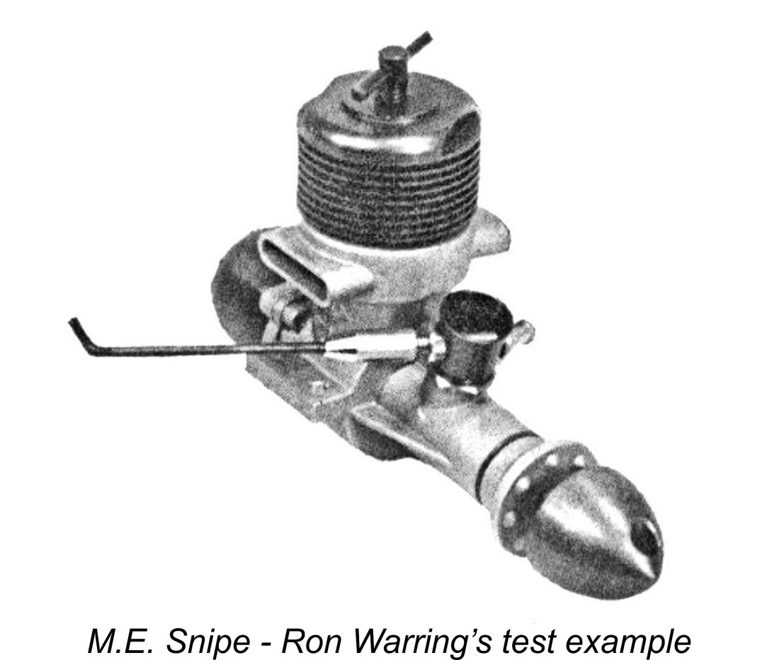
Ron Warring’s test of the Snipe appeared simultaneously in the September 1962 issue of “Aeromodeller”. Warring began by characterising the Snipe as being “essentially a sports engine, but with a very creditable performance”. He went on to describe the engine in some detail, commenting on the excellence of the fit and finish of the crankshaft in its Meehanite main bearing sleeve and noting that the same high standard applied to “every machined component”. He mentioned the initial problem with the oversized venturi bore originally fitted, but characterized the handling characteristics of the corrected version as “extremely good”.
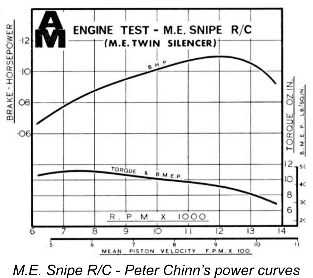
Peter Chinn wasn’t done with the Snipe at this point! In December 1965 "Model Aircraft" published its final edition, merging thereafter with “Aeromodeller” to continue jointly under the “Aeromodeller” name. Ron Warring bowed out of the engine testing field at this point, turning that responsibility over to Peter Chinn as of the January 1966 issue. As it happened, Chinn’s very Chinn’s conduct of this test coincided with the late 1965 introduction of a completely revised cylinder porting design involving three drilled upwardly-angled transfer ports along Oliver or FROG lines in place of the internal bypass/transfer flutes used previously. The piston design was also amended to reduce its weight significantly - a very positive move. For some unaccountable reason, the circlip retention of the gudgeon pin was initially retained despite the fact that with the type of porting now used this appeared to be redundant.
Apart from the re-designed piston/cylinder assembly and the addition of a throttle, the balance of the design was unchanged. In response to growing concerns over noise in relation to flying field retention, the manufacturers had also introduced a pair of matching silencers. Chinn found these to be extremely effective, characterising the engine as being “just about the quietest of all model engines of similar displacement” that he had tested up to that point.
Chinn summed up the M.E. Snipe R/C as being” not the lightest of small R/C engines, but it is robustly made, handles nicely and is undoubtedly good value at its present price of under 90s (£4.50) including silencers”. The three tests summarised above represented very positive endorsements of the M.E. Snipe by the two most widely-read British model engine testers of the day. Let’s see now how the engine stacks up in a present-day test! The M.E. Snipe Revisited All of the contemporary tests summarized above related to the original version of the M.E. Snipe with the internal flute bypass/transfer passages. Since we seem to have a pretty good handle on the performance of that variant thanks to the efforts of Chinn and Warring, I thought that more could be learned by testing an example of the later design with the “Oliver ported” cylinder. Happily I have just such an engine on hand. It’s one of the later red-anodized engines manufactured by Marown Engineering prior to the take-over by Moore Engineering (see below). It has had a fair amount of use by me in control-line service, hence being well run-in. I’m glad to say that I’ve taken care of it to the point that it still retains its tank and original needle valve. It thus remains in complete and original condition. Despite the use to which I put it, I never actually took any prop-speed readings - I just flew it! My notes simply record that it seemed to perform at a perfectly acceptable level.
The Snipe proved to be an excellent starter and a very smooth runner, with no indication of the sagging tendency reported by Peter Chinn. The only issue that I experienced initially was a certain tendency for the cooling jacket to unscrew itself. A really good tighten when hot cured this issue completely. Otherwise, the engine did very well indeed - there were no indications of the tightness problems that Maris had experienced with the Heron. There was perhaps a little more vibration than average for an engine of this displacement, but nothing to cause any problems. The reduced reciprocating weight of the revised piston/rod set doubtless contributed to this happy situation. Once running, both controls held their settings very securely while remaining easy to adjust. The needle valve proved to be commendably non-critical, while the best compression setting was very well marked. Overall, the engine was a real pleasure to test! The following data were recorded.
As can be seen, the revised design with its drilled transfer ports in place of the original internal flutes turned out to develop about the same output as that extracted by Peter Chinn from the original model. However, it did so at a considerably lower speed, implying enhanced torque development at the lower end of the speed range. My test example with the revised cylinder porting delivered a peak output of around 0.153 BHP @ 12,100 RPM. Although these findings rather fly in the face of Peter Chinn's observations in relation to his test of the Snipe R/C model with the Oliver-ported cylinder, I have to say that I'm really not that surprised. Walter Kendall was a very capable designer who must surely have tested the cylinder porting modifications and satisfied himself of their effectiveness. There's no logic at all behind the notion that he would have switched to a re-designed cylinder that under-performed by comparison with the previous model. However, the pursuit of greater torque at moderate speeds made complete sense in a sports engine context. Note that the test unit delivered 0.140 BHP or greater at all speeds between 10,200 RPM and 13,100 RPM. Some outstanding mid-range flexibility there along with a wide prop selection window! I think it likely that Chinn just got a bad drilled-port piston/cylinder combination to test and that my results are more representative of the potential of the revised cylinder design. The M.E. Range - Production History In the writing of this section of the article, I must acknowledge the help received from my two Aussie mates Maris Dislers and Gordon Beeby. Both of these valued friends trolled their respective magazine collections, which far outstrip my own, to find articles and advertisements which helped to throw light on this aspect of the story, particularly during its latter stages. Without their help, I could never have sorted out this topic from start to finish. Thanks, mates! We saw earlier that following his break with Davies-Charlton in 1959, Walter Kendall had established himself in premises located at Glen Vine on the IOM, trading as Marown Engineering. The new venture seems to have started with a relatively modest inventory of machine tools, although Kendall and his associates clearly knew how to use what they had. It appears that Kendall kept his eye on the bigger picture while producing the M.E. Heron and later the M.E. Snipe in substantial numbers. He was evidently able to build up a “war chest” of sorts to prepare the ground for a considerable expansion in the scope of his company’s activities. In late 1962 Kendall was ready to make his first move. By January 1963 he had relocated his workshops to a new location at Union Mills, still on the IOM, advertising from that location from March 1963 onwards. His new facilities were set up to maintain production of the M.E. Heron and Snipe while also enhancing his ability to expand into the aerospace industry through undertaking sub-contract work for Rolls-Royce and others. It can’t be doubted that he used his ongoing influence with Rolls-Royce to facilitate this activity.
At some point, Kendall expanded the range of his activities by moving into the petro-chemical instrumentation field, doing so through a subsidiary company called Kenmac Controls. In fact, by the late 1960’s he had evidently lost interest in continuing with the M.E. model engine range, actually going so far as to terminate production in late 1969. The last Marown advertisement that I could find appeared in the October 1968 issue of “Aeromodeller”, although an advertisement did appear in the 1969 “Aeromodeller Annual”. Maris Dislers found a dealer advertisement from the Model Shop (Guernsey) dated July 1969 in which both the Heron and Snipe were still listed. However, Marown seem to have abandoned model engine manufacture at around this time. As the 1970’s began, interest in small sports diesels like the M.E. models was very much in decline as R/C glow-plug units were taking over centre stage in the model engine market. However, the M.E. range was by no means finished yet! Kendall had terminated his own production but was naturally amenable to transferring the range to some other party having an interest in continuing. In early 1972 he found such an individual in the person of John K. Moore, who had worked with Kendall at D-C Ltd. way back in the early Barnoldswick years and may have been working for Kendall at Marown during the 1960’s.
Conveniently enough, the new company's title matched the engines’ M.E. trade-name, hence requiring no change! At some point following Marown’s divestment of the M.E. range to Moore Engineering, both of Walter Kendall’s companies (Marown Engineering and Kenmac Controls) were acquired by the Delta Corporation. The M.E. Heron was the first model to be re-introduced as a result of this move. However, a few cost-cutting measures were implemented by Moore Engineering. The most significant change was the elimination of the cast iron bushing for the crankshaft bearing - the shaft now ran in a more conventional plain bearing machined directly into the crankcase material. The red-anodized metal tanks were replaced by moulded plastic items. Peter Chinn described these changes in his previously-cited July 1972 article. In addition, the red anodizing applied to the spinner nuts and cooling jackets was dropped quite early on. The re-introduction of the M.E. Snipe took a little longer - Chinn announced this event in his LEN column for April 1973, also describing the various changes which were implemented at that time. Although the Snipe continued to feature the revised Oliver-ported cylinder and lightweight piston introduced by Marown in October 1965, the gudgeon pin retaining circlip was now omitted, as was the groove in the piston wall which formerly accommodated it. Instead, the gudgeon pin was now pressed in. The heat treatment of the shaft was amended, while the rearward bend in the fuel pickup end of the spraybar was omitted. Although the first units produced by Moore Engineering continued to feature the red-anodized components, this additional step was soon dropped, as it was with the re-introduced Heron.
At some as-yet undetermined point along the way, Moore Engineering transferred the residue of the M.E. project on some basis to a new firm called Mayglen Engineering Ltd. of Market Place in Peel, IOM, once again remaining consistent with the initials by which the range was known. It seems not unlikely that Mayglen’s involvement was confined to the assembly of engines from surplus parts manufactured by Moore Engineering. It’s evident that even this final effort left many components still unused, implying that a considerable degree of over-manufacturing had taken place. Literally sacks full of unused M.E. components have shown up in the UK from time to time. Since none of the M.E. manufacturers ever stamped serial numbers on their engines, a unit assembled from such components may be difficult or impossible to distinguish from the real thing. Caveat emptor, and don't catch auction fever! Buying an engine which retains its box is the best guarantee of originality, and even that is not absolutely fail-safe.
Given the astonishing frequency with which large batches of unused M.E. parts used to show up on the UK market, it’s entirely possible and perhaps even likely that these engines were intended to be based upon original M.E. components assembled by Dunham, with any missing bits being manufactured by Dunham as necessary. An image was included in the article supposedly showing the Dunham versions of the 1 cc M.E. Heron and 1.5 cc M.E. Snipe, together with an engine which never reached the market at any time, the M.E. Wren of clearly lesser displacement. Gordon Beeby actually found a single reference to this model in the January 1981 advertising placement by Michael's Models, which announced the forthcoming availability of the "New for 1981" M.E. Wren 0.5 cc diesel. However, this seemingly stillborn offering was never mentioned again. Despite the unavoidably poor quality of the only available scan, the image referred to by David Owen seems to prove conclusively that at least one prototype of each of these models was produced. However, there may be a wrinkle in David's attribution of the illustrated replicas to Dunham! In Part 6 of his article on "The Mills Story" which appeared in the March 1996 issue of "Model Engine World" (MEW) magazine, Mike Noakes included the following statement: "Richard Day and Richard Johnson ran Attachport Ltd. at Water Lane, Frisby on Wreake, Leicestershire......... Attachport also bought the rights and tooling from Marown Engineering for the Snipe 1.5 cc and Heron 1 cc. These came onto the market I believe in replica form during 1986. More interesting was the tooling for the A-S 55, but I am unaware of any subsequent production of this rarity. However, the M.E. reproductions don’t appear to have entered series production in quantity".
Marown Engineering was long gone as of the 1980's and the M.E. range was then in the hands of Mayglen Engineering. So if Attachport acquired the M.E. rights and tooling in the 1980's, it certainly wasn't from Marown! Moreover, I can't find any mid 1980's references to such replicas - all we have is the above 1996 comment from MEW. So I'm a little cautious regarding complete acceptance of this story ......... although it does throw considerable doubt into David Owen's identification of Dunham as the replica maker. Regardless, my thanks to Maris Dislers and Gordon Beeby for pointing out this seemingly contradictory reference. Whoever made it, it’s immediately obvious from an inspection of the image that the Wren was actually nothing more than a renamed rendition of Alan Allbon’s excellent A-S 55 diesel of late 1959! It seems possible, albeit completely unproven, that M.E. acquired the residue of the A-S 55 project after the original manufacturers Allbon-Saunders terminated model engine production in 1964, but never commenced production of that model on their own account. If anyone out there knows more about this stillborn project, please get in touch .......... Conclusion I hope that you’ve enjoyed this retrospective look at one of Britain’s less-prominent and rather under-rated model engine ranges. The M.E. diesels were excellent small sports diesels embodying a very high standard of quality along with first-class handling attributes and a perfectly adequate performance for their intended applications. They may not have embodied any ground-breaking technology or set any performance records, but they served their owners well - I know, because I’ve been a user myself! As such, they fully merit our respectful remembrance. ______________________ Article © Adrian C. Duncan, Coquitlam, British Columbia, Canada First published July 2022
|
||
 When model engine enthusiasts think about the various "consumer grade" British ranges which were on offer during the early 1960’s, famous well-established names like
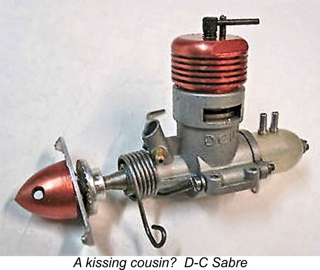
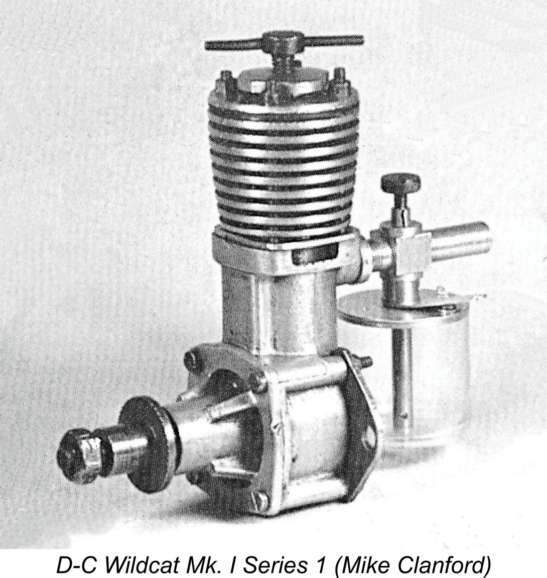 The D-C venture got its start in 1947, when former Rolls-Royce employee Hefin Davies established a workshop in the eastern Lancashire town of Barnoldswick (colloquially known as “Barlick” and its inhabitants as “Barlickers”). Davies’ original product was the very workmanlike D-C Wildcat 5.3 cc diesel which appeared in three successive variants and was deservedly very well received.
 legally defined as a self-governing British Crown Dependency. Consequently, IOM residents are British citizens who travel on British passports.
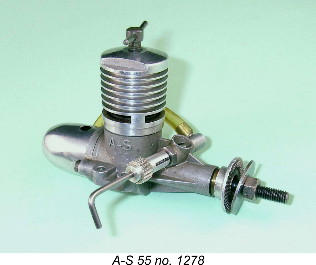
 Whatever the reason(s), it appears that by 1959 Kendall had reached the end of his tether. It was in that year that he finally severed his connection with D-C Ltd., following Alan Allbon’s lead by taking steps to establish himself independently in premises located at Glen Vine on the IOM, trading as Marown Engineering (M.E.). The initial offering from this company appeared in June 1960 in the shape of the M.E. Heron 1 cc diesel.
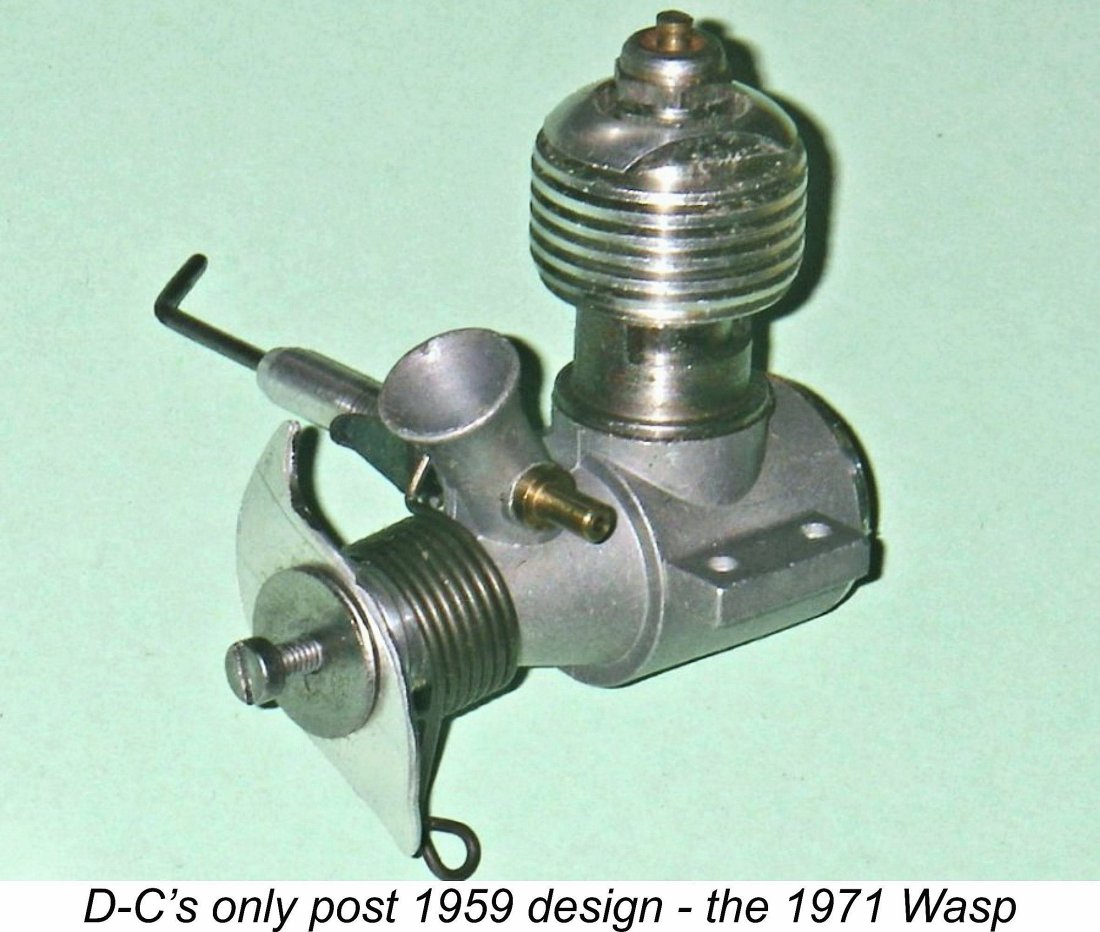
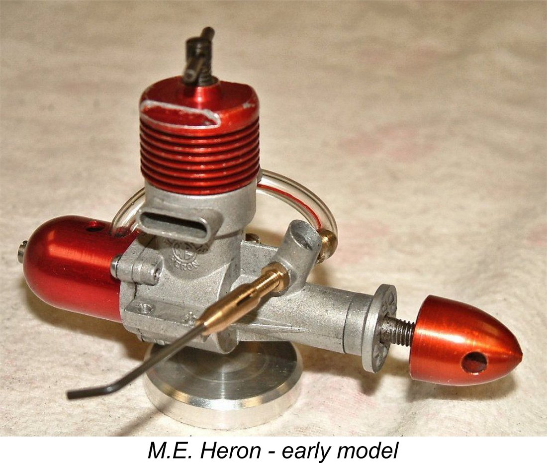
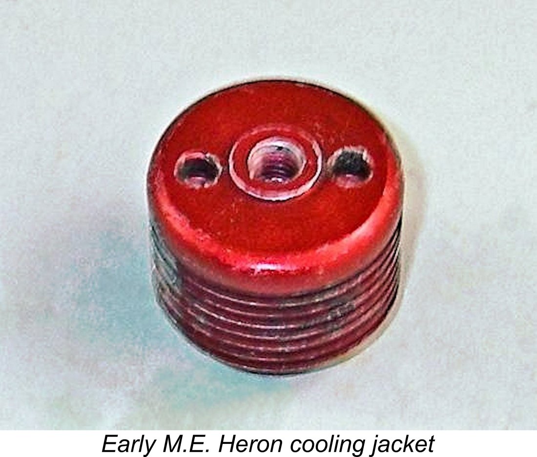 Starting at the top, the cooling jackets on the Marown engines were anodized red. They featured an externally-threaded lower spigot which engaged with an internally-threaded portion of the upper crankcase above the twin exhaust stacks. This system precisely mirrored that used in the earlier D-C designs by Alan Allbon. The relatively rare original jackets were provided with two blind holes in the top for a pin-spanner (supplied with the engines, according to the early advertisements). The later and more familiar versions sported flats machined on the sides of the jacket’s top to accommodate a conventional spanner, presumably as an economy measure. The compression screw thread was 2 BA.
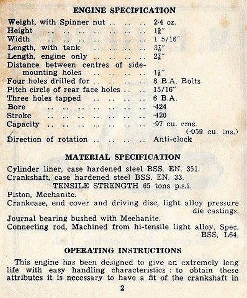 The cylinder liner was originally machined from Meehanite cast iron. While an easy material to work, this choice of material does make the cylinder rather delicate and hence somewhat prone to cracking under stress. Indeed, examples with cracked cylinders are not infrequently encountered - Ron Chernich’s marine example had suffered in this way. It appears that the manufacturer quickly became aware of this problem, since the material was changed quite early on to the more conventional case-hardened steel. The material specification in the instruction sheet was amended to reflect this change, as seen in the attachment at the right. The next model to appear, the 1.5 cc Snipe of 1962 (see below), featured a steel cylinder liner from the outset.
 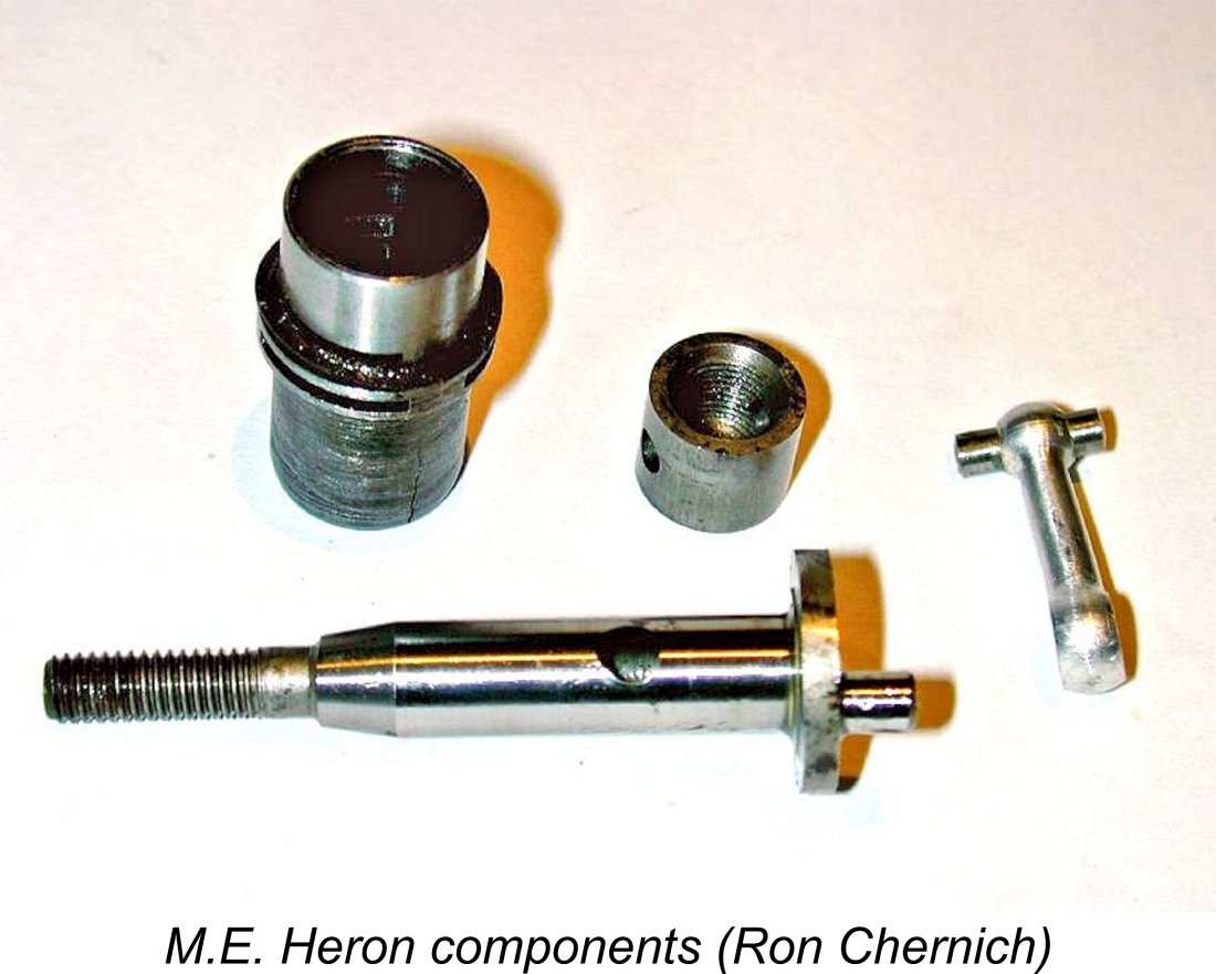 Turning now to the working components, the Meehanite piston was a little unusual in that it was flat topped and rather thick-walled over its full length, making it somewhat heavier than might have been ideal - high reciprocating weight is no friend to performance! It was internally threaded, presumably for mounting on a mandrel while grinding/honing. The Meehanite contra-piston had a similar internal thread.
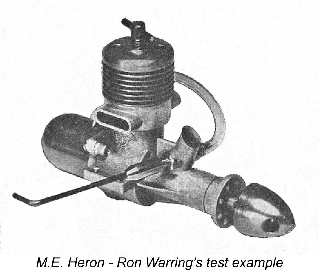 First out of the starting gate on this occasion was Ron Warring of “Aeromodeller” magazine, whose
 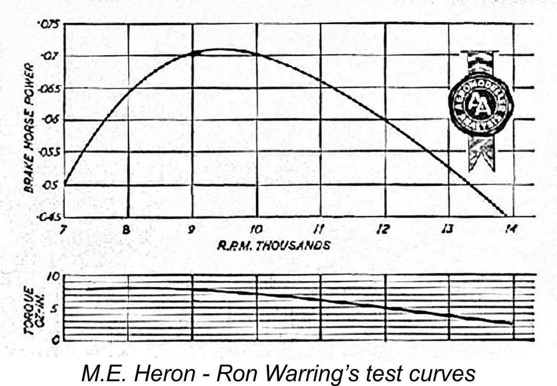 In performance terms, Warring qualified his findings by reminding his readers that the Heron was specifically designed as a docile sports engine, hence not reasonably being expected to deliver high power at higher speeds. He measured a peak output of 0.072 BHP @ 9,500 RPM both being somewhat sub-average figures. Maximum torque was measured as 8 ounce-inches at 8,500 RPM. Clearly these figures defined the Heron as a moderate-speed sports engine whose strong suit would be turning a prop of useful size at a good speed for sport flying applications. Warring considered that an 8x4 prop would suit the engine well in a free flight application, while a 6x6 should work nicely in control line service.
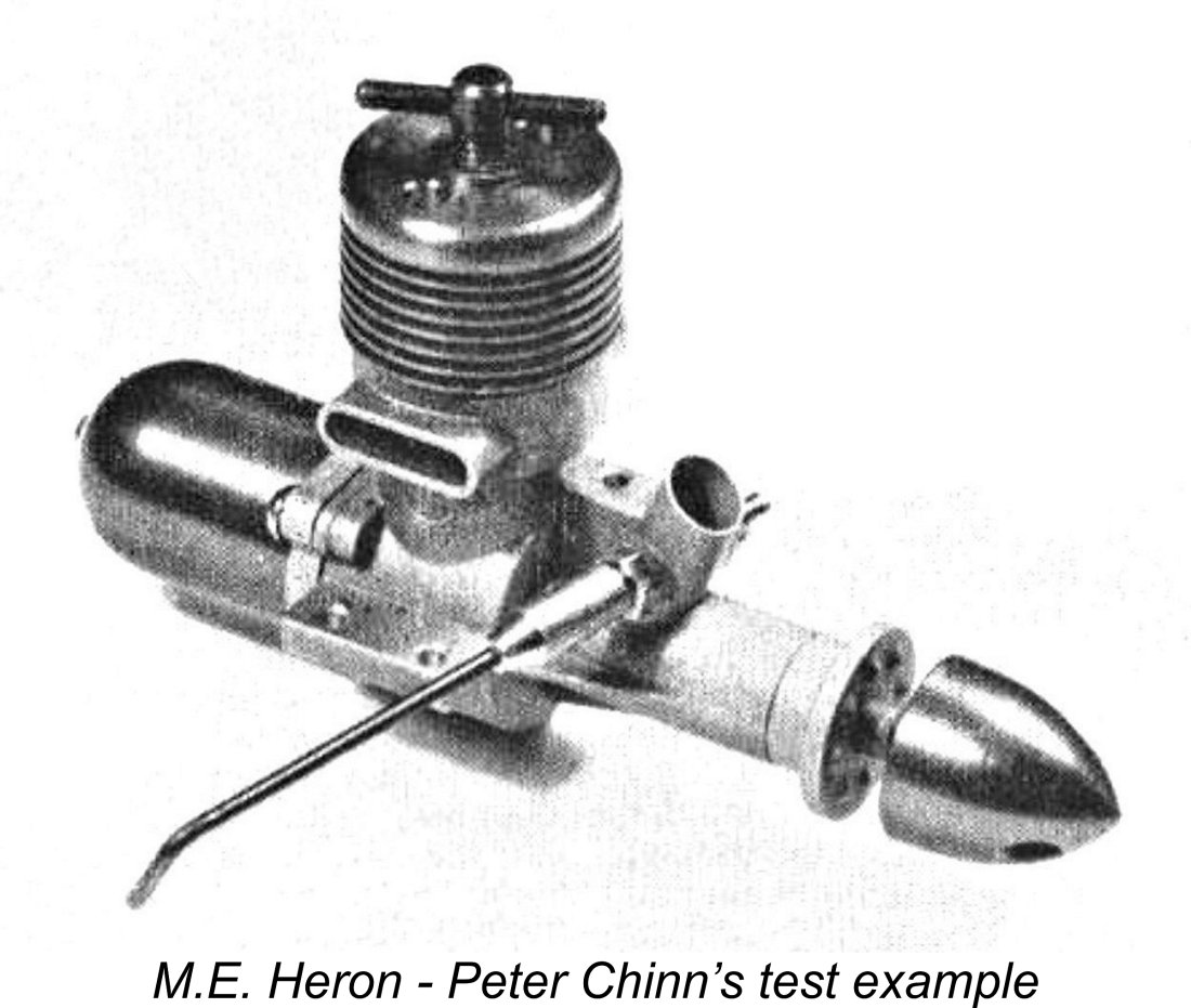 Peter Chinn of “Model Aircraft” magazine was a little slower off the mark than Warring - his
 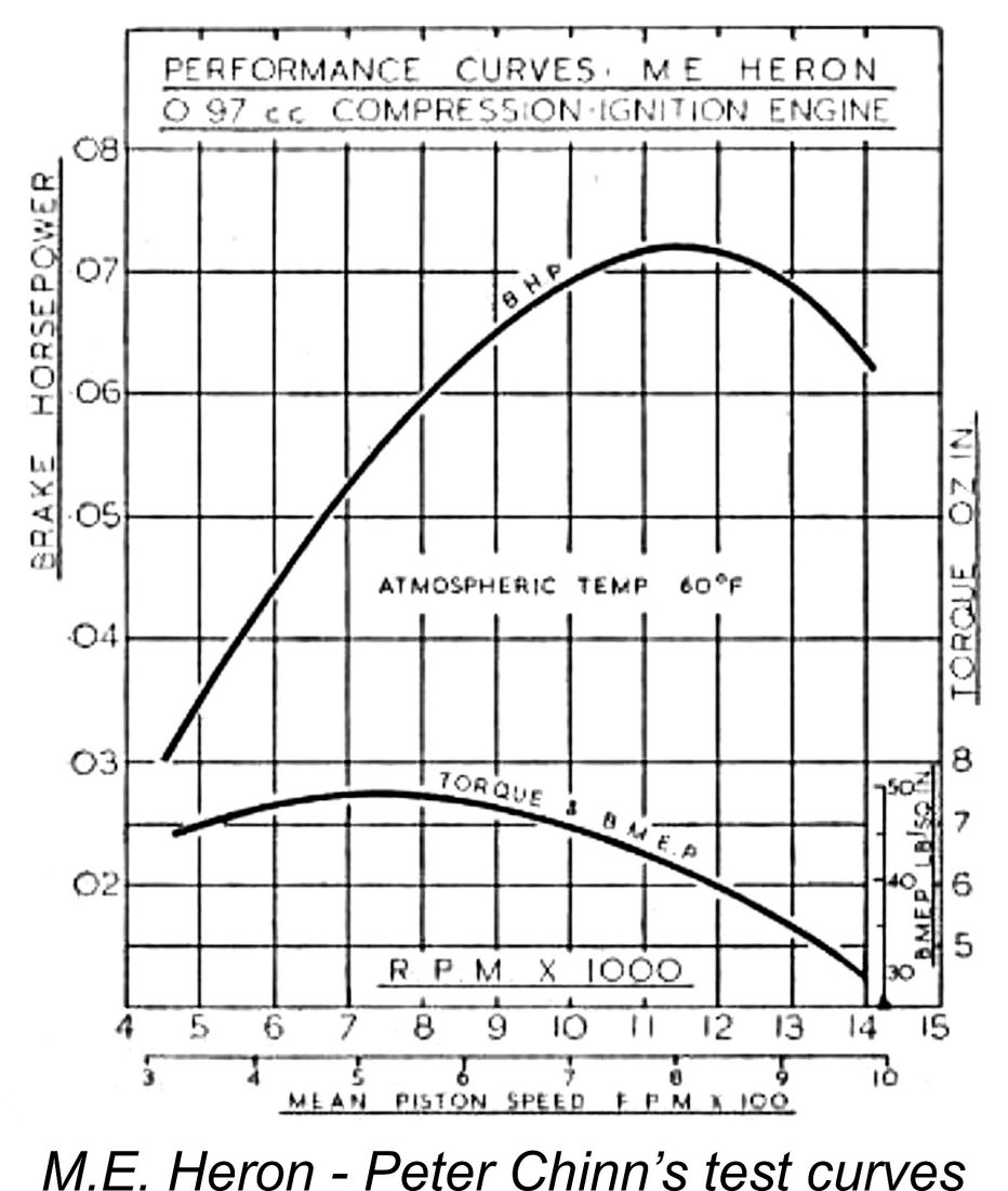 Chinn described the engine in some detail, commenting in particular on the use of a Meehanite bushing for the crankshaft bearing as well as the reasons for that feature being applied. He noted that he had received some reports to the effect that starting was not as easy as it might have been, presumably due to tightness in the main bearing. However, his test example exhibited no such problems - Chinn specifically noted that "there was definitely no excessive tightness in the main bearing".
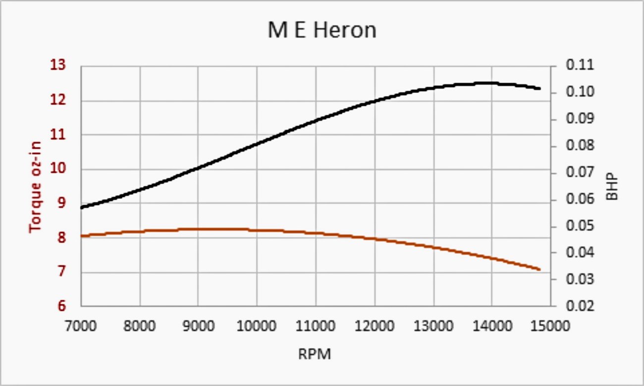
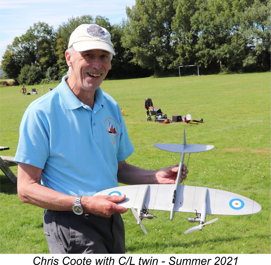 The impressions of another user of any given engine are always of great value when writing about that particular model. Upon learning that I was planning to write this article, my valued friend and colleague Chris Coote of Bristol, England was kind enough to share his experiences with the M.E. Heron. It turns out that an M.E. Heron purchased in late 1960 was Chris's first new engine. He had saved long and hard to accumulate the purchase price, doing so in secret because his father had decreed that he was not to have an engine until he had successfully built and flown a built-up rubber-powered model!
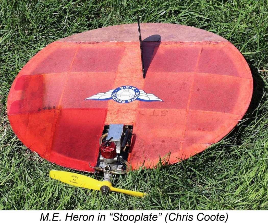
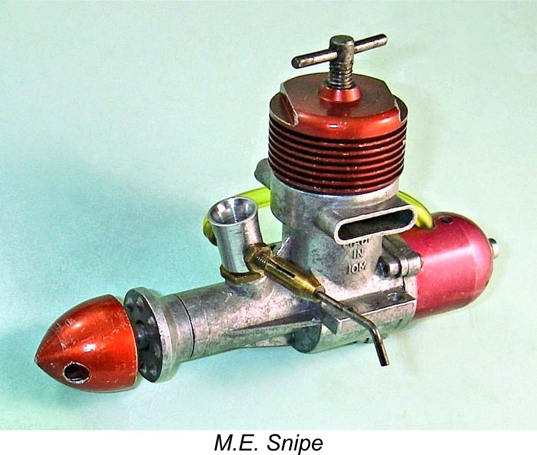 It was only to be expected that the success of the M.E. Heron would encourage the development of other models in the range. It’s actually a little surprising that this took as long as it did. The next model to appear in the M.E. range was the Snipe diesel of 1.49 cc displacement. This unit took its place alongside the Heron in April of 1962, almost two years after the appearance of its smaller relative.
 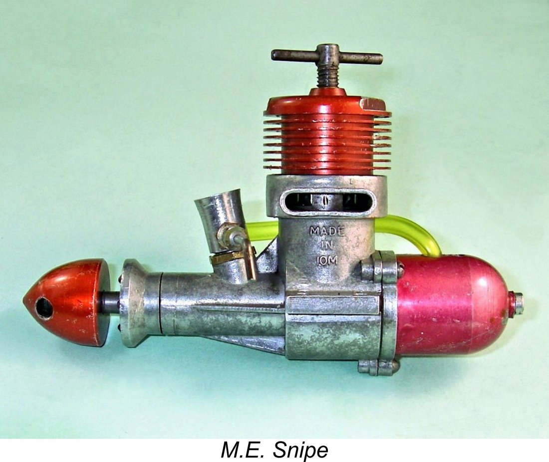 Unlike the parallel models on offer from A-M and D-C Ltd., both bore and stroke were increased from the smaller 1 cc design. Bore and stroke of the Snipe were 0.505 in. (12.83 mm) and 0.455 in. (11.56 mm) for a calculated displacement of 1.494 cc (0.0911 cuin.). The engine weighed in at 108 gm (3.8 ounces) complete with tank - a fair bit of weight for a simple plain-bearing 1.5 cc sports diesel. Present-day checks confirm these figures.
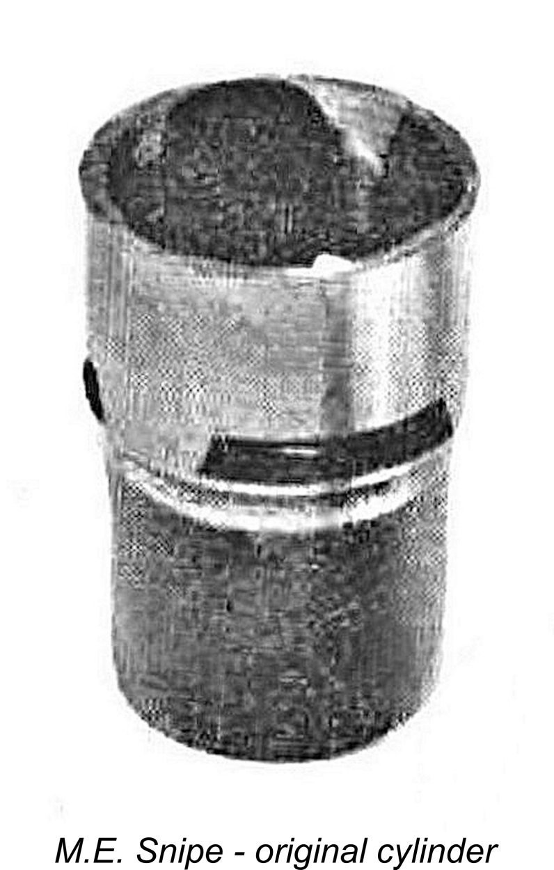 To address the first of these issues, the cylinder porting of the Snipe was radically different from that of the Heron. The new model utilized three quite large internally-formed bypass/transfer flutes along the lines of those used by
 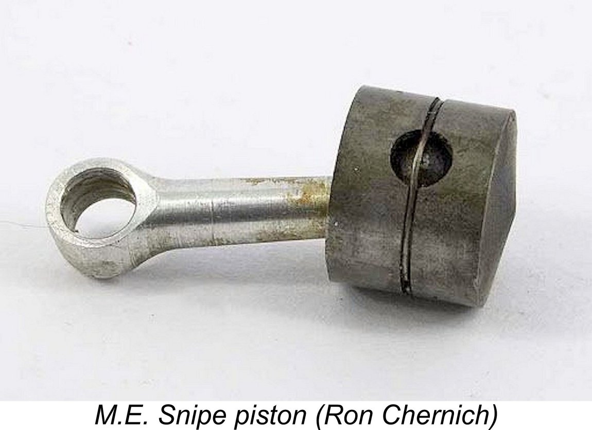 When discussing this feature with the late Ron Chernich, the late David Owen convinced Ron that this is a bad idea on engines such as the Snipe in which the transfer ports overlap the exhaust. The reason is that as the piston descends, the circlip groove will briefly connect transfer and exhaust ports well before the exhaust opens. During this period, the crankcase becomes open to the atmosphere, allowing the possibility that the higher-than-atmospheric crankcase pressure will give rise to venting of some of the fresh charge of fuel mixture via the exhaust. The duration of any such leakage will be small, and obviously such engines do run, but it's a little surprising to find this feature being introduced by a designer who had made such a big thing about retaining crankcase compression through closely-fitting crankshaft bearings.
 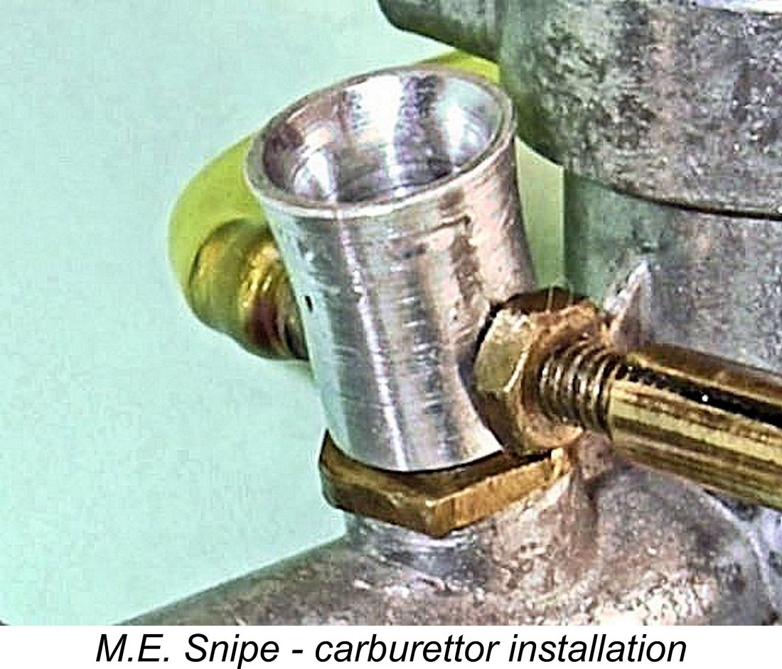 The third design objective, the introduction of structural flexibility to allow easy conversion to R/C use, was achieved through the replacement of the Heron’s integrally-cast full-length intake with a stub into which a separate intake was threaded, being secured by a brass lock-nut. This allowed the easy installation of either a conventional venturi or a custom-made throttle. An added benefit was that the needle valve could be aligned in any desired orientation.
 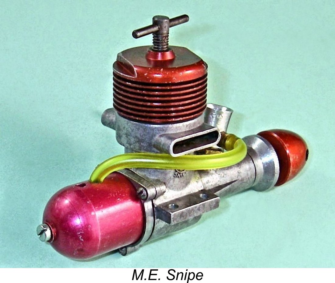 To their credit, the manufacturers moved quickly and responsibly to address this issue, as indeed they had to in order to protect their reputation. They switched production to a venturi having an internal diameter at the spraybar of only 5.5 mm. Maris Dislers’
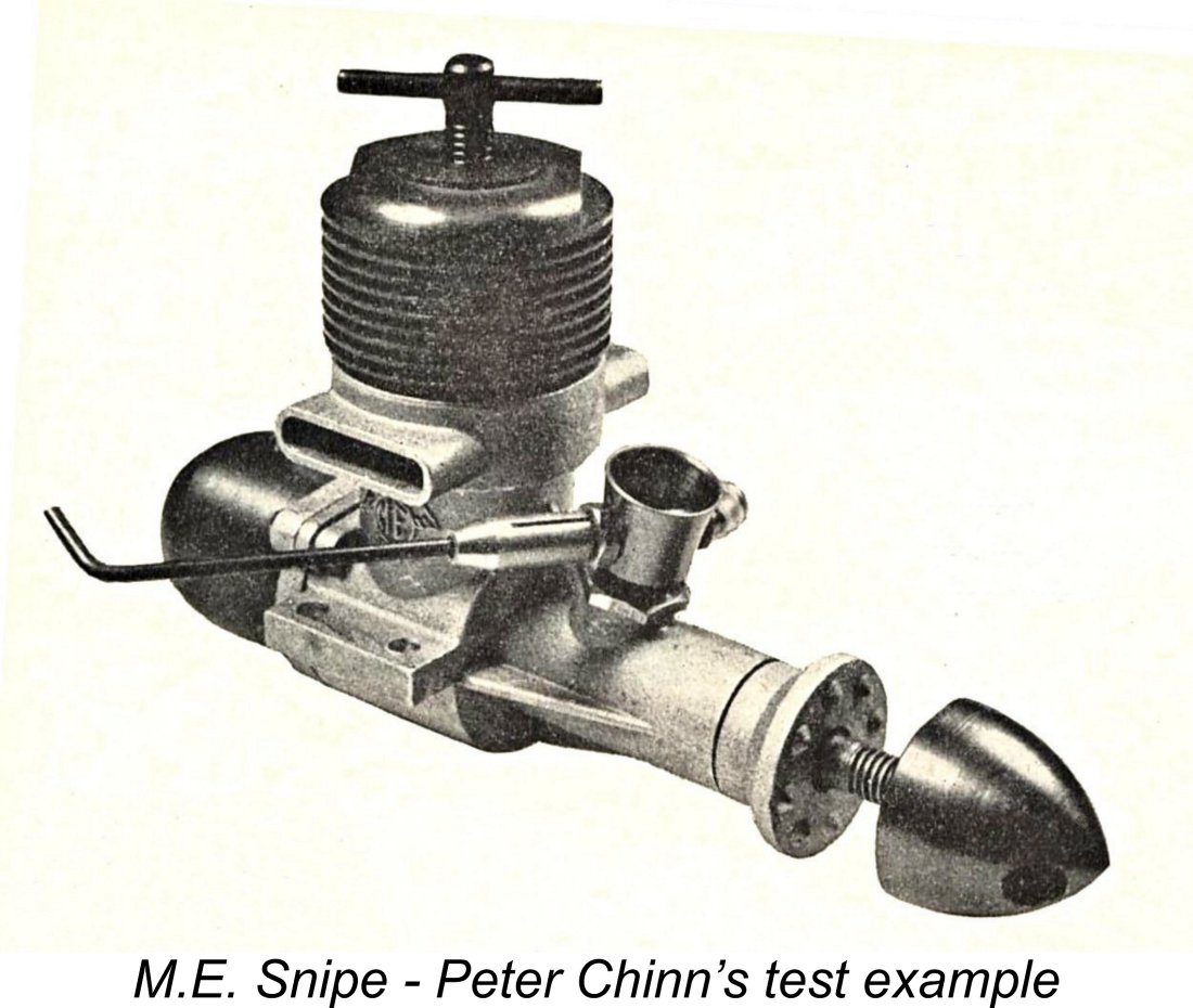
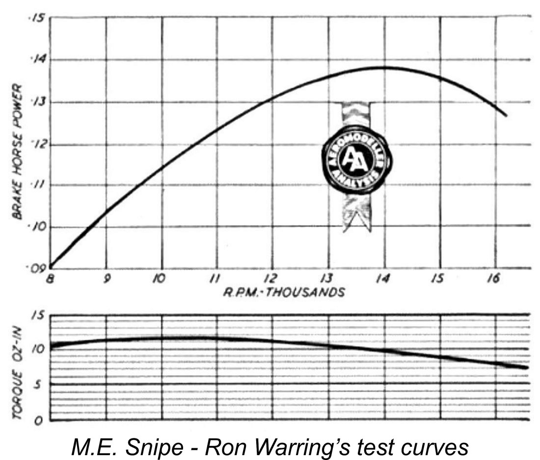 Warring reported a peak output of 0.138 BHP @ 14,000 rpm using the revised small-bore venturi - not greatly different from Chinn’s findings. He summed up the Snipe as being “about the best made sports diesel available in its size, with a snappy performance and excellent handling qualities”. He predicted that it would prove to be “a real winner in its class”, representing “wonderful value for money”.
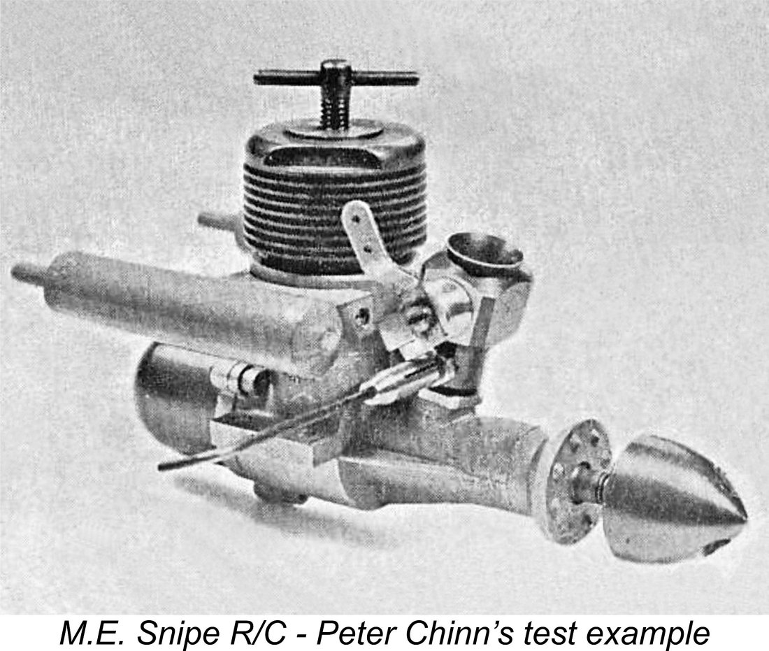
 Chinn’s test engine was fitted as received with the earlier type of piston and cylinder, but the manufacturers sent him a matched combination of the revised components to try. Accordingly, after completing his test of the engine as originally supplied, Chinn switched to the new cylinder assembly and re-tested the engine. It quickly became apparent that the re-fitted Snipe was “unlikely to reach the level of performance achieved with the original assembly”. He found that the engine ran less evenly and suffered from a more pronounced power loss upon warming up. On this basis, his report focused strictly on the performance realized with the original piston/cylinder combination.
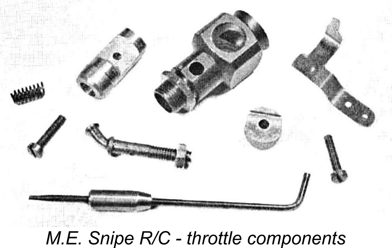
 I elected to begin this test with an APC 9x4 prop fitted. I estimated that this would probably be the heaviest load required to establish the peak - a very accurate estimate as it turned out! The fuel was a standard 35/40/25 ether/kerosene/castor oil blend to which I added 1½
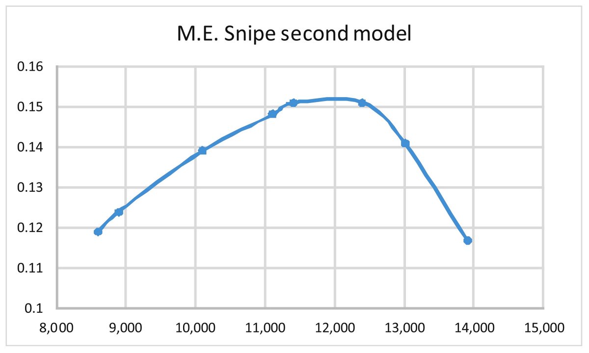
 The manufacture of the M.E. engines continued throughout this period. July 1963 saw the introduction of the Snipe R/C along with the twinned silencers for both the Heron and the Snipe. Marine versions of both models were also on offer. Although Kendall was now doubtless increasingly preoccupied with other work, development efforts were not abandoned, resulting in the October 1965 introduction of the revised Snipe cylinder with its “Oliver porting” and accompanying lighter piston.
 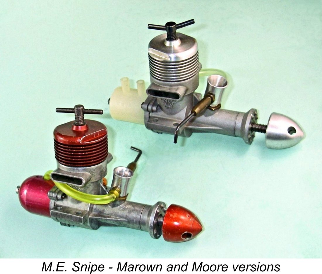 Moore and a presumably related individual named H. M. Moore took over the M.E. range in early 1972, manufacturing the engines under the name of their own Moore Engineering company from premises at Stanley Mount in Peel, IOM. It's important to note at this point that this firm had absolutely no connection with Peter A. Moore, the producer of the Embee engines. That particular erroneous connection was unfortunately published by my late good mate Ron Chernich in his
 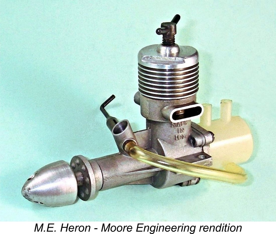 Moore Engineering reached agreement with Ripmax to act as their distributors. All subsequent advertising was placed by Ripmax, with no mention of the actual manufacturers. The M.E. engines continued to be offered throughout much of the 1970’s, with quality being well maintained. However, by the latter part of that decade demand must have fallen to very modest levels - probably insufficient to justify continued production. The final Ripmax advertisement for the M.E. range that Gordon Beeby could find was their placement of September 1980.
 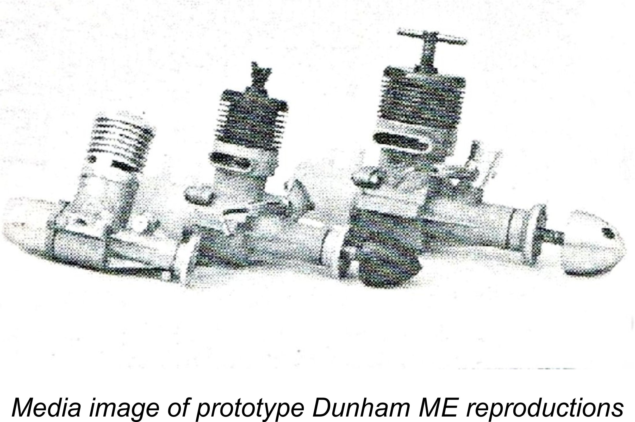 There’s an interesting postcript to this story! The late David Owen made reference to an un-dated article which appeared in the English modelling press to the effect that towards the end of their active involvement with model engines in 1988,
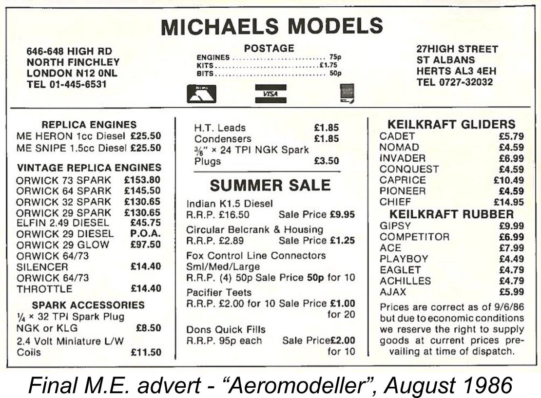
| |