
|
|
Tyneside Twins - the M.S. Diesels
A very brief but much appreciated article about the M.S. engines may be found on the late Ron Chernich's now-frozen "Model Engine News" (MEN) website. This article was written some years ago by my good friend Ken Croft, who made a superb replica of the M.S. 1.24 cc model, to be discussed below in its place. I'd also like to acknowledge my indebtedness to my Aussie mate Maris Dislers for his invaluable assistance in ferreting out a number of key advertisements which did much to establish the timelines associated with these engines. My possession of fine original examples of both M.S. models has put me in a position to greatly expand upon Ken’s earlier work, hence the motivation for the present article. In particular, I'm able to present the first-ever published bench tests of both units. During the early post-WW2 years when the M.S. engines made their all-too-brief appearance, the hands-on craft-based aeromodelling hobby was on a roll, presenting a very sharp contrast to the bought-in-a-box hands-off activity which model airplane flying has now become to a very large extent. The numerous participants in those days were aeromodellers as opposed to merely being model fliers. The part played by the Allied air forces in winning the recently-concluded war had contributed greatly to this situation by creating a high level of air-mindedness among British residents, who were naturally keen to get back to peace-time pursuits after 51/2 years of unrelenting conflict. Aeromodelling stood high on the list of potential hobbies. To fully appreciate the M.S. story, it’s helpful to place the engines in the context of their times. I’ll tackle that task first by setting the scene………….. Background
This was particularly true among the many young enthusiasts who then presaged a very healthy long-term future for the hobby. I was one of them, and I'm still here! It was also a time during which aeromodelling technology was advancing rapidly in many areas. Model engine development was very much at the forefront of these advances. It was an exciting time to be an aeromodeller! I feel immensely fortunate to have experienced it at first hand - the young people of today will never know what they missed. When I was growing up in Yorkshire, England during the Fifties and early to mid Sixties, almost all of my male contemporaries were actively involved with some form of modelling activity. No Internet, iPads, Smart Phones, X-Boxes, computer games, Dungeons and Dragons, Transformers and social media to divert us back then – indeed, many of us (including myself prior to 1962) didn’t even have a television in the house at that time! This being the case, we had to find ways of filling our time through our own efforts, a challenge which we met with energy and enthusiasm along with a strong sense of community. Modelling in all of its various forms was an obvious and widely-embraced means of filling one’s free time constructively. Many British secondary schools (including my own) had very active aeromodellers' clubs whose members got to fly on the school playing fields after school hours (try that today!) and also had access to the school wood-work and metal-work shops (yes, schools back then had those facilities, complete with machine tools!). Models incorporating “real” engines were particularly attractive. Although disposable cash was in relatively short supply for many British modellers during the early post-WW2 years, this was offset by the fact that there were a lot of such individuals who were happy to save up and pay for such modelling goods as they could afford and then put in the time and effort required to build and fly models using those goods. They accepted and indeed embraced the concept of working for their hobbies – today’s “instant gratification” mindset had yet to become imprinted. A few shillings would buy you some balsa wood, glue and dope, using which a flying model could be constructed with some thought and effort. One went onwards and upwards from there ............. This added up to a generally positive economic environment within which the various model retailers found themselves operating back in the 1940’s, ‘50’s and into the ‘60’s. During this era, hobby shops which focused very much upon kits, scratch-build supplies/materials, engines, fuel and related accessories were almost ubiquitous features of most communities of any size and were well supported by sizeable local aeromodelling and boat modelling communities. A far cry from today, when the relatively small number of community-based retail hobby shops that do remain on deck are forced more and more into the ARF and toy market sectors in order to survive.
The health of the model trade was such that a long-established major local toy shop, Redgates, reversed the present-day trend by setting up a busy and comprehensively-stocked hobby supply department alongside its toy ranges, as did London’s famous Gamages department store and the Woodwards chain in Western Canada where I've lived since 1966. All of these businesses and offshoots were able to sustain themselves very comfortably on the basis of ongoing custom from the very numerous “hands-on” craft-based modelling brigade, of which I was an active member.
This situation inevitably encouraged the various competing hobby shops to remain constantly on the lookout for some means of increasing their visibility in the marketplace, thus potentially giving themselves a market share edge. As time went by, an increasing number of them engaged in the mail-order business through a national advertising campaign in the modelling media of the day, while some even presaged today’s credit-based economy by offering model goods on the “hire purchase” plan. The generally positive market environment in which the early post-war hobby shops were operating was such that a number of them were able to go even further by introducing their own “house brand” product lines. Some retail businesses generated sufficient What is less well remembered today is that perhaps the very first model shop to enter the kit manufacturing business was none other than our main subject here, the Model Shop of Newcastle-upon-Tyne. They did so during the mid 1930's with their "Keelbild" range of kits, which were quite widely promoted in the modelling media of the day. The early post-war years saw a dramatic increase in the popularity of power modelling in Britain. Model engines were in short supply at this time and such engines as were available were eagerly sought after by the aeromodelling community despite their relatively high prices in the context of the early post-WW2 British economy. It should therefore come as no surprise to learn that a number of hobby shops of that era looked to draw attention to themselves by introducing their own “house brand” model aero engines. Of course, examples of “house brand” model engines being promoted by hobby shops as opposed to manufacturers are plentiful beyond the shores of Great Britain. In American, we can think of America’s Hobby Center (AHC) with their G.H.Q. and (later) Thor, Genie and Buzz models; Gotham Hobby with their infamous Deezil; and Cliff Fox’s Fox Specialities hobby shop in Oakland with the rather unsuccessful Baab-Fox .604 racing engine. France can show the famous Paris shop La Source des Inventions which marketed the R.E.A. engines as their own house brand. In Italy, Aviomodelli of Cremona promoted both the Folgore and OSAM models, the latter eventually developing independently into the Super Tigre range. There are many other examples. However, Britain must surely take first place when it comes to “house brand” model engines being promoted by individual hobby shops. The list is a long one - the Dyne, Ace, M.E.C., Milford, Comet, Clansman, B.M.P., Drome and Weston engines all had their genesis as hobby shop house brands, and there were others. Among those others were the M.S. diesels (not MS diesels with no periods, as so often incorrectly rendered) which form the main subject of this article. From this point onwards, I’ll focus solely upon those models. The M.S. Diesels - Inception and Marketing
Charlie Lutman’s daughter-in-law Pat took over the reins in the 1960’s, and his grandson, another Charles Lutman, also took a turn at the helm - the third generation of the Lutman family to do so. In later years, the business was relocated to Blenheim Street, near the intersection with Westgate Road. As time went on, the model product content was greatly diminished and the toy content increased (an inescapable requirement for economic survival in a changing marketplace). Even this was not enough, forcing the final closure of the business in 2005 after 81 years. End of an era ................... Returning to the early post-WW2 period, Charlie Lutman was by no means content to engage in the model trade strictly as a retailer from his then-current location at Ridley Place. We saw previously that during the mid 1930's, while still at Barras Bridge, he had entered the balsa wood flying model kit business with his "Keelbild" range. Now wishing to expand his activities into other manufacturing sectors, he established a separate manufacturing facility on the Team Valley Trading Estate in nearby Gateshead. This pioneering multi-user industrial development had been established as a government initiative in the late 1930’s.
It must have been in early 1947 that Lutman conceived the idea of producing his own house-brand model engines. He was presumably encouraged to do so by the mid 1946 appearance and speedy adoption of the commercial model diesel by the British aeromodelling community. He evidently began by focusing upon the 2.5 cc unit which was the first M.S. model engine to appear. This engine is often referred to as the M.S. 2.4 cc diesel, since that figure more closely reflects its actual displacement (see below). However, the manufacturer invariably referred to it as the M.S. 2.5 cc diesel in his advertising. In deference to the manufacturer’s own designation, I will do likewise. After all, no-one refers to the A-M 25 as the A-M 235, which would reflect its actual displacement ............... The introductory advertisement for the M.S. 2.5 cc diesel appeared in the September 1947 issue of “Aeromodeller”. This advertisement is reproduced above. It confirms that the design and tooling for the larger 2.5 cc model must have been completed by July 1947 (allowing for Editorial lead Even by the standards of the day, when engine prices tended to be a little on the high side, this was quite a chunk of change. At this point in time, a British resident earning £8 a week before taxes would have been considered well off. Imagine paying a week's-worth of your present-day income for a plain-Jane 2.5 cc sports diesel .........the wife might have something to say about that! The same advertisement was repeated through to December 1947. However, by January 1948 the advertisement no longer included the restriction of immediate availability to personal shoppers only. This gives the impression that sales of the engine had been less brisk than hoped for. Indeed as matters turned out, the January 1948 advertisement was the final placement to mention the M.S. 2.5 cc diesel. It thus appears that the engine had a very short marketplace life of only some 5 months at most. It’s unclear how many examples were actually made during that period. The only two serial numbers of my present acquaintance are number 62 which appears on my own example and Graham Podd's engine number 73. All that can be said with some confidence is that the number produced cannot have been large - examples of the M.S. 2.5 are rarer today than a mixture of hens teeth and rocking horse droppings! It seems highly doubtful that total production reached three figures. In all probability, only one or perhaps two small batches were ever manufactured. This did not prevent the engine from being included in D. J. Laidlaw-Dickson's article entitled "British Commercial Diesel Engines" which appeared in the March/April 1948 issue of "Model Mechanic" magazine. This article must have been compiled at a time when both the 2.5 cc model and its later 1.24 cc companion (see below) were concurrently available, since both models were included in the article. Potential problems with both designs were cited, of which more below at the appropriate points in the present article. As far as I can tell, the final media appearance of the M.S. marque came in the 1949 revised edition of Col. C. E. Bowden's book "Diesel Model Engines" - the first edition of that book had appeared in the latter part of 1947 more or less concurrently with the initial appearance of the M.S. 2.5 cc offering, which was naturally not covered. By contrast, Bowden's 1949 revised edition came out long after all M.S. engine production had ceased. The 2.5 cc model was not covered in Bowden's 1949 comments, which focused entirely upon the 1.24 cc unit. Bowden stated that he had tried one of these engines and found it to be "a good starter and reliable runner". He commented favourably upon the engine's compactness. Now let’s take a look at the main design features of the first M.S. model to appear - the very unusual and extremely rare M.S. 2.5 cc unit. The M.S. 2.5 cc Diesel - Description
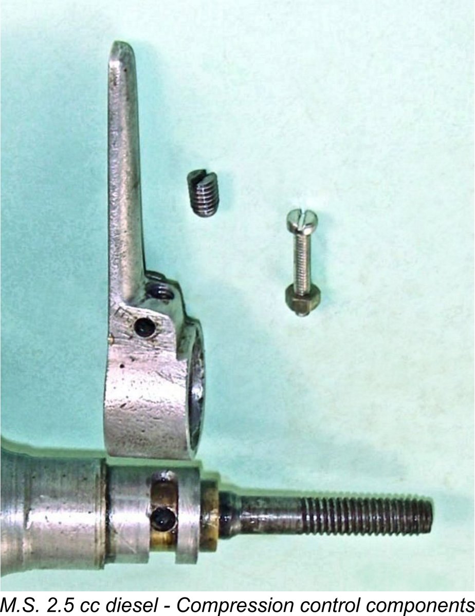
However, that all changed when Miles Patience put me in touch with Graham Podd following the original publication of this article. Graham was in possession of a photograph by John Towell of the components of a fine example of the M.S. 2.5 cc diesel which was then owned by John. Graham was unable to share that example's serial number with me, but nevertheless the internal structural details revealed by that image required me to clarify my original description to a very significant extent. My sincere thanks to both John and Graham! John's image of his engine in its dismantled state is reproduced below at the right. At a quick first glance, one might take the M.S. 2.5 cc diesel to be an essentially conventional long-stroke fixed compression sideport diesel of its era. However, it quickly proves on closer examination to incorporate a For reasons which now escape me given their consistent use of metric displacements, British model engines of this period were almost invariably designed with bore and stroke measurements which were expressed in fractions of an inch as opposed to decimal figures. As near as I can determine by repeated measurements carefully taken through the exhaust, the 2.5 cc M.S. diesel has nominal bore and stroke dimensions of ½ in.(0.500 in. - 12.70 mm) and ¾ in. (0.750 in. - 19.05 mm) respectively for an actual displacement of 2.41 cc (0.147 cuin.) - near enough to the advertised figure. The stroke/bore ratio of 1.5:1 is among the highest yet documented for a model diesel of this era - only the Airstar 2.15 cc model and the Foursome and Kalper engines exceeded this figure in my experience.
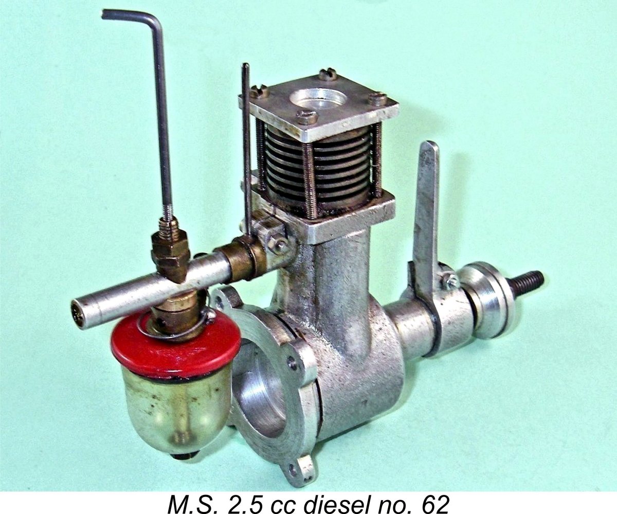
Despite repeated careful attempts at measurement, I cannot even come close to reconciling Warring’s figures with those from my example of the engine. Even by external eyeball, the relative bore and stroke are clearly far more divergent than Warring’s figures would suggest. Check out the view at the left as well as the component view reproduced above....... One actually gets the impression that Warring never found an opportunity to measure or even examine an example of the engine at first hand. This impression is strongly supported by the fact that the M.S. diesels were not included in Warring’s separate table in which structural details of British diesels were recorded - evidently he did not have access to such data. This is by no means the only example of such inconsistencies in Warring’s tables - I have encountered numerous other examples of such issues during my research for previous articles. Warring's book is a very useful reference, but its technical data cannot necessarily be taken as gospel .............. The previously-reproduced M.S. advertisement of December 1947 cited a claimed weight of 5.75 ounces (163 gm) for the 2.5 cc model. Warring’s Appendix II quotes a weight of 5.50 ounces (156 gm). Giving the deciding vote to the engine itself, my complete and original example tips the scales at 6.52 ounces (185 gm) as illustrated. I have no explanation for the obvious discrepancies.
The component view reproduced earlier confirms that the underside of the cylinder head is provided with a transverse slot to accommodate the upstanding baffle which is a feature of the piston crown. This is facilitated by the fact that this design does not include a contra-piston for compression adjustment. The head is secured with four long machine screws (or studs in some cases such as that owned by John Towell) which extend down past the outside diameter of the cylinder cooling fins to engage with tapped holes at the corners of a matching square flange at the top of the crankcase casting. Those fasteners thus secure the cylinder itself as well as the head. The disadvantage of this system is the fact that the relatively high installation stresses required to ensure a good head seal are necessarily transmitted down through the entire working length of the cylinder bore. The potential for bore distortion is obvious. The early FROG engines suffered from the same design defect. It was largely for this reason that I was unwilling to disturb what appeared to be a well-settled structure - the chances of re-establishing precisely the same bore configuration upon reassembly are slim. Moreover, the head and cylinder base appear to be very effectively sealed with some kind of gasket compound. Any disturbance would destroy those seals. The cylinder is turned from close-grained cast iron, the cooling fins being formed integrally. The exhaust porting in my example consists of a pair of closely-spaced round holes of generous size which are separated by a narrow pillar of material to promote bore and piston stability. The example which appears in John Towell's previously-reproduced component image appears to have a single exhaust opening of "race-track" configuration - evidently several different arrangements were tried. Either way, the exhaust port discharges into a rectangular stack cast integrally with the main casting. The latter component is produced by sand-casting. The transfer ports are similarly formed as a pair of adjacent drilled holes. They overlap the exhaust almost completely. They are supplied with mixture through a bypass passage cast integrally with the main crankcase. The piston is also made from cast iron. Later experience has shown that cast iron on cast iron is not the best material combination for long wearing properties - the makers of the A-M diesels were to learn this the hard way during the 1950’s. However, the combination was fairly widely used at the time in question. If the engine is kept scrupulously clean and supplied with an "oily" fuel, the wear issue should be maneagable with a low-speed engine of this type. Certainly, my example has clearly done a fair bit of running but retains a near-perfect piston/cylinder fit. The piston crown is provided with a low upstanding baffle on the transfer side. A series of oil grooves are cut at intervals into the piston's unusually long skirt. The piston drives the crankshaft through a drop-forged bronze conrod. The crankshaft itself is a one-piece component machined from silver steel and having a heavily counterbalanced crankweb. Main journal diameter is 0.250 in. (6.35 mm).
In this configuration, the main bearing is equipped with a bronze bushing inserted into the crankcase's main bearing housing. This serves as the bearing shell which supports the main crankshaft journal. So far, so familiar, but with this system the bushing is internally bored eccentrically (off centre) rather than centrally as in the usual case. Conventional bushings of this type are usually a very tight fit in the surrounding cast material to prevent rotation during operation. However, in the case of an engine such as this one the bushing is a smooth push fit in the centrally-bored main bearing casting, leaving it well supported but free to rotate within the casting. Since I'm unwilling to dismantle my M.S. 2.5 for internal photographic purposes, the attached images of the similarly-designed Thermite 34 from America will have to suffice.
In the case of the M.S 2.5, the 0.375 in. external diameter main bearing bushing is internally bored at 0.250 in. diameter off-center by 0.0125 in. This means that the crankshaft elevation relative to the cylinder head can be adjusted through a range of 0.025 in., equivalent to a similar range of contra-piston movement in a conventional model diesel. This corresponds to a change in the combustion chamber volume of 0.00491 cuin. (0.08 cc) for an engine having a 0.500 in. bore. If we assume a normal model diesel operating compression ratio of, say 18:1 for a low-speed design, we’re looking at a combustion chamber volume at top dead centre of around 0.14 cc for an engine having a displacement of 2.41 cc. My separate article on compression ratio measurement clarifies the way in which this figure is derived.
The compression control on the M.S. 2.5 consists of a lengthy sand-cast alloy control arm which is mounted at the front of the main bearing. This arm can be rotated on a bearing formed on the outer wall of the main bearing housing, with the tension being adjustable by means of a split control arm bearing and clamp bolt. It is mechanically connected to the inner main bearing bushing, which is thus constrained to rotate with the arm. In order to discover how this connection was established, it was necessary to dismantle the assembly. Prior to doing so, I examined the unit very closely in order to confirm its mode of assembly. It's always wise to ensure that a given assembly is fully understood before attempting to disturb it - trying to dismantle an assembly which is not fully understood can cause serious damage. However, there appeared to be an underlying logic to guide me, and by proceeding very carefully in stages I was eventually successful in stripping the system down to its constituent components. The key to the functioning of this particular control system is the vertical hole which is visible in the above view at the front of the timer arm boss. This hole is tapped 4 BA. It accommodates a 4 BA slot-head grub screw which can be screwed all the way down down to the bronze bushing. The latter component is provided with a blind-bored hole into which the inner end of the grub screw extends. Thus when the grub screw is tightened, the timer arm becomes mechanically keyed to the bushing, constraining the two components to turn as one.
It's worth noting at this point that some examples have annular slots which are positioned so that the compression control arm is pointing horizontally to the left at the minimum compression setting. John Towell's example illustrated earlier in component form is configured in that way. Evidently this was an option open to the purchaser of the engine. Whatever its starting position, the arm can be rotated through 180 degrees in the direction of engine operation to bring the grub screw up against the other end of the slot. At this point, the eccentric bearing will be at its highest possible point, corresponding to the maximum available compression setting - around 25:1. This is a very sophisticated and well thought-out arrangement. However, it must have been relatively expensive to produce. The standard comp screw/contra piston set-up would be a lot less complicated to make. The beauty of the eccentric bearing system for a diesel engine aimed at a late 1940's marketplace which was still accustomed to spark ignition operation is of course that the compression control arm functions exactly like the timer arm of a spark ignition unit by controlling the ignition timing. Operation of such an engine would be instantly and comfortably familiar to anyone having experience with spark ignition. An important additional advantage is the fact that the system limits the upper compression ratio which can be applied, reducing the potential for over-compression and hydraulic lock in the hands of an inexperienced diesel user. The downside of the system is that adjustment of the compression ratio in this way also has the effect of altering the cylinder port timing. This is why I have refrained from giving any timing figures for the M.S. 2.5 cc model - they are highly variable! Advancing the ignition timing by raising the crankshaft to increase the working compression ratio also decreases both the transfer and exhaust periods while at the same time increasing the induction period of a sideport engine like this one. However, in a relatively low-speed engine this is probably not a critical issue. The various moving-liner models like the Speed Demon 30 described elsewhere suffered from the same defect, and they ran OK within the limits of their design parameters.
The advantages of a Desaxe layout arise from the fact that by moving the shaft centre-line towards the compression-stroke side of the engine (the left side looking forwards for a model engine designed for normal rotation), the rod swing angle on the power stroke can be appreciably decreased. This results in an increase in the leverage applied by the piston to the crankpin on the power stroke, together with concurrently reduced piston side-thrust and associated friction losses. It also promotes a measure of additional piston “dwell” at the top of the stroke, which can offer combustion benefits in addition to lengthening the angular duration of the power stroke by comparison with the compression stroke. For all of these reasons, the arrangement is widely employed today in full-sized engine practise - the gas engine in the groundbreaking Toyota Prius hybrid auto is a notable example. In addition, the Desaxe principle has been quite commonly used in certain model engine ranges, the Fox marque being perhaps the best-known example. If you’ve followed the above comments, it should be readily apparent that the rotation of an eccentrically-bored main bearing sleeve will change not only the crankshaft elevation relative to the cylinder head but also the degree to which the crankshaft centre-line is laterally displaced from the cylinder axis. Hence changes in compression ratio have the potential to affect the degree to which the engine incorporates the Desaxe arrangement. The image below showing the Thermite 34's bushing in Desaxe orientation should help to make this clear.
An apparent problem with this approach is that the compression lever will then function in the opposite direction to the timer arm of a spark-ignition engine - to increase compression, thus advancing the ignition timing, one has to rotate the bushing in the direction of normal engine rotation. Considerations of operational familiarity for spark ignition users might suggest that the bushing should actually be fitted so that the bearing is offset to the right. This would certainly cause the compression arm to operate in exactly the same manner as a spark ignition timer arm - increased compression and hence more advanced ignition timing would result from rotating the bushing in the opposite direction to normal engine rotation. However, it would also create the reverse of the ideal Desaxe geometry - a highly undesirable situation in functional terms. It's apparent that the designer of the M.S. 2.5 appreciated the above argument, since he didn't give his customers the option! His previously-described design of the engine's compression adjustment system is such that compression can only be increased by rotating the arm in the normal direction of operation. This has the desirable effect of moving A potential problem with this arrangement is the fact that if the resistance of the system to friction-related bushing rotation is overcome for any reason, the consequent "creep" of the bushing in the running direction will increase compression. This will give rise to elevated mechanical stresses within the motor, eventually causing it to labor to a halt. Not good for longevity or structural integrity ……… A further issue requiring consideration with this design is its vulnerability to crash damage. The location of that long cast alloy arm at the very front of the engine (and hence the model) is tailor-made to expose it to breakage in a crash of even modest proportions. I'd be prepared to bet that many of those examples of the M.S. 2.5 that did see actual flight service ultimately ended up with broken timer arms. This probably led to them being discarded as useless for further operation, helping to explain the extreme rarity of the engine today. If I had been designing the engine, I might well have considered using a plug-in control arm that could be removed from its socket once the compression setting was established and before the model was launched. The final potential problem is very subtle indeed! It was pointed out by D. J. Laidlaw-Dickson in his previously-cited Spring 1948 article in "Model Mechanic" magazine. He drew attention to the fact that the eccentric bearing method of compression adjustment also altered the alignment of the shaft relative to any model in which the engine was mounted. While this was not an issue in aircraft service, it did create problems when the engine was used in boat or car applications where the shaft formed part of a "fixed" drive train. It would be necessary to accommodate the variable alignment of the shaft through the use of a double universal arrangement in such a case. Returning at long last to the description of the engine itself, the rear of the crankcase is closed by a sand-cast screw-in backplate which incorporates the four lugs provided for radial mounting. A possible issue with this arrangement is the potential for the engine to unscrew itself from the fixed radially-mounted backplate due to the often considerable starting torque exerted on the prop while flicking. With other engines of this type (such as the Aerol engines and the Majesco Mite), I generally discourage such behavior by applying some countering The cylinder induction porting at the rear consists of two adjacent drilled holes in the lower cylinder wall, just as with the transfer and exhaust ports described earlier. The induction tube is retained in place using an integrally-cast split manifold which clamps the tube in position using a set screw. This arrangement allows for easy re-orientation of the fuel system to suit any mounting situation. The fuel supply arrangements also embody a few unusual features. Chief among these is the provision of both a conventional spring-loaded rotary air-bleed fuel supply cut-off and a rotary intake air-bleed control located between the fuel jet and the cylinder induction ports. Generally only the former control is featured on such engines. The purpose of the additional intake air-bleed was not immediately clear, but subsequent testing resolved this question - see below!
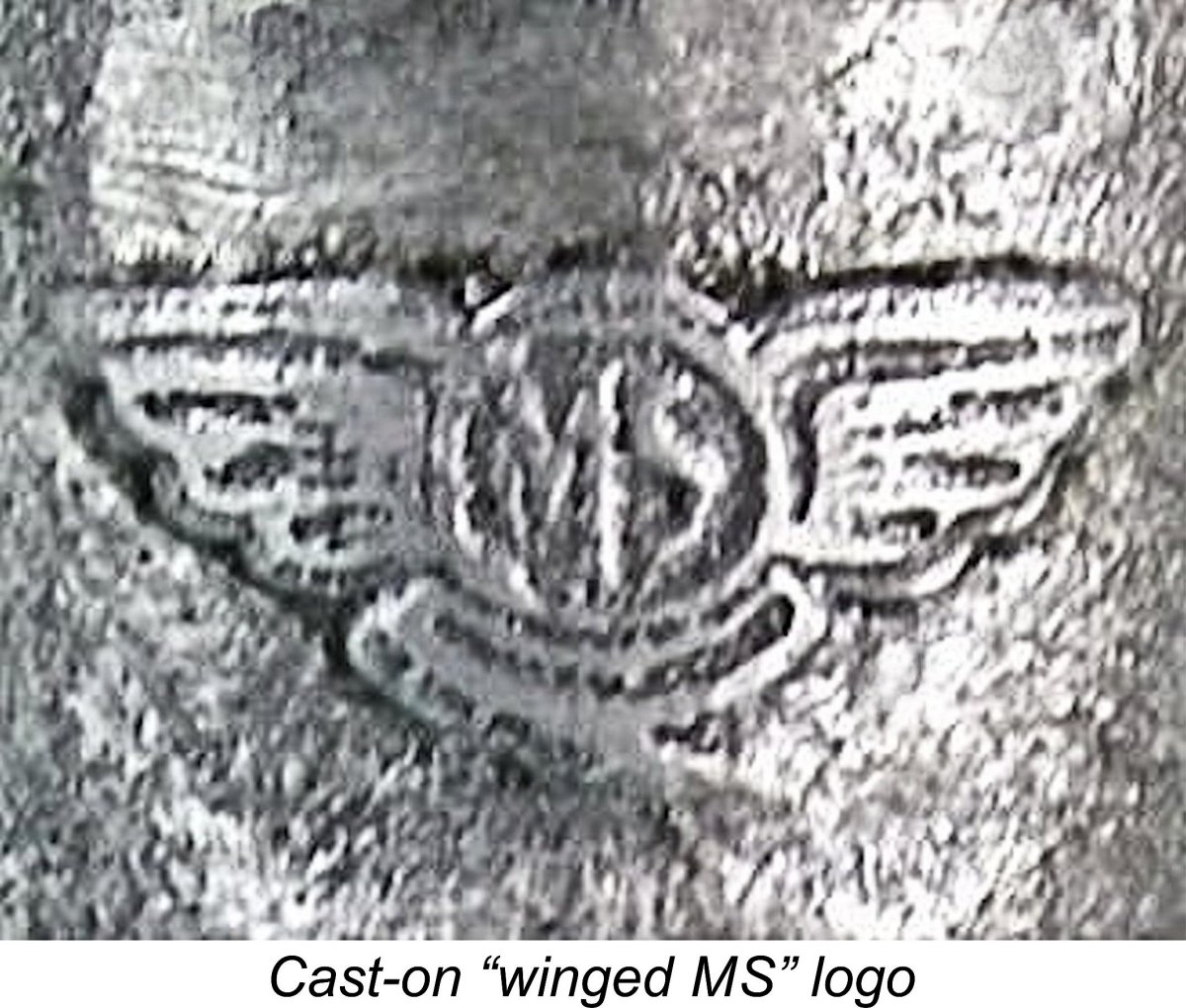
The engines bore the “winged M.S.” logo cast in relief both onto the left-hand side of the upper crankcase below the exhaust stack and onto the fuel tank top. They also bore serial numbers. My example bears the number 62 stamped both on the front of the crankcase's cylinder mounting flange and on to the rear surface of the screw-in backplate. Graham Podd's example carries the serial number 73. These are the only serial numbers for this model of which I am presently aware. The fact that the same serial number is stamped both onto the crankcase and the backplate clearly implies that the backplates were matched to individual crankcases through selective fitting. When the screw-in backplate is fully tightened, the mounting lugs have to be appropriately positioned to allow access to all four mounting holes. Seemingly once a backplate was found for a given case which established the correct orientation when fully tightened, both crankcase and backplate were stamped to keep them together from then on. All in all, this is a very interesting engine which displays a number of highly individualistic features. Moreover, the general standard of its construction is very high, as it needs to be with a design of this complexity. But what does it all amount to in operational terms? Let’s find out - off to the test bench!! The M.S. 2.5 Diesel on Test
Looking back over my test results for diesels of a similar type and displacement, I decided that the American C.I.E. 10 diesel of an identical 2.41 cc displacement might provide some useful guidance. The C.I.E. features a generally similar functional design, differing chiefly in the means of compression adjustment. On test, the C.I.E. turned a 10x6 Taipan prop at 6,400 rpm, leading me to believe that a 10x6 might be a very suitable prop with which to begin my test of the M.S. 2.5. This proved to be an accurate assessment. The test example (engine no. 62) had clearly been mounted and had done a fair bit of previous running. There was a little detectable play in the rod bearings, but nothing to raise any concerns. Compression seal was excellent, while the fit of the shaft in the eccentric bearing sleeve appeared to be beyond reproach. That said, the engine did exhibit one problem which had the potential to affect the testing. This was the fact that the very thin flange on one side of the split with which the pivoting tension of the timer arm can be adjusted had broken off at some point and had been neatly repaired using some kind of adhesive. While cosmetically excellent, this repair was of unknown structural integrity since I had no information Happily, there was a fair degree of resistance to arm rotation as matters stood, presumably due to the pressure exerted by the previously-mentioned grub screw which secured the control arm to the bronze main bearing bushing. Indeed, I actually got the impression that the split in the timer arm mounting boss may be redundant - the grub screw alone might well suffice. As described earlier, the system was configured to increase compression by turning the arm in the running direction. This would both set up the optimal Desaxe alignment of the shaft and create a pressure-induced couple opposing any friction-based tendency of the bearing sleeve to turn with the shaft (see earlier discussion). All of these considerations led me to hope that all might be well. The next problem which I faced was mounting the engine for testing. Obviously, a conventional test stand would not work given the engine's radial mounting. Moreover, the close proximity of the tank to the backplate left little room for a bulkhead against which to mount the unit.
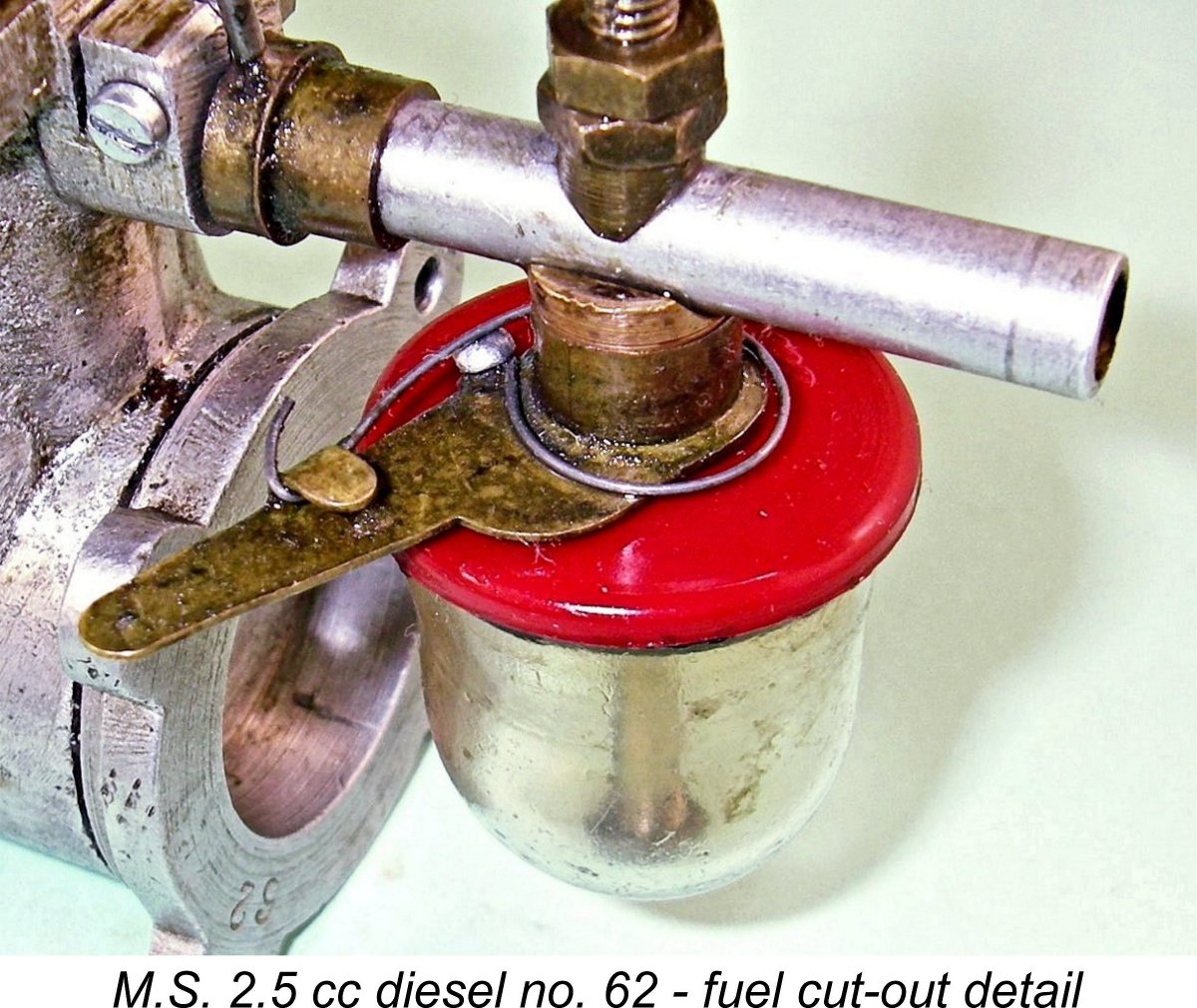
Having no information regarding the manufacturer's fuel recommendations, I elected to go with my usual "early sideport" diesel blend consisting of equal parts of ether, kerosene and castor oil. Most engines of this type and era will operate quite satisfactorily on such a blend. The high oil content would also be very kind to this engine's 72 year old working surfaces. The brass fuel pickup tube on the M.S. is a hollow blind-bored extension of the spraybar which does double duty both as the tank fastening bolt and the fuel supply line. It communicates with the tank through a pair of small laterally-drilled holes aligned with the bottom of the tank. Since the tank top, the fuel cutout and the tank itself are all secured by the same tube using a 4 BA nut on its externally-threaded lower end, the engine can only be operated with the standard hang tank in place. Operation with a separate tank would require the making of a replacement spraybar having a conventional fuel nipple. Fortunately, the fuel supply system on this near-perfect example proved to be in excellent working order, allowing me to use the standard hang tank throughout this test.
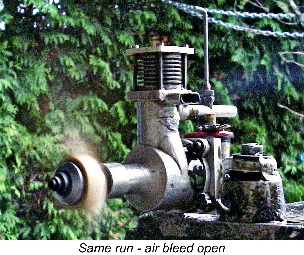
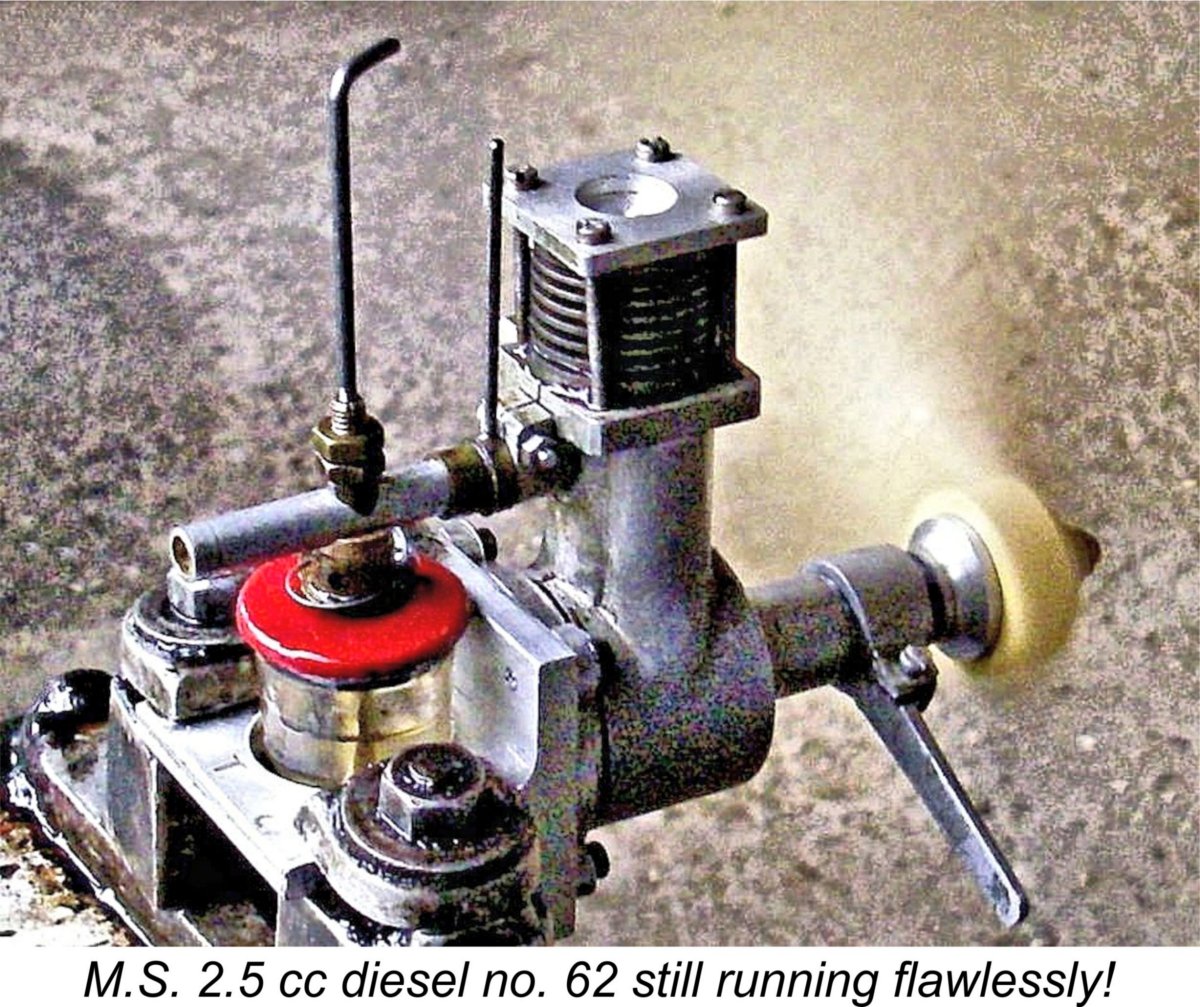
A couple of choked flicks followed by a modest open-port exhaust prime proved to be the best approach. Even when this was done, one had to flick for a while with no result whatsoever. Then out of the blue, the mixture in the cylinder would hit the sweet spot and the engine would suddenly roar into life with no preliminary popping or short-bursting. You never knew when this was going to happen - you just flicked until it did! Happily, it never took much flicking to get the engine going, especially after the settings had been established. Four or five flicks generally sufficed. Once I got the M.S. running, I very quickly got on top of the air bleed control. For finger choking to be effective, the air bleed obviously had to be closed for starting. However, further experimentation revealed that this control actually provided a very useful form of mixture adjustment. The engine liked to have a relatively rich needle for starting, with a smoky exhaust and slow, rather rough running. The above illustration provides a good impression of this! Once running, one's normal course of action would be to lean out the mixture using the fuel needle, a procedure which can of course be followed. However, in the case of the M.S. a far better approach was found to be to leave the fuel needle setting alone while progressively opening the intake air bleed both to lean out the mixture and also increase the flow of air into the engine. There was no need to touch the needle at any time to obtain smooth running - the air bleed control provided a very effective and convenient form of mixture control. It was perfectly possible to establish smooth running using the needle valve with the air bleed closed, but the engine ran noticeably faster on a given prop with the air bleed wide open and the needle set accordingly.
In the absence of access to an instruction manual I can't be certain, but I strongly suspect that this was the intended mode of operation - it's hard to discern any other purpose for the air bleed control. It certainly isn't set up to function as a cut-out, nor would there be any purpose in providing a second cut-out. In fact, this system is very user-friendly indeed once you get the hang of it - the air bleed provides a very quick and precise means of adjusting the mixture. Overall, I'd rate this as an extremely easy engine to handle, albeit one that takes a bit of initial familiarization. The compression control proved to be very positive in action. The best running setting was found to be just a little over half-way around the available range of travel, leaving plenty of adjustment potential in both directions. It also more or less corresponded to the maximum lateral displacement of the shaft towards the exhaust (compression) side, thus optimising the benefits of Desaxe operation. The fixed elevation of the cylinder head was clearly very well chosen. The M.S. held its compression settings perfectly, indicating that the opposing frictional and pressure-based torques acting on the main bearing sleeve (see above discussion) were in good balance. The engine actually started and ran at the same compression setting on a given fuel and prop, further simplifying operation once the setting was established. After a few familiarisation runs, I was easily able to find the best running settings for each prop tested. All figures were obtained with the air bleed wide open, allowing the engine to breathe as freely as possible. Running qualities were excellent, with smooth consistent running which was completely free from any tendency to sag. The exhaust remained nice and clear throughout, while the engine ran the tank out cleanly at all times unless the cut-out was activated first to stop the engine for a prop change. Noise levels were relatively modest too. Vibration levels were noticeable but were actually less than I had been expecting given the very long stroke and seemingly hefty piston. The counterbalancing of the crankweb is clearly quite effective. The sight of one of these engines actually running is so rare that I saw it as an obligation to share the experience as best I could by posting a video clip. This may be viewed through this link. The engine is on a slightly rich and under-compressed shake-down run in this video, hence the occasional misfire.
One feature that greatly simplified testing was the fact that the fuel cut-out worked perfectly. The redoubtable Lawrence H. Sparey had endless trouble with fuel cut-outs during his career as the resident engine tester for "Aeromodeller" magazine. However, even Sparey should have been able to get this one to work! The rotation of the spring-loaded arm turns a sleeve which opens a pair of holes near the top of the fuel tube. This action admits air to the fuel line, thereby destroying fuel suction. There's a very brief delay as the engine consumes fuel already in the system, after which it stops dead. Very convenient for prop changes! The following data were obtained on test.
It was clear that the engine was approaching its peak in the vicinity of 7,200 rpm - in fact, that probably was the peak. This being the case, I elected to terminate the testing with the 9x5 prop. Indications are that the engine developed around 0.098 BHP @ 7,200 rpm. This certainly beats the output of the contemporary 2 cc E.D. Mk. II, the more powerful Comp Special version of which did not appear until December 1947. It also pretty much duplicates the output of the contemporary 2.2 cc Majesco 22 diesel, albeit at a slightly higher speed. Finally, it's very close indeed to the 0.105 BHP @ 8,000 rpm measured for the American C.I.E. 10 diesel of an identical 2.41 cc displacement. It also outperformed the Mills 1.3 Mk. I which was one of its major sales competitors despite the lesser displacement. Overall, it's clear that the M.S. 2.5 cc diesel was well in the hunt among contemporary sideport diesels of similar displacement, at least in terms of performance.
The problem facing Charlie Lutman in pricing this engine was doubtless the relative complexity of its construction. When coupled with the high standards of workmanship to which Lutman was clearly and commendably dedicated, this would have made it a very expensive engine to produce. It's probable that the engine couldn't be any more keenly priced while still allowing for some profit to the manufacturer. It was likely the realization of this that led to the unit's early departure from the scene. Anther factor may well have been the M.S. 2.5's general styling. It is undeniably a rather "busy" design with a certain lack of elegance in its overall appearance. Moreover, its inherent suceptibility to crash damage would have been readily apparent. Such factors undoubtedly do influence consumer descisions to a significant extent. Finally, the engine was evidently sold more or less exclusively through the Newcastle hobby shop that brought it into existence, never being distributed on a national basis. This would have restricted its buyers to those living in the Newcastle area - modellers elsewhere would naturally buy whatever was available in their local shops. Setting aside the above comments and looking at the engine objectively as a model powerplant, there's no doubt that it was a very well-made and highly original design which handled extremely well and would doubtless have given good service provided one could keep it out of the Big Green Thing. Its failure in commercial terms takes nothing away from the respect due to Charlie Lutman for bringing this fascinating project to fruition! I thoroughly enjoyed testing one of the rarest and most unusual commercially-produced model engines which it has ever been my privilege to handle! Further Developments - the M.S. 1.24 cc Model Appears (Briefly!!)
Reading between the lines, it’s apparent that this model also failed to excite the aeromodelling public. Smaller advertisements appeared in the May and July issues of “Aeromodeller”, but nothing more was heard of the engine thereafter. It appears that only a single relatively small batch was ever manufactured and that they were all gone by August or September 1948. It’s perhaps revealing that in the Model Shop’s January 1949 advertisement for their M.S. Cobra C/L kit, the model was cited as being suitable for the Mills 1.3 - no mention of their own 1.24 cc offering.
In addition to the M.S. 1.24, the recommended engines for this design included such obscurities as the Foursome 1.2 cc model and the Milford Mite 1.4 cc design. Miles Patience recalled having built an example of this model some 30 years ago by copying from the illustrated kit, although he used an AMCO .87 in his rendition. The inclusion of the M.S. 1.24 in the list of recommended engines for this kit is explained by the information printed on the surviving sealing tape for the kit box. This indicates that in addition to being the manufacturers of Olympic kits and the full range of J. S. products, the company were wholesale agents for M.S. and their Keelbild kit range. In view of its seeming disappearance well prior to the end of 1948, the M.S. 1.24's previously-noted appearance in the 1949 revised edition of Col. C. E. Bowden's book "Diesel Model Engines" seems a little odd - the engine had long been out of production by that time. Regardless, Bowden stated that he had tried one of these engines and found it to be "a good starter and reliable runner". He also commented favourably upon the engine's light weight, compactness and ease of mounting. Once again, I don’t have anywhere near enough serial number data to make an estimate of actual production figures. All that I can report is that my example bears the number 69 stamped this time onto the top surface of the intake manifold, while Miles Patience reports the existence of similarly-stamped engine number 105. It seems highly unlikely that total production got very far past three figures. The engine is extremely rare today, although perhaps a little less so than the earlier 2.41 cc model. Let’s have a closer look at this rather ephemeral unit. The M.S. 1.24 cc Diesel - Description
One area in which the M.S. 1.24 cc model moved closer to mainstream thinking was its abandonment of the eccentric bearing compression adjustment system in favour of a conventional comp screw and contra-piston of the familiar type. This was most likely a cost-driven modification. In the advertising images, this control was fitted with a lock-nut to retain settings - a very worthwhile feature. My example lacks this refinement, nor does it seem to need it. Another step forward in production terms was the use of gravity die-casting for the crankcase. The 2.5 cc model had used sand-castings throughout, but my example of the 1.24 cc model is undoubtedly built around a gravity die-casting of very good quality. This makes it appear that the manufacturer was anticipating somewhat larger-scale production than had been achieved with the earlier 2.5 cc model. Beginning with the tale of the tape, we encounter a degree of uncertainly once more. Ron Warring did not provide bore and stroke dimensions for this engine in his Appendix II, again creating the impression that he never examined an actual example. Measurements taken by Ken Croft from the original example which he used as the basis for his superb replica (see below) yielded bore and stroke dimensions of 0.436 in. (11.07 mm) and 0.524 in. (13.31 mm) respectively for a calculated displacement of 1.283 cc (0.078 cuin.).
If my suspicions are correct, then any departures from these nominal figures may be down to “lathe operator’s license”, especially with a limited-production item like this one. Ken’s measured stroke may be a reflection of this - 0.524 in. does not correspond to any fractional figure. Given my unwillingness to dismantle my example, I’m unable to resolve this matter one way or another, nor does it really matter very much anyway! We’re close, and we know that the engine was a significantly less exaggeratedly long-stroke design than its 2.41 cc predecessor. That’s all that should concern us. My one concession to historical accuracy is my acceptance of the manufacturer's cited 1.24 cc displacement figure, however that was achieved. Warring cited a weight of 4.5 ounces for the engine. This is wildly at variance with the weight of 27/8 ounces (81.5 gm) claimed in the advertising. Giving the deciding vote to the engine itself, my complete and original example splits the difference by weighing in at 98 gm (3.46 ounces) all complete as illustrated. Not much agreement here, but I'll defer to the opinion of the actual engine!
However, the similarities end there. The cylinder porting is quite different, now following the reverse flow scavenging system as opposed to the cross-flow loop scavenging of the larger model. The induction port is located at the front of the cylinder, with the two drilled transfer ports and associated bypass passage being located at the rear. Two "race track" oval exhaust ports are now provided, one on each side of the cylinder. The use of a conventional contra piston eliminates the need to mount any timing control at the front of the main bearing. It also means that the engine's port timing is fixed, unlike that of its big brother described earlier. Accordingly, figures can be given in this instance. The exhaust ports open at around 110 degrees after top dead centre for a generous total exhaust period of some 140 degrees. The two drilled transfer ports overlap the exhaust almost completely, providing a relatively long transfer period with a very short blow-down period. The most unusual aspect of the engine's functional design is found in the induction timing. The induction port opens at around 45 degrees before top dead centre for a total induction period of 90 degrees. This is pretty conventional for a sideport design -- the real surprise comes when one discovers that the engine also has a pretty massive sub-piston induction period of some 50 degrees, extending 25 degrees either side of top dead centre. The result of this is that the engine only draws mixture solely from the carburettor for some 20 degrees of crank angle before the sub-piston induction cycle begins.
It's interesting to note that the example in Ken Croft's possession from which he developed the Motor Boys plans for the M.S. 1.24 cc model (see below) apparently did not feature sub-piston induction. To offset this, it had a slightly longer induction period. It also incorporated a substantially longer overlap between the openings of the exhaust and transfer ports. It would appear that there was some variation between different examples of the engine. Following the original publication of this article, Ken advised that the serial number of that example was 105 - some distance from my own engine no. 69. It thus appears that at least 105 examples of this model were manufactured. Any more serial numbers out there?? I also heard from Miles Patience, who was able to confirm that engine no. 105 ended up in the collection of his late father Mike Patience.
The tank is fitted with a neat base for a screw-in filler cap. Both base and cap are moulded from black plastic. Some other examples feature a spring-loaded Gits-style cap in place of the plastic items. A metal spigot is incorporated to provide a means of connecting the fuel tubing to the tank. The tank can be secured in any radial orientation to suit that of the engine when mounted. Presumably this is the basis for the manufacturer’s advertising statement that this is “the engine that will run in any position”. A somewhat strange point to emphasize in a promotional context - the same could be said of almost any engine then on the market!
The prop driver engages at the rear with a small and rather sharply-angled self-releasing taper formed on the front of the crankshaft journal. A steel nut and alloy prop washer are used to secure the prop against the driver. The design allows for some slippage in the event of a crash impact, thus offering some protection to the shaft. Another front-end refinement which appears on my example but has never drawn any previous comment is the neat little moulded plastic spinner. I'm absolutely certain that this spinner is original, being perfectly matched to the engine and being made of the same material as the tank filler cap and seat. This is not the actual prop tightening component - that chore is handled by the previously-mentioned steel nut and alloy washer. The plastic spinner is a purely cosmetic refinement which is only screwed on finger-tight. No doubt most owners either dispensed with them as an unnecessary inconvenience or broke them the first time the model hit the ground! Several members of the Komet range from Sweden were later to use a similar fitting.
The needle itself is formed from a slot-head 8 BA screw with a taper ground into its end. It is fitted with a brass control knob which is secured with a lock-nut.The needle carrier is split, with a coil spring being tightly fitted around it to maintain the pressure of the split section against the needle thread. It must be said that this system is somewhat less than effective........... We might initially suspect that the idea behind the forward-facing intake was to utilize the ram effect of the slipstream to improve the filling of the crankcase during the induction cycle - a rudimentary form of supercharging. This was not a new idea - it had been previously tried and promoted on the Melcraft 29 spark ignition engines from America, without any spectacular results. It was to be applied once again in the design of the I cc Zeiss Jena sideport diesel of 1960, to somewhat better effect. However, I personally consider it to be far more likely that this unusual configuration was actually chosen because, along with the front-mounted fuel tank, the arrangement provided a completely unobstructed flat surface at the rear to facilitate bulkhead mounting. No intake tube or tank to create mounting complexities - the overall length of the engine was unusually short for a sideport design. The engine is completed with a screw-in backplate which is recessed into the rear mounting surface. The radial mounting lugs are cast integrally with the main crankcase rather than being part of the backplate as in the case of the larger model. In all other respects, the M.S. 1.24 cc diesel is basically a conventional long-stroke sideport diesel of its time. Like its 2.41 cc sibling, the quality of its construction is beyond reproach. Fair enough - how well does it run? Let’s find out! The M.S. 1.24 cc Diesel on Test
This example appeared to be generally free from any structural issues that might affect its performance on test. The fact that the previous owner (a good friend of mine, since deceased) had given it a few runs led me to believe that I would have little trouble with it. However, the fact that this model too was radially mounted posed a challenge in getting it into the test stand! I accomplished this quite simply by drilling and tapping some extra holes into the face of the same bulkhead mount that I had previously used to test the larger M.S 2.5 cc model. The spring-loaded split thimble that is supposed to provide needle tension seemed to have no effect whatsoever. Anticipating problems from this source, I fitted a suitable coil spring which would do a far better job of retaining needle settings. I also elected not to use either the plastic spinner or the fuel filler cap, being anxious to avoid any risk of loss or damage. Mounted in the test stand with its Rev-Up prop fitted as planned, the engine felt really good when turned over but stubbornly resisted my initial attempts to get it started. I could easily get a firing burst, but the dratted little engine simply wouldn't keep running no matter what I did with the needle. I got the impression that suction was very much on the marginal side, just as expected given the massive sub-piston induction period and surface fuel jet noted earlier. If the needle was set too lean, the engine wouldn't draw fuel up Recognizing both the marginal suction and the fact that the standard tank imposes a considerable head against which the engine has to draw fuel when mounted vertically, I switched to a separate tank in which the fuel level could be matched to the spraybar elevation. This improved matters to the point that a start was soon achieved. I quickly learned that the needle setting for starting was unusually critical - even with the very fine thread on the needle, the setting had to be within a quarter turn of the sweet spot, otherwise the engine simply would not pick up and keep running. That having been said, once the setting was established, the engine proved to be a very good starter indeed. A couple of choked flicks were the only necessary preliminary. Once running, the little M.S. proved to be very responsive to the controls. Oddly enough, the needle setting for best running was far less critical than it was for starting - the optimum setting was well defined, but the engine kept running quite well either side of the sweet spot, merely slowing down a little. Once set, running was extremely smooth and consistent, with no sign of sagging. Vibration levels too were well within acceptable limits. Both compression screw and needle valve held their settings perfectly at all times - the spring that I had added to the needle valve assembly proved to be very effective, while the comp screw lock-nut seen on some other examples was not required. The following data were recorded on test.
As can be seen, the M.S. 1.24 cc diesel was found to develop some 0.046 BHP @ 7,700 rpm. This may not seem very impressive, but it actually almost matches the 0.048 BHP @ 6,400 rpm measured during my earlier test of the contemporary Mills 1.3 Mk. I Series 2 diesel. The Mills clearly out-torques the M.S., but the performance differential between the two models would be barely apparent in the field provided the two engines were both propped appropriately. An 8x4 prop would suit the M.S. very well for free flight, while a "slow" 7x6 would probably work OK for control line. The little M.S. came through this test with flying colours. No mechanical difficulties were experienced, nor was any excessive wear apparent - the exhaust residues remained completely clear at all times. Overall, a most enjoyable test of a very rare model diesel of excellent quality! The Motor Boys Replicas As usual with an interesting engine of this rarity, the members of Motor Boys International were not slow to pursue the concept of creating replicas of the motor. First into the breach was Ken Croft, who was fortunate enough at the time to have an original example of the M.S. 1.24 cc model on “permanent loan” from a friend.
The M.S. 1.24 cc diesel design has been preserved as a Motor Boys International style set of CAD drawings. These are included in the Members-Only Plan Book which is accessible through the link provided. It’s possible that other replica examples may have been built from these drawings. Graham Podd certainly did so. At the time when Ken produced his replica along with the drawings, no example of the M.S. 2.5 cc model was available for reference. Graham Podd told me that as received, his engine number 73 had a damaged induction tube clamping spigot at the rear of the crankcase. Before welding it to effect a repair, he cast a new crankcase "just in case". As it happened, the repair to his original case was successful, leaving his potential replacement case available to be used as the basis for a replica, which Graham duly constructed. That engine bore no serial number and was passed on to Richard Dalby. As far as I'm presently aware, it is the only existing replica of the M.S. 2.5 cc model. Ken Croft advises that he had an example of the M.S. 2.5 when in his late teens, but gave it away! The actions that one later regrets…….. I can think back to a few!! Conclusion
This being the case, the question might be asked why I bothered to write this article at all - it will have no more than academic interest for the vast majority of my readers. The answer is that the M.S. story is a very tangible part of the history of model engine manufacture in Britain - should it be ignored merely because the engines are so rare? Not in my opinion - I truly believe that the M.S. story fully merits preservation for its own sake. I am in a unique position to accomplish that goal, amounting in my book to an obligation to share my own good fortune with others to the extent possible. The engines themselves display a truly refreshing degree of original thinking "outside the box" by their talented designer Charlie Lutman. The quality of their construction speaks eloquently both to the skill and dedication to quality displayed by Lutman and his colleagues. Their memory deserves our utmost respect. I hope that you've enjoyed reading this previously obscure but very interesting story!! There are other tales to tell about some of the more obscure British model engine ranges such as this one, so I expect that this won't be the last such effort on my part! _____________________________ Article © Adrian C. Duncan, Coquitlam, British Columbia, Canada First published April 2020 |
||
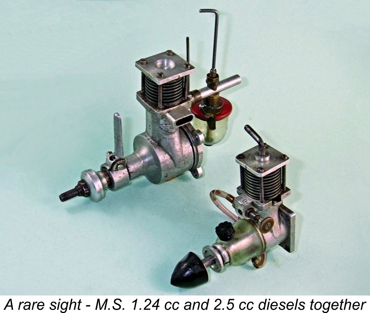 In this article, I’ll focus on a mega-rare and very individualistic pair of English model diesels that date back to the halcyon early post-WW2 years when aeromodelling was a widely-pursued mainstream hobby, creating market conditions under which hobby shops, as opposed to model engine manufacturers per se, found it economically feasible to offer their own “house brand” engines. We’ll be examining the M.S. diesels from Newcastle-on-Tyne in northern England.
 In these days of unprecedented economic and participatory challenges facing the aeromodelling scene as societal attitudes, available technology, competing interests and related market conditions continue to emerge and evolve, those of us who were fortunate enough to be “there” sometimes become a little misty-eyed thinking about what now appear in retrospect to have been the golden years of post-WW2 aeromodelling during the 1940’s, '50’s and '60's. This was a period during which aeromodelling (and indeed modelling in general) was among the most popular and widely-practised “hands-on” craft-based activities of them all.
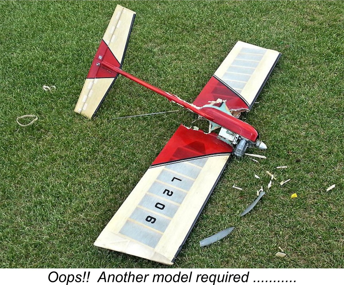 Of course, one model always led to another, so people kept going back for more as funds permitted (or necessity dictated, as in the illustration at the right!). Naturally, this in turn led to a highly competitive situation as far as the numerous shops were concerned – after all, they were competing for the ongoing attention of the same very considerable repeat customer base.
  capital to enable them to develop their own successful kit ranges, most notably Henry J. Nicholls Ltd. and Model Aircraft (Bournemouth) Ltd. with their respective Mercury and Veron kits.
  The M.S. diesels were produced and marketed during 1947 and 1948 by the Model Shop (Newcastle), then operating from premises at 3 Ridley Place on Northumberland Street in Newcastle-on-Tyne. This business was almost certainly the oldest model shop in England, having been established in 1924 by Charles “Charlie” Lutman at 2 College Road, Barras Bridge, Newcastle. It was also destined to become one of the longest-lasting such businesses, remaining in continuous operation under the same name and family ownership for over 80 years!
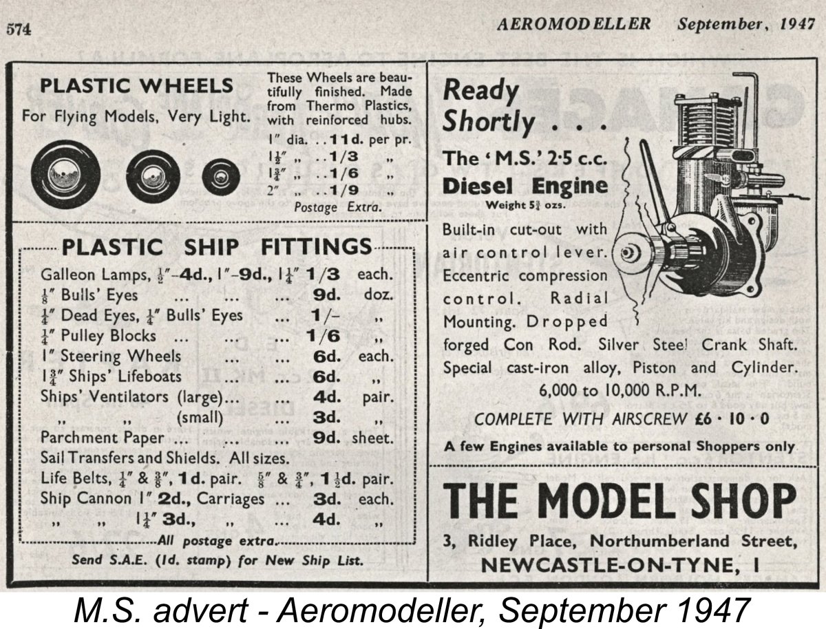 Quite apart from his ongoing Keelbilt kit range, the range of products offered by Lutman's company was very impressive, as a perusal of the attached “Aeromodeller” advertisements will confirm. In addition to the airscrews, pneumatic wheels and balsa cutters shown in the advertisements, the company made such accessories as fuel tanks and team race pilots as well as a wide range of model ship fittings. The late Ron Chernich recalled fitting a pair of giant M.S. 3½ in. dia. pneumatic wheels to his Junior 60 back in the steam-driven R/C days of vacuum tubes and rubber-driven escapements! I still have a few M.S. plastic fuel tanks in my "curiosity" collection.
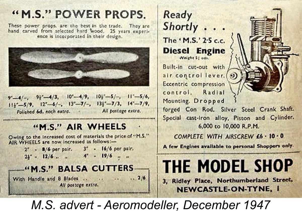 time), since a few completed units were said to be available to personal shoppers at the Ridley Place store at the time of the advertisement’s submission to the magazine in August. The quoted price of the engine was £6 10s (£6.50) complete with a matching propeller of unspecified size.
 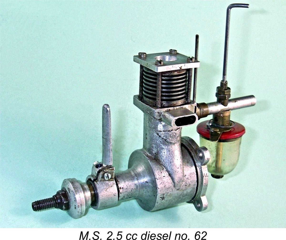 The rarity of the M.S. 2.5 cc diesel is such that I have elected to avoid any risk of damage by leaving my complete and fully functional example in its undisturbed state. When this article was first published I was therefore unable to provide the usual level of detail. I had to content myself with including such information as could be gleaned from an external examination.
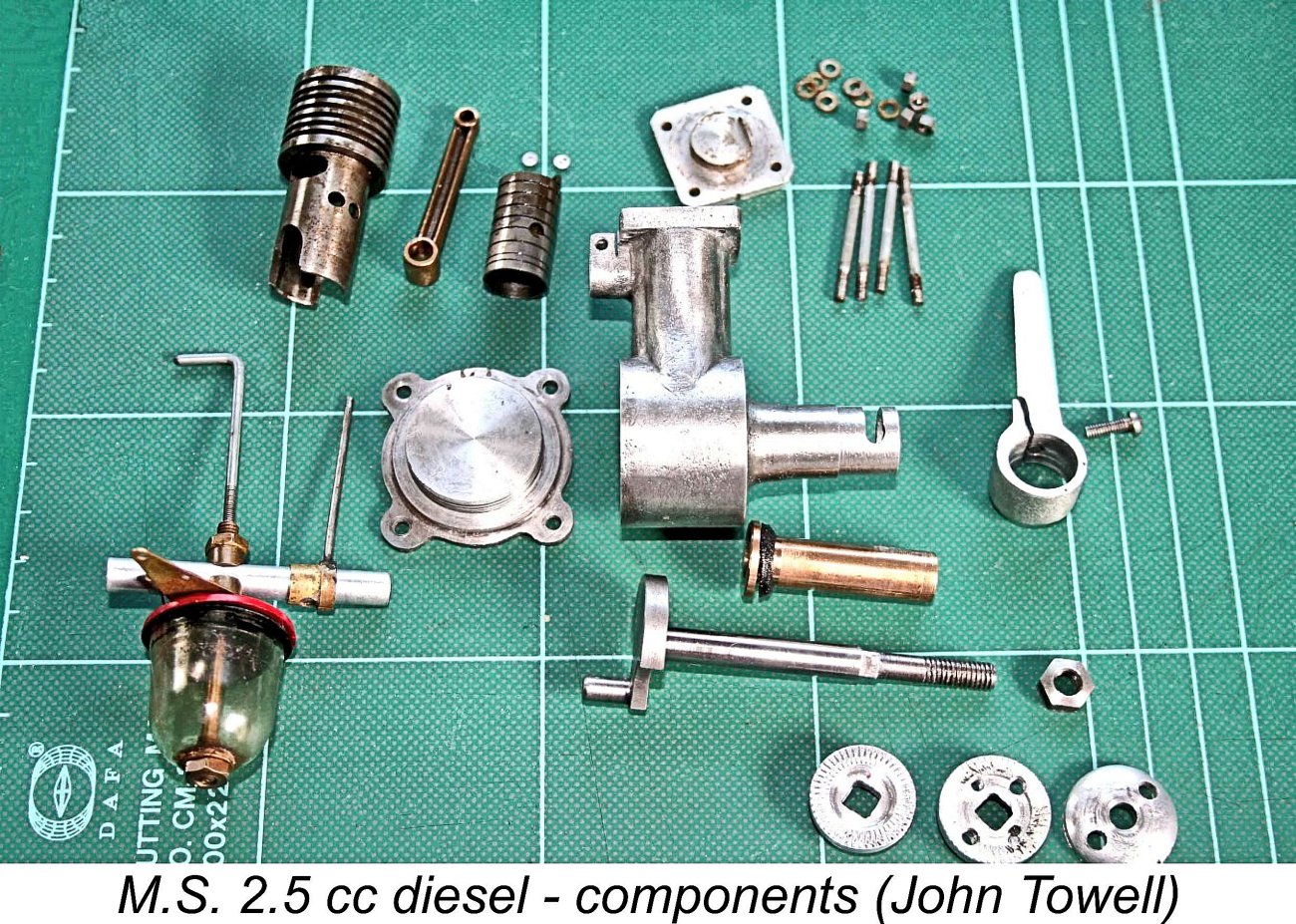
 Interestingly enough, the M.S. diesels were both included in the table of British diesels which formed part of Appendix II of Ron Warring’s January 1949 book ”
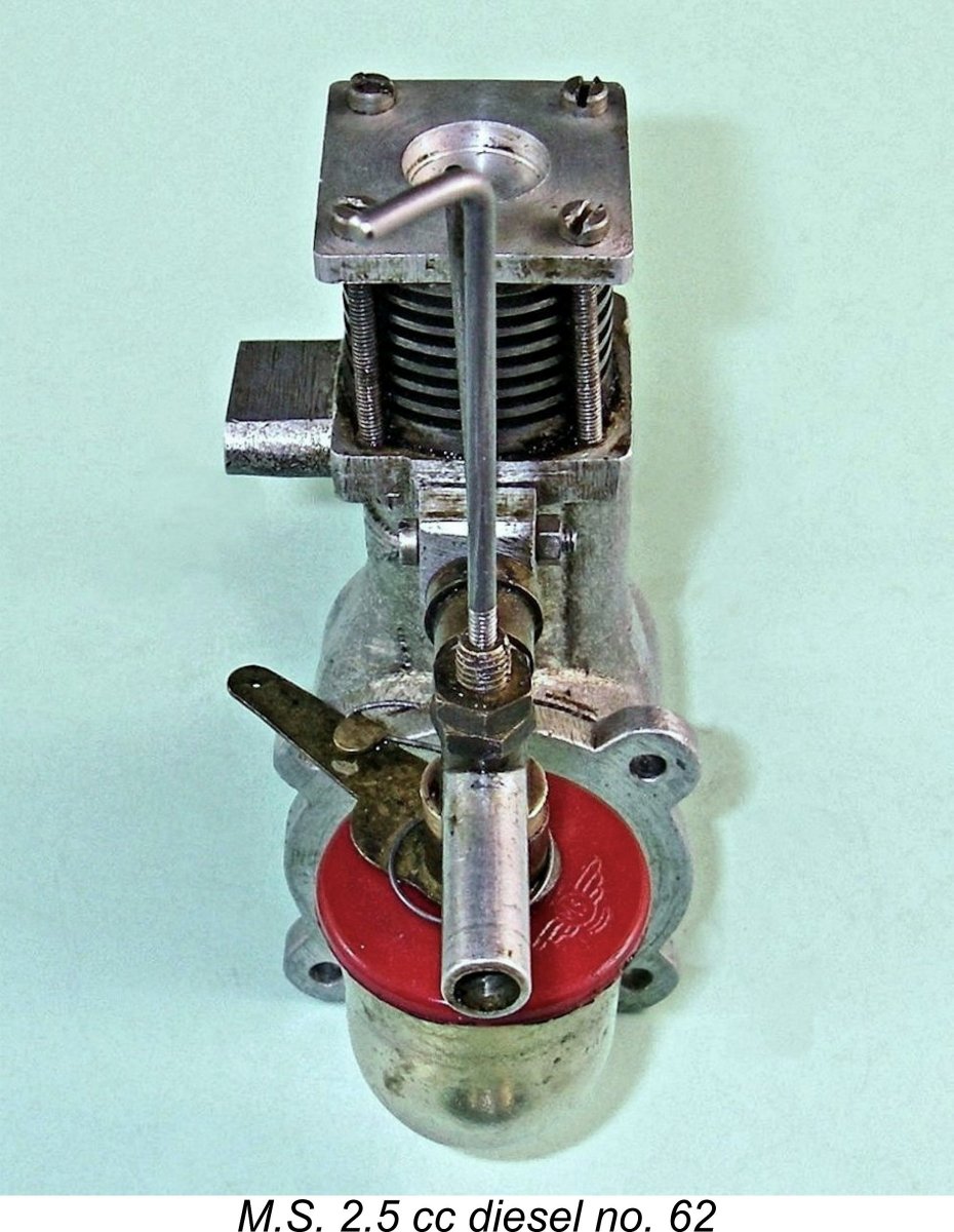 Structurally speaking, the M.S. 2.5 cc model (as I will continue to call it in deference to the manufacturer’s own advertised designation) presents a number of unusual features. Beginning at the top, the light alloy cylinder head has a square shape in plan view. Because compression adjustment is achieved by other means (see below), the head incorporates no provision for a compression screw, creating the initial across-the-room impression that the engine is a fixed compression job. Not so, as we shall see!
 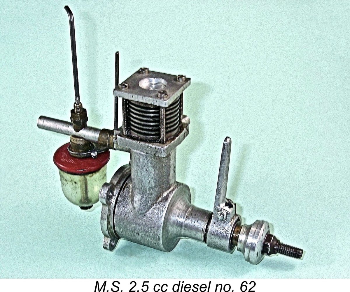 Perhaps the most unusual feature of the M.S. 2.5 is its use of the eccentric-bearing compression adjustment system. This arrangement was tried in a number of model diesels during the early post-WW2 period, including the
 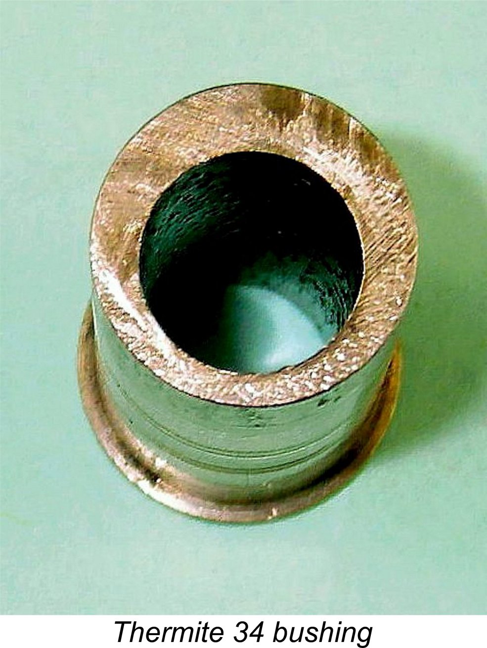 Such designs invariably include a long control arm located at the front of the bearing. This arm is secured to the bushing either by clamping or through some mechanical connection, constraining the bushing to rotate in the case as the arm is moved. Since the actual bearing itself is reamed eccentrically in the bushing, the effect of turning the bushing in the main bearing casting is to raise or lower the crankshaft relative to the rest of the engine, in particular the cylinder head. This in turn raises or lowers the working compression ratio by altering the elevation of the piston crown relative to the fixed cylinder head at top dead centre. In effect, the working piston does double duty as both the power and contra pistons, using the conrod as the compression screw!
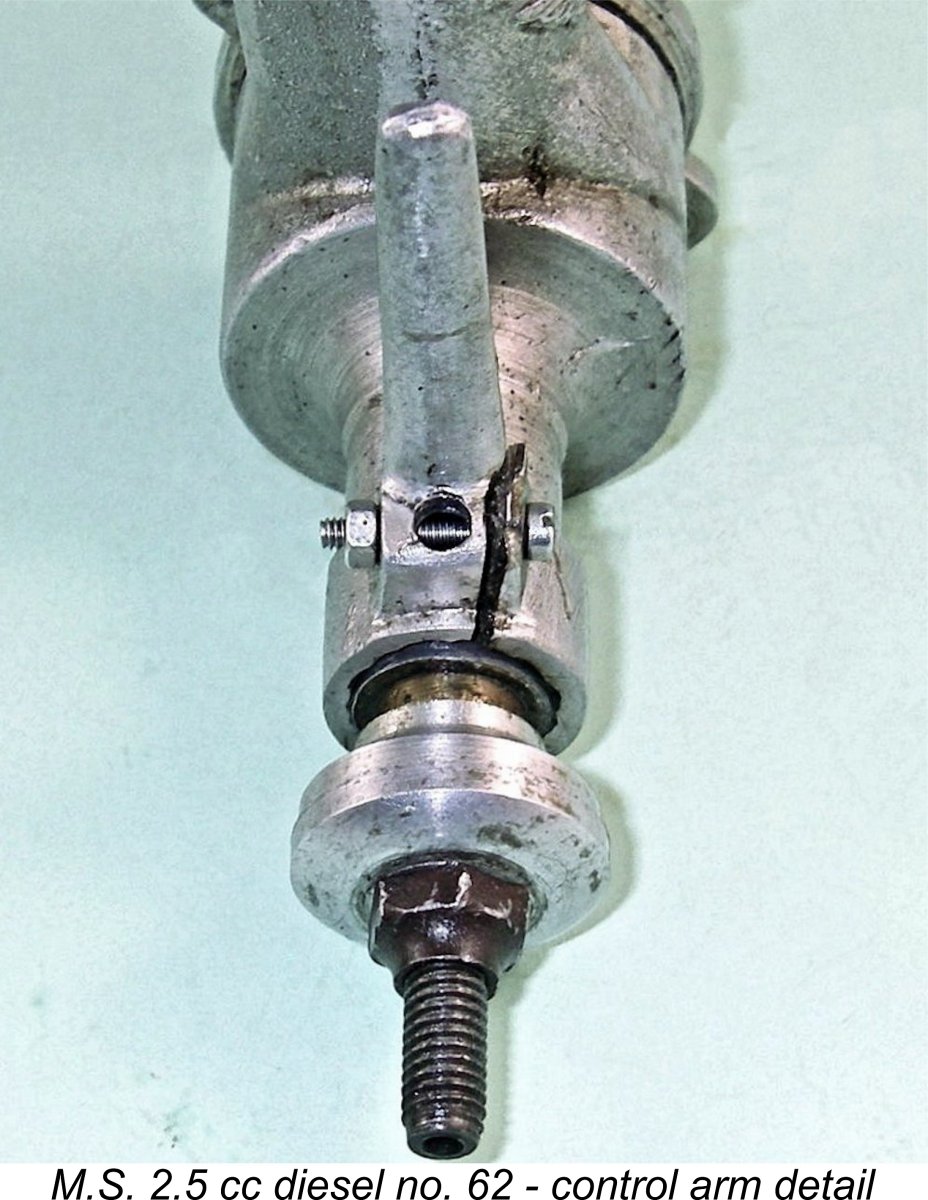
 But that's not the end of it! In order to communicate with the bushing, the grub screw passes through an annular slot milled into one side of the main bearing housing. This slot limits the radial movement of the grub screw, confining the timer arm to a maximum of 180 degrees rotation. On my example, the hole in the bushing is located such that with the arm in its vertical position as illustrated, the grub screw is up against the top end of the annular slot and the eccentric main bearing is at its lowest possible point. Hence this position of the timer arm corresponds to the minimum compression setting that can be accommodated - around 14:1.
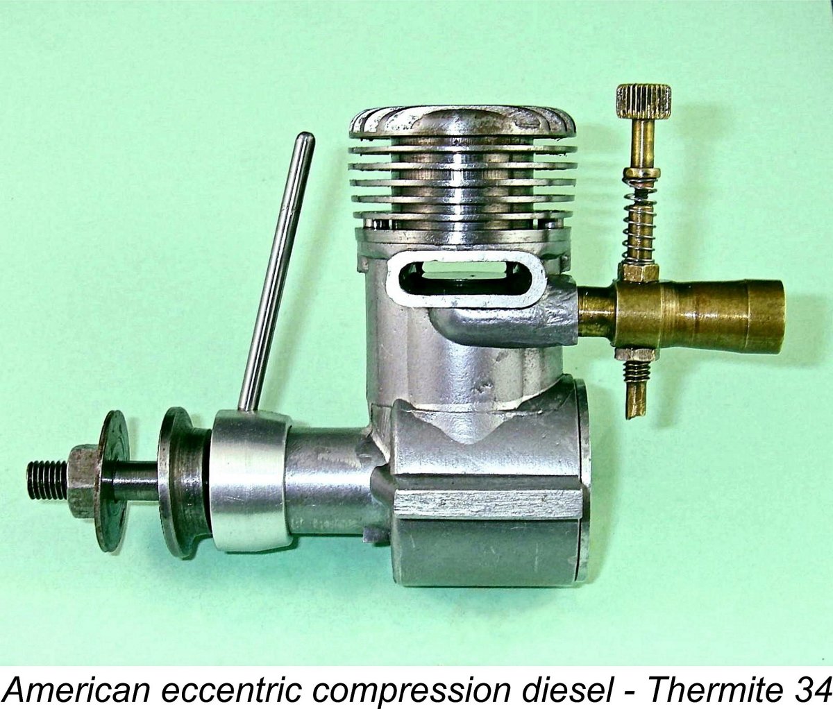 Another often-overlooked factor which will inevitably be affected by the application of eccentric-bearing compression adjustment is the lateral alignment of the crankshaft centre line relative to the cylinder axis. Engines featuring some degree of lateral crankshaft offset from the cylinder axis are known as
 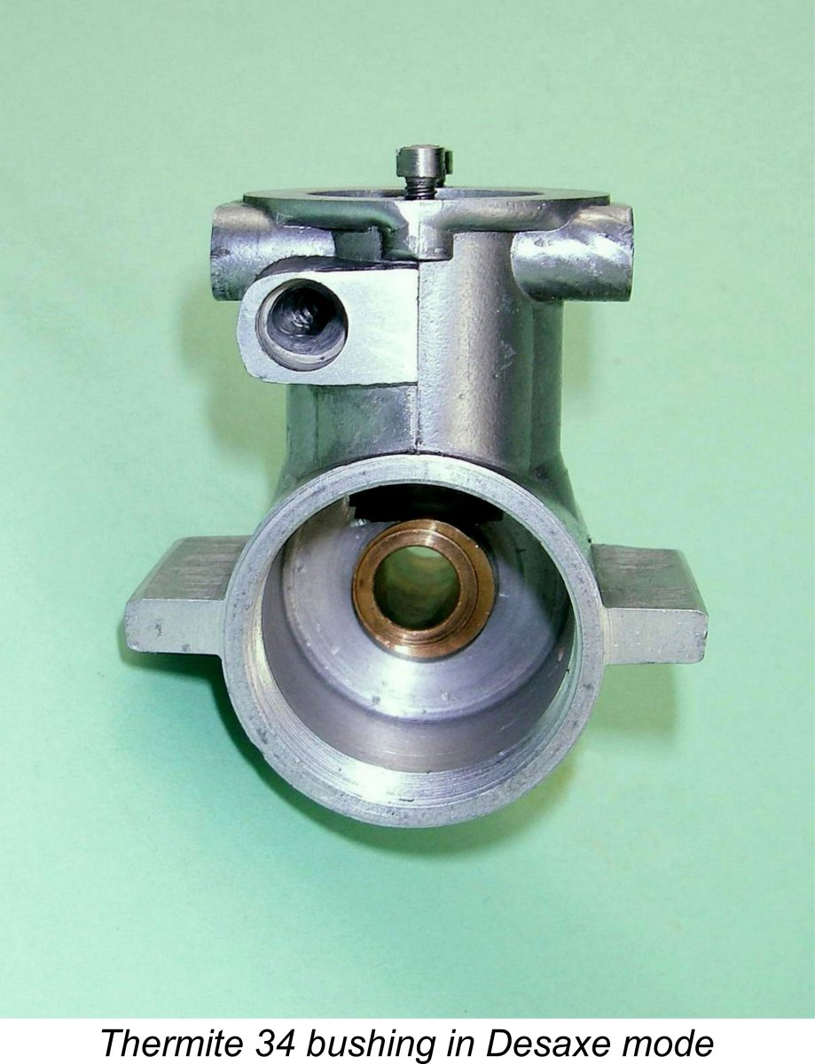 To take best advantage of the Desaxe effect, the bushing of an eccentric-bearing compression ignition engine having a centrally-bored main bearing housing should ideally be positioned with the actual bearing bore offset towards the compression stroke side, that is, towards the rear-view left-hand side of an engine intended for normal rotation. Another advantage of this configuration would be that any tendency of the bushing to rotate with the shaft due to main journal friction will be resisted by the counter-rotational couple created by the very considerable conrod pressure acting upon the offset shaft.
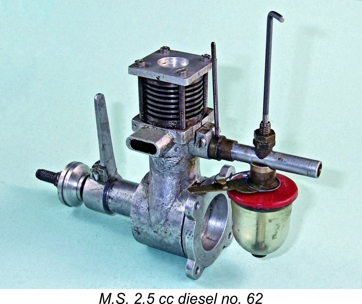
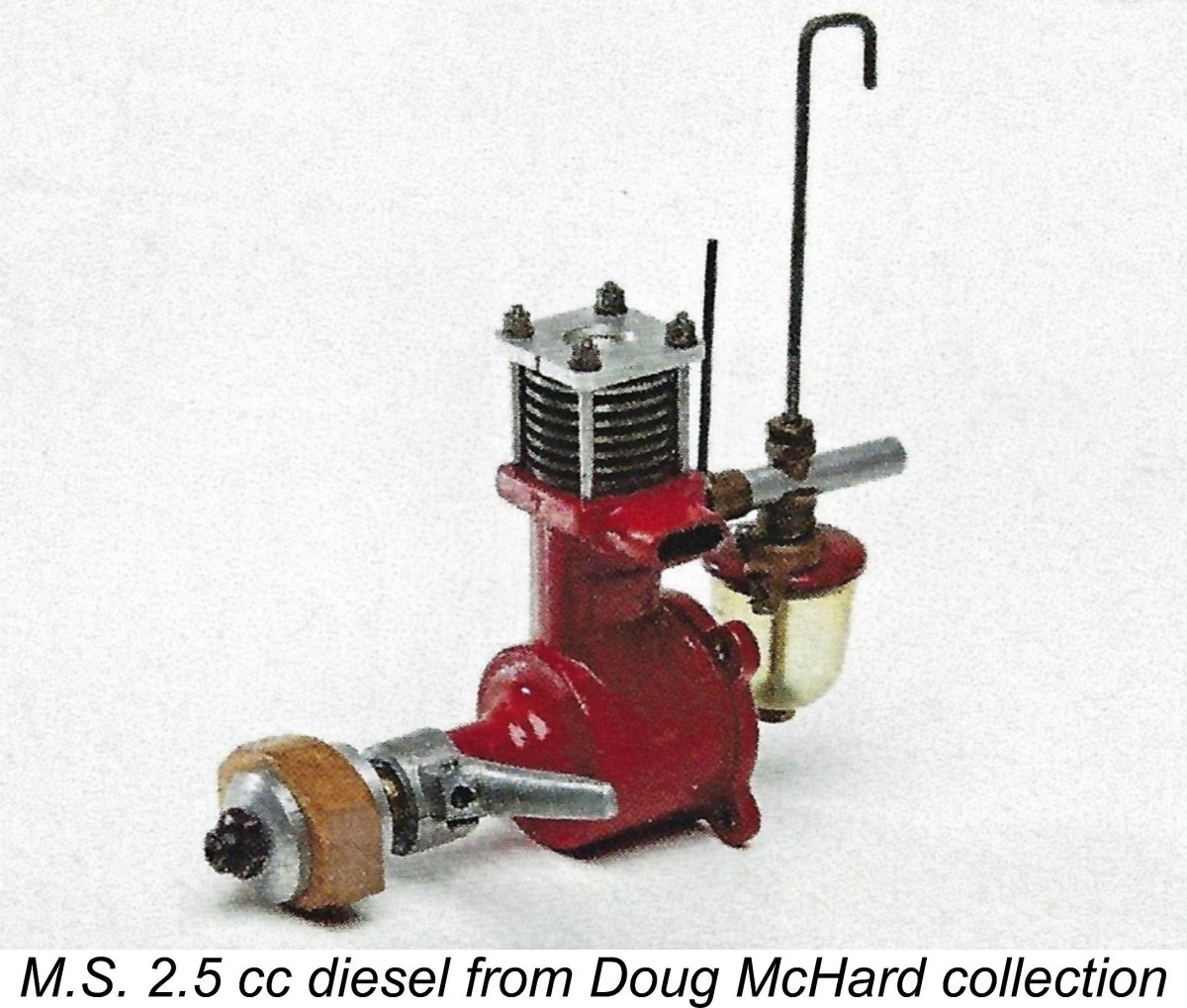
 The other interesting feature is the tank top, which is of laminated molded plastic. The underside is black, while the visible top layer is red. It appears that some of the engines themselves had red-painted crankcases, as witness Kim Watson's image of an example from the Doug McHard collection which is reproduced above. The crankcase of my own example shows no evidence whatsoever of ever having been painted.
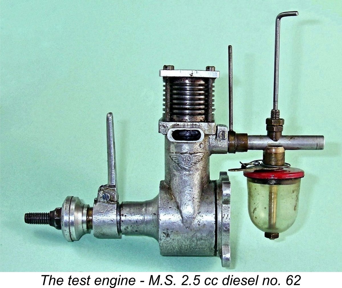 I went into this test with absolutely no guidance regarding the best prop sizes to try. Ron Warring’s previously-cited Appendix II table doesn't go so far as to include any prop recommendations for the M.S. 2.5. This reinforces the impression that Warring's data was poorly supported, seemingly having been recorded at second hand in the absence of any opportunity to examine and measure an actual example of the engine.
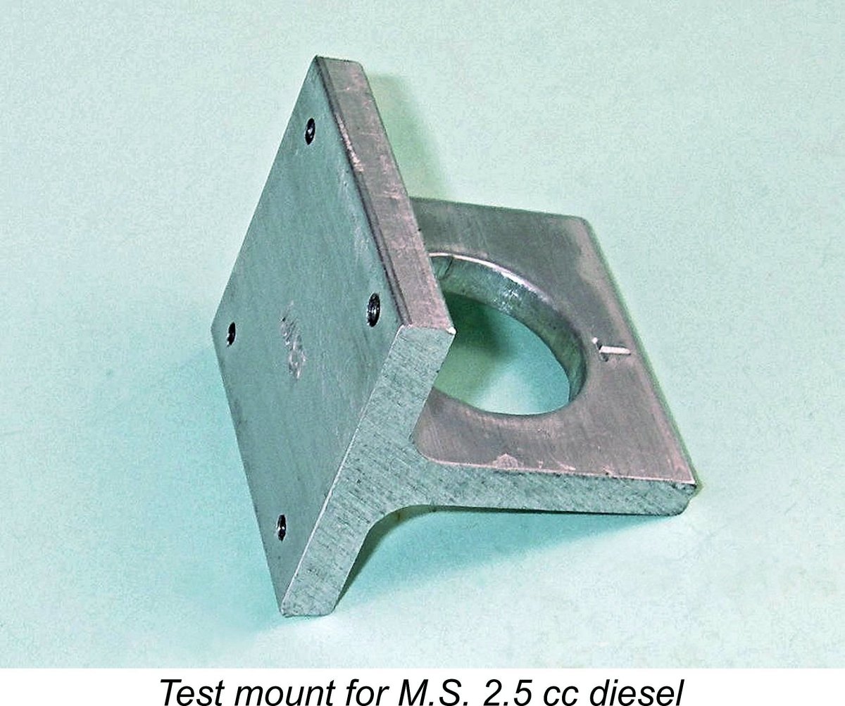
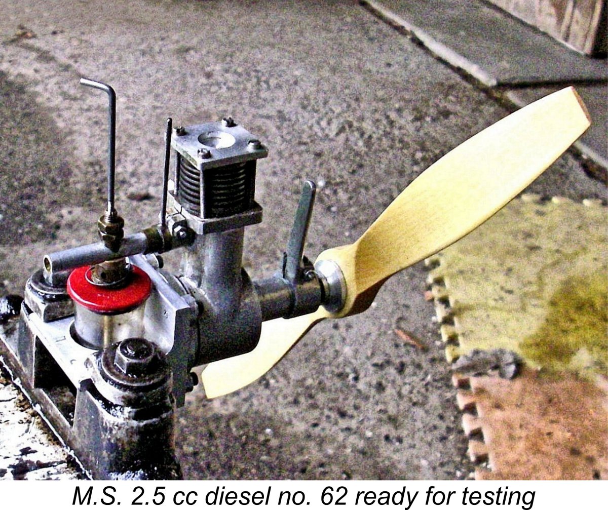 I ended up making the illustrated bulkhead mount from a length of extruded aluminium T-section, incorporating tapped holes in the mounting face to secure the engine. I added a large opening in the stem section of the T behind the mounting bulkhead to accommodate the tank. The stem section of the T could be secured in a conventional test stand. Hopefully the attached images will make this arrangement clear.
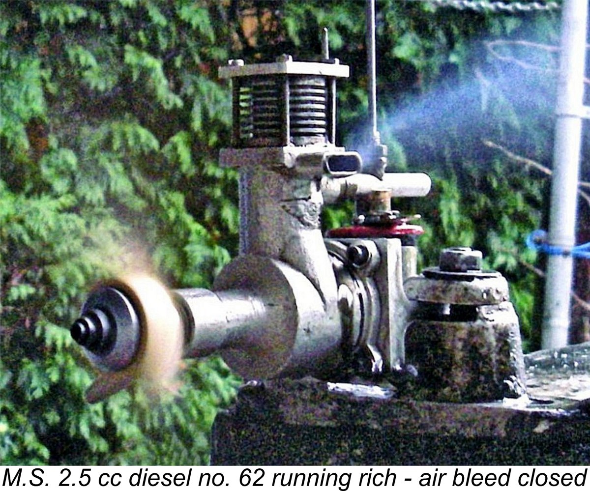
 I had no intention of subjecting this extremely rare engine to the rigors of an extended test. I contented myself with trying a small range of calibrated wooden props, the aim being to get the engine up to somewhere very near its peak. Once that point was reached, I saw no point in pushing the old beastie any further - why take a chance with such a rare engine?!?
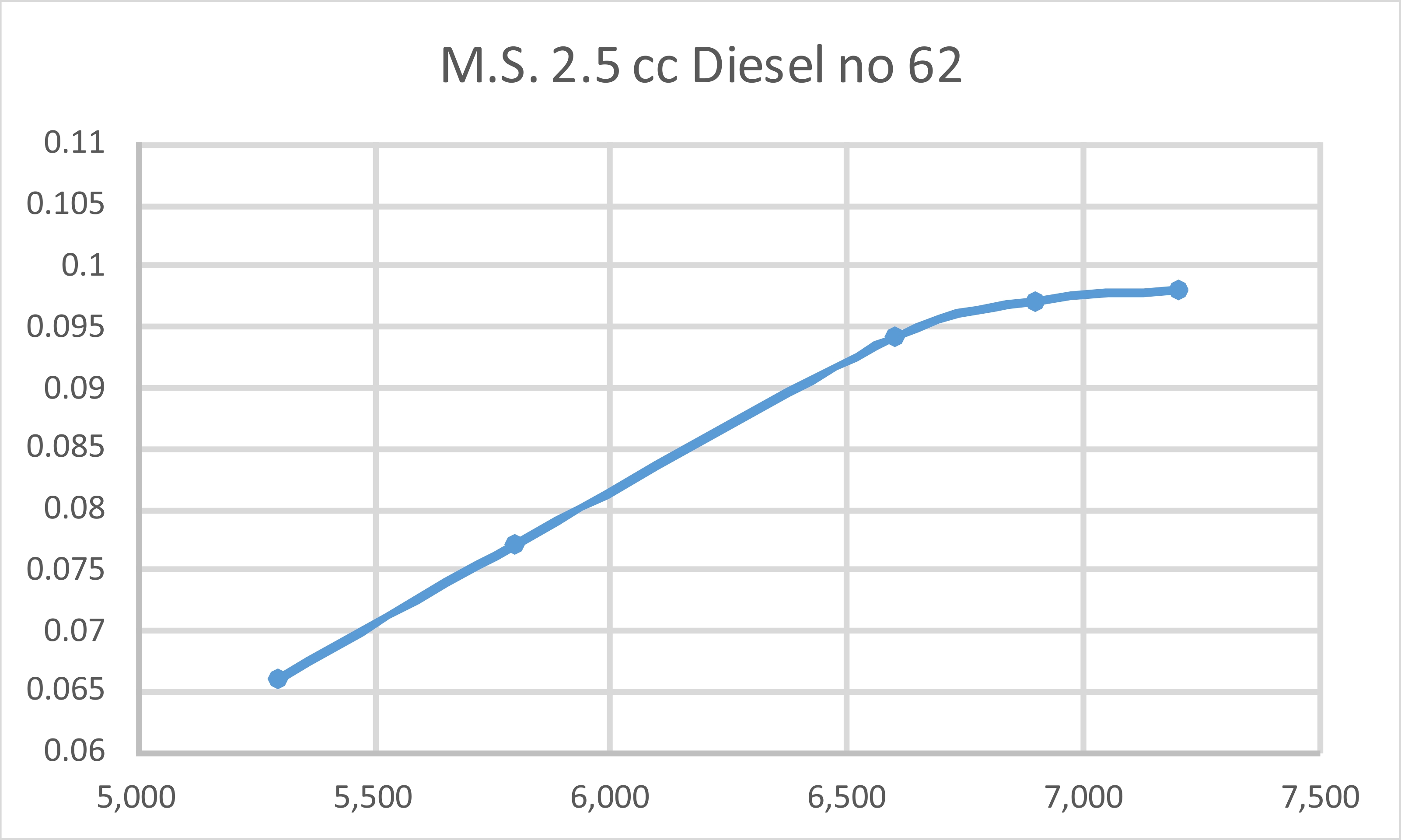
 So why did it fail in the marketplace? Probably for a variety of reasons. The most obvious of these is cost - at a price of £6 10s (£6.50), the engine was considerably more expensive than any of its contemporary rivals. As of late 1947, the 2 cc E.D. Mk. II sold for only £4 4s (£4.20), while even the relatively costly Majesco 22 undercut the M.S. at a price of £5 12s 6d (£5.62). Simply put, the M.S. 2.5 cc model was the highest-priced engine in its class.
 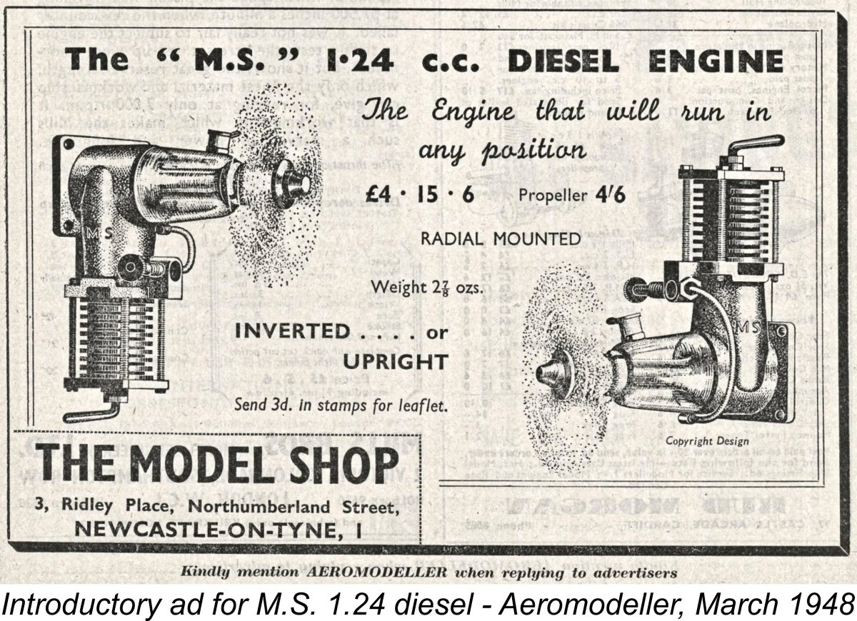 It’s apparent that even before the failure of the M.S. 2.5 to penetrate the market had become obvious, Charlie Lutman had already commenced work on a smaller model diesel of only 1.24 cc nominal displacement. The first batch of these engines was evidently completed by February 1948, since the engine was formally introduced through an advertising placement which appeared in the March 1948 issue of “Aeromodeller” magazine. The quoted price was £4 15s 6d (£4.77), with a matching propeller of unspecified size also being offered separately at a price of 4s 6d (£0.22). Perhaps significantly, the M.S. 2.5 cc model was not mentioned in this advertisement.
  That said, the engine was promoted as being suitable for at least one kit model. This was the Olympic "Nancy" control line model which was kitted in 1948 by the J. S. Model Centre of 6 Blenheim Grove, London, S.E. 15. You've got to love the enticingly risqué artwok on the box label - quite daring for 1948! Bet that sold a few kits .........
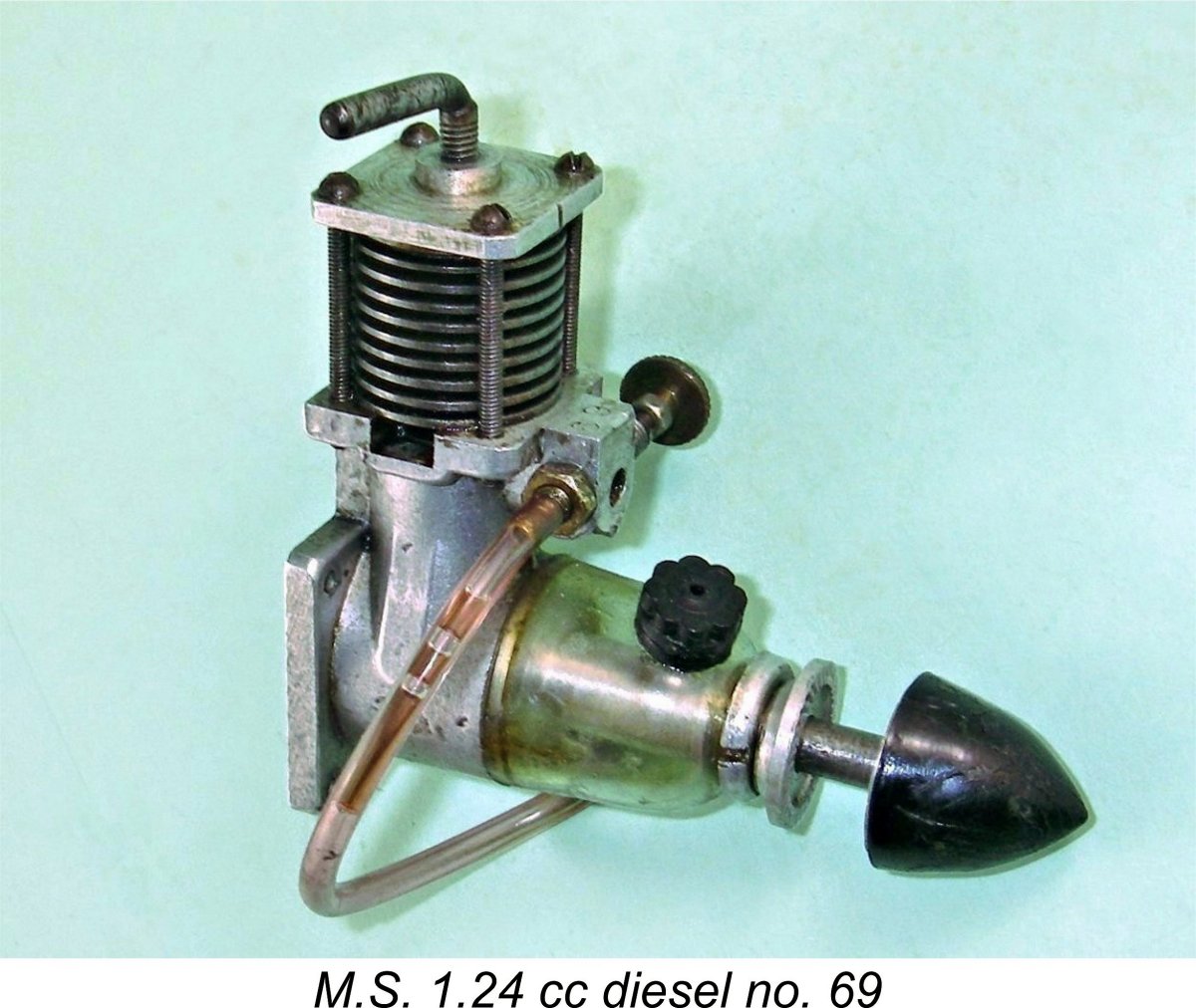 Under its somewhat individualistic-looking skin, the M.S. 1.24 cc diesel was basically a conventional sideport model, albeit displaying several highly unusual features. The most obvious of these was the intake location at the front of the crankcase, facing directly into the slipstream - shades of the earlier
 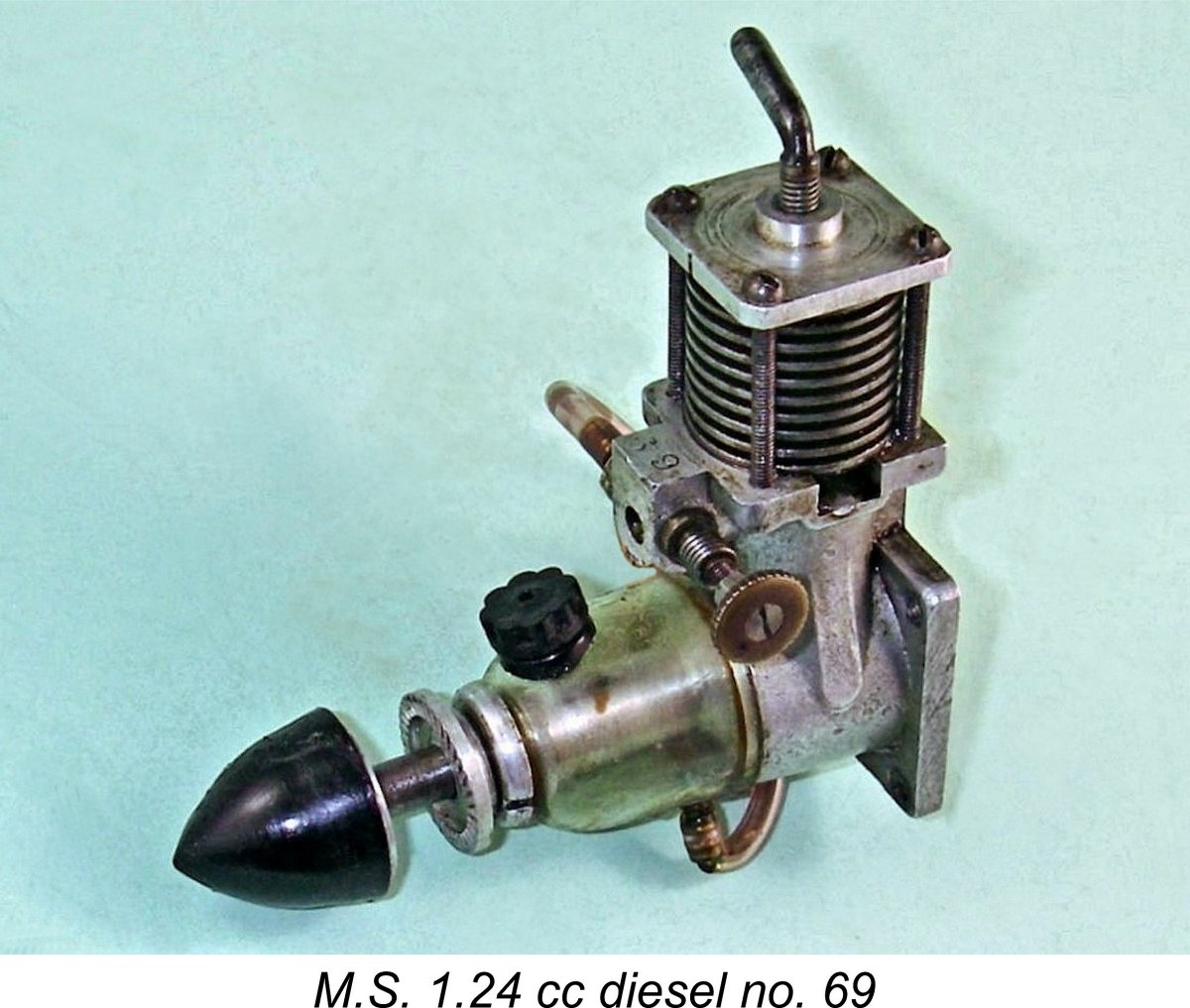 Against this, the manufacturers invariably quoted the engine’s displacement very precisely as 1.24 cc. The precision with which this figure was cited leads one to the strong suspicion that the engine’s nominal design bore and stroke dimensions were
 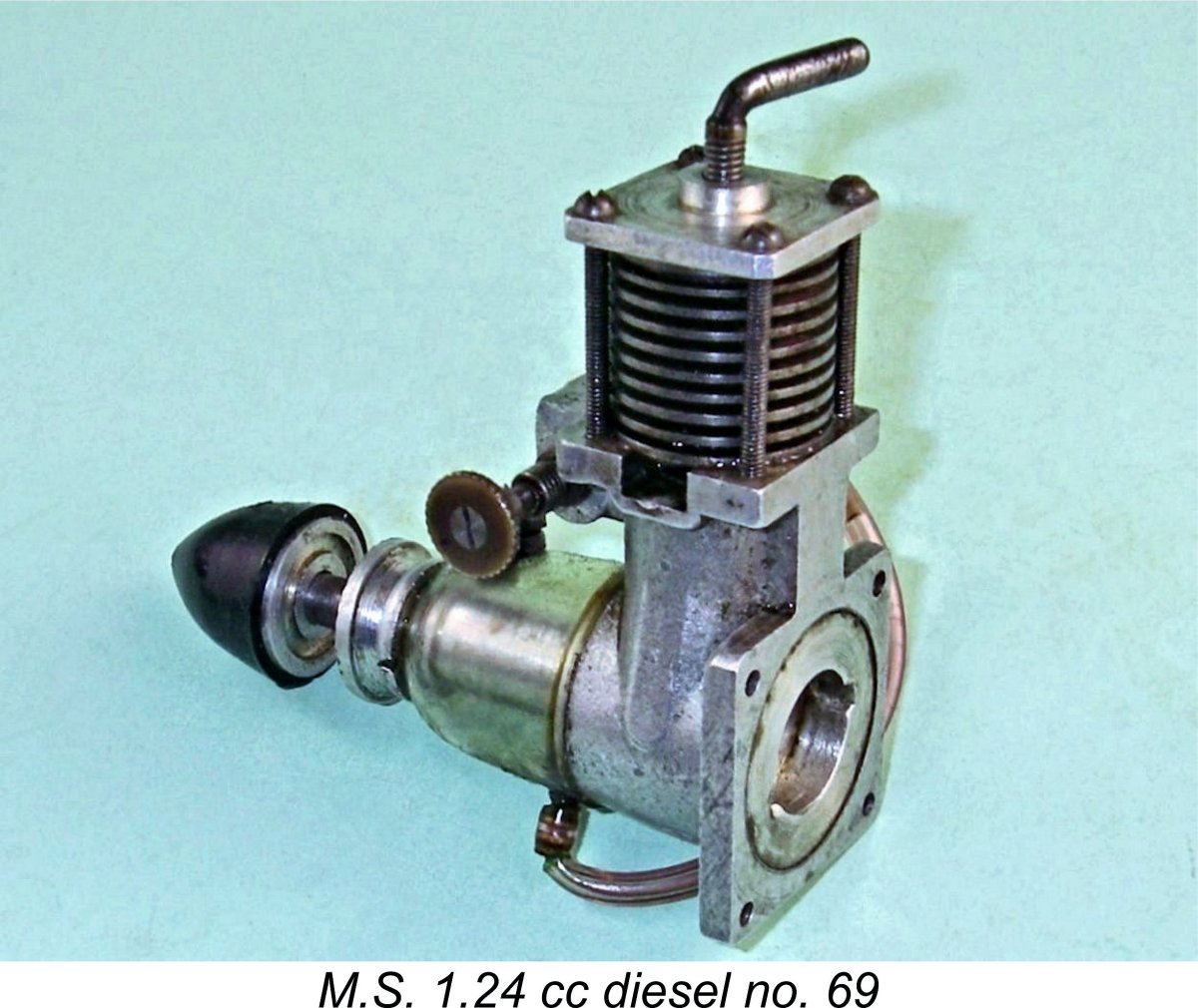 In terms of general styling, the M.S. 1.24 cc model retains the square cylinder head, sideport induction, 4-bolt cylinder attachment and radial mounting of its larger predecessor. It also appears to feature the same material specification.
 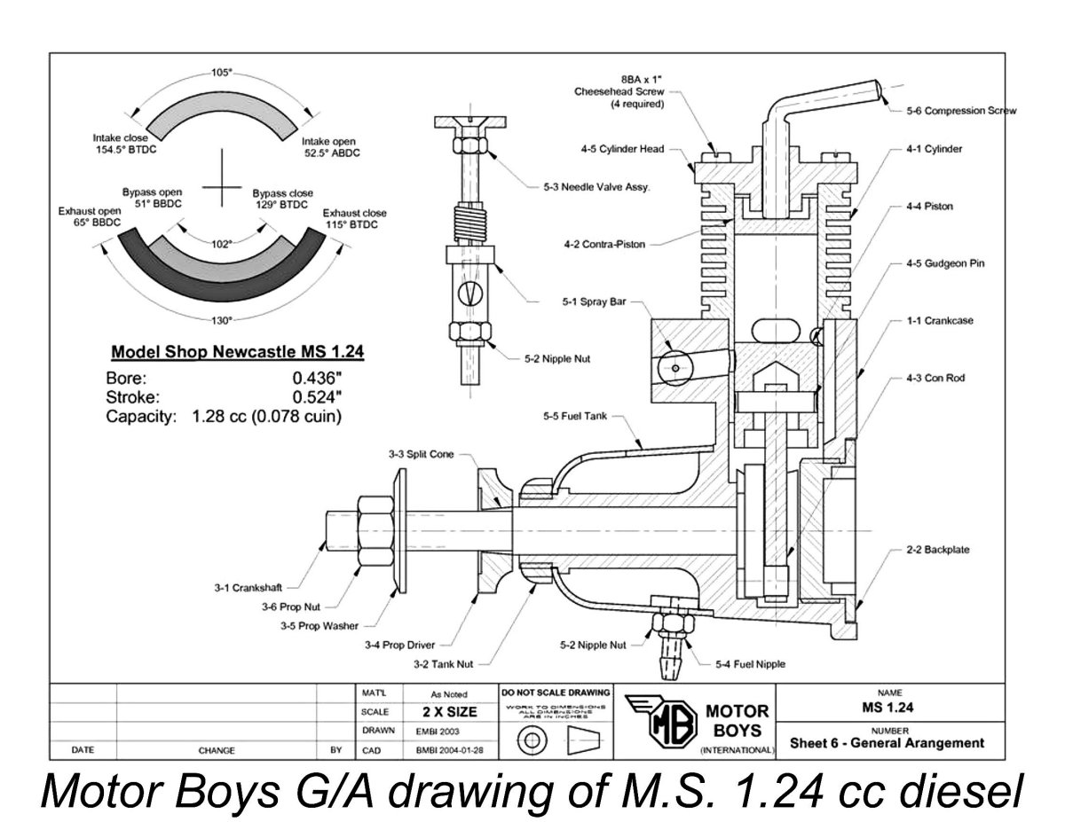 In a sideport design, a sub-piston induction period of this magnitude is highly unusual - other sideport engines incorporating this feature, such as the
 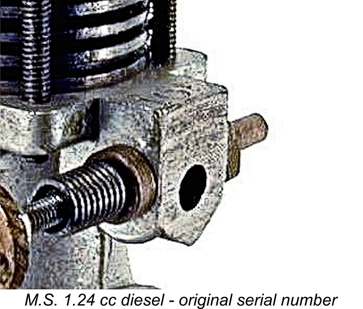 Taking advantage of the absence of any timing assembly at the front, the designer chose to mount the horizontally-oriented plastic fuel tank on the front of the M.S. 1.24 cc design, using a shelf formed on the front face of the crankcase as its locating base. The main bearing housing is externally threaded at the front to accommodate a large-diameter slotted ring-nut which secures the tank. There are certainly precedents for this arrangement, but it's far from common. That said, it seems to be perfectly functional.
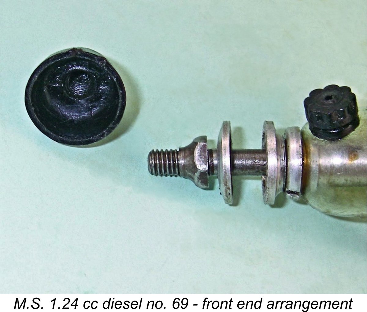
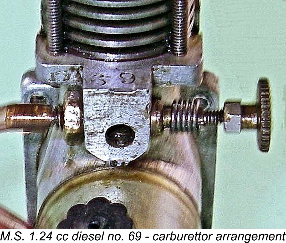 The forward-facing intake is fitted with a spraybar having an external diameter considerably in excess of the venturi throat diameter. It appears to have been installed and then drilled through in place at the same 0.130 in. (3.30 mm) diameter as the venturi throat, probably at the same work-setting. One side of the resulting transverse hole through the spraybar carries the fuel supply spigot and surface fuel jet, while the other side is internally tapped 8 BA to accommodate the externally-threaded needle.
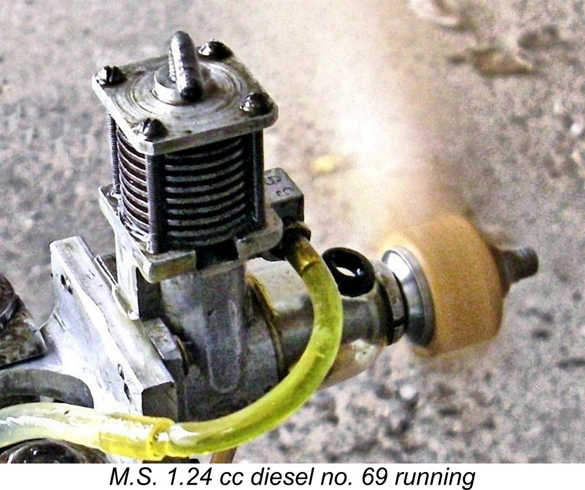 As with the larger M.S. 2.5 cc model, I had no prior information regarding the appropriate prop sizes to try. I was aware that the engine’s previous owner had run it successfully, but he had provided no prop data. Looking at the power coefficients for my collection of calibrated test props, I decided to begin with a Rev-Up 8
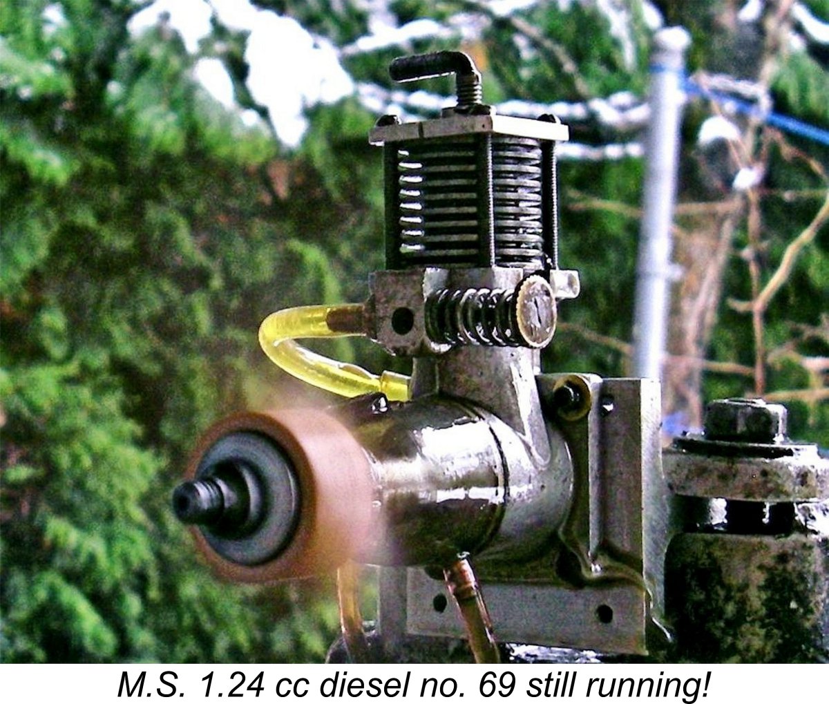
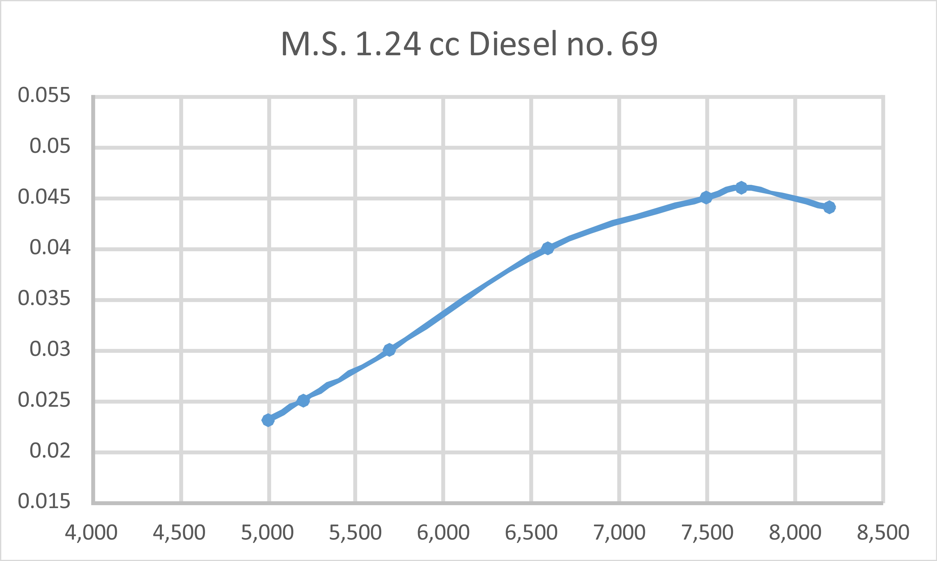
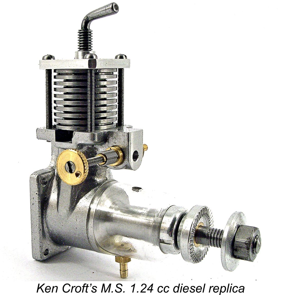 Ken took the required measurements and made a pattern to produce the necessary crankcase sand-casting. He then proceeded to make the
 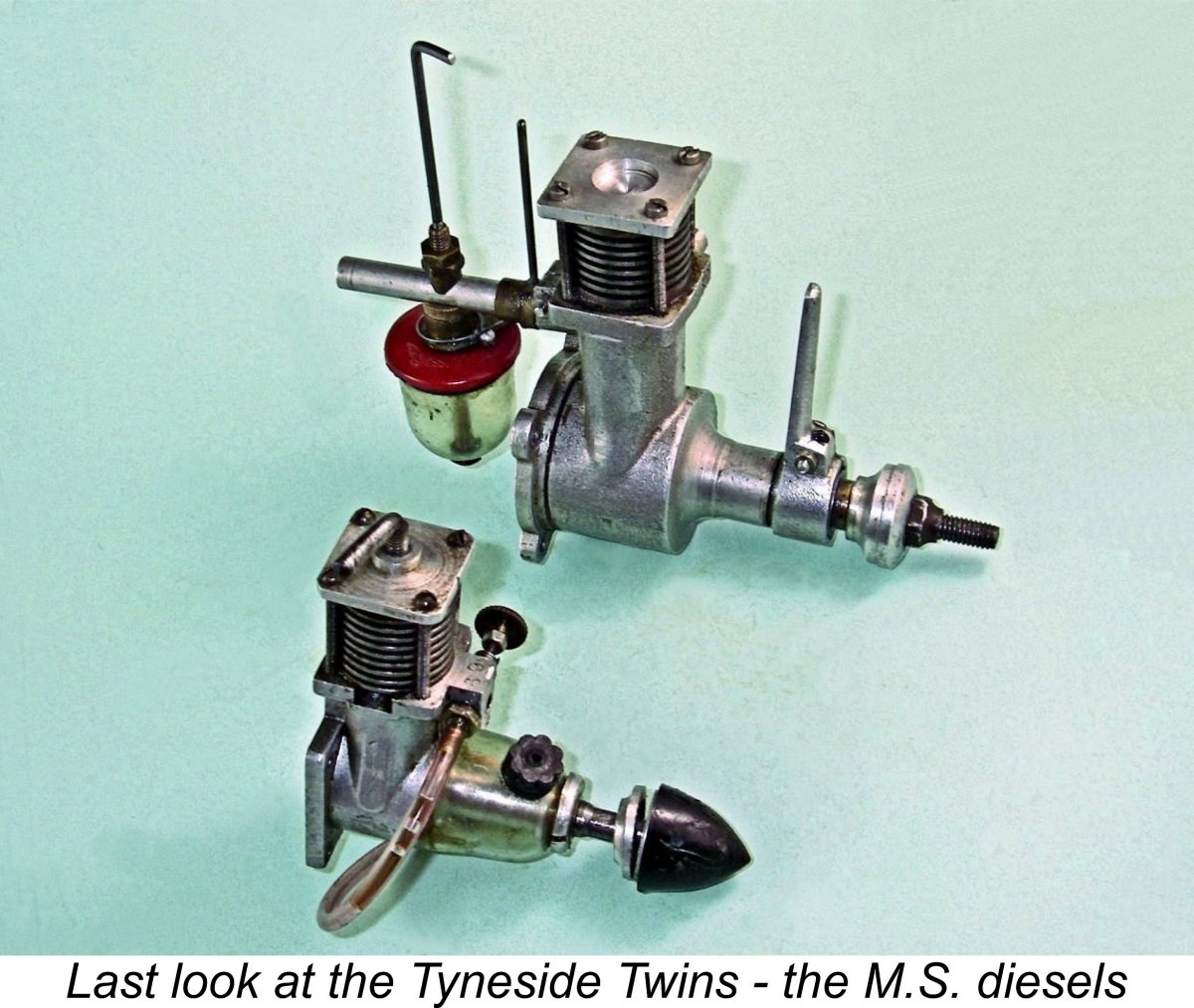 The rarity of the M.S. diesels is such that few model engine aficionados will ever see one, let alone own one. I’ve been incredibly fortunate in acquiring the matched pair featured in this article.
| |