
|
|
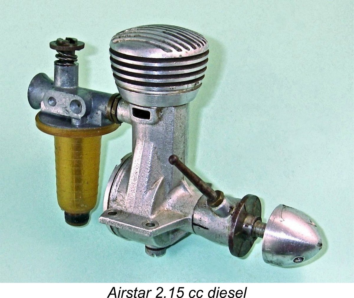
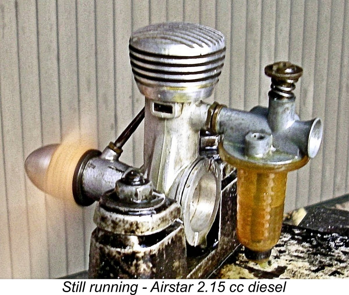
The Airstar 2.15 cc Diesel
I used the terms “enigmatic” and "ostensibly" because the true origin of this rather unusual engine has become very much obscured by the passage of time. Although it was presented as a product of a British manufacturer, the reality is that it was as much a French product as a British one. It was certainly a French design. One of my main objectives in writing this article is to set the historical record straight. Moreover, considerable confusion has arisen regarding the engine's dating. In the past, its introduction has generally been assigned to 1947, but it appears certain that this date is incorrect. I’ll devote a whole section of this article to a discussion of the dating issue. To place the Airstar story in context, we have to go all the way back to pre-WW2 France. Let’s begin by doing just that. Background
It’s a greatly under-appreciated fact that France was among the first countries in which the manufacture of model engines was put on a commercial basis. Radiguet & Massiot had set the ball rolling way back in 1911 with their opposed twin-cylinder two-stroke engine of 16 cc displacement which was specifically intended for model aircraft use. This may have been the first model aero engine to be commercially produced in France - indeed, one of the first such engines produced anywhere. Radiguet & Massiot were soon joined by the Galiment company, who introduced a series of one, two and three-cylinder four-stroke model aero engines in 1912. The Godefroy brothers soon joined in the fun, producing a very fine V-twin four-stroke model of 21 cc displacement in 1912. This design proved to be very successful. Unfortunately, at this point the major nations of Europe managed to stumble into the disastrous conflict of WW1. This naturally put an end to model engine experimentation and production for the next four years. As if this wasn’t enough, the end of the war was closely followed by the worldwide influenza epidemic which actually claimed more lives than the entire WW1 conflict. The human and economic impact of this sequence of events gave rise to conditions in which the resumption of model engine manufacture was the last thing on anyone’s mind. A very few model engines were constructed in France during the 1920’s by talented amateur enthusiasts, but for the most part these were model boat powerplants. Power aeromodelling stagnated throughout much of this period.
By 1937, conditions had improved to the point that other companies such as Train and Terrot had also commenced operation - even the prestigious Peugot automobile company joined in with a fine 10 cc model which was made in limited quantities by their trainee employees as an exercise. 1938 saw the entry into the French model engine market of an amazing number of newcomers, including Artus-Borde, Astus, CEKO, Radium, Stab and the famous R.E.A. range, of which much more elsewhere. Among those taking an interest in model engines at this time were the Paris-based Fargeas brothers Roger and Georges. They constructed their first engine in 1939, just prior to the onset of WW2. Despite the fact that Paris was occupied by the Germans for over 4 years from June 14th, 1940 to August 24th, 1944, the brothers somehow managed to find both time and opportunity during this period to construct a short series of 12 engines of 5.5 cc displacement. This highlights an unexpected and seldom-recognized aspect of the period during which France was under German occupation. This is the indisputable fact that a significant market for model engines undoubtedly continued to exist during the occupation. This market was sufficient to encourage a gentleman named J. Durandeaux to commence the marketing of engines under the Airplan name during 1941. The strength of the market was in fact sufficient to encourage others to follow suit, as witness the appearance of new designs from no fewer than eight different French manufacturers during 1943 alone.
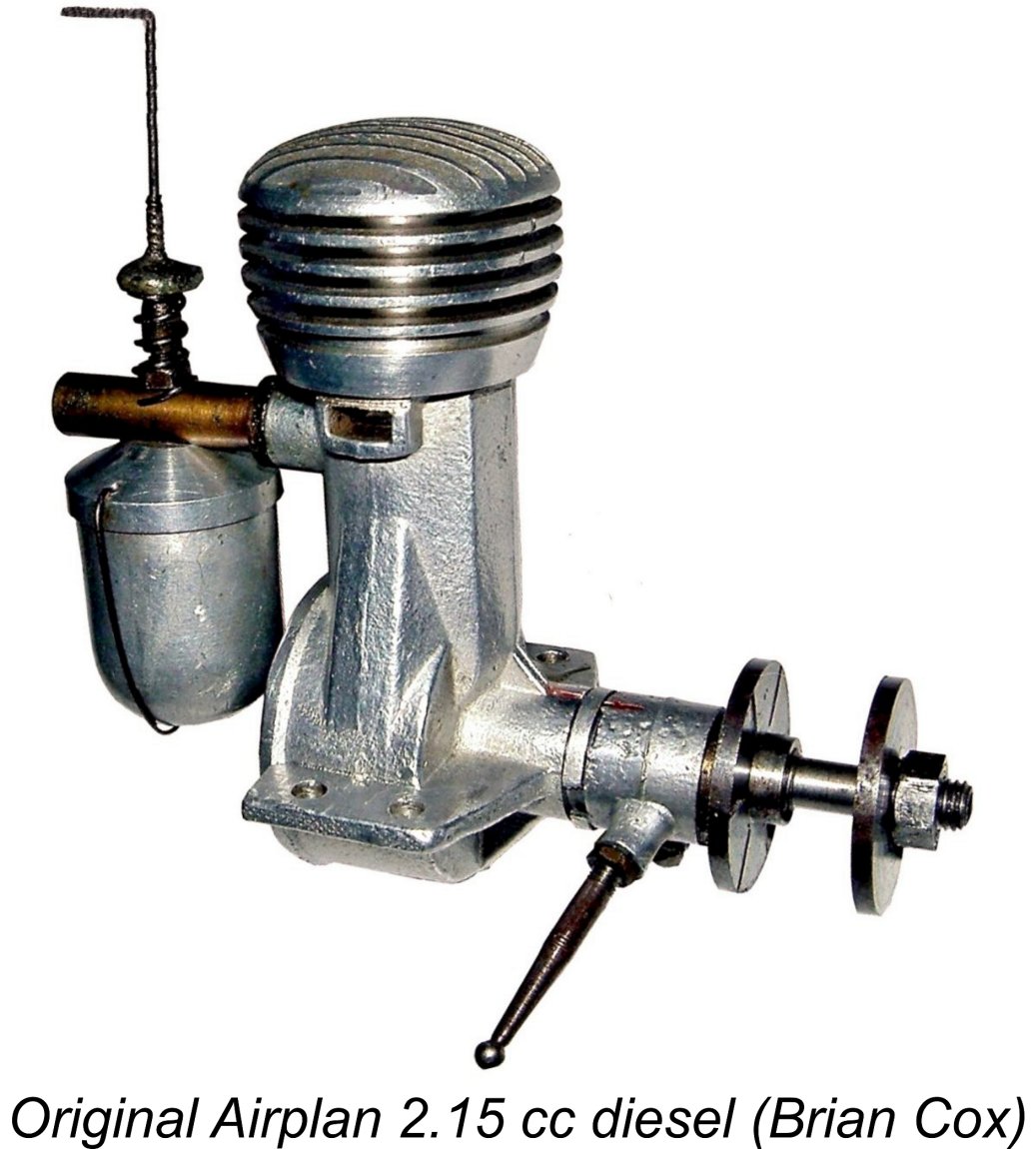
Be that as it may, the first engine offered under the Airplan name during 1941 was a 3.3 cc spark ignition model of relatively advanced design. The attached image extracted from Maeght's book shows this engine set up for inverted operation. Thereafter, development of new Airplan models appears to have stagnated for a few years, since further designs did not begin to appear until 1944, when a revised version of the 3.3 cc sparker made its debut. One interesting aspect of the Airplan venture is the fact that Durandeaux does not seem to have designed or even constructed his own engines - he simply marketed them. He traded from premises on Rue Ramus in Paris. On his business card, he styled himself as an “aviator” as opposed to a model engine manufacturer. It’s been very well established that his engines were in fact designed and constructed by individuals such as André Gladieux (later of Micron fame) and the aforementioned Roger Fargeas. Speaking of whom, by 1945 Roger Fargeas was working for the Airplan venture. He designed and produced several new models, including a 5 cc spark ignition design as well as a pair of fixed compression diesels having displacements of 2 cc and 5.5 cc. The latter unit was known as the “Normandie” model.
Accordingly, only a very few examples of the original Airplan 2.15 cc diesel were produced. The engine is consequently largely forgotten today. This particular model is not even featured in the Airplan section of Adrien Maeght’s previously-cited book on French model engines. An illustration of the Airplan 2.15 cc model does appear on page 53 of the book, but it is incorrectly labelled as a 5 cc Fargeas diesel from 1941. As I said earlier, Maeght's generally excellent book is by no means free from error. It’s interesting to note the fact that the Ouragan engines subsequently produced by the Fargeas brothers continued to feature the eccentric main bearing system of compression adjustment which had been a feature of the Airplan 2.15 cc model. Diesels having displacements of 0.9 cc and 3.36 cc were produced to a basically similar design in 1946 and 1947, after which the Ouragan range followed the Airplan series into oblivion. Now it gets really interesting! Fargeas’s departure in early 1946 left Durandeaux holding a number of unfinished examples of the new 2.15 cc model, together with an inventory of previously-manufactured components sufficient to construct a number of additional examples. Having no-one to complete the engines, he looked around for alternatives, soon making contact with the English precision engineering firm of J. P. Steward & Co., who were located in Luton, Bedfordshire but also had premises in Paris. Doubtless that was how the connection was made. The Steward company acquired the entire stocks of unfinished Airplan 2.15 cc diesel engines and components, along with the rights to the design itself.
It appears that the Steward company was able to acquire the Airplan project at a quite favourable price. It’s also readily apparent that production of the Airstar diesels was as much a simple matter of assembling pre-existing parts as it was a manufacturing process, although some components of the Airstar do seem to have been manufactured by Steward (see below). Naturally, the use of many previously-manufactured components obtained at a relatively low price greatly reduced the unit production cost of the Airstar. The purchase of the fully-developed design from Airplan also neatly sidestepped the costs normally associated with the development of an all-new design. These factors allowed the Airstar to be sold at a very competitive retail price of only £3 15s 0d (£3.75). By 1948 standards, this was a very reasonable price indeed for a diesel of this displacement - for example, the competing Allbon 2.8 cc diesel sold for £4 16s 0d (£4.80), while the 2 cc E.D. Mk. II was on offer at £4 4s 0d (£4.20).
The above train of events makes it clear that while the Airstar 2.15 cc model is generally viewed as a British product, it is actually a French design, almost certainly developed by Roger Fargeas. It also appears to have incorporated some French-made components. It thus represents a collaboration between a French designer/manufacturer and a British precision engineering firm - very much an international effort! The Airstar’s true origins have been somewhat obscured by the fact that when it appeared in England, it was presented from the outset as a British product. Its true French origins were hinted at, but not clearly stated. This obscurity has persisted down through the years. The only later reference to the Airstar’s true origin that I can find appears in O. F. W. “Peter” Fisher's well-known 1977 book “Collector’s Guide to Model Aero Engines”. Fisher mentions that the Airstar was derived from a French Airplan design, but confirmed during later discussions with my friend Brian Cox that he had never actually seen an example. The Dating Issue As stated at the outset, the date of the Airstar’s introduction to the British market has hitherto always been given as 1947. This is certainly consistent with the early 1946 date at which production of the original Airplan offering was initiated before the departure of Roger Fargeas to establish his own Ouragan model engine marque later in 1946.
Firstly, the Airstar is not featured in D. J. Laidlaw-Dickson’s pioneering book “Model Diesels”. This is hardly surprising since that book was published in late 1946, before the transfer of the Airplan assets to Steward & Co. More significance may be attached to the fact that the engine also escaped notice in the first edition of Col. C. E. Bowden’s book “Diesel Model Engines” despite the inclusion of a number of even more obscure designs of the period. Col. Bowden’s first edition was published in the latter part of 1947, suggesting very strongly that the Airstar had yet to appear at that time. Another indication is provided by the quite comprehensive listing of then-current British model diesels published by Henry J. Nicholls in his advertising placement which appeared in the February 1948 issue of “Aeromodeller” magazine. This placement is reproduced at the right. Although essentially all then-current British model diesels of any note were included, there was no mention of the Airstar. If the engine was in existence at that time, it’s very unlikely to have escaped Nicholls’ notice. Perhaps even more significantly, there’s also no mention of the Airstar in the article by D. J. Laidlaw-Dickson entitled “British Commercial Diesel Engines - Spring 1948” which appeared in the March/April issue of ”Model Mechanic” magazine. If the engine had in fact been introduced in 1947, it’s very difficult to believe that it would not have been included in that unusually comprehensive article - My good mate Maris Dislers was kind enough to troll through his collection of "Aeromodeller" and "Model Aircraft" magazines of the period. The first reference of any kind to the Airstar 2.15 cc diesel that Maris was able to find was an advertising placement which appeared in the October 1948 issue of "Model Aircraft". This advertisement (reproduced at the left) was placed by J. P. Steward & Co. Ltd., who were identified as the "manufacturers". The engines were said to be distributed by a firm called Signalling Equipment Ltd. of Potters Bar, Middlesex. The wording of the advertisement makes it quite clear that this was an introductory placement, referring as it did to the engine being "now available". In my book, this one advertisement pretty much settles the dating question. Allowing for Editorial lead time, it clearly implies that the Airstar first reached the market no earlier than August 1948. Further confirmation of this dating was supplied by my valued French colleague Michel Rosanoff of "Retroplane Forum" fame who advised that at around the same time in 1948 a Paris firm named TRANSIMEX of 1 Cité Bergère, Paris 9 was appointed as the official French distributor for the Airstar diesel. Their first advertisement appeared in the magazine "Modéle Réduit d'Avion" issue number 116, October 1948. It's clear however that this association didn't last long, because Michel reports that there were no further advertisements. Michel also recalled a write-up on the Airstar which appeared in the May 1968 issue of the Belgian magazine "MODEL AVIA". That article recorded the fact that a company called Cogéa was appointed as the official distributor of the Airstar in Belgium. Interestingly enough, that company was mainly involved with full-sized aviation! Among other activities, they owned and operated the Keerbergen Airport, a small airport located some 28 km northeast of Brussels. .It's unclear how their appointment as Airstar distributors came about. Apart from the above cross-Channel marketing initiatives, it appears that the introduction of the Airstar attracted the immediate attention of at least one British retailer, because Maris Dislers also found an advertisement placed in "Aeromodeller" magazine by the well-known Cardiff model retailer and early mail order specialist Bud Morgan in the same month of October, 1948 which specifically mentioned the Airstar. The same firm advertised the engine once more in their placement in the February 1949 issue of the same magazine.
As far as I can determine from a search of my own incomplete magazine collection, the last Airstar advertisement of them all was a March 1949 placement by the manufacturers in "Model Aircraft" magazine. This was a duplicate of the previously reproduced advertisement of October 1948. The Airstar thus had an advertising life of some 6 months, indicative of the engine's failure to make any real impression upon the British market despite a seemingly energetic promotional effort. The first non-advertising appearance of the Airstar in the contemporary modelling media is to be found in Ron Warring’s book “Miniature Aero Motors”. Although the Airstar was not specifically discussed in the text, Warring did include three images of the engine which yielded valuable information. He also included a few technical details of the Airstar in Appendix II. This book was published in January 1949, but there’s a great deal of internal evidence to suggest that the technical tables which make up Appendix II were compiled by late 1948. The Airstar is listed in Warring’s table as being in current production, which is completely consistent with the September 1948 introductory date suggested by the advertising. The Airstar finally made its one and only contemporary "starring" media appearance in the 1949 revised second edition of Col. Bowden’s previously-cited book. In that work, the gallant colonel referred to the Airstar as a “new” product, an unlikely term to use in 1949 for an engine which had actually appeared back in 1947! Bowden devoted over a page to the engine, including an illustration. His defining comment read: “A most interesting engine …… my Airstar is a good starter and a reliable performer”. An objective review of the considerable body of evidence summarized above pretty much confirms that the Airstar was actually introduced in around August 1948 rather than at some point during 1947. It would seem that an unknown earlier commentator assigned the 1947 date on some unsubstantiated basis, and that subsequent commentators have fallen into the all-too-common trap of simply accepting this date as gospel without checking the evidence, of which there’s plenty. This dating raises the question of why it took Steward & Co. over 21/2 years to attempt to cash in on their early 1946 purchase, which was the result of delaying the release of the Airstar until August 1948. I can only suggest that they had plenty of other work to keep them occupied, only pursuing the development of the new dies and different tooling required to construct their rendition of the engine as and when time permitted. A bit of a mystery, to which we'll never know the answer. Now that we’ve hopefully clarified the rather unusual origins of the Airstar 2.15 cc diesel as well as its dating, it’s time to begin our look at the engine itself. As a first step, it’s worth spending some time describing the operation of the eccentric bearing system of compression adjustment. The unfamiliarity of the system to many present-day readers pretty much requires this. In addition, there are far more subtleties involved than most folks realize, even among those who think that they understand the system! That having been said, those who feel that they are already sufficiently familiar with this arrangement are advised to proceed directly to the later sections of this article. The Eccentric Bearing Compression Adjustment System.
In the system now under discussion, this arrangement is effectively reversed. The principle is of course the same, but the head stays fixed and it’s the elevation of the working piston at top dead centre that is varied to achieve the same alteration of the combustion chamber volume at top dead centre. The operating principle is identical - only the means of achieving it are different. In this configuration, the main bearing is equipped with a bronze bushing inserted into the crankcase's main bearing housing. This serves as the bearing shell which supports the main crankshaft journal. So far, so familiar, but with this system the bushing is internally bored eccentrically (off centre) rather than centrally as in the usual case.
Such designs invariably include a long control arm located at the front of the bearing, as seen on the M.S. 2.5 cc diesel depicted at the right. This arm is secured to the internal bushing either by clamping or through some mechanical connection, constraining the bushing to rotate in the case as the arm is moved. Since the actual bearing itself is reamed eccentrically in the bushing, the effect of turning the bushing in the main bearing casting is to raise or lower the crankshaft relative to the rest of the engine, in particular the fixed cylinder head. This in turn raises or lowers the working compression ratio by altering the elevation of the piston crown relative to the cylinder head at top dead centre. In effect, the working piston does double duty as both the power and contra pistons, using the conrod as the compression screw! The beauty of the eccentric bearing system for a diesel engine aimed at a mid to late 1940’s marketplace which was still accustomed to spark ignition operation is of course that the compression control arm functions exactly like the timer arm of a spark ignition unit by controlling the ignition timing. Operation of Another advantage of the eccentric bearing compression adjustment system is that the engine can be made considerably less "tall" than it would be with a conventional comp screw/contra piston arrangement. Both the Gamages advertising and the commentary by Col. Bowden highlighted this advantage in the case of the Airstar. Indeed, the engine is remarkably squat, especially considering the fact that it is an exaggeratedly long-stroke design. The attached image showing the Airstar in company with an Italian MOVO D-2 of slightly shorter stroke (18 mm) and lesser displacement should serve to highlight this point. A major downside of the system is that adjustment of the compression ratio in this way also has the effect of altering the cylinder port timing. This is why I have refrained from giving any timing figures for this engine - they are highly variable! Since the Another often-overlooked factor which will inevitably be affected by the application of eccentric-bearing compression adjustment is the lateral alignment of the crankshaft centre line relative to the cylinder axis. Engines featuring some degree of lateral crankshaft offset from the cylinder axis are known as Desaxe designs. Contrary to a seemingly widespread belief, the name is not derived from that of its inventor but rather from the French word “désaxé”, which means “off centre”. The advantages of a Desaxe layout arise from the fact that by moving the shaft centre-line towards the compression-stroke side of the engine (the left side looking forwards in a model engine designed for normal rotation), the rod swing angle on the power stroke can be appreciably decreased. This results in an increase in the leverage applied by the piston to the crankpin on the power stroke, together with concurrently reduced piston side-thrust and associated friction losses. It also promotes a measure of additional piston “dwell” at the top of the stroke, which can offer combustion benefits in addition to lengthening the angular duration of the power stroke by comparison with the compression stroke.
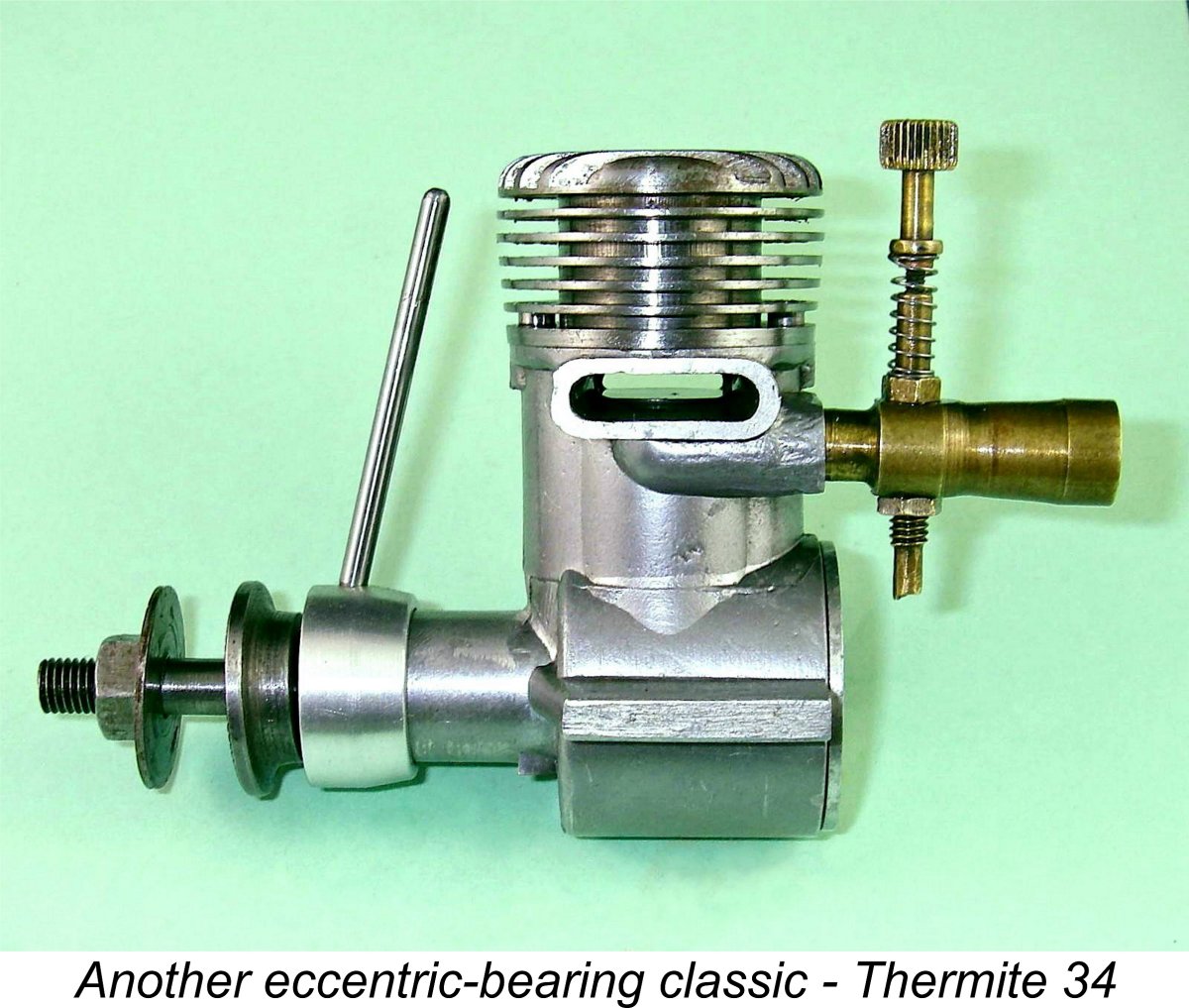
If you’ve followed the above comments, it should be readily apparent that the rotation of an eccentrically-bored main bearing sleeve will change not only the crankshaft elevation relative to the cylinder head but also the degree to which the crankshaft is laterally displaced from the cylinder axis. Hence changes in compression ratio have the potential to affect the degree to which the engine incorporates the Desaxe arrangement. The attached image showing the Thermite 34's bushing in Desaxe orientation should help to make this clear. To take best advantage of the Desaxe effect, the bushing on an eccentric-bearing compression ignition engine having a centrally-bored main bearing housing should ideally be positioned with the actual bearing bore offset towards the compression stroke side, that is, towards the rear-view left-hand side of an engine intended for normal rotation. Another advantage of this configuration would be that any tendency of the bushing to rotate with the shaft due to main journal friction will be resisted by the counter-rotational couple created by conrod pressure acting upon the offset shaft. The one potential problem with this approach is that the compression lever will then function in the opposite direction to the timer arm of a spark-ignition engine - to increase compression, thus advancing the ignition timing, one has to rotate the bushing in the direction of normal engine rotation. Considerations of operational familiarity for spark ignition users might suggest that the bushing should actually be fitted with the bearing offset to the right, which will give the reverse of the ideal Desaxe geometry but will make the compression arm operate in exactly the same manner as a spark ignition timer arm - increased compression and hence more advanced ignition timing will result from rotating the bushing in the opposite direction to normal engine rotation. However, one soon gets used to the alternative mode of operation. Another potential problem with setting the engine up to operate in this way is that fact that if the resistance of the system to friction-related bushing rotation is overcome for any reason, the consequent "creep" of the bushing in the running direction will increase compression. This will give rise to elevated mechanical stresses within the motor, eventually causing it to labor to a halt. Not good for longevity or structural integrity ……… A further issue arising in connection with this design is its vulnerability to crash damage. The location of the compression arm at the very front of the engine (and hence the model) is tailor-made to expose it or its mounting to breakage in a crash of even modest proportions.
All of the images included in Ron Warring's previously-cited book show the Airstar fitted with a flywheel for use in in boat or car applications. It thus appears that such uses were envisioned by the manufacturers. In such a case, it would be necessary to accommodate the variable alignment of the shaft relative to the model through the use of a double universal arrangement. Despite the various issues discussed above, operating experience with several different designs using this form of compression adjustment has demonstrated to my own complete satisfaction that the system works very well indeed. The arrangement most likely fell out of use due to a combination of its greater complexity, higher manufacturing cost and vulnerability to crash damage - indeed, Laidlaw-Dickson actually commented upon the system very much along these lines. Now, having described its unusual compression adjustment system, it’s time to proceed to a general description of the Airstar engine itself. As we'll see, this is very far from being just another conventional sideport diesel! The Airstar 2.15 cc Diesel - Description
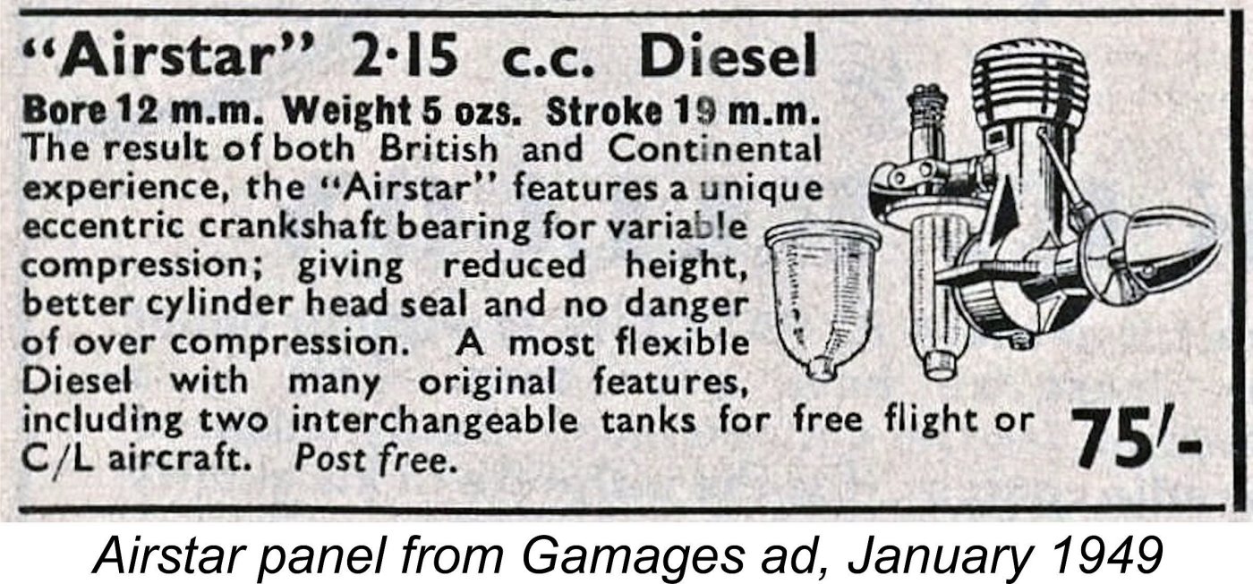
The engine’s weight is cited as 5.0 ounces (142 gm) precisely. All of these figures conform to those given in the advertising. My illustrated example weighs in at 144 gm - near enough to the advertised figure. The Airstar diesel displays a number of design concepts which set it well apart from the general run of model engine designs of its day. Its cylinder porting is quite conventional for a sideport diesel, but the adherence to convention pretty much stops there. To begin with, no bolts or screws are used in the engine’s construction. The use of the eccentric bearing system for compression control also means that there’s no contra-piston. The hardened 3% nickel steel cylinder liner is bored right through, hence having to be sealed by the screw-on cooling jacket which thus serves as the cylinder head. The liner's lower section is a fairly tight push-fit in the upper crankcase. The really interesting aspect of this assembly is the manner in which a head seal is achieved. We might expect that the head would seal itself against the top of the liner with an interposing gasket. However, this would result in the transmission of the very considerable force needed to ensure a good seal down through the entire working length of the liner, raising a strong possibility of distortion.
This arrangement has the highly desirable effect of eliminating any cylinder hold-down forces from within the cylinder liner itself - all such forces are absorbed by the flange, which is sandwiched between the upper crankcase and the cooling jacket. The interface between the flange and the jacket serves as the actual head seal As a result, the gas-tight junction between the jacket and the cylinder is located half-way down the external cylinder wall at the base of the cooling jacket rather than in its usual location at the top of the liner. A very unusual arrangement …… but why not?!? A nice example of thinking outside the box! Gas pressure is thus free to act upon both inside and outside portions of the upper cylinder wall above the flange, although the very close push fit between the jacket I/D and the cylinder liner O/D means that the arrangement adds essentially no additional volume to the combustion chamber. Once oil is introduced into the assembly, the very small clearance between the upper cylinder’s outer wall and the inner surface of the cooling jacket will fill with oil and the head seal will be about as good as it can get! The other effect of this system is that the alignment of the fore-and-aft cylinder head fins is totally dependent on the shimming effect provided by the fibre gasket(s) used between the upper surface of the cylinder flange and the lower surface of the cooling jacket. It seems that the alignment was achieved by selectively fitting one or more of those gaskets until the top fins aligned correctly when everything was securely tightened down with the engine warm. My own well-aligned example has two such gaskets, but more or fewer could be used if necessary to align things correctly.
I was not able to expose the conrod, but the manufacturer's own specifications (see below) confirm that the rod was machined from case-hardened 3% nickel steel. The use of hardened steel for this component was a quite common choice during the late 1940’s. A conventional gudgeon pin was used at the small end. The hardened 3% nickel steel crankshaft was carried in an eccentrically-bored sleeve which was machined from gunmetal (a form of bronze). One of the images in Warring's previously-cited book shows the engine partially disassembled. From this image, it's possible to see that the crankweb was quite heavily counterbalanced. At the front of the main bearing, the compression adjustment system consists of a cast alloy collar which is mounted on an external cylindrical bearing formed on the outside of the main bearing housing. This collar is provided with a protruding internally-threaded spigot which accommodates the screw-in steel timer arm, using which the collar can be rotated on its bearing. The collar is securely connected to the internal eccentric bronze bearing such that the collar and the bearing are constrained to turn as one. The original Airplan design featured a collar which was tensioned against its bearing by means of a horizontal split which could be tightened around the bearing to the extent necessary by means of a clamp screw. This provided the tension necessary to prevent friction-induced rotation of the collar in the direction of engine operation, with a consequent unplanned change in the compression setting. A cut-away at the front of the collar engaged with a screw threaded radially into the moveable eccentric bronze bearing, thus constraining the eccentric bearing to turn with the timer arm.
The collar is connected to the main bearing sleeve by a steel stake, the outer end of which is clearly visible just behind the prop driver in the accompanying image. One would suspect that the inner sleeve would be provided with a narrow slot with which the protruding inner end of the stake engaged. Only in this way would it be possible to provide for the removal of the collar for re-tightening of the three-way split or dismantling of the engine - once installed, the steel stake is definitely not removable. However, examination of the bearing following removal of the prop driver reveals that no such slot is present. The collar is thus permanently staked to the inner bearing sleeve. This appeared to me to represent a major design flaw, since it would seem impossible to remove the collar to tighten its clamp section, nor could the main bearing sleeve be removed if replacement became necessary.
An aluminium alloy spinner nut is used to secure the prop. This is threaded M5x0.75, reflecting the likely French origins of these components. The prop driver is of steel. My initial attempts to remove the prop driver were unsuccessful - since I had assumed that it was mounted on a taper of some kind, I had tried in vain to pull it off. Eventually I stumbled upon the fact that it is actually mounted on a coarse left-hand thread forward of the main journal - no wonder I couldn't shift it by pulling! Once I had the prop driver off the second example, I returned to thinking about the seemingly impossible maintenance issue created by the permanent staking of the compression adjusting collar to the eccentric bearing sleeve. I reasoned that a designer of the calibre of Roger Fargeas would never have developed a design with a shortcoming of this magnitude. If the control unit and attached sleeve couldn't be withdrawn towards the rear, it followed that they had to be removable from the front! Following this reasoning, I started to pull the control collar forwards. Bingo! Although a fairly tight push fit (as it has to be), the collar and attached bearing sleeve could indeed be moved forward. Not wishing to risk any deterioration, I stopped well short of full withdrawal, but this is undoubtedly how the engine is designed - to re-tension the clamping collar, one withdraws the sleeve assembly from the front in order to make the adjustment. The thrust is clearly absorbed by a shelf of crankcase material standing proud of the rear end of the bearing sleeve.
The rear of the crankcase is conventionally sealed with a screw-in backplate. This carries the stamped-on identification AIRSTAR in an anti-clockwise circular arrangement, as shown above. Unfortunately, I was unable to loosen this component using "fair" means. The carburettor of the original Airplan offering appears to have been a very conventional design featuring a straight metal intake tube along with a conventional needle valve. The spraybar also served as the bolt to retain the separate tank top, to which the metal tank itself was secured by a spring clip. Hopefully the attached image will make this clear.
The delivery end of the intake engages with a brass collet. Interestingly enough, the intake end of this collet is not threaded - instead, the fuel supply assembly is a tight push-fit onto the plain cylindrical rear section of the collet. This allows the tank to be easily oriented in any desired manner to suit different mounting situations. I suspect that the brass collet is actually the original Airplan intake tube which has been shortened to accommodate the revised carburettor casting. The collet is threaded into an induction spigot formed in the main crankcase casting at the rear, where it is secured using a lock-nut. The use of the separate brass collet is a positive measure in that any impact on the tank assembly is likely to break the collet rather than the castings. Replacement of the collet would be both simple and inexpensive.
Here we need to deal with a common misconception which has somehow become entrenched. It has generally been stated in the past that there were two versions of this engine - the control-line model and the free flight variant. In fact, only one version of the Airstar was ever sold. The confusion has arisen because each individual engine was supplied new with both large and small tanks. Most examples encountered today have one tank or the other fitted and have become separated from the alternative tanks with which they were supplied by the manufacturer. Examples fitted with the large tank are often referred to today as the “control line” version, although as we've seen only one version of the engine was ever sold in reality. There weren't two versions of the engine - there were only two distinct tanks. The larger tank was intended to serve as a general-purpose fuel container suitable for “long-run” applications such as boats and cars as well as control line aircraft. The smaller tank (like that on my own illustrated example) was specifically intended for free flight aero applications. It was provided with a series of fuel level graduation markings to facilitate the timing of the engine run - a thoughtful touch. These markings are clearly visible in a number of the accompanying images. Both tanks with which the Airstar may be encountered are also almost certainly products of the Steward company. Apart from the very different carburettor unit described earlier, the tank design itself is very different to that of the metal components used on the Airplan engines, as the images of that model reproduced earlier will have demonstrated.
The visible mixture control may look like a conventional needle valve, but in reality it’s merely a screw-in plug that protrudes to a variable degree into the venturi throat on the intake side (i.e., upstream) of the fuel jet. The manufacturers called this component an "air throttle screw". Tension is provided through the use of a coil spring. Mixture control is effected by varying the cross-sectional area of the venturi throat at that point, thus changing the negative manifold pressure at the fuel jet as well as adjusting the flow of air admitted. Again, there's more than one way to skin a cat! According to Col. C. E. Bowden, writing in 1949, the system worked well in practise. We'll see ..........
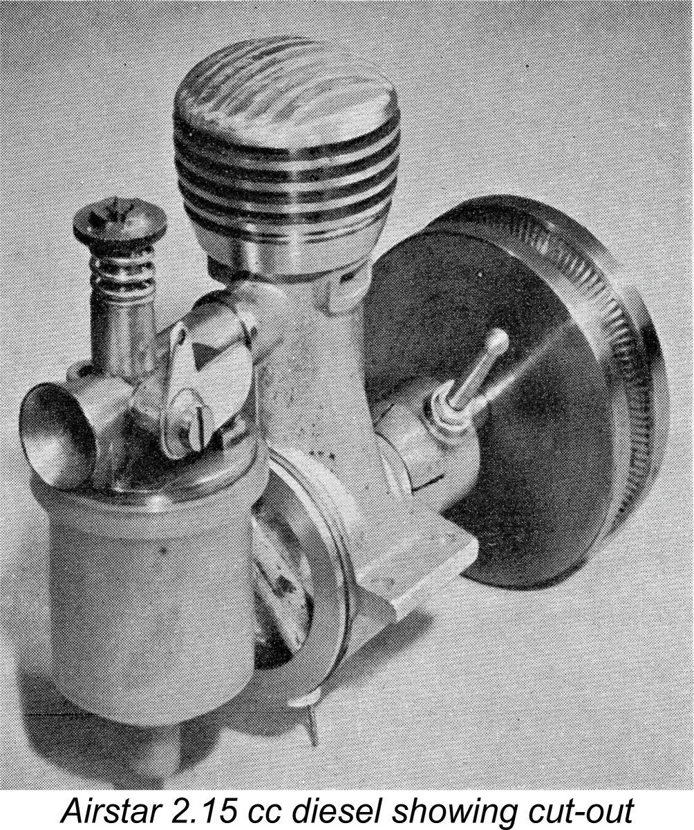
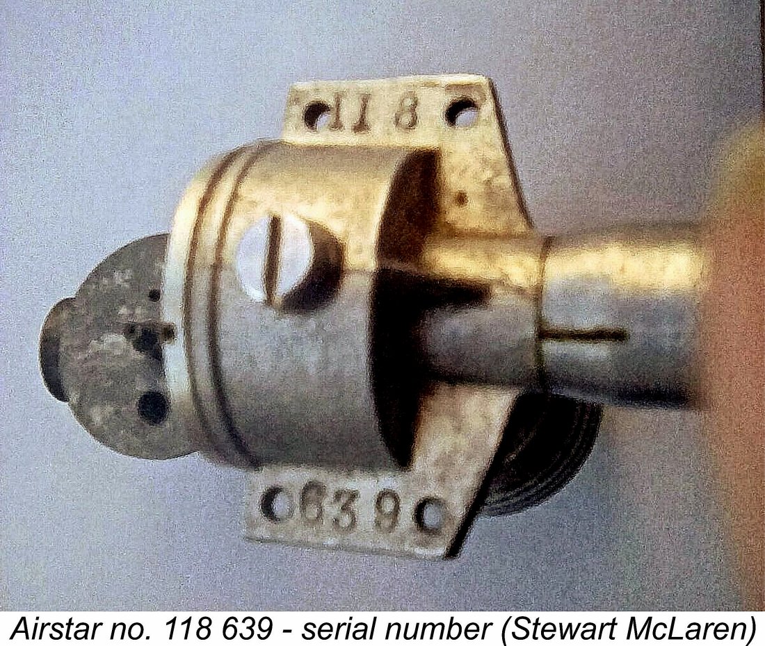
One feature of the intake casting which had me well and truly puzzled for a while was the presence of a substantial integrally-cast flat-faced "expansion" on the right-hand side of the intake tube. This expansion has two conical blind depressions formed on its surface. Hopefully the attached illustration will clarify this description. Upon first examining my example of the Airstar, I was really stumped regarding the purpose of this feature until Maris Dislers came up with the October 1948 "Model Aircraft" advertisement reproduced earlier. The illustration included in that advertisement showed that the expansion was Confirmation was quickly obtained through a re-examination of the illustrations in Ron Warring's previously-cited book. One of those images which is reproduced at the left shows a flywheel-equipped example of the Airstar which is fitted with this cut-out. Warring's associated caption specifically mentions this feature. To install the cut-out, the larger depression at the delivery end of the intake towards the front was drilled right through into the inlet tract, while the rearward depression was drilled and tapped for a pivot screw. The actual cut-out was a pivoting bell-crank flap rather reminiscent of the exhaust flaps used on R/C engines during the 1960's. When the vertical bell-crank arm was pulled towards the rear by some kind of timer device, the flap was raised, uncovering the large hole which communicated directly with the intake passage downstreal of the fuel jet. This would have destroyed all suction, stopping the engine immediately. Although the manufacturer's adverising stated that this feature could be supplied to order, it's apparent that there were few takers. I have never encountered an example of the Airstar which included this feature, either in the metal or through reports from other owners. In fact, I believe that mine is the first My example bears no serial number, although most units apparently do carry such numbers. Reader Stewart McLaren reported that his own example bears the figures II 8 stamped beneath the right-hand lug (looking forward in the direction of flight) and the number 639 stamped under the left-hand lug. I was also made aware of another example displaying the characters I 6 and 602 respectively. The significance of these numbers is presently unknown. Reader Per Byrgren of Denmark offered a speculative but seemingly logical reading of these figures. He suggested that the I and II must be either batch indicators or some kind of model identification. Since we know that examples of the Airstar were sold fully equipped for aero or car/boat use, it's equally possible that the manufacturer used Roman numerals to differentiate between aero and car/boat models. Perhaps I indicated an aero unit while II denoted a car/boat model. This still leaves the meaning of the associated numbers up in the air - perhaps batch numbers?!? Some more numbers would really help to resolve this issue! As far as the 602 and 639 go, the implication of those numbers could be read in several ways. I suspect that only a few hundred examples were made in total – I very much doubt that as many as 639 examples were ever produced. To me it seems likely that the sequence started at 500 and went up from there - a common ploy among model engine manufacturers to inflate perceived sales figures. In the absence of a meaningful serial number database, it’s impossible to draw any defensible conclusions on this issue or indeed to present any reasonable estimate regarding the number of these engines produced. All that can be said is that the number cannot have been large - the engine is extremely rare today. If anyone out there can add to our present serial number database, please get in touch! The Airstar According to the Manufacturer
Reading in my March 2021 Editiorial that I was planning to present this review of the engine in these pages, Stewart very kindly sent me some excellent scans of the instruction leaflet for the engine which he still retained. This leaflet is of considerable importance, since it provides documentary confirmation of a number of the points discussed earlier. For one thing, the leaflet confirms the International origins of the engine, which the manufacturers clearly took no pains to hide. The Airstar was said to be "the result of intensive research in the design and manufacture in our Factories in Paris and Luton, and therefore embodies the best of both Continental and British ideas and engineering practise". This represented an open acknowledgment of the major French contribution to the design. The specifications which form part of this leaflet confirm the previously-cited schedule of materials The leaflet made much of the eccentric bearing compression adjustment system, citing its major advantages as being the reduction in height of the engine, the prevention of over-compression and the elimination of the contra piston with its potential for leakage or sticking. Finally, the leaflet clarifies the manufacturer's fuel and airscrew recommendations. The suggested fuel mixture was a blend of 60% ether, 25% Castrol XL (SAE 30) mineral oil and 15% kerosene. This is pretty much a typical fixed compression diesel mixture of the day - a Drone diesel would run very well on such a brew. As far as airscrews go, the recommended size for general use was a 10x6½. The claim was made that all engines were tested and partially run in at the factory prior to shipment. A test card was apparently supplied with each unit recording the required opening of the "air throttle screw" and the position of the compression adjustment arm for starting. A full set of starting instructions were also included. A nice touch was the inclusion of a length of fine wire of suitable size to clean the fuel jet if required. The Airstar 2.15 cc Diesel on Test I was greatly encouraged in my plan to test this engine by viewing Brian Cox’s fine video of his example of the Airstar starting and running very nicely. Brian stated that the prop used in this video was a 10x6 Top Flite wood item. The engine turned this prop at a speed which produced a slightly sharp F# note, equivalent to around 5,500 rpm. This looked as if the 10x6 would be the right prop for me to begin with. Indeed, Appendix II of Ron Warring’s previously-cited book states that a 10x6 prop was the recommended size for free flight operation - not too far adrift of the manufacturer's previously-noted recommendation. For control line applications, an 8x8 was suggested. Combined with Brian’s video documentation, these recommendations provided a good basis for the selection of a suitable suite of props to use for this test. With its 10x6 Top Flite Power Point wood prop fitted, the Airstar felt really good when set up in the test stand. In keeping with my usual approach to sideport engines of its era, I gave it a couple of choked flicks and then went for a start. No reaction, even with the compression cranked up a fair bit. Clearly the fuel was having trouble finding its way up from the crankcase into the cylinder - a common situation with long-stroke sideport diesels. I then added a small prime and got an immediate firing burst, but the engine instantly flooded to a stop - too much fuel pooled in the crankcase!
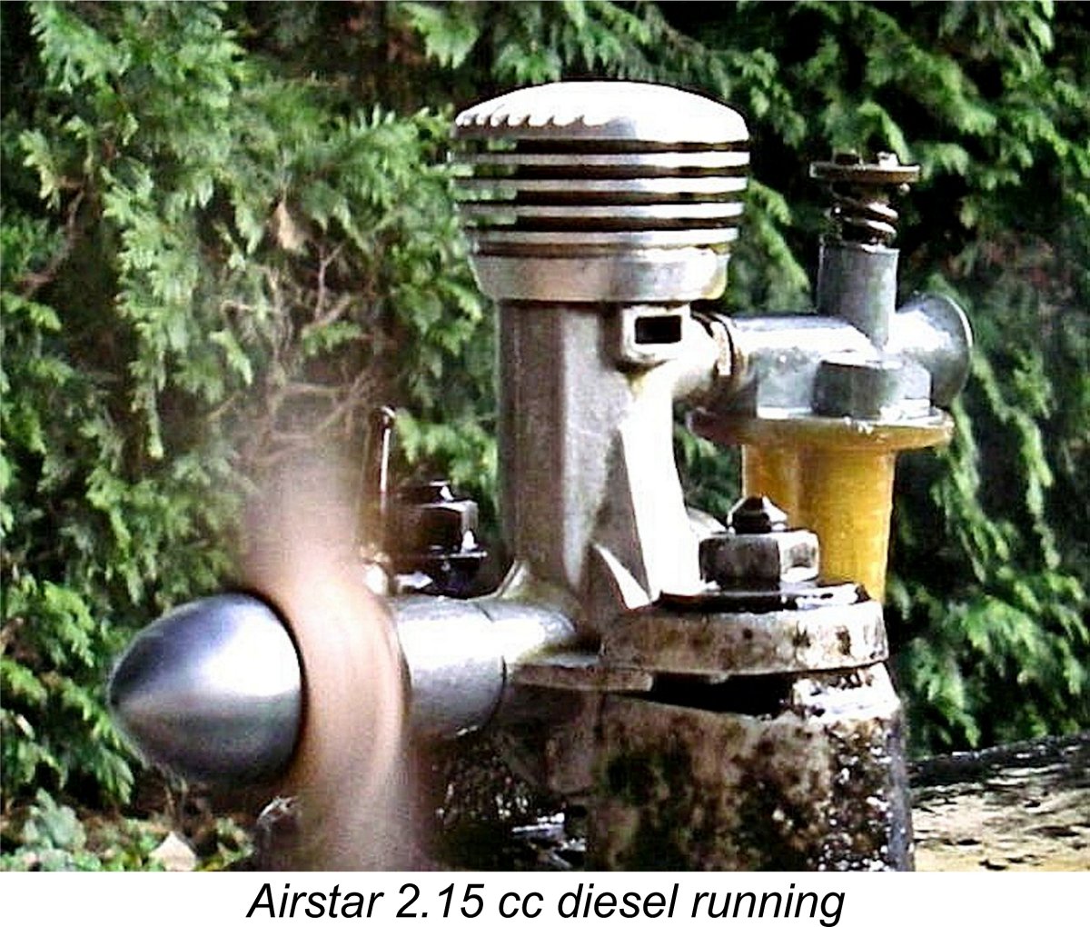
It's evident that the manufacturers appreciated this difficulty, since they were at great pains in their starting instructions to stipulate that ONE CHOKED FLICK only should be given as a preliminary to starting. Rather oddly, no mention was made of the potential use of an exhaust port prime. For me, the most effective approach turned out to be to fill the tank but not choke at all, relying on the engine's seemingly excellent suction to get the fuel flowing on a firng burst. All that was then required was a small prime to generate that initial firing burst. Using this approach, the engine proved to be a very prompt starter indeed, although even without choking it tended to start rich, picking up speed over the first few seconds following starting. Choking continued to have no effect other than to flood the crankcase. The compression control worked perfectly, providing excellent timing control while holding its settings securely during operation. The opposing friction and rod pressure rotating couples acting on the bushing (as discussed earlier) seemed to be in perfect balance. The fuel adjustment system worked fine as well, although I found that the settings were considerably less well defined than they would be with a conventional needle valve. It took quite a lot of movement of the "air throttle screw" to produce a noticeable difference in the running. Still, the optimal setting was quite easy to find, although it took the better part of a tankful of fuel to establish it the first time around. Thankfully, it turned out that the engine would start just fine on the running setting, so once established there was no need to change things for the same prop. Once set, the engine ran very smoothly, running the tank out cleanly to the last drop. The exhaust residues remained clear throughout, with no indication of accelerated wear or combustion issues. The only problem encoutered was that the tank tended to start to unscrew itself due to vibration, of which there was a noticeable amount. Still, this was a mild source of annoyance rather than a real problem - I just had to re-tighten the tank between runs. The vibration levels were certainly noticeable but were no worse than I would expect for an exaggeratedly long-stroke engine of this type. I found that my engine turned the relatively "slow" Top Flite Power Point wood prop at a steady 5,100 rpm - a bit slower than Brian Cox's example seen in his video. A considerably "faster" APC 10x6 allowed the engine to reach 5,700 rpm - a bit more like it! The 10x6 prop size actually seems quite appropriate for this unit. A full suite of props were then tried, with results as summarized below.
As can be seen, the engine displayed a very uniform rise towards a rather sharp peak, after which there was a dramaitic fall-off in power, as commonly seen with sideport diesels. The actual peak output achieved was a rather modest 0.089 BHP @ 6,800 rpm. This actually makes the Rev-Up 10x4 a vey suitable prop for bench running. There's clearly no point in pushing this engine past the 7,000 rpm mark. While this would have been a relatively competitive performance in late 1945 when the engine was designed by Roger Fargeas, the design had clearly been left far behind as of the latter half of 1948 when it first appeared in Britain. Model diesel engine design in that country had been progressing by leaps and bounds from 1946 onwards, and by August 1948 a number of commercial British diesels of generally similar size exceeded this level of performance, some of them by handsome margins.
In my opinion, these results go far towards explaining the Airstar's very brief market tenure. Why would anyone buy an Airstar with these alternatives to choose from, among others? Basically, the Airstar was a late 1945 design, the release of which was delayed by circumstances until the latter half of 1948, by which time other designs had left it in their wake in performance terms. It was a very well-made and competitively-priced engine which handled and ran more than acceptably. However, these attributes were clearly not enough to secure its place in the marketplace. All of this having been said, I thoroughly enjoyed conducting this test of a very rare engine. It came through the test with flying colours, clearly ready to run as long as required. No mechanical problems were encountered at any time - the impression was that this is a very sturdy and well-constructed unit which would have given long and faithful service to any owner. It's too bad that the 2 year delay in its release denied it the opportunity to demonstrate its true worth more widely. Conclusion
However, I have to say that this is one engine which I sincerely wish was far more common than it is! It wouldn’t be so rare and hence desirable in collecting terms, but far more people would then have a chance to experience it at first hand. The Airstar is such a refreshingly "different" and altogether satisfying engine to handle that I genuinely regret the fact that relatively few collectors will ever have the opportunity to do so. For my part, I thoroughly enjoyed both examining and running this engine, which has qualities which richly merit far wider appreciation than the surviving numbers allow. The best that I can do is share my experiences to the extent possible. I hope that through this article I’ve succeeded in doing so, at least to some degree. Good examples of the Airstar are very seldom encountered today. If you ever get the chance, don’t hesitate - anyone who likes classic model diesels can’t fail to really appreciate this one! Hats off to Roger Fargeas and the Steward company! ___________________________ Article © Adrian C. Duncan, Coquitlam, British Columbia, Canada First published April 2021 |
||
 In this article, I’ll present a review and test of a rare and somewhat enigmatic engine dating from the late 1940's. My subject will be the Airstar 2.15 cc diesel, ostensibly from Luton in Bedfordshire, England.
 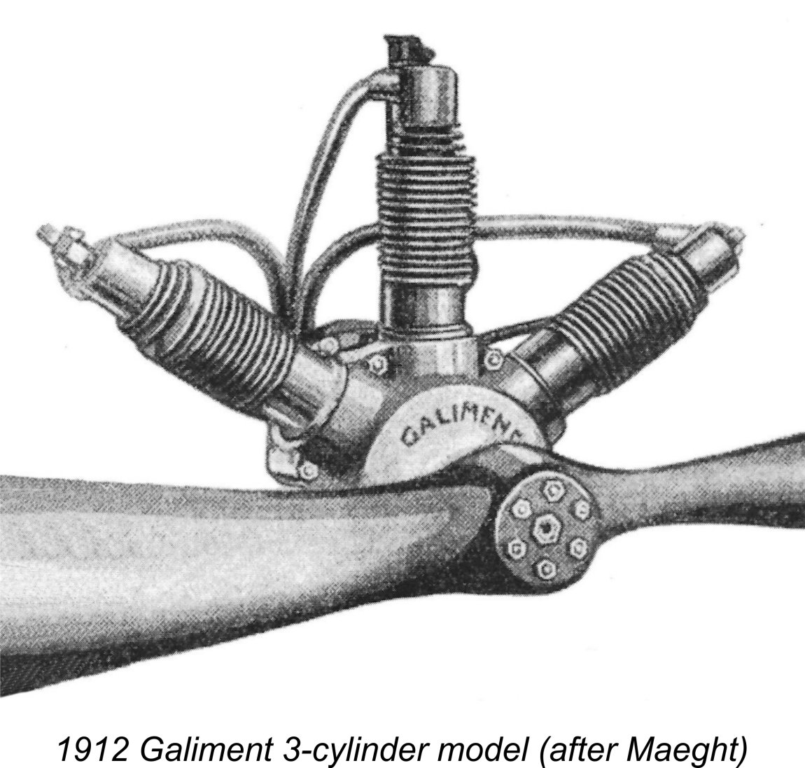 A number of the illustrations near the beginning of this section of the article are drawn from Adrien Maeght's very informative book ”
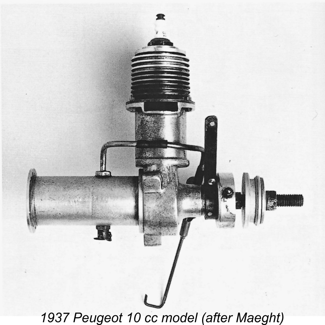 It was not until 1930 that commercial manufacture of model aero engines resumed in France, with both Rebous and Fameaux commencing the commercial manufacture of model aero engines on a relatively small scale. The French power aeromodelling movement began to make a slow recovery from that point onwards.
 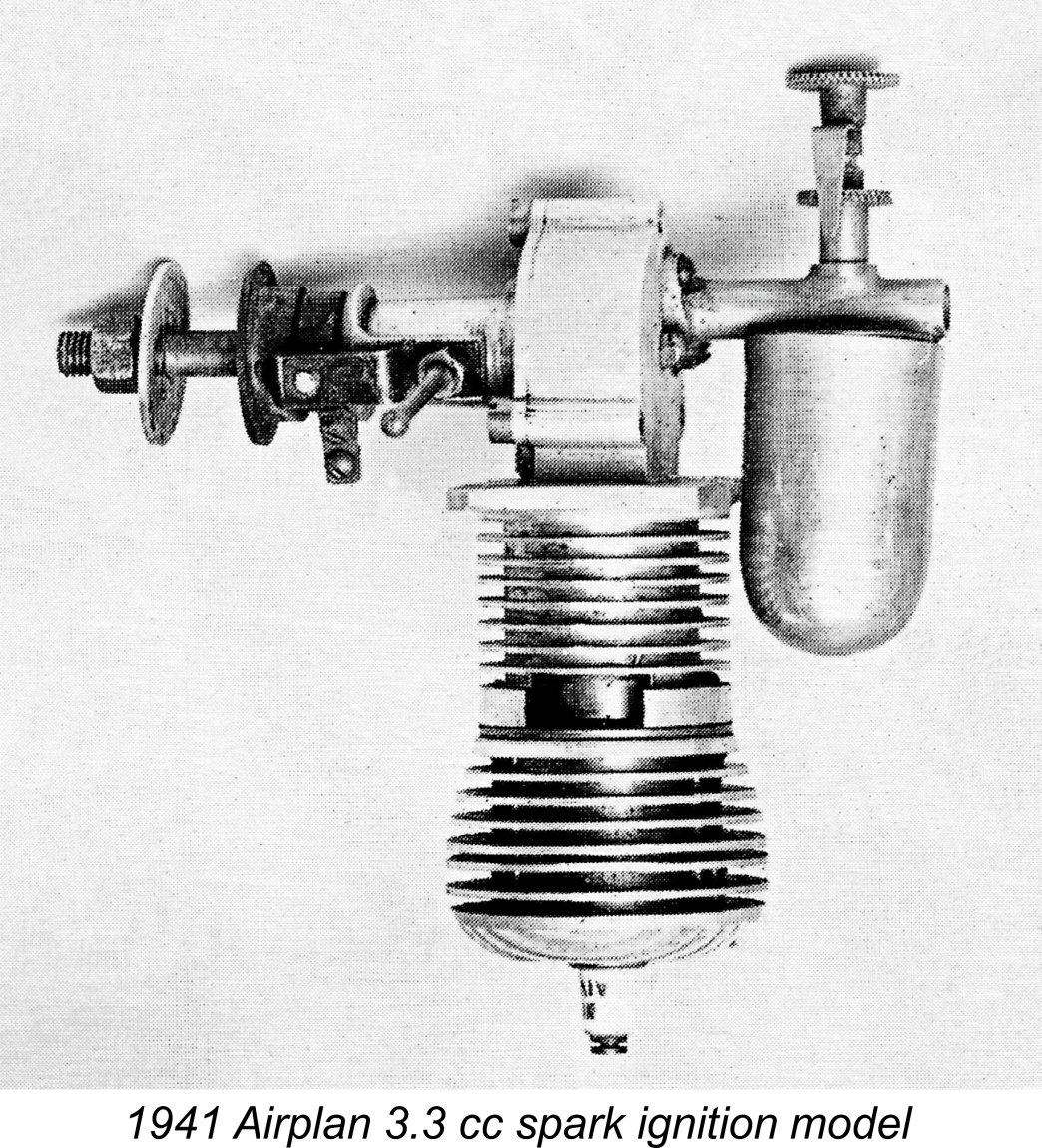 It’s difficult at this distance in time to comment on the implications of this situation. It would appear that, unlike their attitude in other occupied countries, the Germans either permitted the operation of powered models or at the very least turned an official blind eye to it as a matter of policy. It seems inconceivable that so many model engine manufacturers could have openly engaged in the business without official German endorsement or at least toleration. It may be that the occupying power saw the encouragement of hobby activities as a means of defusing resentment of the occupation among ordinary French citizens.
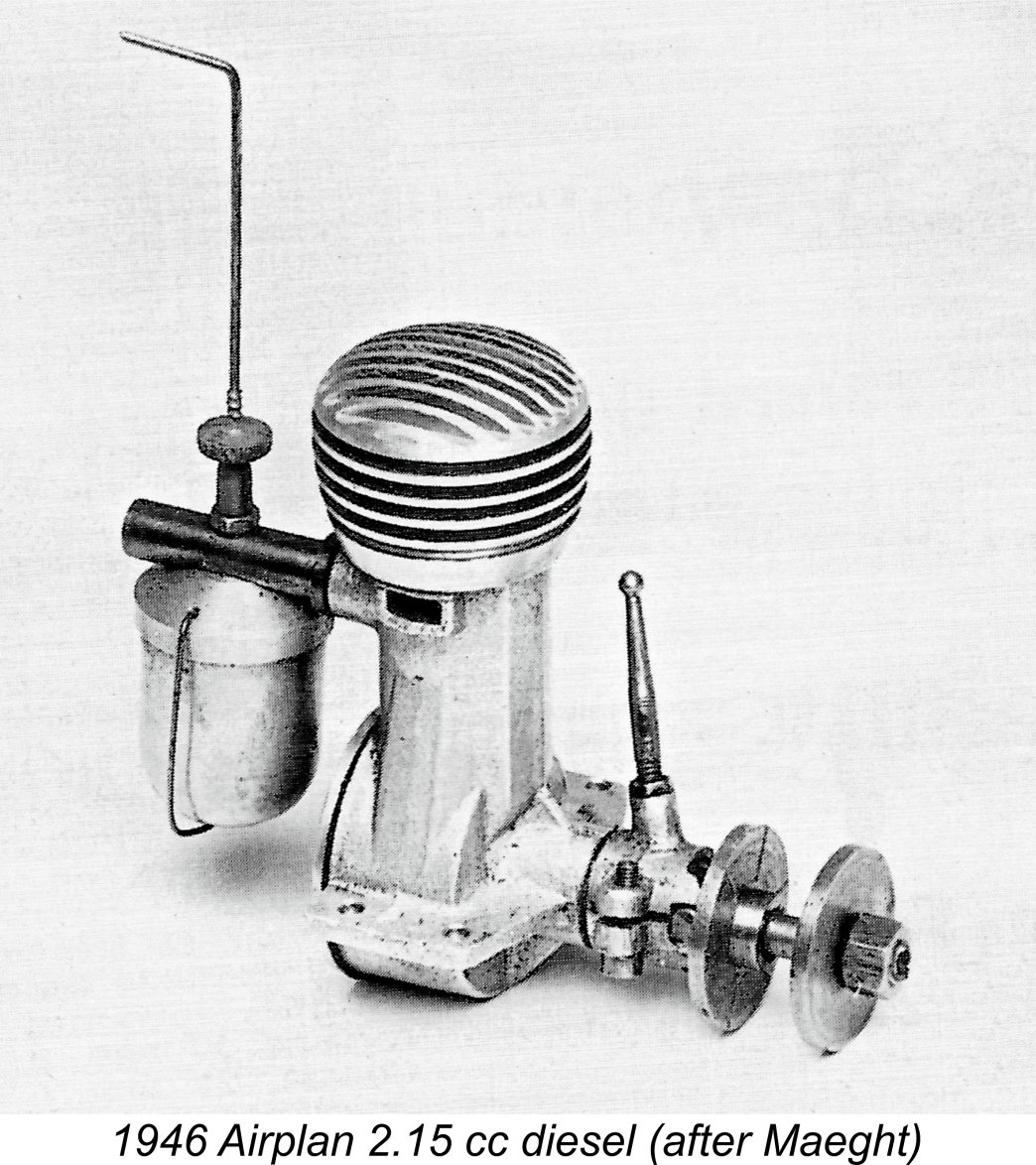 Later in 1945, recognizing the operational limitations of fixed compression, Fargeas designed a 2.15 cc Airplan diesel having variable compression using the eccentric main bearing system, of which much more below in its place. However, just as production of this model was getting started, Fargeas left Airplan to rejoin his brother Georges in establishing the Ouragan (Hurricane) operation to make engines on his own account. Fargeas’s departure seems to have put an end to the Airplan model engine marketing venture - production evidently ceased and no further designs were to appear under the Airplan name.
 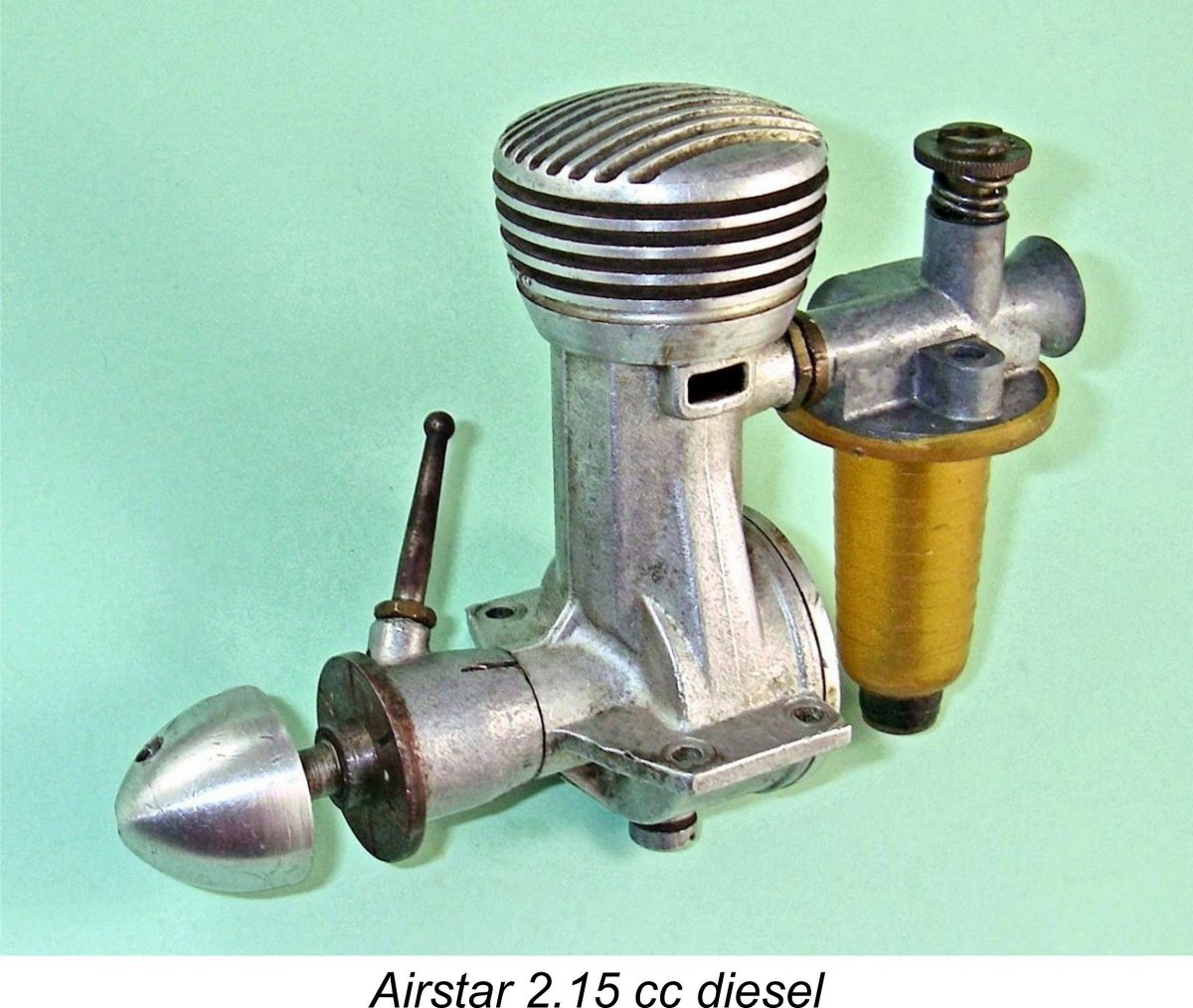 Following the sale, these assets were transferred to Steward’s Luton plant, where they were eventually built up into complete engines. The name of the engine was Anglicized into Airstar, allowing the engines to be marketed as “British” products. However, a dead giveaway was the fact that these “British” engines used metric threads and major dimensions - most improbable features of an all-British product of the late 1940’s!
 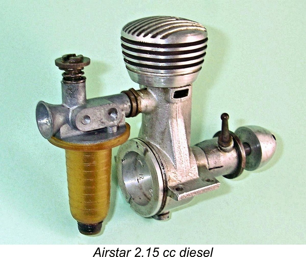 Despite the favourable selling price, relatively few examples appear to have been produced and sold. This may suggest that the Steward company focused its efforts upon the construction of engines from the components obtained from Airplan - they do not appear to have produced complete engines themselves from scratch, although they evidently did make a few replacement components to reflect their own design thinking. They may also have produced some duplicate components to make up for shortfalls in stocks of the French-made items. They seem to have produced their own fuel supply assemblies, compression adjustment collars and alloy spinner nuts, since these differ considerably from the components used in the original Airplan models (see below). In all probability they allowed their production volume to be dictated by the number of available Airplan crankcases.
 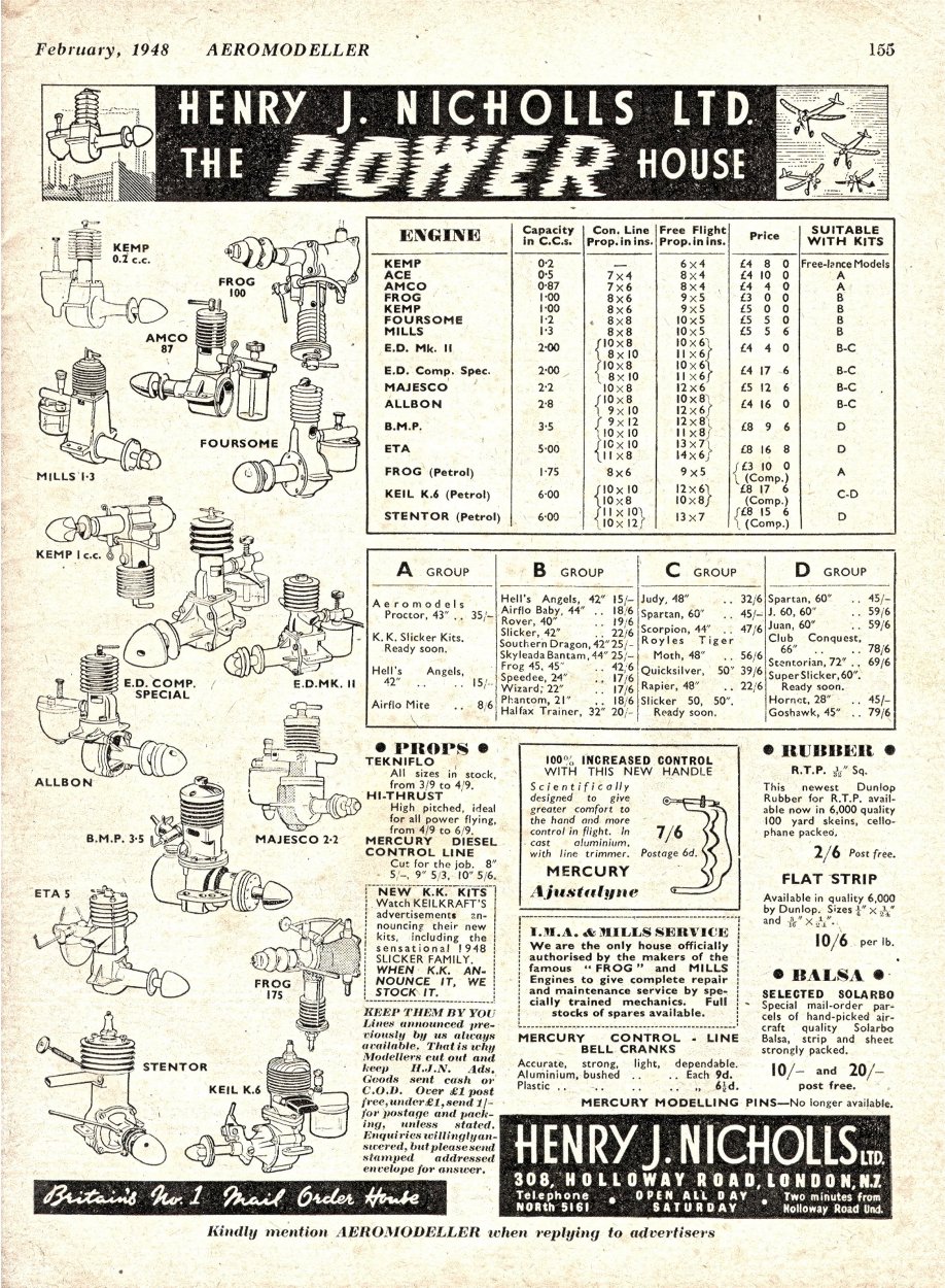 However, my own extensive research has turned up absolutely no evidence to support this date. On the contrary, I’ve assembled a very substantial body of evidence to suggest that the engine’s true introductory date was mid to late 1948. Let’s see if I can convince you …………
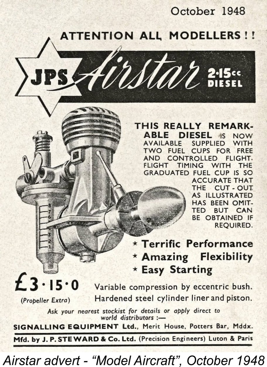
 The eccentric bearing compression adjustment system is a classic expression of the old saying that there’s more than one way to skin a 'gator! Varying the compression ratio of a model diesel is achieved by varying the volume of the combustion chamber at top dead centre. Most conventional designs accomplish this through the use of a moveable contra piston which seals the bore at the top and serves as the working cylinder head. Changing the elevation of this component changes the distance between it and the piston crown at top dead centre, thus changing the combustion chamber volume and hence the working compression ratio.
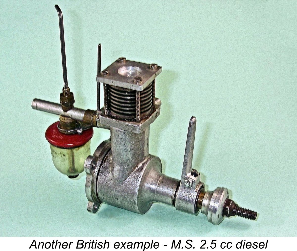 Conventional bushings of this type are usually a very tight press or shrink fit in the surrounding casting material to prevent rotation during operation. However, in the case of an engine such as this one the bushing is a smooth push fit in the centrally-bored main bearing casting, leaving it well supported but free to rotate within the casting. Since I was unable to dismantle my Airstar sufficiently for internal photographic purposes (see below), the attached images of the similarly-designed
 For all of these reasons, the arrangement is widely employed today in full-sized engine practise - the gas engine in the ground-breaking Toyota Prius hybrid is a notable example. In addition, the Desaxe principle has been quite commonly used in certain model engine ranges, the Fox marque being perhaps the best-known example.
 The final potential problem was pointed out by D. J. Laidlaw-Dickson in his previously-cited Spring 1948 article in "Model Mechanic" magazine. While discussing the similarly-controlled
 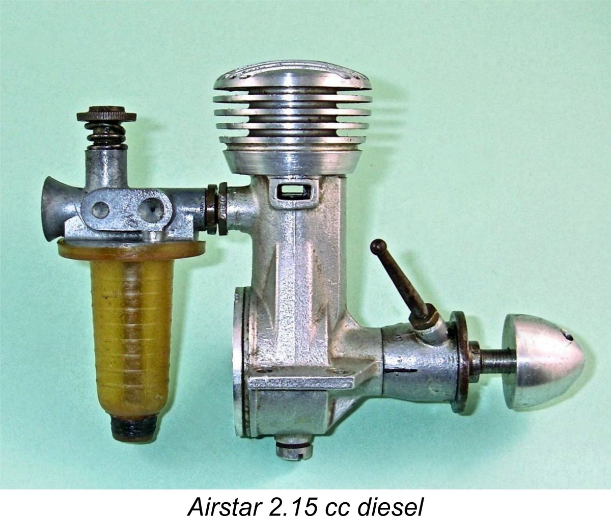 A good deal of useful descriptive information may be derived from the engine’s previously-cited inclusion in Appendix II of Ron Warring’s invaluable reference book “
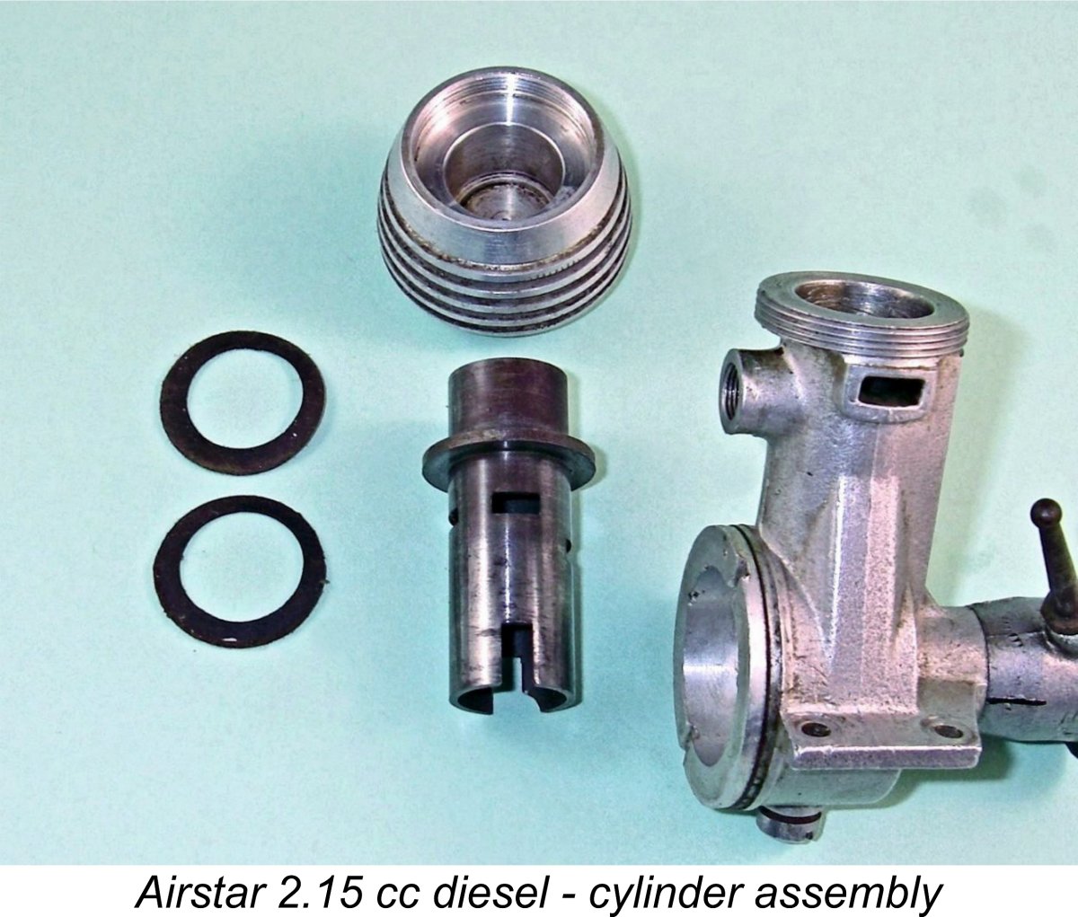 Instead, the designer has utilized a closely-fitting blind-bored cooling jacket which engages with an external thread machined onto the top of the upper crankcase casting immediately above the exhaust ducts. This jacket actually seals at its base against a wide flange located part-way down the cylinder liner above the exhaust ports. This flange bears against the top of the crankcase casting and is held down by the screw-on cooling jacket. A set of fibre gaskets maintains a gas-tight seal between the cooling jacket and the cylinder flange. Hopefully the attached component view will help to clarify this description.
 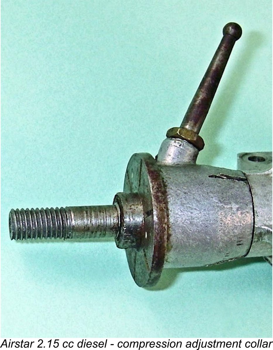 Like the cylinder liner, the piston is also made of hardened 3% nickel steel. As I've previously stated in connection with other engines having a similar steel-on-steel piston/cylinder combination, this can be a highly problematic combination. The initial fit has to be absolutely perfect, since both components being hardened means that running-in wear will be negligible. In particular, if the piston is the slightest bit too tightly fitted, the engine will tend to nip up and sag or even stop when warmed up. Thankfully, the manufacturers of the Airstar appear to have done a first-class job - the fit seems just about perfect by feel.
 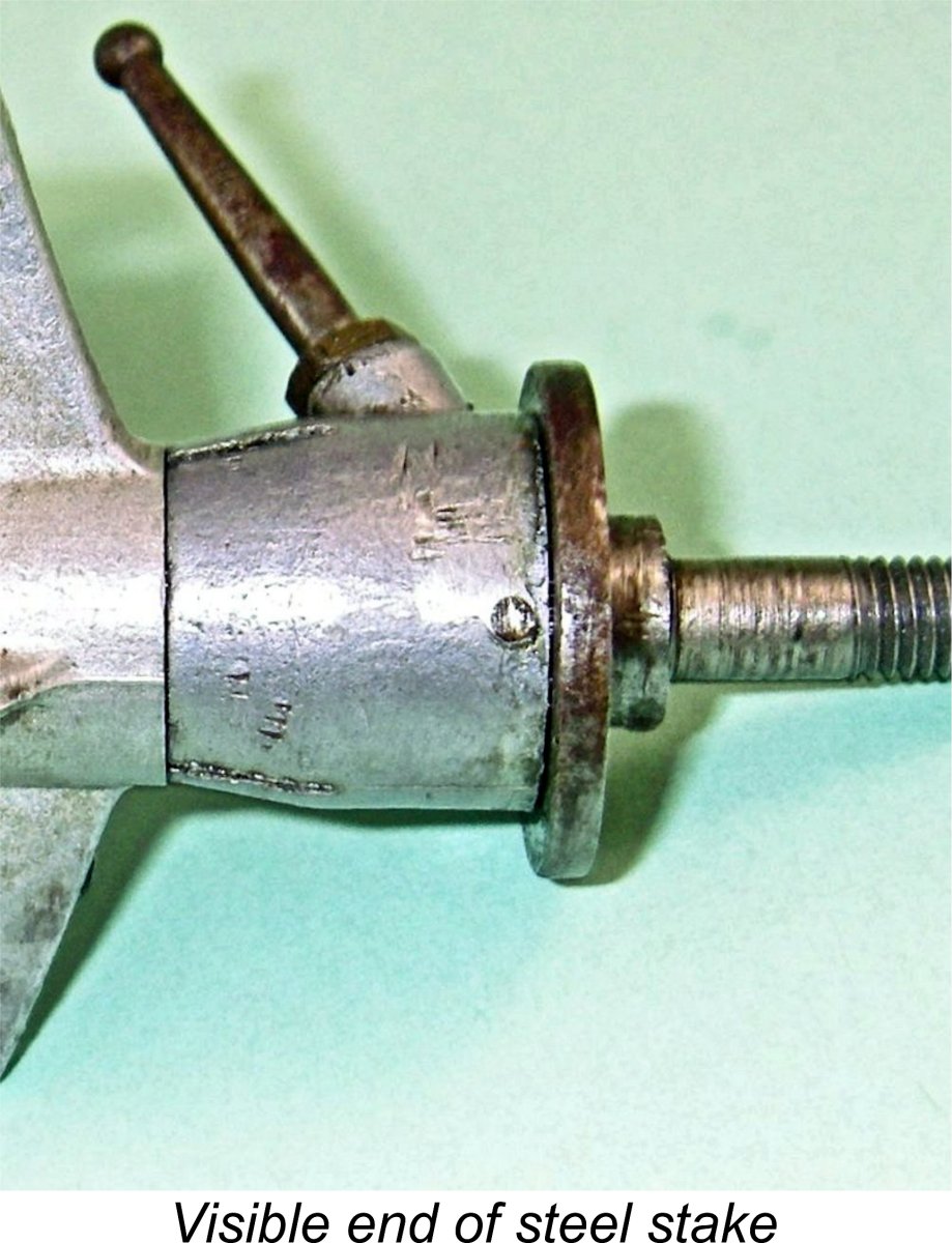 The Airstar departed from this arrangement, using a different collar which lacked a clamp bolt, instead being provided with a three-segment split at the rear. This section was in effect a split thimble which could be squeezed to create a smooth but firm fit between the rear end of the collar and the external bearing on which it was mounted. Apart from its different design, the fact that this component was almost certainly one of those produced by Steward is reflected in the readily-apparent use of a different casting alloy.
 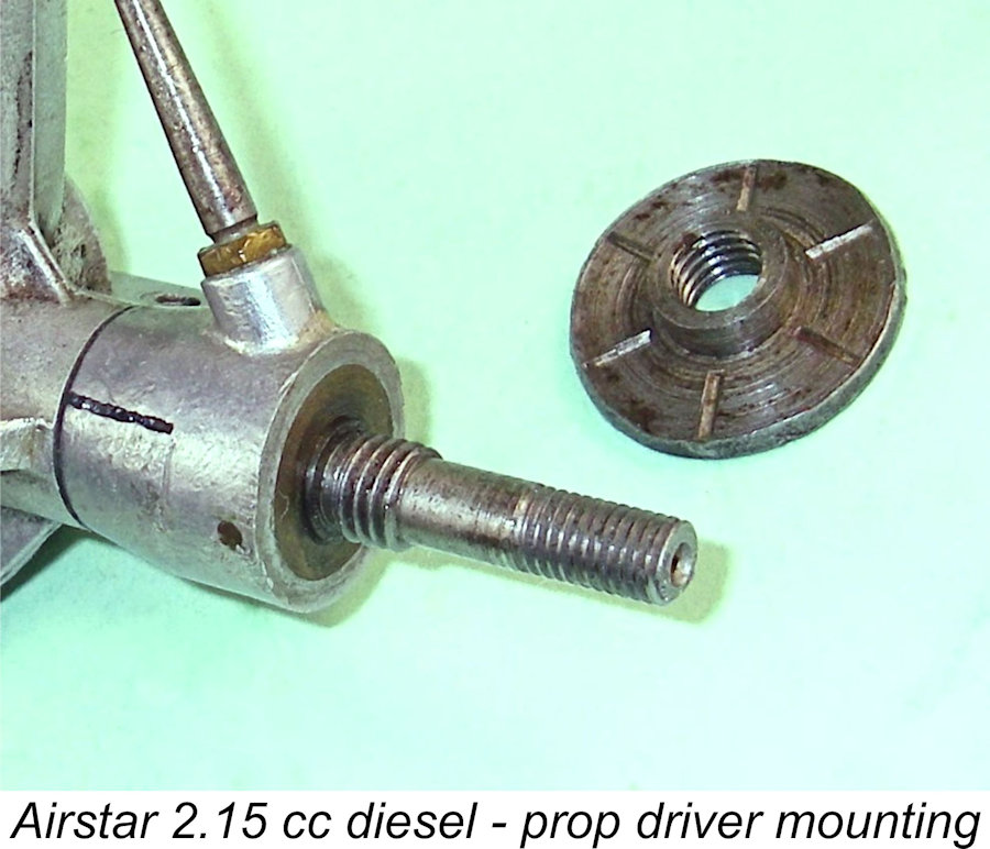 The rotation of the collar is not constrained in any way, leaving it free to rotate through a full 360 degrees. This allows it to be rotated in either direction to any desired degree. The attached images of my example show the timer arm in its minimum compression location. Any rotation either way from this position will increase compression by raising the shaft. Ideally, the arm should be rotated in the operating direction to increase compression. The basis for this recommendation was fully discussed in the previous section of this article.
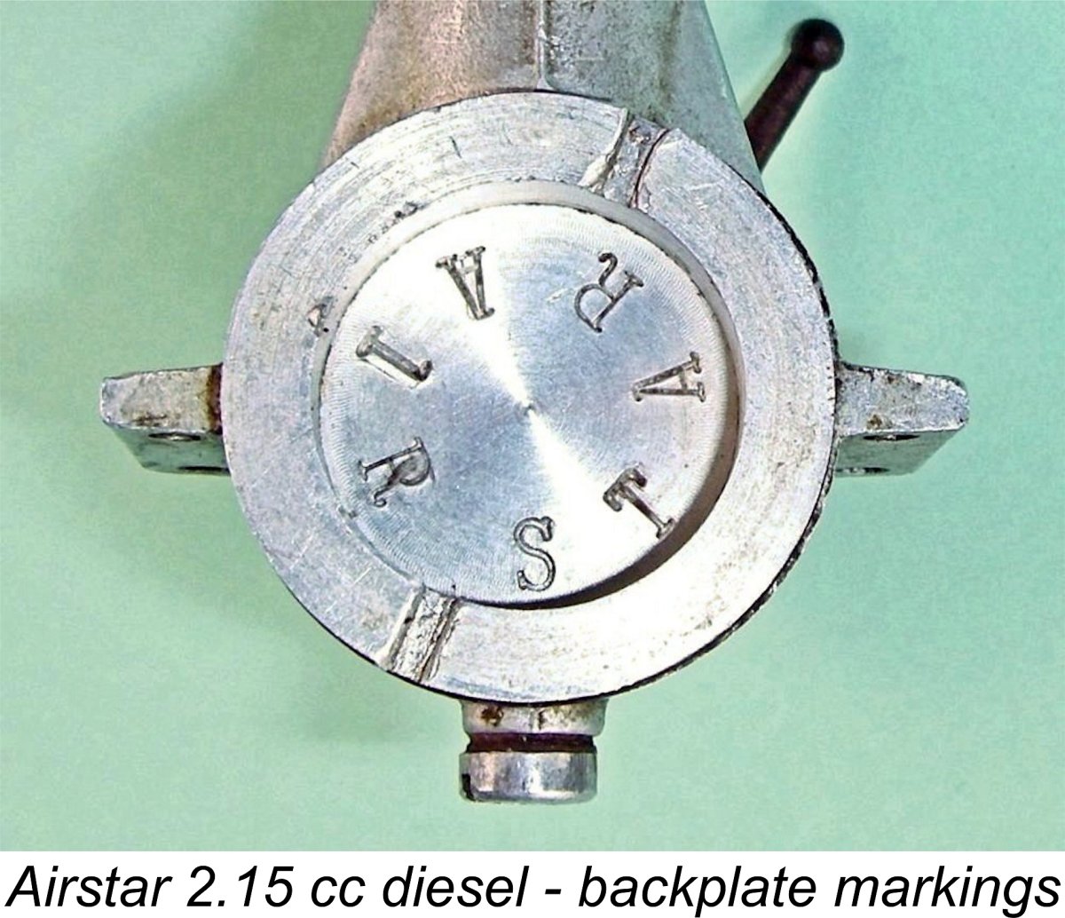
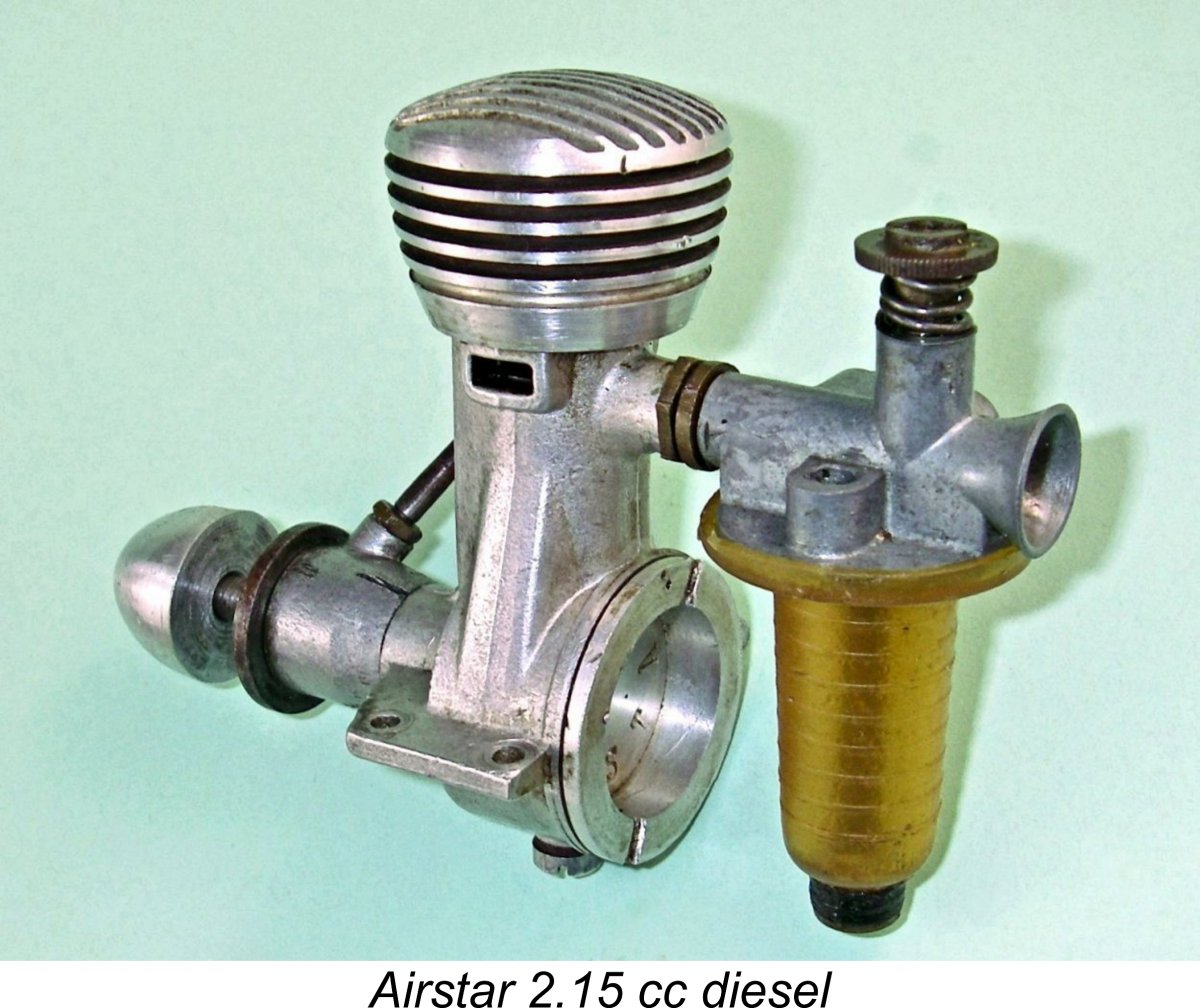
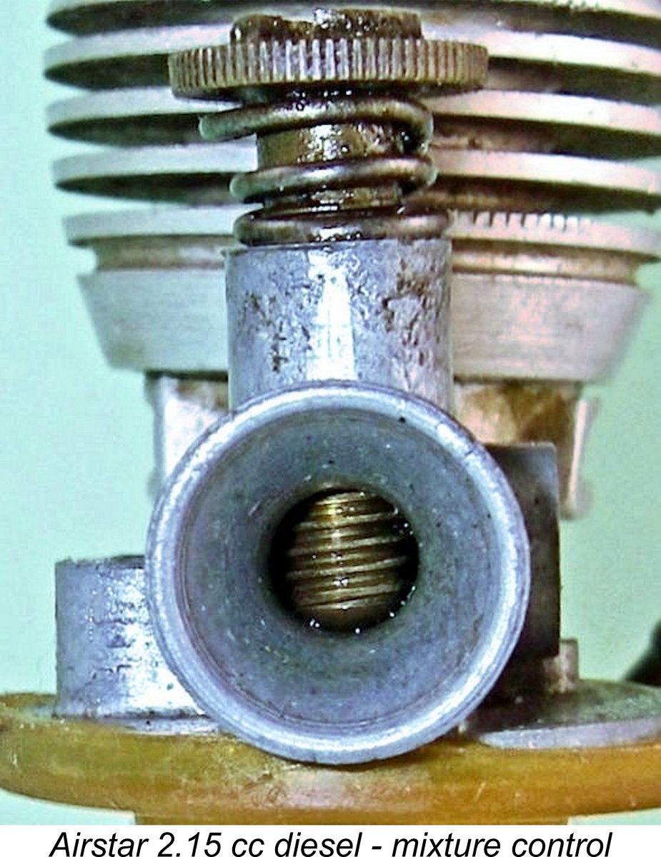 The observant reader will have noticed that what appears to be the needle valve on the Airstar is not aligned with the fuel pickup tube in the usual way. This is because the Airstar embodies the very unusual feature of having no fuel needle - yet another of its highly individualistic attributes! The fuel is supplied to the intake through a small fixed jet at the upper end of the screw-in brass fuel pickup tube. This jet protrudes into the centre of the venturi throat when the pickup tube is screwed home.
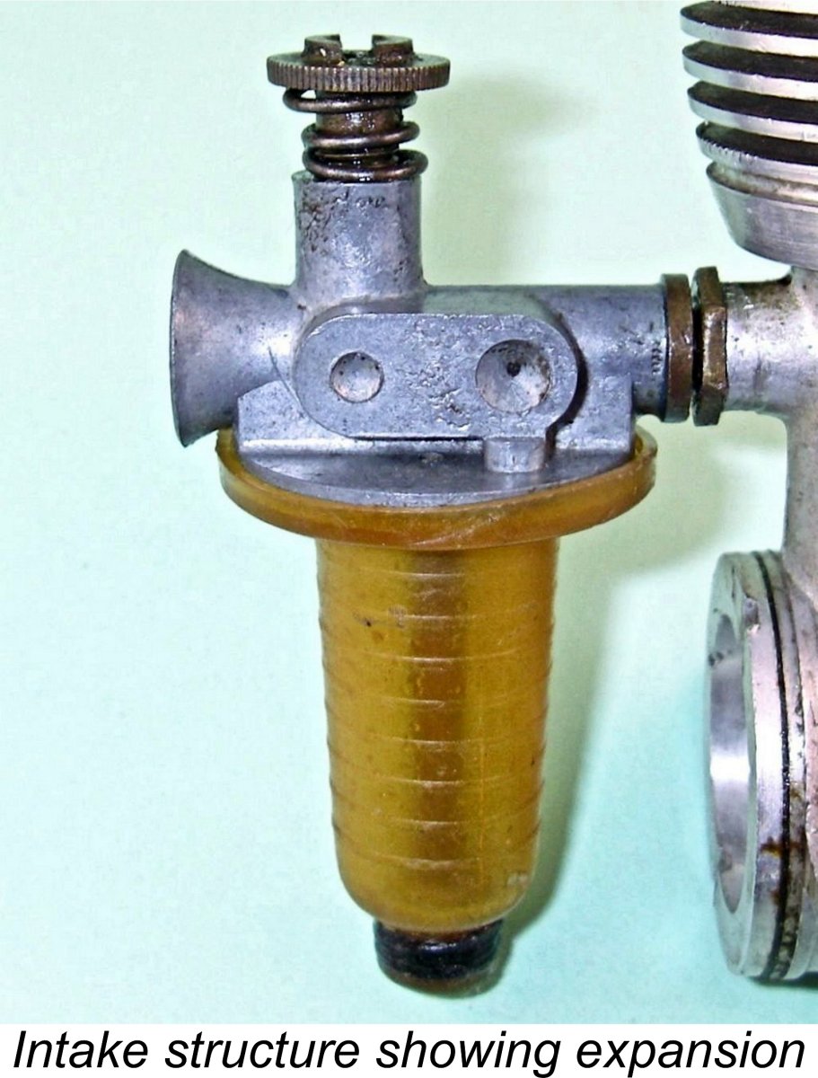
 comment that has been made regarding this feature since Warring mentioned it in the caption to the image in his book. It's a salutary reminder to me that all sources of information have to be identified and carefully checked if one is to claim any credibility for one's research.......... big thanks to Maris for helping me to do so in the present case.
 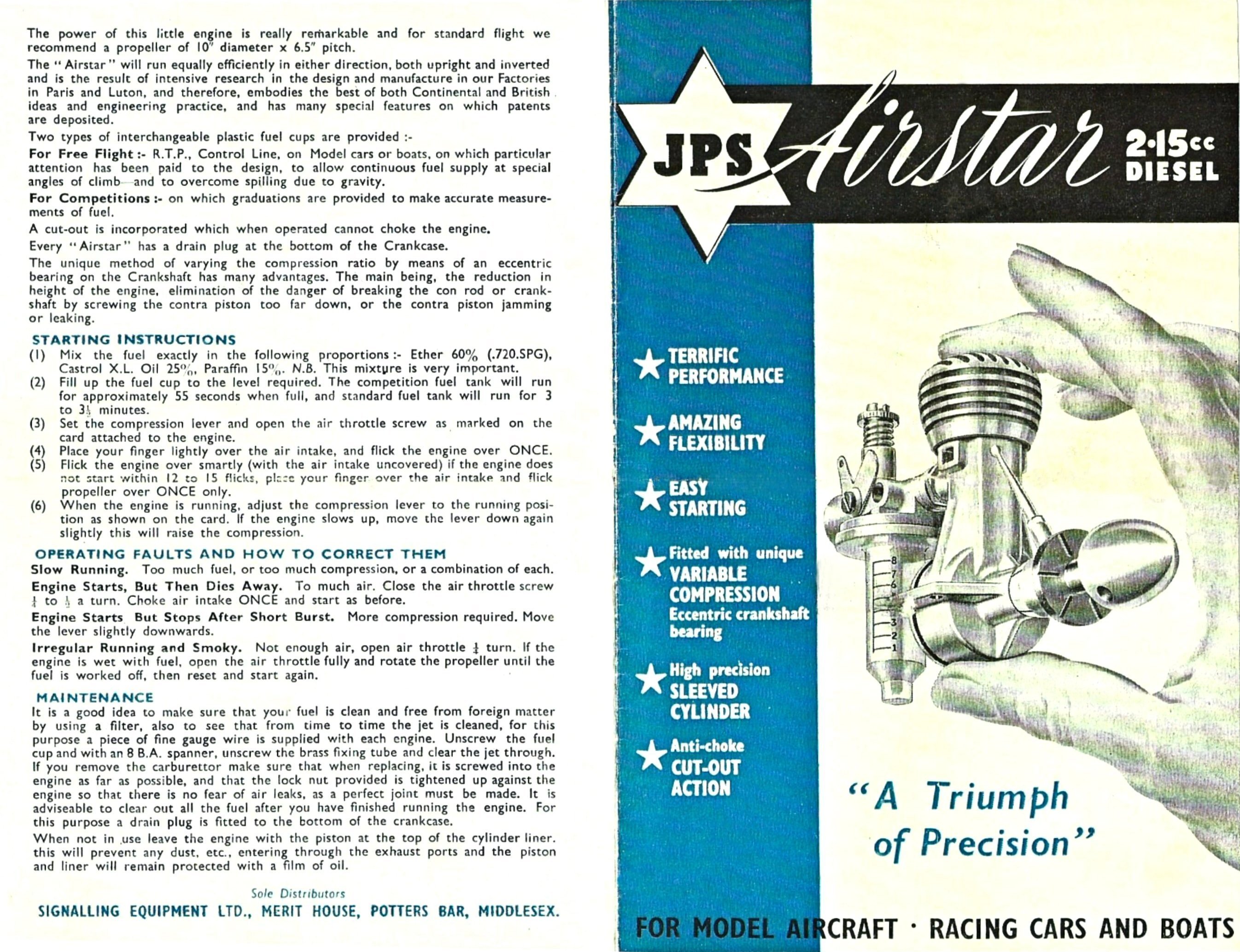 I'm always immensely grateful for any assistance with these articles that I receive from my valued readers. In the present instance I have to express my deepest appreciation for the help offered by reader Stewart McLaren, owner of the previously-mentioned example of the Airstar numbered II 8 639. Stewart tells me that when he started collecting model aero engines over forty years ago, that Airstar was among his first acquisitions!
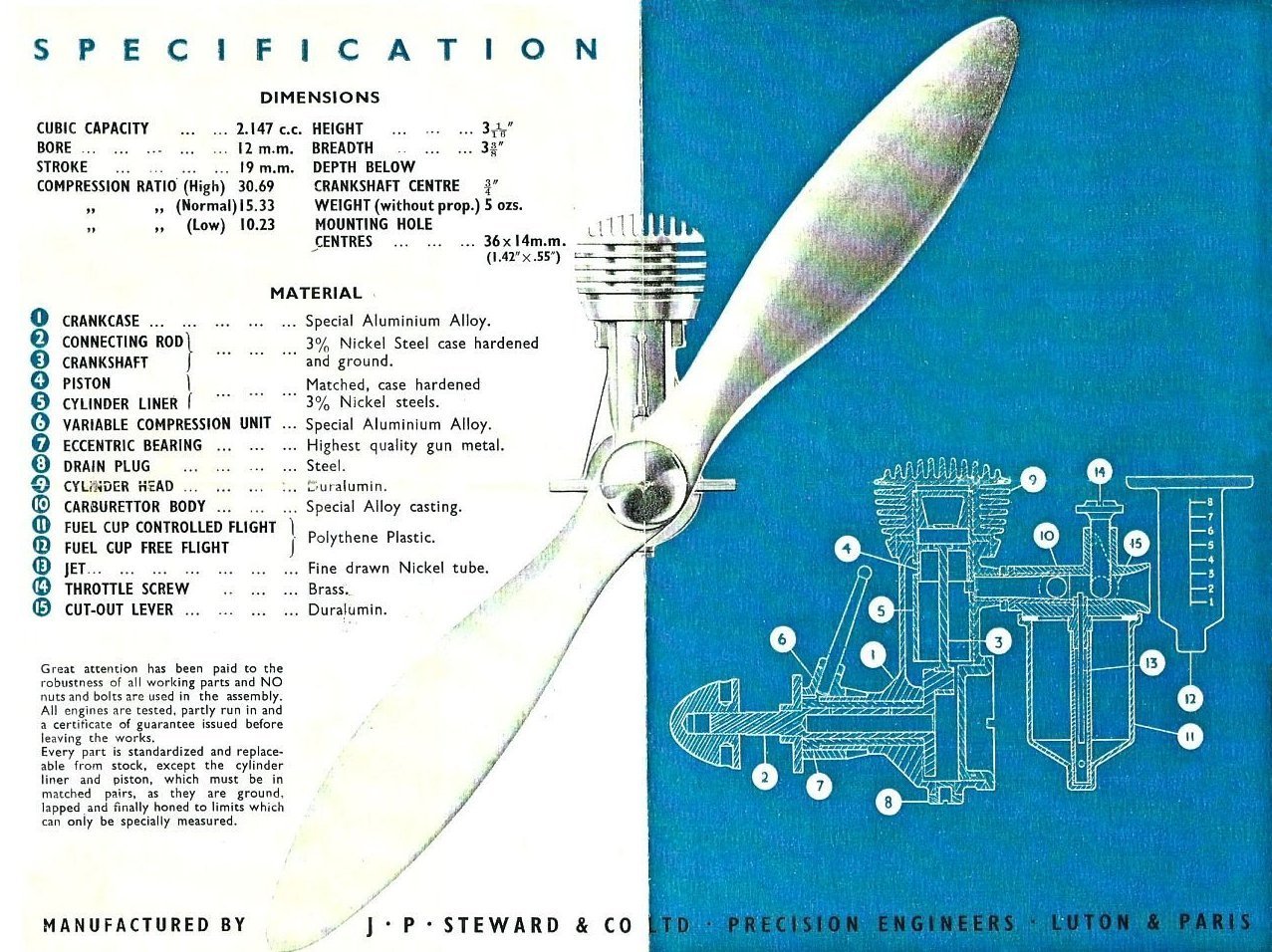
 I quickly figured out what was happening. Since the fuel jet is fixed, it's always "wide open" to the venturi throat. So choking the engine is like choking a conventional unit with the needle valve set on maximum rich! This is bound to draw in a serious slug of fuel on each choked flick. This is why the case became flooded with my two choked flicks.
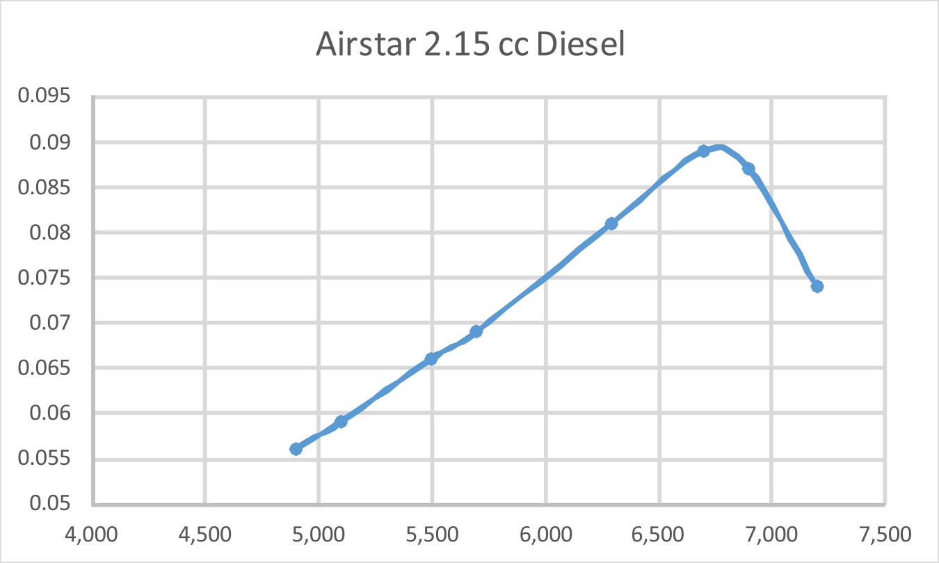
 To take perhaps the most prominent example, the far lighter, less complex and more powerful
 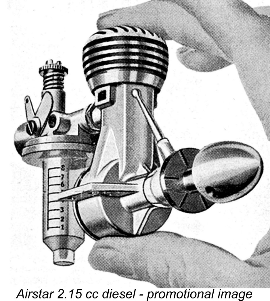 Owning and operating an engine of this rarity is undoubtedly a very special experience - one which relatively few collectors will ever actually share. There's an immense amount of satisfaction in acquiring and then actually operating such an engine.
 | |