
|
|
Warwickshire Rarities - the Rawlings Diesels
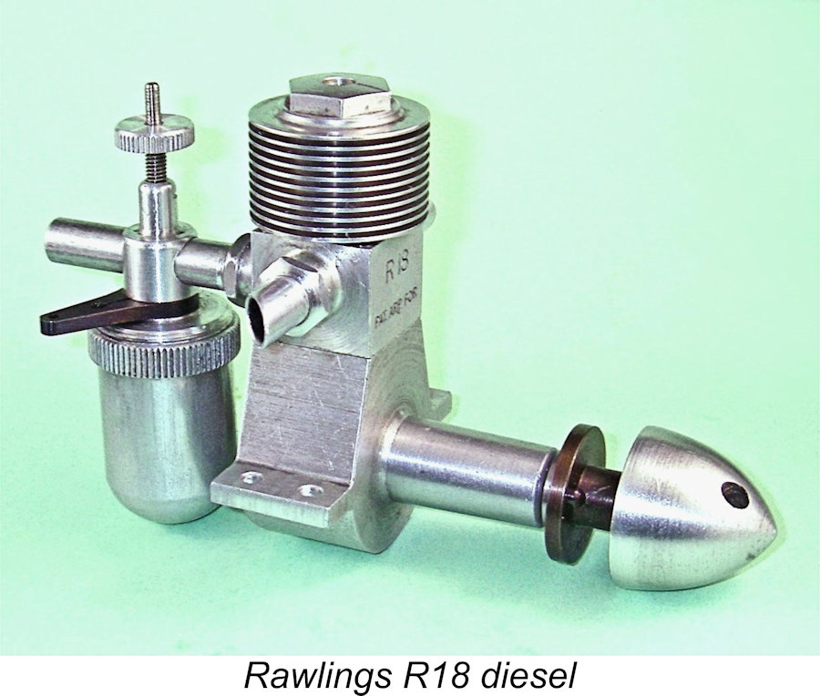
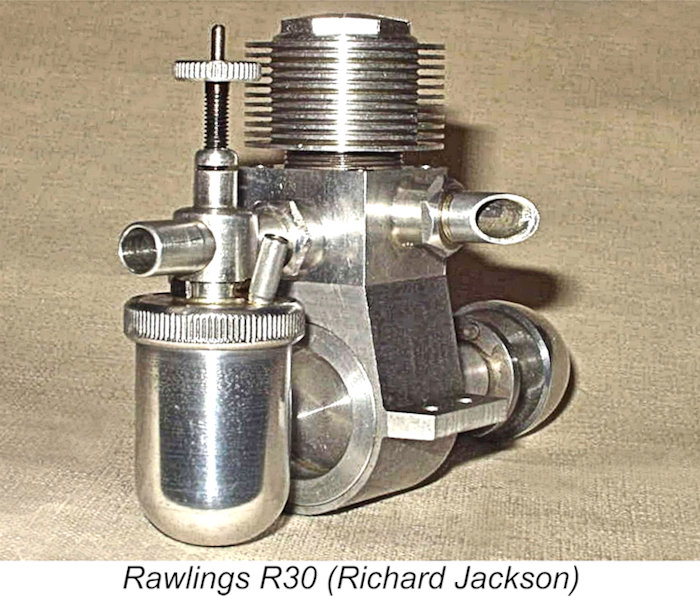
The Rawlings range consisted of two identically-designed sideport diesels – the R18 of 1.81 cc displacement and the 3.14 cc R30 model. Both units were produced during the period mid-1948 to mid-1949, with a reproduction series using mainly original components appearing much later, of which more below in its place. They were relatively complex designs which were built to very high standards in extremely small numbers, making them very rare and much-sought after units today. For such seldom-encountered engines, the technical characteristics of the Rawlings diesels are unusually well documented. This is largely because both models were the subject of descriptive articles written some years ago by Richard Jackson of Dorset, England and published on the late Ron Chernich’s sadly now-frozen “Model Engine News” (MEN) website. At his time of writing, Richard was fortunate enough to own fine reproduction examples of both models, hence being able to describe them in considerable detail at first hand, complete with photographs. His illustrated descriptions of the Rawlings R18 and Rawlings R30 offerings may still be found on MEN.
I’m able to supplement Richard’s work to some extent due to the fortunate circumstance that I’m lucky enough to own a fine LNIB example of the R18 model, albeit one which was assembled much later using mainly original components. More of that matter below in its place. Richard didn’t test this model, an omission which I was in a position to rectify. In addition, thanks to the help provided by my good mate Gordon Beeby of Australia, I’ve also unearthed a good deal of information relating to the engines’ production history. Another valuable source of information is to be found in the pages of the late O. F. W. Fisher’s occasionally misleading but nonetheless very useful little book entitled “Collector’s Guide to Model Aero Engines”. Fisher seems to have established a close relationship with George Rawlings, owner of the company which made the engines. He was able to obtain some very useful first-hand information about the Rawlings company in general, recording his findings in his 1977 book. Fisher actually claimed to be the owner of the last example of each engine to leave the factory. The existence of the Rawlings engines was acknowledged in Ron Warring’s early 1949 book entitled “Miniature Aero Motors”. However, Warring provided absolutely no data on them. It appears that Warring never had a chance to examine either model in person – all that he knew about them was their names! I think that we can do better…………. Armed with the information to be gleaned from the above sources, let’s see what can be done to present a summary of this very exclusive model engine range. The Rawlings Range – General Observations As I’ve pointed out in several earlier articles, Britain was actually a late-comer in the field of model diesel engine design and production. By the time that the first British production diesels began to appear in mid-1946, such engines had been in varying scales of production in a number of Continental countries for as much as five years! This situation was largely a result of the fact that as one of the main combatant nations, and one which was under constant direct assault, Britain had diverted the vast majority of its precision engineering resources into war-related production, leaving neither time nor opportunity for such “trivial” matters as model engine production. Even if this had not been the case, the wartime ban on the flying of I/C powered model aircraft would have completely dried up the market. The consequence was that during the war there were many relatively small precision engineering firms throughout the country engaged in war production activities. However, all wars come to an end, and when WW2 finally ground to a halt many of these firms were left looking for alternative ways of utilizing the capabilities that they had developed during the war years. Naturally enough, a number of them looked at model engine manufacture as a possible solution to their problems.
During WW2, the company had produced precision gauges, a product line calling for an exceptionally high level of manufacturing precision and consistency. The production of model diesel engines, an activity calling for a similar level of precision, must have presented itself as a logical manufacturing avenue for the company to pursue as a peacetime business line.
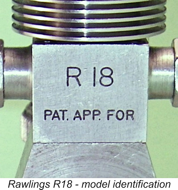
The front faces of the aluminium alloy "port blocks" on top of the crankcases were neatly stamped with the engine’s model designation plus the notification “PAT. APP. FOR”. The records show that George William Rawlings took out two Patents relating to model diesel engines. An examination of the claims embodied in the Rawlings model engine Patents is quite informative.
The key points to note here are firstly that between them, these Patents covered the two central design concepts around which the engines were constructed and which set them apart from the others. The second point is the fact that both of these Patents were applied for on August 28th, 1947, almost a full year prior to the mid-1948 appearance of the Rawlings engines. It follows quite logically that the design of the Rawlings diesels must have been essentially complete by mid-1947. So why didn’t Rawlings release the engines then? The only answers to this question that I can come up with are either that pressure of other work precluded an earlier release, or that George Rawlings may have been waiting for the Patents to be approved before releasing the engines to the market. If the latter, this was a serious miscalculation given the rate at which model engine design was evolving at the time as well as the glacial pace of Patent application approvals. Such a delay merely had the effect of making the engines a year or more out of date by the time of their eventual release. Moreover, the delay did not achieve its objective – the engines were finally released with the Patents still pending. Their subsequent approvals actually post-dated the cessation of production! Having examined the circumstances surrounding the release of the Rawlings diesels, let’s now have a look at their subsequent marketing history. In the almost complete absence of any contemporary media commentary, we’ll have to rely on the advertising record for the most part. Marketing History
The October 1948 issue of “Aeromodeller” included a full report by Ted Buxton on the 3rd annual All-Herts Model Aircraft Rally held at the Handley-Page Airfield at Radlett, Hertfordshire on August 22nd, 1948. This was a major competition, attracting no fewer than 348 entries covering 8 categories, including such luminaries as Dennis Allen and Norman Marcus. Entrants came from as far afield as East London, Croydon, Southampton, Worcester and Warwick. Ted Buxton’s report included the statement that one W. G. Johnson “from way up in Warwickshire” finished in second place in the Free Flight Power category “using one of the hot new Rawlings diesels for power”. Whether this was an R18 or an R30 was not made clear. Regardless, this statement confirms that examples of the “new” Rawlings engines had begun to appear on British flying fields by August 1948, almost certainly confirming that the engines must have been introduced in June or July of 1948.
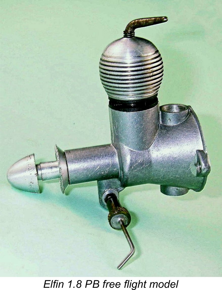
However, it must be recalled that the release of the R18 more or less coincided with the appearance of the Elfin 1.8 diesel from Liverpool, which was first advertised by Henry J. Nicolls in July 1948. The Elfin posed a very direct performance-based challenge to the cited “hot” status of the Rawlings! It must have had a considerable negative effect upon the R18’s market prospects, especially given the fact that the far simpler construction of the high-revving and ultra-lightweight Elfin allowed it to be retailed at £4 0s 0d, thus undercutting the initial asking price of the R18 by 17 shillings and sixpence (£0.87).
That having been said, Gordon’s findings make it clear that the eventual failure of the Rawlings marque to make much of a splash in the British marketplace was definitely not for want of trying! Although Rawlings & Partners never placed advertisements in their own name, the company was successful in arranging for a number of nationally-advertising retailers to list their products. During the period October 1948 – January 1950 Gordon found no fewer than 20 listings of the Rawlings engines in national advertisements placed by a number of prominent dealerships in various locations.
The Rawlings diesels also appeared in advertisements place by Watkins and Arthur Mullett of Brighton, Sussex in the 1949 Ian Allan Model Aviation series. Oddly enough, Mullett never included the Rawlings diesels in any of his regular monthly advertising placements in “Aeromodeller” magazine. The impression is that he viewed the engines as insufficiently strong sellers to justify their inclusion in an ongoing national advertising campaign. This may have been true for other retailers as well – the engines may have been more widely distributed than the advertising record suggests. By far the most persistent retailer of the Rawlings diesels was Paramount Model Aviation of Westcliff-on-Sea in Essex – a long way from Warwickshire! Paramount advertised the Rawlings engines no fewer than eight times during the period from December 1948 to July Paramount never advertised the R30 at any time, focusing on the 1.8 cc R18 model throughout. Most intriguingly, Paramount never referred to the R18 by that name, instead citing it as the “Bert Rawlings 1.8 cc diesel”, or occasionally as the “Berks-Rawlings 1.8 cc” model, the latter possibly being a typo. No other advertisers referred to the engines in this way. Could the Rawlings engines have been designed by a relative of George Rawlings named Albert?!? There’s a story there, but we’ll probably never know ………. Somewhat surprisingly, the price of the R18 in the final advertisement of January 1950 remained unchanged at £4 15s 0d. (£4.75) – no evidence of a “fire-sale” clear-out of New Old Stock there! At that price, the engines must have been hard to move given the competition which had developed by that time. Regardless, it’s almost certain that production of the Rawlings engines had ceased by mid-1949. Given the fact that production seems to have commenced in around July 1948, the very low production figures actually achieved are certainly consistent with this view. Fisher claimed to have received the last example of each model to leave the factory, but frustratingly failed to attach a date to his acquisitions. Now that we've traced the history of the Rawlings engine marque, it's time to take a closer look at the engines themselves. The Rawlings Diesels – General Description
The engines were both constructed to a common arrangement - indeed they used a number of common components. The original engines featured main crankcases which were machined from sand castings, but a switch to die-casting was made at some point in the production sequence. In both instances, the casting incorporated the main bearing housing in unit. The castings for both models were machined virtually all over apart from the undersides. One obvious difference between the two offerings was their respective displacements. Both engines shared the same stroke of 0.625 in. (15.88 mm), the different displacements being achieved entirely through adjustments to the bores. The R18 had a bore of 0.475 in. (12.06 mm), making it a long-stroke design, while the bore of the R30 was 0.625 in. (15.88mm), yielding square internal geometry. The respective displacements were 1.81 cc and 3.14 cc. The two models weighed in at 165 gm and 202 gm respectively. The fact that both models featured the same stroke allowed the manufacturers to position the mounting holes in the beam mounts at identical spacings. This made the two engines directly interchangeable in the same model.
The cylinder liners used in both models were quite complex hardened steel components which were beautifully machined from 70 ton Nitralloy steel. The port belt on this liner was unusually deep, seating on the top of the crankcase without a This arrangement placed a very high premium upon dimensional precision, since no gaskets were used at any point. The length of the liner’s port belt had to be matched exactly to the depth of the internal bore of the port block down to the retaining lip. If that bore was too long, the liner would be free to vibrate up and down when the engine was running. If it was too short, the base of the port block would not seal to the top of the crankcase, resulting in a serious bypass leak. Even if these dimensional requirements were met The bypass passage was formed by a “flat” machined onto the front face of the liner’s port belt up to the transfer port itself. This was the central subject of British Patent no. GB628365 discussed above. The design obviously required that the liner be retained in the correct annular orientation to ensure that the various ports were correctly aligned with the appropriate openings in the port block. This was achieved through the placement of a locating pin at the base of the liner at the rear. This pin engaged with a socket machined into the lower crankcase.
The contra-piston protruded above the top of the liner when installed in the vicinity of the correct running setting. As a result, the underside of the head was in direct contact with the upper face of the contra-piston. Screwing the cooling jacket up or down thus had the same effect as a conventional compression screw in adjusting the engine’s compression setting. This system was identical to that used in the contemporary E.D. Mk. II and Majesco Mite diesels, among others. To facilitate compression adjustment using this system, the cooling jacket was provided with an integrally-machined hexagonal section right at the top to facilitate the use of a ring spanner for compression adjustment. A definite improvement over E.D.’s “penny slot”! Somewhat surprisingly given the engine’s overall quality, a suitable spanner was not included with the engines as supplied. A half-diameter line was inscribed into the upper surface of the cooling jacket to facilitate the recording of compression settings. The jacket also featured a small centrally-located hole which accommodated a central spigot protruding from the top of the contra-piston. The intent of this feature was to promote improved stability of the relatively shallow contra-piston, probably a good idea given the extent to which it protruded from the bore.
The consequence of this was that the engine would behave in a very similar fashion to the surprisingly numerous Continental diesels which featured aluminium alloy contra pistons – adjustable when cold but frozen when hot. The Rawlings manufacturers clearly recognized this – the instructions supplied with each unit stated that the engine was to be treated in general as if it was a fixed compression diesel, changing the compression between runs as required to accommodate different props or different fuel formulations. This is the standard approach with engines featuring aluminium alloy contra-pistons which can't be adjusted when hot, and there’s every reason to expect it to be equally applicable to the Rawlings diesels. The requirement to use a ring spanner for compression adjustment would certainly encourage such an approach – applying the ring spanner to a running and vibrating engine could be problematic! Having reached the top of the engine, we can begin to move downwards once more! The bore in the hardened Nitralloy steel liner appears to be essentially parallel – the advantages of a slight bore taper had evidently yet to be appreciated. A bore of this configuration places a very high premium on a close initial piston/cylinder fit, a challenge which the manufacturers were well able to meet. The flat-topped Meehanite pistons were relatively long, also being very closely fitted to their bores, affording an excellent compression seal. A chamfered wedge-shaped “step” in the piston crown at the front provided some upward direction to the incoming mixture, with the transfer port being set at an appropriately lower location to maintain the desired timing. A quality touch was the use of a gudgeon pin having a very slight taper at one end to allow it to be “wedged” into one of the piston bosses to ensure stability.
The blued steel prop driver was mounted on a shallow self-locking taper at the front of the shaft. Its driving face was not knurled – instead, it was fitted with a pair of stubby driving pegs intended to bite into a wooden prop, rather like the Mk. 1 Mills 1.3. The prop mounting thread at the front of the shaft was 2BA. Rather annoyingly, the thread length was only sufficient for the fitting of airscrews having relatively thin hubs. The prop was retained by a nicely-machined aluminium alloy spinner nut. The backplate was threaded into the rear of the crankcase. These backplates displayed no holes, slots or other aids to facilitate the use of an appropriate tool for tightening. A special tool must have been used during original assembly. One benefit of this approach was that the needless dismantling of the engine by tinkering owners – the classic model diesel’s worst enemy - was strongly discouraged!
Fuel metering was provided by an externally-threaded hardened steel needle inserted into an internally-threaded aluminium alloy carrier. In keeping with a contemporary trend which was not destined to last (at least among non-competition engines) a surface jet was featured, with the actual jet orifice being flush with the inner face of the venturi bore.
In terms of the quality of the Rawlings engines, all reports agree that they were constructed to the very highest tool-room standards of precision, as indeed they had to be given a few of their design features. According to the late O. F. W. Fisher, the engines manufactured by Rawlings all bore serial numbers. My valued English mate Kevin Richards reported having once owned R18 number 48 and R30 number 56. Fisher stated that he was the proud possessor of the last two Rawlings engines to leave the factory. His R18 bore the serial number 143, while his R30 displayed number 147. According to Fisher, George Rawlings believed that these numbers represented the total output of each engine. We would probably be safe in stating that the number of each model actually produced almost certainly didn’t exceed 150 units. Clanford Muddies the Water! The above mention of serial numbers brings us face to face with a significant anomaly - a substantial proportion of Rawlings engines in circulation today do not bear serial numbers at all! Neither Richard Jackson’s engines nor my R18 display any such number. The existence of these un-numbered engines posed a puzzle until I heard from my good mates Ken Croft and Kevin Richards, who provided the explanation. It appears that when the manufacture of these engines ceased way back in 1949, George Rawlings was still in possession of a significant number of components for both models. Over the years, he kept these components, being unwilling to part with them. There were also a number of boxes for the engines. The well-known and somewhat controversial model engine personality Mike Clanford learned about these components and made unsuccessful attempts to persuade Mr. Rawlings to part with them. It was only when Rawlings finally passed away in the early 1990's that Clanford was finally successful in acquiring them from his estate. Ken Croft believed that there were only a few complete engines, none of which were runners due primarily to the decomposed state of the lead "sandwich" contra-pistons. Clanford assembled some of the remaining components into sets, each of which contained almost all of the components required to assemble a complete engine. He persuaded a number of prominent engine builders to assist him in this endeavor, since a few components such as contra-pistons had to be made. Ken Croft was approached in this regard, but declined. Clanford then assembled some further incomplete sets of components which were sent out to his engine-building associates for completion of additional engines following the making of the missing components. It appears that there were more R30 cases than those for the R18, since Kevin Richards recalled having seen one of Clanford's associates converting some surplus R-30 cases into R18 components by machining the sides steeper to match the smaller port block and shortening the case at the rear. Having arranged for the completion of as many additional engines as the component supply allowed, Clanford had some very nice reproduction boxes produced and began selling the boxed engines to the unsuspecting collector community as boxed and brand New-in-Box original Rawlings engines! This included selling pairs of R18 and R30 units as "special collectors items". Richard Jackson's pair was evidently one of these Clanford two-engine sets. Kevin Richards recalled that Clanford made a determined effort to persuade him to buy one of these pairings, but Kevin was well-informed regarding the true source of these engines, besides already owning the previously-mentioned pair of original examples. Clanford's prices were quite high by the standards of the day, but people were prepared to pay such prices for New-in-Box "original" Rawlings engines. Having disposed of all of the engines produced in this manner, Clanford sold all the residual components at various swap meets and model rallies around the UK. Both Ken Croft and Kevin Richards ended up acquiring a number of these components.
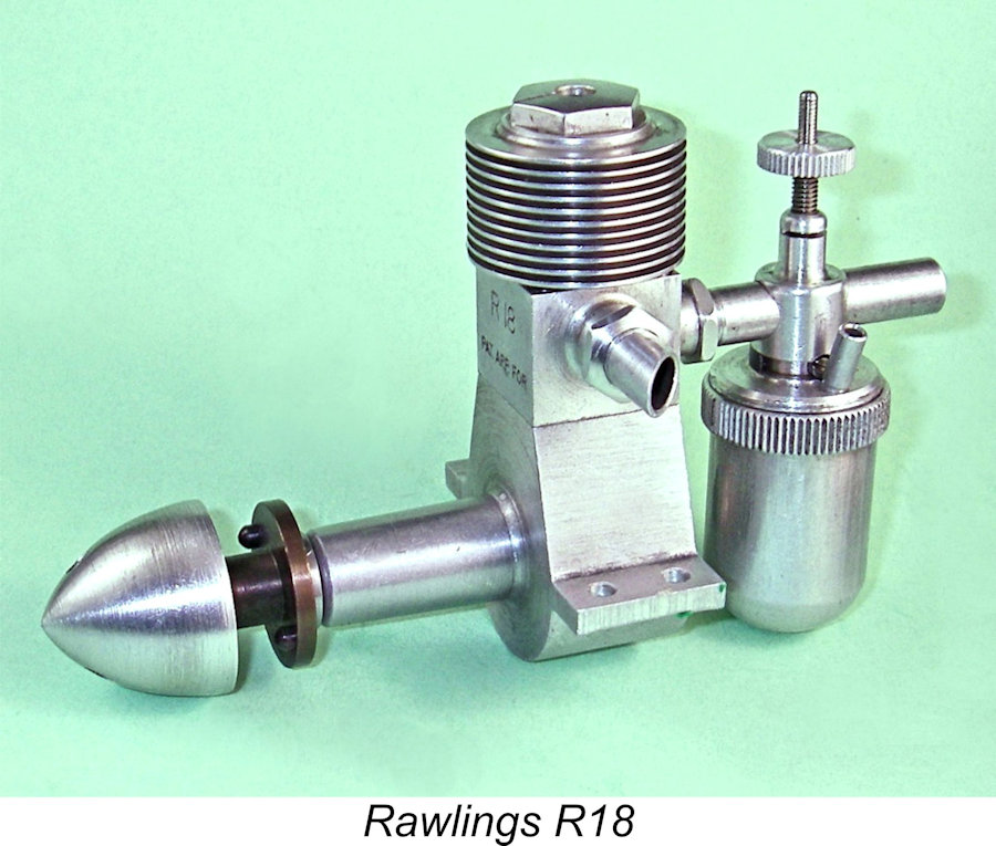
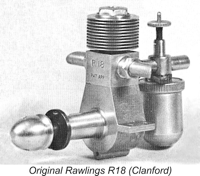
Kevin Richards pointed out a feature of the original R18 which had escaped my notice. This is the presence on the original units of a fore-and aft lug cast at the bottom of the case which was drilled all the way through with a small-diameter hole. Kevin was told that this was for a crankcase bleed off cut-out which was not implemented as it turned out. This lug is clearly visible in Clanford's illustration of an original R18 which appears in his "A-Z" book on page 165 and is reproduced here. If an example of the R18 lacks this lug, it's a Clanford repro. Having clarified the extent of Mike Clanford's involvement with the Rawlings engines, it's time to turn our attention to the all-important issue of the engines' levels of performance. Unfortunately, we'll have to rely on data extracted from a few Clanford reproductions rather than the mega-rare genuine articles. However, those examples should provide a reasonably close approximation of the performance to be expected from original examples. The Rawlings Diesels – Performance Based upon information supplied to him directly by George Rawlings, Fisher stated that every Rawlings engine was “extensively factory bench-tested” prior to dispatch. No R30 apparently left the works giving less than 44 oz static thrust, while many examples gave up to 48 oz. The manufacturer reportedly claimed that the R30 developed 0·27 bhp at 7,500-8,000 RPM, a very high output from a plain-bearing side-port 3.14 cc diesel for 1948, especially considering the relatively modest peaking speed. Some very serious torque development was clearly implied! Another factory test was to check that the R30 would achieve a minimum of 7,500 rpm on a 12x5 propeller. The smaller R18 was apparently factory-tested to reach a minimum of 7,500 rpm with a 10x5 airscrew. The minimum acceptable static thrust figure in this instance was 26 oz. Fisher didn’t report a factory power claim for this model. However, on a pro rata displacement basis, we might expect a claim of around 0.15 BHP @ 8,000 RPM for this model, assuming a near-identical specific output figure.
Richard Jackson ran a condensed bench test on his un-numbered Clanford-assembled example of the R30. For this test, he used an 11x6 plastic prop, which was the closest thing that he had to the recommended 12x5. He tried the engine on standard model diesel fuel (equal parts ether/kerosene/castor oil) – perhaps a hotter-running brew than that recommended by the manufacturers, but far kinder to the engine in terms of its oil content. Most classic sideport diesels run just fine on such a mixture. A problem which presented itself immediately was the fact that the cooling jacket ran out of thread before the compression ratio was sufficiently high for a start to be achieved using the above fuel mixture. In order to get sufficient compression to run the engine, it was necessary to insert a .030 in. thick spacer above the contra piston. This issue is presumably confined to the Clanford-assembled examples, since the factory-produced models could never have passed their running test in such a condition. With this spacer in place, the engine was given three or four choked turns with the needle valve open three turns, after which the compression was gradually increased until it “popped”. The compression was then increased another quarter turn, after which the engine started immediately. Following the usual adjustments, it was soon running evenly and well. Interestingly enough, the contra-piston remained free to move both hot and cold. Richard measured 6,500 RPM on the 11x6 prop. If that prop was an APC 11x6, the implied output would have been in the order of 0.156 BHP at that speed. This figure seems low by downward extrapolation from the manufacturer’s claimed output of 0.27 BHP @ 7,500-8,000 RPM, but it still represents a pretty good performance from a side-port diesel of this displacement. For comparison, my best example of the contemporary Allbon 2.8 (admittedly having a 10% lower displacement) only managed 6,100 RPM on that prop. Moreover, Richard noted that his R30 seemed to be running quite hot, discouraging him from going after the very best figure which the engine had to give on that prop. There’s little doubt that it had the potential to do a bit better once fully settled down.
Turning now to the smaller R18 model, Richard’s ex-Clanford example was New-in-Box, making him reluctant to run it at all. This left it down to me to give the R18 a try. My example too is a New-in-Box Clanford reproduction – definitely not the example formerly owned by Richard, based on the visible witness marks on the respective boxes. Regardless, I didn’t feel myself to be under the same compulsion to maintain the engine’s “unrun” state as Richard had done. Before any testing could commence, one issue had to be resolved. This was the fact that the end-float on the crankshaft assembly was way too large - the space between the rear of the prop driver and Starting and running the Rawlings in this condition would send fine metal particles through the engine, to the great detriment of its working life. The fixes were either to cut the female taper in the prop driver deeper or to make a steel spacer ring of the appropriate thickness. Not having a taper reamer of the correct angle, I adopted the second approach, making a steel spacer ring which eliminated almost all of the end-float. This fitting is clearly visible in the side view of the engine which appears above at the left. With this issue having been attended to, into the test stand went the Rawlings R18! Not having a 10x5 airscrew handy, I decided to try a Zinger 11x4 wood prop. I had no intention of putting this LNIB example through a full test, since that would require running it in - a pointless exercise since I was not planning to fly the engine. I just wanted to experience and report on its handling and running qualities.
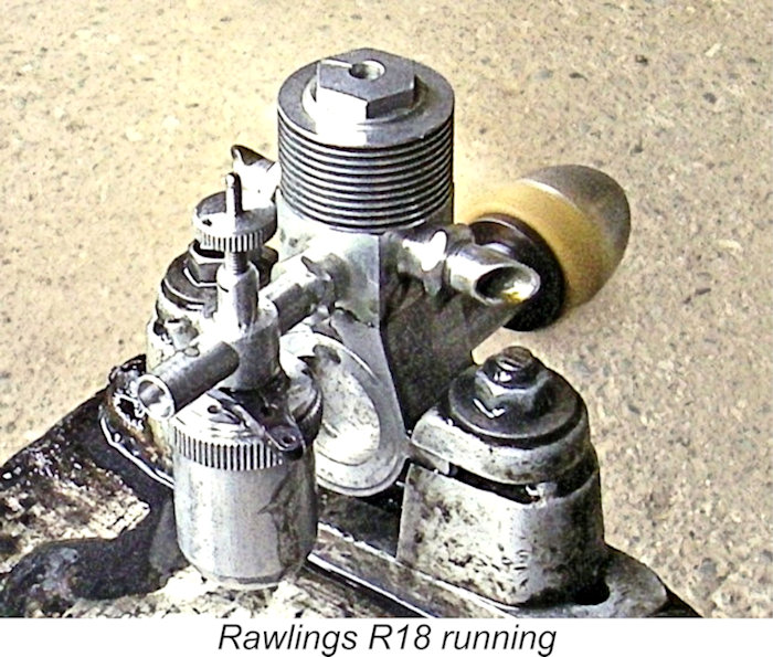
The engine felt superb when flicked over in the test stand. I anticipated no difficulty in getting it going. Alas for fond hopes - after applying a few choked flicks and a small exhaust prime, I flicked energetically with not so much as a pop! I increased compression, finding that the rotating jacket system worked very smoothly, but still to no avail. Eventually I "ran out of road" when the top of the contra-piston was level with the top of the liner, making further compression increases impossible. I got around this issue by installing a 0.020 in. thick washer of suitable dimensions on top of the contra-piston. This allowed the rotating jacket to push the contra-piston further down into the bore. A further small compression increase with the washer installed produced a firing stroke, after which a start was soon achieved. It's interesting to note that Richard Jackson had encountered exactly the same issue with his tested example of the Rawlings R30, leading one to the conclusion that Mike Clanford's engine-building assistants failed to replicate the compression control geometry precisely.
Be that as it may, the engine gave no further trouble when it came to starting. I learned quite quickly that it was very easy to flood the crankcase through excessive choking or over-enthusiastic port priming. The best approach was found to be to fill the tank, apply no more that two choked flicks, administer a small "dry" exhaust prime (exhaust port closed) and then get stuck in. This approach never failed to result in a very prompt start. Even though I wasn't planning to subject the engine to a complete break-in, I thought it wise to give it a little easy running time to settle it down. I therefore put 4 tanks of fuel though it, keeping it rich and at the lower limit of compression. The engine ran for over 2 minutes on a full tank. I tried the cut-out, finding that it worked perfectly. For the next run, I increased the compression slightly and then started the engine on the previously-established rich setting (1½ turns). After letting it warm up, I leaned out the mixture. The engine ran absolutely smoothly in this condition, with vibration levels which seemed to be well within manageable limits despite the lack of crankshaft counterbalance. It got the 11x4 Zinger prop up to 6,700 RPM - around 0.118 BHP at that speed. I tried a second run, achieving exactly the same speed. If the manufacturer's claims are any guide, there should be more to come at a slightly higher speed. As stated earlier, we might expect a peak output of around 0.15 BHP @ 8,000 RPM. My figure for the 11x4 is not inconsistent with such an expectation, especially considering that the engine is not yet run in. The engine might do a little better after a full break-in, but not by very much in my view. In any case, I'd done what I set out to do - demonstrated that the R18 was a beautifully-made, fine-handling and smooth-running engine which was well-placed in the performance mix with its 2 cc sideport diesel contemporaries, notably the slightly higher-displacement E.D. Comp Special. Its main performance nemesis would have been the contemporary Elfin 1.8, which would doubtless have over-shadowed it in the contest arena. However, it would have made a really excellent powerplant for mid-sized free-flight sport and scale models. Allowing for airborne pickup, the 11x4 prop appears to be an ideal size for free-flight use. Summary and Conclusion
As if this wasn’t enough, the very high standards to which the engines were manufactured dictated that they be retailed at relatively high prices if a rational profit margin was to be maintained. Upon its mid-1948 introduction, the R30 retailed at £6 5s Od (£6·25), while the Allbon 2.8 sold at the same time for only £4 16s 0d. (£4.80). The R18 was more competitively priced at £4 17s 6d (£4·87), thus matching the contemporary 2 cc E.D. Comp Special but exceeding the £4 price tag of the excellent Elfin 1.8 by a potentially significant margin. The R18 was well ahead of both of its rivals in terms of quality, but the manufacturing effort required to achieve that status must have made the R18 a rather uncompetitive product from the manufacturer’s standpoint in terms of profit margin.
Add in the fact that the engines’ outstanding quality and design complexity required a level of manufacturing effort which prevented them from being offered at competitive prices if an acceptable profit margin was to be maintained, and it becomes clear that they never stood a chance of achieving any real commercial success. The threatened advent of purchase tax was the final straw - the looming threat prompted the Rawlings company to end model engine production during 1949, turning its capabilities towards other more profitable business lines. The marketplace failure of their model engine range by no means represented a fatal blow to the Rawlings company. On the contrary, Fisher reported that George Rawlings and his son Vincent were still running the company in 1977, 28 years after they had produced their last model engine! They were no longer connected with the model trade, to the lasting detriment of the latter. We must be glad that they stayed connected with that trade long enough to leave a legacy of some highly original model diesel engines of unusual quality! __________________________ Article © Adrian C. Duncan, Coquitlam, British Columbia, Canada First published May 2025 Revised edition published June 2025 - the Clanford connection
|
 In this article I’ll share a look at a very short-lived and somewhat exclusive range of high-quality model diesels from early post-WW2 England. I’ll be examining the very rare Rawlings diesels from Kenilworth, Warwickshire in the English Midlands.
 It’s very likely that someone associated with the company was a model aircraft enthusiast who drew their attention to this potential post-war outlet for their capabilities. The result of any such deliberations was the mid-1948 appearance of two superbly-crafted model diesels - the R18 of 1.81 cc displacement and the 3.14 cc R30 model. Both were sideport diesels which were built to a common design of unusual complexity.
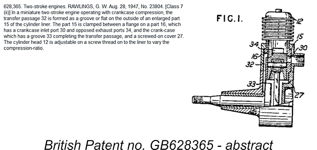 British Patent no. GB628365
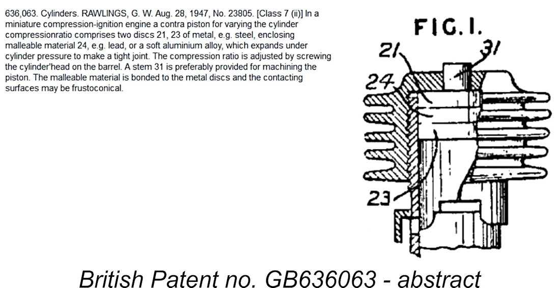 British Patent no. GB636063
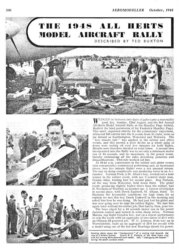
 The larger R30 faced extremely stiff competition of its own in the shape of the
 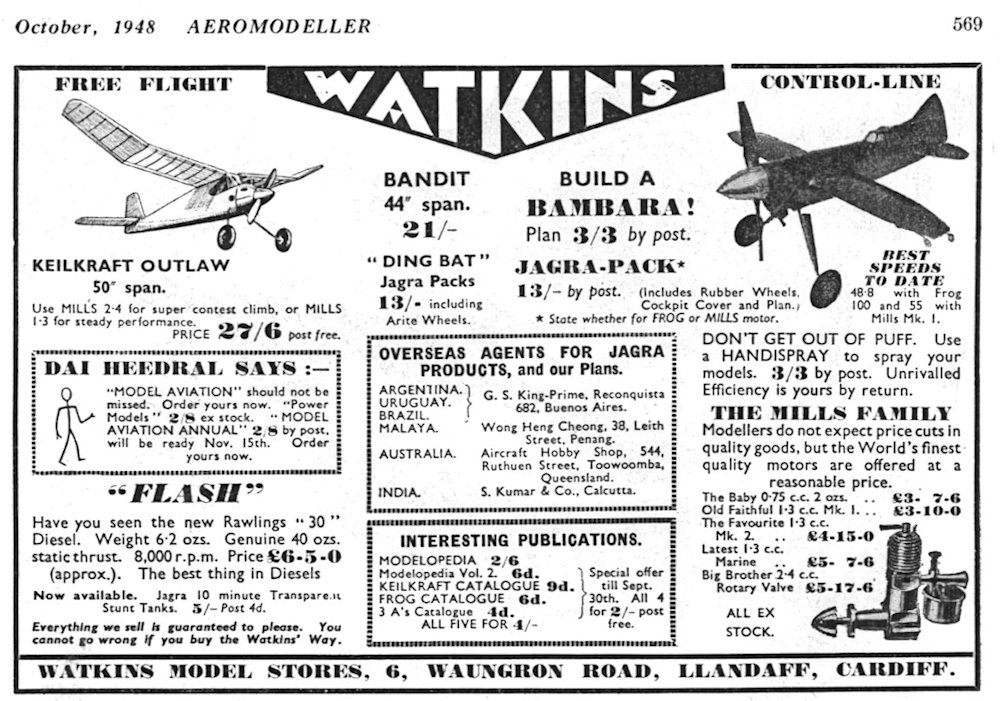 Three of these listings came from Watkins Model Stores in Cardiff, who were the main promoters of the almost equally obscure
 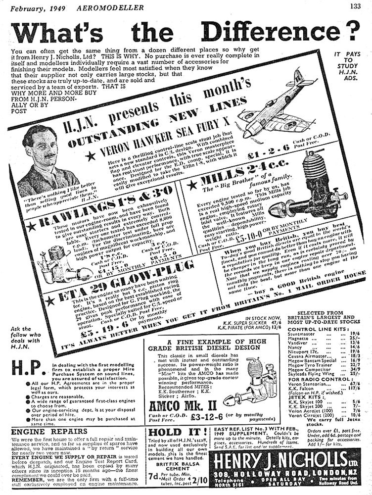 Five ads were placed in “Aeromodeller” by Watkins’ rival Cardiff model shop Bud Morgan. Henry J. Nicholls included the engines in two advertisements, his initial placement of February 1949 (left) including a highly laudatory endorsement of the Rawlings diesels, characterizing them as “engines of magnificent workmanship and high power output for capacity”. He was then advertising the R18 at a slightly reduced price of £4 15s 0d. (£4.75), although the price of the R30 remained unchanged at £6 5s Od (£6·25). Nicholls’ second and final placement mentioning the Rawlings engines appeared much later in October 1949.
 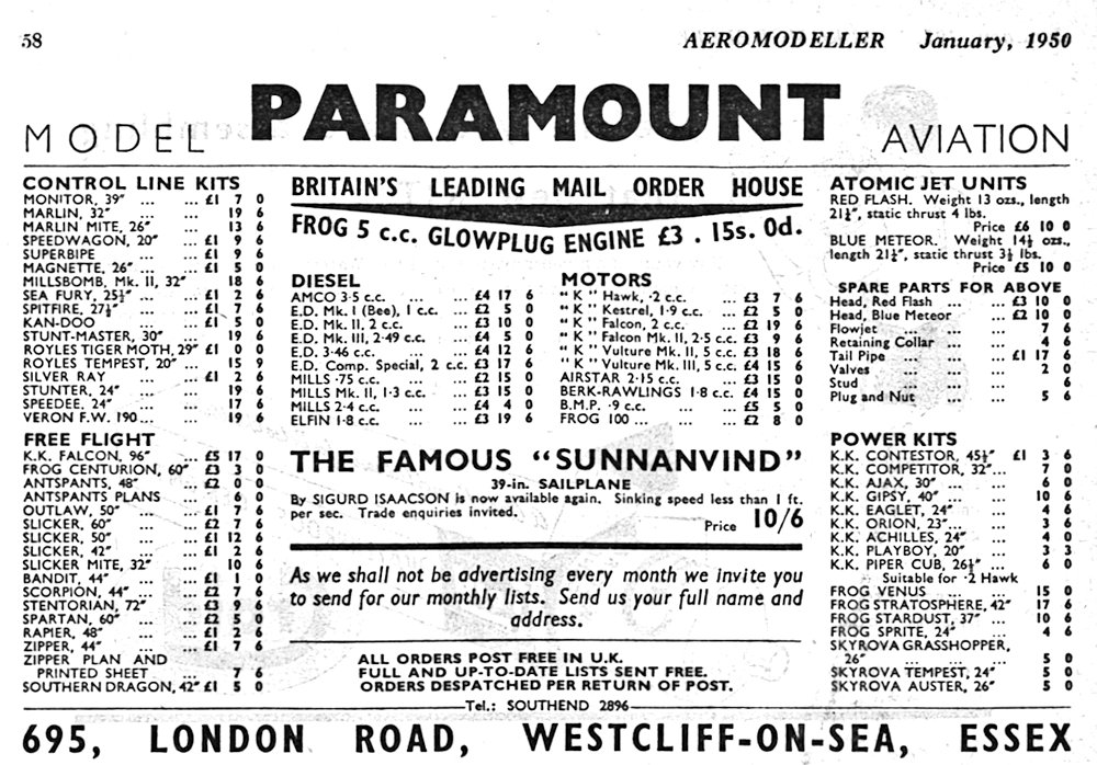 1949. Thereafter, no further Paramount ads appeared until January 1950, when what turned out to be the final advertising mention of the Rawlings engines appeared seemingly somewhat belatedly following a five-month hiatus. This advertisement is reproduced at the right.
 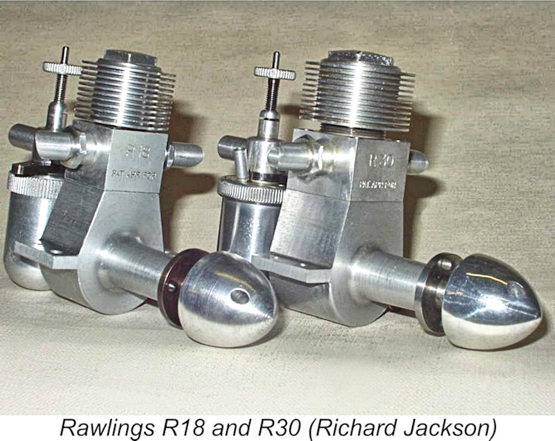 The design similarities between the Rawlings R18 and R30 models are so great that to describe one is virtually to describe the other. I’ll proceed to do so forthwith, noting any points of difference along the way.
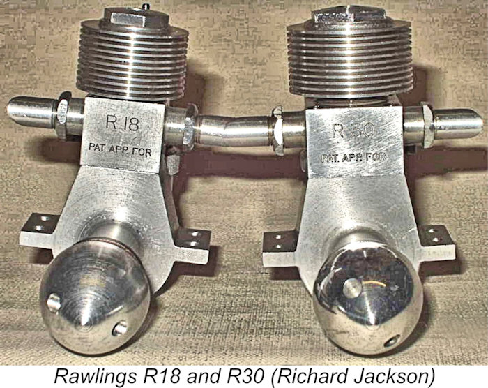 The main crankcases of both units were topped by a separate "port block" which was machined from aluminium alloy bar stock and secured to the main case by four 6BA cap screws with turned-down heads countersunk into its top face. Above the beam mounting lugs, the case of the R30 was necessarily more massive than that of the R18, as it had to be to accommodate the larger port block required to enclose the greater external diameter of the R30 cylinder. The port block incorporated both the induction port at the rear and the two exhaust openings, one on each side. The latter openings were equipped with screw-in exhaust stubs which were secured with lock nuts.
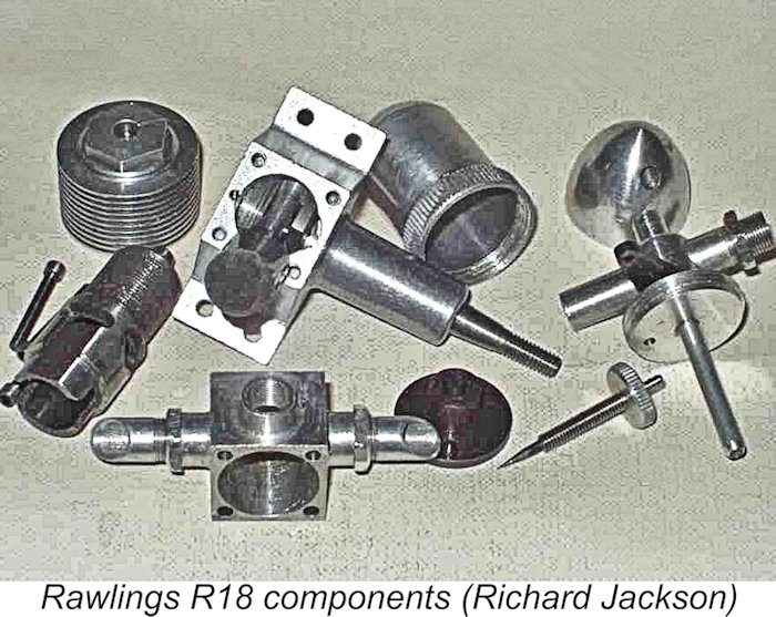 gasket. An internal shelf at the top of the alloy port block bore upon the upper lip of the liner’s port belt, holding it in place. The cylinder ports were oval-shaped, being quite generous in size.
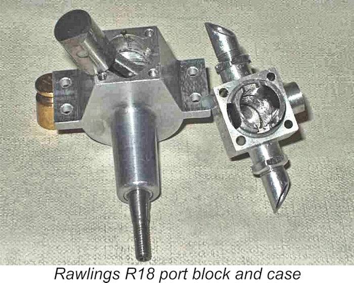
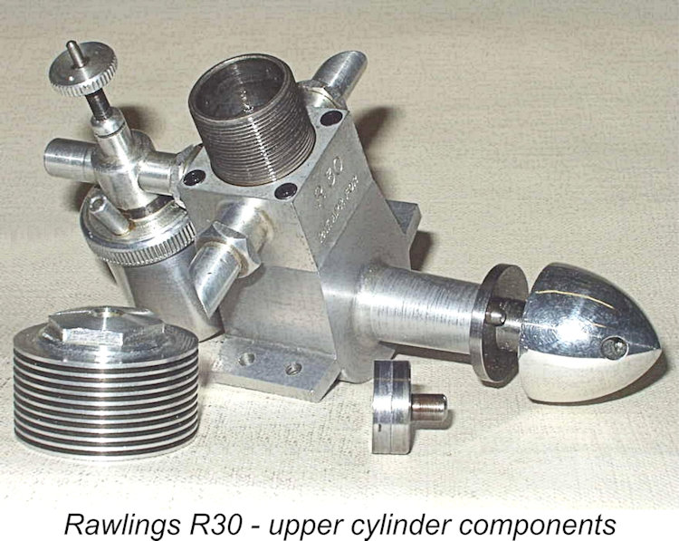 With the cylinder installed in the case and secured by the port block, an externally-threaded portion of the upper cylinder liner was left exposed. This very fine external thread accommodated a screw-on cooling jacket which was very accurately fitted to the exposed male thread on the external upper cylinder. This jacket incorporated the head in unit.
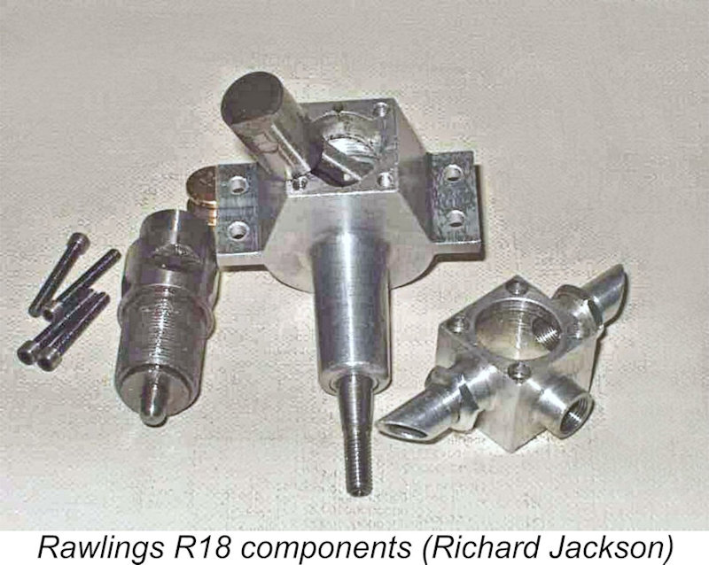
 The piston drove the crankshaft through a substantial conrod which was machined from aluminium alloy bar stock. The crankshaft was a one-piece component machined from 70-ton Nitralloy steel. It featured a somewhat primitive crankweb having a rectangular shape and incorporating no counterbalance - not the best-possible design. The main journal ran in what appears to be a cast iron bushing. A groove was cut into the thrust face to encourage the supply of lubricant to the shaft.
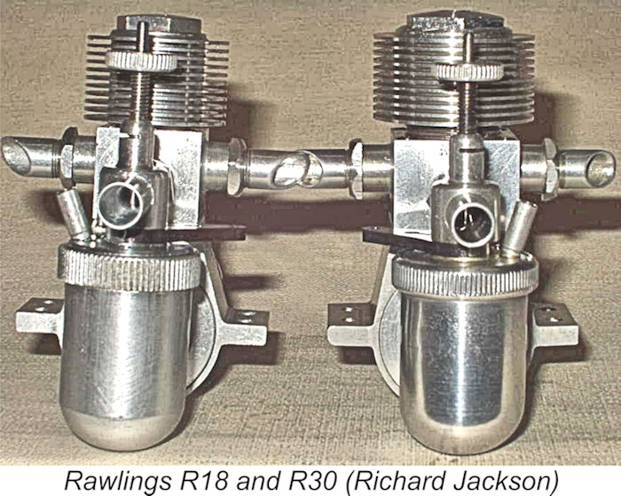 The screw-in venturi was secured in the desired orientation by a lock-nut. Both the venturi and tank top were machined from aluminium alloy. The large spun-aluminium fuel tank was retained by a coarse-threaded knurled ring. The fuel cut-out lever was made of blued steel. This cut-out operated as an air-bleed unit, admitting air to the engines's fuel delivery pipe to destroy its suction. Oddly enough, the cut-out on my example of the R18 works in the opposite manner to that indicated in the instructions - it is in running position when pulled back and stops the engine by being pushed forward. Not a convenient arrangement for activation by a timer! Read on for the explanation of this anomaly ...........
 It is these ex-Clanford examples which constitute the relatively numerous body of un-numbered Rawlings engines. Indeed, the majority of Rawlings engines encountered today are undoubledly Clanford reproductions rather than originals. Basically, if it doesn't have a serial number, it's a Clanford repro! My un-numbered R18 is clearly one of these latter-day examples. It's a very nice engine, as we shall see, but it wasn't assembled in the Rawlings workshop. The latter comment almost certainly explains the fact that the tank top on my engine is installed "backwards" with the cut-out lever on the right-hand side and functioning in reverse!
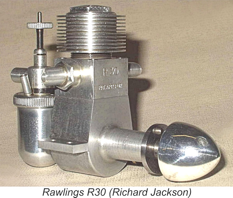 The instructions recommended a fuel consisting of 6 parts ether, 3 parts road diesel and 2 parts castor oil. The 55% ether content was entirely appropriate for a low-speed engine which was expected to operate as a
 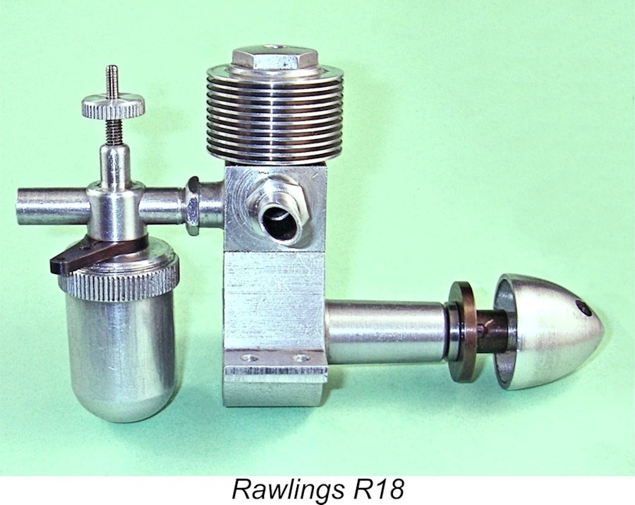 Richard’s overall comment was that the Rawlings R30 was a very nice-handling and smooth-running engine which was easy to start and not at all fussy regarding the control adjustments. He found that at the running compression setting, the contra piston still protruded by some 1/16 in. above the top of the liner, indicating that there was still some headroom available with that setting.
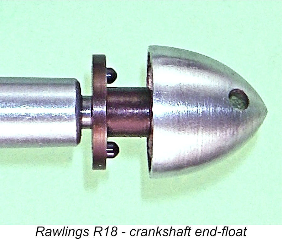
 The fuel used was my standard test brew containing 35% ether, 35% kerosene and 30% castor oil, with a small dose of ignition improver added. I was careful to provide myself with a ring spanner of the appropriate size for making compression adjustments – no sense risking any marring of the cylinder head on this LNIB example! The pristine mounting lugs were protected by small wrappings of non-metallic gasket material.
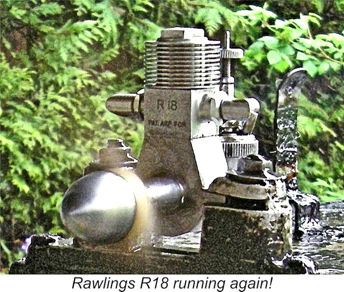
 Looking at their relative complexity as well as the very high standards to which they were manufactured, the Rawlings engines must have been very expensive items to produce. Moreover, they don’t appear to have enjoyed any performance advantages over their competitors despite all that quality and complexity. They would certainly not have taken kindly to the ministrations of the average ham-fisted aeromodelling “compulsive tinkerer” with his Meccano screwdriver and worn-out pliers (I know what I’m talking about, ‘cuz I wuz one once!!)! The slightest damage to the un-gasketed joint faces in the vicinity of the bypass would have compromised the engines’ running capabilities quite severely.
 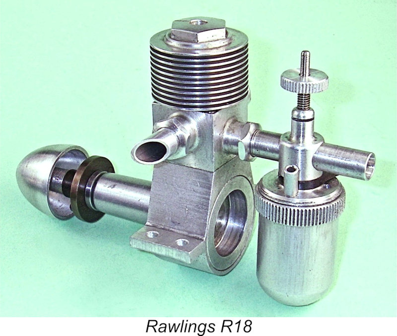 The plain fact is that for all their quite legitimate claims to outstanding quality and design originality, the Rawlings engines were already outdated in performance terms at the time of their initial appearance. The ever-increasing popularity of control-line at the time wouldn’t have done anything to help – lower-priced engines which were superior to the Rawlings for that purpose were appearing all the time by then.
 | |