
|
|
Welsh Enigma - the Dyne engines
Frankly, my main hope here is that the appearance of this article will inspire someone’s son, grandson or nephew who is “in the know” to come forward and set the record straight! Not such a far-fetched scenario - it’s happened before ……… Before getting started on this article, it’s both my duty and pleasure to acknowledge the immense debt of gratitude that I owe to my good friend Maris Dislers. Maris was kind enough to troll through his extensive collection of old “Aeromodeller” magazines to obtain scans of a significant number of advertisements for the Dyne engines as well as their only test appearance in the modelling media of the day. I couldn’t have got anywhere in researching this article without this assistance. Thanks, mate!!
It would also be quite impossible to write authoritatively about any pioneering British model engine marque without drawing upon the immense knowledge of those early ranges held by my valued friend and colleague Kevin Richards. Kevin is best known as the world’s leading expert on the E.D. range, about which he is in the process of writing a long-awaited book which will doubtless represent the last word on that subject. However, along the way Kevin has accumulated a wealth of information about other pioneering British model engine ranges, which he has always been happy to place at my disposal. The Dyne study was no exception – I would have got nowhere without Kevin’s help. Apart from supplying some insightful comments along with a number of images, he even went so far as to make an actual example of the Dyne 3 cc diesel available to me for direct study and testing. Thanks, my friend!! OK, down to business!! We’ll begin by looking at the Cardiff-based company which promoted the Dyne range. The Distributor – Watkins Model Stores As far as the British modelling public was concerned, the Dyne model engine range appeared out of nowhere in the early part of 1947, being promoted exclusively by Watkins Model Stores of 6 Waungron Road, Llandaff, Cardiff. According to their later advertising, the Cardiff-based Watkins model supply business was established by H. J. Watkins in 1936. In a brief article which appeared in the July 2012 issue of SAM35 Speaks, Ron Raddon recalled that the Watkins model supply business was run out of premises at the rear of the family ironmongery business. This makes it appear likely that the Watkins model supply venture was an add-on to a previously-established business in another field. My sincere thanks to Ken Smith for drawing my attention to this article. Ron Raddon had been a customer of Watkins Stores while stationed at nearby RAF St. Athan during 1947/48. He recalled that small batches of the Dyne engines were delivered to the store from time to time, but had no knowledge of their origin beyond the presumption that the source was local. To put readers in touch with a far simpler and more accommodating time, Ron also recalled that the development of the estate which now surrounds the Waungron Road location was still underway as of 1947/48. The nearby street intersection remained unobstructed either by structures or significant amounts of traffic, hence being used by the company staff for the flight testing of new control-line models and engines! Try that on for size today ................
As far as I can discover, the Watkins venture began as a strictly local business, only going nation-wide in terms of advertising immediately following the conclusion of WW2. By September 1945 Watkins was taking out low-budget “business card” advertisements in “Aeromodeller” magazine, presumaby to test the effectiveness of national advertising. The results must have been encouraging, because these advertising placements soon grew both in size and scope.
As the business expanded during the early post-war period, owner H. J. Watkins was joined by Jack Watson and Graham Jones. Post-war advertisements confirm that Watkins personally designed a number of the models which were sold through the store, while a number of other “house” designs were produced by Graham Jones. The firm offered a world-wide mail order service, attracting satisfied customers from such diverse and distant locations as Malaya and Texas if their advertising is to be believed. For 1947 they published a reportedly very informative 64 page "Watkins Handbook" which included information relating to the full scope of aeromodelling products which they sold. This was replaced in early 1948 by an expanded 72-page catalogue/handbook called "Modelopedia", of which Volume 1 (Power) appeared in February of that year. This catalogue was reportedly one of the most comprehensive such documents offered by any British retail outlet. Beginning in early 1948, Watkins began applying the trade-name “Jagra” to many of their commercial offerings. This name of course derives from the names of JAck Watson and GRAham Jones, implying that these two gentlement may actually have taken over the business from H. J. Watkins at around this time. The most notable Jagra products were the company's Jagra model engine speed control valves, their Jagra fuel cut-outs for model diesels, their Jagra “Visi-Flo” plastic control line stunt tanks and their Jagra model aircraft plans. They also offered “Jagra packs” which were assemblages of their plans together with all materials and supplies needed to build the models, sold as a single package – the next best thing to buying a kit. The Jagra name also became attached to some of the Dyne engines, as we shall see later.
Watkins’ May 1947 advertisement reflected this approach, advising the prospective buyer to “beware of the many dud engines now flooding the market” (without of course naming the offenders!) and offering to provide free advice to customers in this regard. They specifically stated in that advertisement that they only sold engines which had passed their own bench and flight tests, also offering a “satisfaction guaranteed or money back” policy which superseded any warranty which the manufacturer might have offered. In September of 1947 they claimed to have tested both British and foreign engines, making their resulting direct experience freely available to their customers. All of this makes it clear that Watkins had a very strong commitment to quality and customer satisfaction when it came to the model engines that they sold. This being the case, the May 1947 adoption of the Dyne engines as a “house brand” by the Watkins firm must surely be seen as a direct reflection of the quality which they attributed to that range. We may confidently assume that Watkins had followed their stated policy by testing the Dyne engines thoroughly and satisfying themselves of the engines’ quality before agreeing to take them on. Whatever the facts, the outcome of any testing which may have been undertaken was the fact that beginning in May 1947 the Dyne engines were nationally advertised and marketed exclusively through Watkins’ Cardiff shop. Genesis of the Dyne Range A number of comments made by Watkins in their promotional materials strongly suggest that the engines were hand-built by a single individual working to toolroom standards of precision. As far as I'm aware, the sole contemporary published attribution of the Dyne engines to a specific maker is to be found in the article by D. J. Laidlaw-Dickson entitled “British Commercial Diesel Engines - Spring 1948” which appeared in the March/April issue of” Model Mechanic” magazine. In that article, the Dyne manufacturer is recorded as being C. P. Dyne Ltd. of 178 Falcon Road, Clapham Junction, London. This identification has been accepted without question by later writers.
The company continued to advertise throughout the WW2 years. During that period, the number of locations mentioned in the advertisements decreased, while the cited Falcon Road adresses changed, eventually settling on a single location at 178 Falcon Road. Following the war, the focus of C. P. Dyne became centred upon the marketing of model plans under the Dewfly Model Aircraft brand name. The first advertisement using that designation appeared in the November 1945 issue of "Aeromodeller", as reproduced above. Dyne placed further advertisements referring to the Dewfly name from January 1946 through to October 1946 inclusive. Thereafter, there was a hiatus in national advertising until June 1951, when C. P. Dyne advertisements resumed in the low-budget business-card Model Shop Directory feature in "Model Aircraft", continuing until February 1957. The business remained located at Falcon Road throughout, implying that it had continued in operation at that location throughout the period of advertising hiatus from late 1946 to mid 1951.
At my request, Gordon Beeby went through his collection of "Aeromodeller" magazines from 1946 through 1950. The only Dyne advertisements by businesses other than Watkins which he was able to find were a June 1947 placement by Experimental & Model Co. (EMCO) of Coventry, which simply included the Dyne name among the engine ranges offered without any details, and an October 1948 offering of the Dyne 4 cc petrol unit by Arthur Mullet of Brighton at a price of £5 18s 6d (£5.93). The advertisement by EMCO was their one and only placement in "Aeromodeller" during this period, while the sole mention of the Dyne sparkie by Mullet came near the end of Dyne production, perhaps indicating an attempt by someone to move slow-selling merchandise. Consequently, it appears to be beyond argument that the Dyne range was in effect marketed exclusively by the Watkins firm of Cardiff. Given this fact, it would appear to be a logical deduction that the engines most likely originated in that area. This is consistent with Ron Raddon's previously-noted recollection of small batches of Dyne engines being delivered periodically to the Watkins shop. A London manufacturer would surely have found some means of marketing his products in the London area, which offered far broader marketing prospects. If the manufacturing took place at the cited address of C. P. Dyne's shop at Clapham Junction, engines would have had to be sent clear across Britain to reach what appears to have been their sole distribution point in a relatively minor market area. To me, this makes no sense at all!
And yet the Dyne engines were completely ignored by Sparey in his May 1947 "Aeromodeller" summary of then-current British diesels despite the fact that the Dyne 3 cc diesel model (see below) was undoubtedly in existence by that time. I can find no logical explanation for the omission of the range from Sparey's 1947 article other than to suggest that he wasn't aware of their existence at that time. Sparey did become aware of the Dyne engines later, since he went so far as to publish a test of the Dyne 3 cc Mk. 3 diesel in October 1948. Sadly, he did so without actually naming the manufacturer, merely citing Watkins as the distributor and making no mention of C. P. Dyne. If the manufacturer had in fact been C. P. Dyne, Sparey would undoubtedly have known and would surely have mentioned the fact. In the end, the identification of C. P. Dyne as the manufacturer of the Dyne engines seems to have been based entirely upon the assumption that the name of the Dyne model engine range must be that of the designer/manufacturer. Gordon Beeby has pointed out quite reasonably that this is by no means a logical assumption. After all, the term "dyne" is actually the name of a unit of force, serving as the root of energy-implying terms like "dynamic", "dynamite" and "dynamo". This would make it an entirely logical name for a model engine maker to apply to his products. He may even have been inspired by the name "Dyno" attached to one of the best-known diesels of the pioneering era, simply changing one letter to avoid infringement while suggesting that his engines exhibited similar qualities. There's absolutely no certainty that the engines were produced by an individual named Dyne - FROG engines were certainly not designed by an amphibian, after all! Taking all of the above points into account, I'm firmly of the opinion that the coincidence of the names of model shop owner C. P. Dyne and the Dyne model engine range is just that - a coincidence. It seems likely that Laidlaw-Dickson made an incorrect assumption based solely upon this coincidence of names, and subsequent writers have simply accepted his identification without stopping to consider all of the evidence, thus perpetuating what I believe to have been an error. There's been far too much of that in the past! In an article by John Goodall which appeared in the May 1996 issue of the very informative but sadly now defunct "Model Engine World" (MEW) magazine (primarily focusing upon the Dyne 6 cc spark ignition model), John referred to an earlier article on British spark ignition engines by Gordon Counsell which had appeared in SAM 35 Yearbook no. 6. During the writing of his own article, John had contacted Gordon, who expressed his personal opinion that the Dyne engines were made by Atlas Motors of Dunstable in Bedfordshire. However, no evidence for this belief was presented. In the absence of any further evidence, we have to leave this issue there .............
When considering the question of the true introductory date of the Dyne engines, it’s necessary to note that the diesel models were not mentioned either in D. J. Laidlaw-Dickson’s late 1946 book "Model Diesels" or in the September 1947 first edition of Col. C E. Bowden’s book "Diesel Model Engines". As previously noted, they were also omitted from the April 1947 “British Diesel Summary” by Lawrence Sparey, writing as “Artifex” in keeping with the common practise at the time of using a pseudonym. This summary appeared in the same May 1947 issue of “Aeromodeller” in which the Dyne engines (including the 3 cc diesel) were first advertised by Watkins. This of course does not necessarily mean that the Dyne engines were not in existence as of the publication dates of those pioneering references – merely that they had not come to the attention of the authors at their respective times of writing. A geographically-constrained South Wales origin for the range would amply explain this. As noted earlier, Watkins only began to advertise the Dyne range nationally in May 1947, long after the compilation of Laidlaw-Dickson’s first edition and concurrently with the appearance of the summary by “Artifex”, which must have been written a month or so earlier to meet the editorial deadline. Hence neither of those two writers could have been aware of the existence of the Dyne diesel on the basis of any national advertising. The 3 cc diesel model was certainly in existence (or at least being advertised) prior to Col. Bowden’s first edition being sent to the printers, but his omission of any mention of it merely indicates that he had not then become aware of it. Of course, he could only have done so if he happened to read a Watkins advertisement during the period when he was finalizing his text. If the hypothesis (which is all that it is) of an early introductory date for the range has any factual basis, we would have to assume that the Dyne engines were originally sold by the manufacturer directly to customers in his local area, hence not being nationally advertised at that stage. This is a perfectly rational hypothesis in the context of the early post-war British model engine market, and one for which there were many precedents.
In response to this demand, a significant number of small-scale “cottage industry” model engine manufacturers quickly began to appear in Britain, some of them working quite literally in the proverbial garden shed (or cow-shed in the case of the makers of the Clan engines from Fife in Scotland!). In addition to Clan, the names of Healy, Reeves, M.E.C., Ace, Comet, E.P.C., M.S., Leesil, Owat, Wilsco and Milford spring immediately to mind, and there were others. Indeed, there were almost certainly a number of such small-scale “artisan” operations whose names are now lost to us. I Another factor which argues strongly for an "artisan" origin is the very clear evidence on my own examples of a good deal of individual hand-work in their manufacture. The gravity die-cast crankcases and machined bronze con-rods appear to have been considerably "cleaned up" by hand, while the engines in general appear to have been manufactured using a rather limited machine tool inventory. The standards of fit and finish are outstanding where it counts, but little effort has been made to "pretty up" the engines' external appearance. All of this is typical of individually-built motors having a small-scale "model engineering" production background. Based on the range of known models which emanated from whichever workshop produced the Dyne engines, it appears to me to be very likely that the range actually had its genesis at some point during 1946. With a presently confirmed total of no fewer than ten distinct models (three diesel, six spark ignition and one glow-plug), it seems highly improbable that a significant proportion of these could have been developed and produced by a small-scale artisan manufacturer within a relatively short space of time in 1947. It’s perfectly possible and even likely that the Dyne engines were in small-scale individual production for local direct marketing well before May 1947. Another factor which argues strongly for a somewhat earlier date for the establishment of the range is the marked preponderance of the aforementioned spark ignition models. Although a number of established sparkers remained in production as of mid 1947, the era of the diesel had well and truly arrived in Britain by that time. Consequently, few if any new general-purpose spark ignition designs were appearing on the market by that date. It seems far more likely that the manufacture of the Dyne engines actually commenced somewhat earlier at a time when spark ignition was still in mainstream use. Viewed in this context, it appears to me to be highly improbable that the entire range of early spark ignition models that are known to exist could ever have been in simultaneous production by an artisan manufacturer at any one time prior to early 1947. It actually seems far more probable that the unknown manufacturer got his start in 1946 by making spark ignition engines to a basic design in whatever displacement(s) a customer ordered. In other words, he was making model engines to custom order, probably one at a time. This would explain the wide variety of early sparkers which are known to exist but which did not survive into the Watkins marketing era. Probably only a handful of each type were ever made (apart from the 3.8 cc model, which remained in production all along). If this was the case, the engines were presumably marketed locally direct from the manufacturer, with no national advertising. At this stage, demand from the local aeromodelling community might well have equaled or even exceeded the production capacity of a one-man artisan manufacturing operation, especially if the engines established a good word-of-mouth reputation within that community on the basis of their performance and dependability in the field. However, this would not have lasted for ever. If the engines were sub-standard, their reputation would spread quickly among the local aeromodelling community, resulting in the evaporation of demand in short order. By contrast, if the engines were serviceable units which did not require frequent replacement in use, owners would just keep on using them without having to consider buying replacements. Either way, local demand would eventually be satisfied, making it necessary to explore ways and means of expanding the marketing scope of the range. The involvement of the nationally-advertised Watkins supply house would have represented just such an initiative. Reviewing all of the above discussion, I personally believe it to be more probable than not that the Dyne engines were individually hand-built by an experienced model engineering type working more or less alone in his own small-scale workshop. This would explain the high standard of precision exhibited by these engines; the considerable evidence of individual hand-finishing; and the seemingly minimal production rate. Furthermore, in view of a statement by Watkins in "Modelopedia" to the effect that the un-named maker of the Dyne engines had "over thirty years of tool-room experience behind him", it's pretty clear that he was a mature individual. This may even have been a form of retirement project for him. As an aside, it may be noted that the reference to thirty years of tool-room experience does not sound in the least like model shop owner C. P. Dyne! I also believe it to be more probable than not that the maker of the Dyne engines worked in or near Cardiff. As a small-scale manufacturer seeking a marketing partner, he would most logically attempt to develop such a relationship with a local firm. Indeed, it seems difficult to understand how or even why a small-scale artisan manufacturer working in either London or the English Midlands could have established such a close and exclusive relationship with the Cardiff-based Watkins firm. However, in the absence of any evidence one way or another, we have to leave the issue of the manufacturer's location in or near Cardiff as no more than a logical but unsubstantiated possibility. We’ll probably never know when or at whose instigation Watkins Stores first entered into discussions with the unknown maker of the Dyne engines with a view to becoming his exclusive national marketing agents. All we know for certain is that Watkins began to promote the range in its May 1947 advertising placement in “Aeromodeller”. Promotion of the Dyne Range by Watkins At the time when Watkins began to promote the Dyne range in their May 1947 “Aeromodeller” advertising placement, the only models offered were a 3 cc diesel and a 4 cc sparker. Since this issue of the magazine actually reached the news-stands in mid April, considerations of editorial lead time imply very clearly that these two models must have been at least developed, if not put into limited production, by early 1947 at the latest. The 5 cc car/boat sparker and 2 cc diesel model (see below) had yet to appear, while neither the 4 cc diesel mentioned by Mike Clanford in his 1987 "Pictorial A-Z of Vintage and Classic Model Airplane Engines" nor any of the other attested spark ignition models ever appeared at any time in Watkins’ advertising.
In terms of Watkins' quality expectations, a review of the list of recommended engines which appeared in their May 1947 advertisement along with the two Dyne models is quite revealing. Apart from the Dyne 4 cc petrol model and the Dyne 3 cc diesel, they were also listing the FROG 175, Majesco "45", Stentor 6 and Keil K6 sparkers as well as the B.M.P. 0.9 cc and 3.5 cc diesels together with the Owat 5 cc fixed-compression diesel, the then newly-introduced FROG 100, the Mills 1.3 and the 2 cc E.D. Comp Special. They claimed that all of these models had passed their own bench and flight tests, hence being recommendable to their customers. The inclusion of the Dyne engines in the above listing implies that in the minds of the Watkins management their serviceability at least matched that of the other featured models, all of which were certainly very acceptable units based on my own direct experience with them. Watkins clearly had great faith in the basic quality of the Dyne range. It's perfectly true that they may have been motivated at least in part by a desire to promote the "local product" (assuming a Cardiff location for the manufacturer), but even so their adoption of the range speaks eloquently for their view of its quality.
The marketing of an exclusive “house line” of model engines by an individual model shop was by no means an uncommon practise at the time. Perhaps the earliest such venture was that of the Caledonia Model Co. of 5 Pitt Street in Glasgow, Scotland, who began to promote their highly-regarded Clansman 5 cc diesel and Falcon 5 cc spark ignition unit in June 1946. Others soon followed suit - at about the same time that Watkins was preparing to market the Dyne range, a London model shop owner named Harry York, who operated a retail outlet called Model Aircraft Supplies Ltd. at 171 New Kent Road, London S.E.1., was in the process of introducing his London-made “house special” Ace 0.5 cc model, an account of which may be found elsewhere on the late Ron Chernich’s now-frozen but still invaluable “Model Engine News” (MEN) web-site. Harry York’s initiative in marketing the Ace 0.5 cc model through his store (it’s highly unlikely that he actually manufactured it) seems to have prompted several other London-based retail businesses to start thinking about getting into the game with their own “house” model engine designs. The long-established firm of Premier Aeromodel Supplies Ltd. of 2A Hornsey Rise, a little to the north of Islington, entered the model engine market in May 1948 with their ultra-lightweight and very compact M.E.C. 1.2 cc diesel offering which has been reviewed elsewhere on this website. Another London-based retail firm which elected to follow Harry York’s lead was the famous Gamages department store at 116-128 Holborn in Central London, which introduced the Comet 0.4 cc diesel as a house model in June 1948. This engine too is the subject of a separate article to be found on this website.
Finally, the Weston-Super-Mare retail outlet of Weston Model Aero Supplies jumped onto the “house range” bandwagon in March 1948 with their own range of Weston diesels in 0.25 cc, 3.5 cc and 5 cc displacements. Although a few engines were apparently manufactured (the 3.5 cc model was the subject of a June 1949 "Aeromodeller" test by Lawrence Sparey), this range was not a success, hence being withdrawn relatively early on. A focused article on the Weston model engine range may be found elsewhere on this website. Returning now to the Dyne story, the Dyne engines were regularly advertised by Watkins following their initial advertising appearance in May 1947, continuing to feature in Watkins advertisements right At the outset, the only models mentioned were the 3 cc diesel and 4 cc sparker. The early advertisements for the Dyne 3 cc diesel appear to have been placed more to generate interest than for any other reason, since the advertisements clearly imply that the Dyne 3 only entered series production in July 1947, finally being confirmed as being "now in stock" in September 1947. The September 1947 advertisement also mentioned that a Dyne 2 cc diesel model would be available “shortly”, although it did not appear in the October 1947 placement, which still only featured the 3 cc diesel and 4 cc sparker. However, the 2 cc diesel was listed as of December 1947 along with the other two models. Up to this point, the diesel illustrated in the advertisements appeared to be the Mk. 1 variant of the Dyne 3 – that version was specifically identified as being the illustrated model in Watkins’ January 1948 advertisement. January 1948 saw the initial advertising appearance of a 5 cc flywheel-equipped spark ignition unit expressly intended for model car or boat use. This was apparently never offered as an aero model. The January 1948 advertisement also claimed that the Dyne 3 cc diesel had been developed into its revised Mk. 3 form, which reportedly featured a smalle The August 1948 advertisement still featured the 2 cc and 3 cc diesels along with the 4 cc and 5 cc sparkers, although by that time a glow-plug version of the 4 cc sparker had also been added to the range. However, the Dyne 2, the “Glo-Dyne” and the 5 cc car/boat engine had all disappeared from the advertising by January 1949, while by February 1949 only the Dyne 3 cc diesel was featured, and at a By that time it would appear that the Watkins company was having trouble competing with the cross-town competition from Bud Morgan of 22 Castle Arcade, Cardiff. The company’s final advertising placement in “Aeromodeller” appeared in that magazine’s August 1949 issue, after which they fell silent for good, as did the Dyne model engine range which they had promoted so earnestly. Their location at 6 Waungron Road in Cardiff is occupied today (2015) by the La Nouba coffee shop, seen at the right of the accompanying 2012 webcam image. The Streamline Connection - Did It Exist? I must now deal with a matter over which a great deal of confusion has arisen over the years. This is the attested appearance on the British market of a range of engines under the Streamline banner. The story of the Streamline engines as it seems to be commonly accepted is that they represented an attempt to salvage something from the "remains" of the Dyne project following its demise. This supposedly resulted in the appearance of a small number of recognizably Dyne-based models which were sold under the Streamline banner. The view that the Streamline engines were assembled from left-over Dyne parts seems to have originated from a comment to that effect by Mike Clanford in his previously-cited "A-Z" book of 1987. In the August 1996 issue of "Model Engine World" (MEW), a letter appeared fr Redfern had spoken to Lattaway in 1981, but didn't obtain much detail beyond first-hand confirmation of the names involved. In particular, Lattaway was unable to say one way or another whether Maurice had been the manufacturer of the Dyne engines. Mike Clanford illustrated an example of what he claimed to be a Streamline 9 cc diesel on page 177 of his "A-Z" book. Kevin Richards confirmed that a 9 cc spark ignition engine was sold under the Streamline banner. However, he pointed out that the example featured by Clanford clearly has a home-made cooling jacket of incorrect dimensions, while the prop driver is a Rivers component (which doesn’t fit properly – note the mis-alignment in the image!). The oversized comp screw also looks out of place, not adhering at all to the usual Dyne pattern. The relative size of that Rivers prop driver confirms the engine’s massive bulk, since those Rivers components have a major outside diameter of 0.740 in. (18.80 mm). This is clearly a collector conversion as opposed to a production model. That should have been unarguably obvious to Clanford, and it's one of the weaknesses of his book that he frequently failed to draw such evident conclusions. Unfortunately, Clanford's idea that the Streamline engines were successors to the Dyne range doesn't stand up to scrutiny for one minute. As so often in the past, those who have accepted this view of the Streamline engines seem to have stopped short of seeking out the primary evidence. My good mate Gordon Beeby of Australia is not one to fall into such a trap - he digs deep!! Gordon found the accompanying advertisement placed by a firm called Veri-Tru Plans Service of 224 Kettering Road in Northampton. In this advertisement, Streamline petrol engines were advertised in 4 cc, 6 cc and 9 cc displacements. They were said to be available from stock.
During the same period, Gordon found a few offerings of Dyne engines having various displacements of 3 cc, 3.5 cc and 4 cc, but nothing larger than 4 cc. This seems to confirm that the Streamline and Dyne engines were both in circulation concurrently during this period. I'm extremely grateful to Gordon for bringing this out. The fact that the Streamline engines were marketed by a firm in Northampton is completely consistent with the late Jack Law's previously-noted claim that the engines were manufactured in Leicester. Northampton lies only some 35 miles to the south of Leicester, making it a very convenient location for a main marketing outlet. So there was definitely a Streamline model engine range as of 1946 which was marketed from a Northampton outlet and was quite possibly made in Leicester. Now I'm going to get really heretical - how do we know that the 9 cc engine illustrated by Clanford was in fact a modified Streamline?!? Answer - we only know because Clanford said so!! He didn't share his evidence, so we have only his word for it. As every perceptive reader of his book will know, its contents are very far from error-free! Moreover, that illustration appears to be the only available image of an engine which is claimed to be a Streamline - Ted Sladden's generally comprehensive book does not include a Streamline entry. Clanford's claim therefore has no backup whatsoever. As far as I can tell, the engine in question could just as easily have been a modified Dyne model. What it would take to settle this issue beyond question would be the appearance of a contemporary illustration of a Streamline engine - a box label, instruction sheet image or whatever. So far, I'm aware of no such backup reference. As a result, we have no authoritative evidence whatsoever to confirm any relationship between the Streamline and Dyne engines. Indeed, if we were to accept that there was a direct connection, we would have to believe that essentially the same engines were marketed under two distinct brand names during the period 1946-48, and from two widely-distant locations. Surely it makes more sense to conclude that they were in fact distinct ranges? There's one more equally heretical possibility that must be considered. It may be relevant to note the absence of Dyne engines above 4 cc displacement in the Classified Advertisement record. If this may be taken as an indication that Dyne engines above this displacement were either very few or non-existent, we have to admit the possibility (and it is nothing more) that the Dyne 6 cc and 10 cc sparkies illustrated in Clanford's book were in fact Streamline models and that the supposed 10 cc unit was in fact a 9 cc. Based upon the obvious design relationships, this would certainly require that there be some sort of connection between the two ranges, a connection for which we have no evidence at all. In summary, we have clear evidence that the Streamline engines were not successors to the Dyne range but were in fact contemporaries - possibly even predecessors. We have no firm evidence to suggest any design or manufacturing connection between the two ranges. I think that we have to leave it there! The Dyne Range in the Modelling Media The chronology presented earlier is consistent with the fact that Ron Warring’s entries for the Dyne engines in Appendix II (Design and Constructional Data) of his early 1949 book "Miniature Aero Motors" indicate that the Dyne 2 cc and 3 cc diesels were still in production as of late 1948 when those data tables were complied, as was the Dyne 4 petrol model. The fact that the Dyne 2 cc diesel was no longer being advertised as of January 1949 leads one to the inescapable conclusion that manufacture of the Dyne 2 cc diesel ended in December 1948 after only one year of production. No other Dyne models were mentioned by Warring, nor were any Streamline models featured.
The range thus had to wait until 1977 for anyone else to pay it some attention. That individual was the late O. F. W. “Peter” Fisher, who gave the Dyne engines a very brief mention on page 33 of his 1977 "Collector's Guide to Model Aero Engines". Fisher’s comment read as follows: “The early British Dyne 3 cc was unusual in that it was arranged solely for inverted running. It had a cast-in radial fuel tank. It was a contemporary of the Mills, but made in very small numbers. Dyne also made a 2 cc diesel and a 3.8 cc petrol engine”. As usual in his nontheless very useful little book, Fisher provided little in the way of historical information to inform the present study. However, to his credit he did manage to get the displacement of the Dyne “4” right (see below)! The next mention of the Dyne range came from Mike Clanford, who included images of no fewer than six Dyne models plus one supposed Streamline unit in his previously-cited 1987 "A-Z" book. However, Clanford included no information regarding either the engines or their manufacturer. This is actually the greatest weakness of Clanford's often useful but sometime frustrating compilation - he appears to have done little or no focused research in relation to the engines covered. As a result, errors are not infrequently encountered in cases where any information was provided at all. The Dyne range made a subsequent appearance in the pages of John Goodall's very informative "Model Engine World" (MEW) magazine. In the May 1996 issue of this publication, John included his own article about the Dyne 6 cc spark ignition model, of which more below in its place. After commenting upon the high standard of workmanship displayed in his example of the engine, John went on to quote from an issue of Watkins' 1948 "Modelopedia" catalogue, of which a facsimile reprint was in his possession. In that publication, Watkins provided the following comments in relation to the Dyne 4 cc petrol engine: "This engine is the culmination of years of research in design and metallurgic qualities. The Designer/Manufacturer makes all the castings himself and has over thirty years of Tool-room experience behind him. We have heard that one of the Dyne engines was taken to a large aircraft engine laboratory and submitted to full-sized tests, which included the scientific testing of every portion of the engine and even X-raying and it came out with 100% pass. There was only one criticism, the engineers did not like the rotary valve induction and while this might not be suitable for a Hercules maybe, it has been found ideal for miniature two-strokes. Ohlsson engines, probably America's best, have gone over to this form of induction". John Goodall quoted the same catalogue entry as claiming that the engines were built to tolerances of 0.0001 inch. This is certainly borne out by the quality of the fits exhibited by the two original Dyne engines which I examined during the preparation of this article (see below). It's also worth noting the very clear indication from the wording of the above catalogue entry that the Dyne engines were primarily the work of a single individual. This is very much in keeping with the views expressed earlier in this article regarding the probable "artisan" origin of these engines.
Which leaves it to the present writer to document these quite rare units to the best of my ability! In doing so, it’s my intention to present such details as may be derived from available sources in as close as possible to the chronological order in which the engines seem to have appeared. Even to do this will require some educated guesswork. I’ll begin by assuming (admittedly in the complete absence of any firm evidence) that the spark ignition models preceded the diesel units, and proceed from there. Readers who only need an overview of the range have already had that at this point! Such readers are advised to skip the next sections of the article, which deal individually in as much detail as possible with each of the known or attested Dyne models. If you're interested in those details, read on or skim through to find the particular model in which you're interested ………. or alternatively, skip the lot and jump ahead to the test report section. It's your choice! Dyne 2 cc spark ignition model
Ken had originally believed this engine to have a somewhat higher displacement than 2 cc. However, measurements taken from the engine at my urging have confirmed that it has nominal bore and stroke dimensions of 0.500 in. (12.7 mm) and 0.625 in. (15.87 mm) respectively for an actual displacement of 2.01 cc (0.123 cuin.). The early date of the engine in the Dyne design sequence is confirmed by the fact that the cylinder is attached by only two stud/nut combinations. Ken reported that the engine had undoubtedly been run, but remained in very good condition. Workmanship was apparently outstanding, especially where it counts. Ken considered it to be well up to "model engineering" standards. This is certainly consistent with my own observations - the manufacturer really knew what he was doing! The most interesting piece of new information arising from Ken's submission was the fact that his engine retained a good showing of blue paint on its lower cylinder. Ken was certain that this was original - indeed, he had apparently seen a few other Dyne engines retaining evidence of this paint. Like other members of the Dyne range, this motor is clearly set up for inverted running. Ken reported that it bears the number P10, which appears both on the carburettor intake and the brass control wheel on the needle valve. In the absence of other reported examples of this model, that's about all that I can say at this time. If anyone out there can supply further information, please don't hesitate!! Dyne 3 cc spark ignition model
As can be seen, the engine featured the trade-mark Dyne crankcase with radial tank mounting and squared-off crankshaft front rotary valve (FRV) intake. The timer was an open-frame unit which was actuated by a cam at the rear of the steel prop driver. Once again, the early date of the engine in the Dyne design sequence is confirmed by the fact that the cylinder was attached by only two fasteners. The orientation of the fuel supply spigot and screw-in filler cap on the tank confirm that the engine was intended for inverted operation, as mentioned by Fisher in his previously-cited book. No other technical details are available. Although we have absolutely no evidence for this, it appears highly likely that this was the first 3 cc model produced by the workshop which made the Dyne engines and that the 3 cc diesel model was a development of this earlier spark ignition unit. The only thing that can be stated with certainty is that this model was never mentioned at any time from May 1947 onwards, when Watkins assumed the role of national marketing agents for the range. This clearly implies that its production had ceased by that date. Presumably the 3 cc diesel was understandably felt to have supplanted the earlier sparker in the range Dyne “4” spark ignition model This was the sole Dyne spark ignition model to remain on offer throughout the documented lifetime of the range. It was featured in Watkins’ first Dyne advertisement of May 1947, also appearing in their final Dyne promotion of April 1949, very late indeed for a spark ignition model in the face of the diesel tide then sweeping across Britain. It is of course entirely possible that Watkins was attempting to liquidate existing New Old Stock by this time. The Dyne 4 sparker appears to have passed through two distinct design variants along the way, since Watkins' final Dyne advertisement of April 1949 specifically refers to the Dyne 4 as the “improved” Mk. 2 version. Since this designation was not featured in the company’s January 1949 placement, it would seem that the Mk. 2 variant appeared right at the end of the range’s production lifetime. That said, the attached advertising image of the engine remained unchanged throughout, presumably representing the Mk. I variant. I haven’t so far been able to locate an authenticated photographic image of the Dyne 4. If any reader is in a position to remedy this deficiency, please get in touch!
The use of a nominal 11/16 inch (0.6875 in. or 17.46 mm) bore coupled with retention of the nominal 5/8 inch (0.625 in. or 15.87 mm) stroke of the companion 3 cc diesel model would yield a displacement of 3.8 cc exactly. I'd be prepared to hazard a fairly confident guess that this was the approach taken. However, in the absence of an example from which to take direct bore and stroke measurements, there’s no way of confirming this deduction. Warring’s figure of 8.75 ounces (248 gm) for the engine’s weight is more or less consistent with those given by Watkins, which ranged from 9 ounces in the earlier advertisements to 8.5 ounces in the later placements. Whichever figure was correct, that’s a lot of weight for a spark ignition motor of this displacement. To take just one example for comparison, the larger-displacement 4.5 cc Majesco "45" weighed a mere 6.25 ounces (177 gm). Warring did include a couple of recommended prop sizes for the engine. A 12x6 was suggested for free flight, with a 10x8 being cited for control line. The standard prop supplied by Watkins with these engines was a 12x6 hydulignum (laminated wood) unit, which the engine would reportedly swing at 6,000 rpm. Frustratingly, that was all the information that Warring was able to provide. At its May 1947 introduction by Watkins, the Dyne 4 was offered at a selling price of £6 10s 0d (£6.50 in “modern” terms) all complete with ignition support components. By July 1947 this had risen to £6 15s 0d (£6.75), with a slightly different package being offered for £7 0s 0d (£7.00) as of September 1947 with “deluxe equipment”. By January 1948 this had become the standard offering, with a mini-accumulator being made available for 15 shillings (£0.75) extra.
This highlights a point which should be made here. As of mid 1947, British model engine prices had not begun their subsequent downward readjustment to more closely reflect the purchasing power of the average potential customer in Britain, at least in the larger displacements above 2.5 cc (0.15 cuin.). Companies such as IMA (FROG) and E.D. were leading the way in that direction with their far more economically-priced models, but at this point those companies were strictly involved with smaller engines having displacements of 2 cc or less. If you wanted a larger displacement engine, you had to look elsewhere and be prepared to pay for the privilege. British modellers had to wait until 1949 for the appearance of less expensive engines in the larger displacement categories. When this did begin to occur, there was of course a price to be paid – few of the smaller-scale or “artisan” manufacturers listed earlier were able to remain competitive. It was the economy of large-scale production that allowed the achievement of lower prices by the major manufacturers. Those lower prices meant that few of the garden-shed and low-volume operators could make economic sense out of remaining in business. This factor likely sealed the fate of the Dyne range. The April 1948 advertisement for the Dyne 4 was somewhat more specific than the earlier placements had been. For £7 0s 0d (£7.00) one could purchase the “standard” version with a Barker coil, while for an additional ten shillings (£0.50) one could obtain the engine with a supposedly superior M.I. coil and a matching hydulignum airscrew.
The basic £7 0s 0d (£7.00) selling price of the Dyne “4” was maintained through January 1949. However, as of the final Dyne advertisement of them all in April 1949 the selling price had been reduced to only £4 19s 6d (£4.97) for the standard Mk. 2 model, with the deluxe package being offered for £5 10s The April 1949 advertisement for the Mk. 2 version of the engine appears to imply that the major change involved was the addition of a Jagra control valve, since the “improved” model was claimed to be “controllable from tick-over to full throttle”, giving a claimed speed range of 2,000 to 6,000 rpm using the standard 12x6 airscrew. This seems to provide an appropriate opportunity to discuss the mysterious Jagra control valve, which we will meet again later. It would appear on the basis of Lawrence Sparey’s October 1948 test of the Dyne 3 diesel (see below) that this was nothing more than a crankcase air-bleed valve. By progressively opening this valve using the lever provided, one could reduce the engine’s base pumping efficiency and hence its speed. An identical system was applied years later to the Mk. I version of the 3.5 cc Rivers Silver Arrow, albeit proving to be only moderately effective. Ron Warring’s July 1960 "Aeromodeller" test of the Silver Arrow with this fitting showed that it was quite effective in achieving speed reductions of up to 50%, with very quick recovery when the valve was closed. While this was enough to allow the Silver Arrow to enjoy some success as an R/C motor, it fell well short of matching the throttling capability of the R/C glow-plug units which were then in the ascendant. It seems likely that a similar measure of speed control would have been afforded to the Dyne models which were equipped with this accessory. During the late 1940's when R/C was still in its infancy, this would doubtless have represented an impressive accomplishment. Full marks to the unknown Dyne designer for coming up with this potentially useful device way back in 1947! Dyne 5 cc spark ignition For some years this model was known to have existed solely on the basis of its appearances in several Watkins advertisements. It was first mentioned in their previously-reproduced January 1948 advertising placement, although it may not have reached full production at that time since no selling price was specified. It was seemingly produced solely as a car/boat model complete with flywheel. Most interestingly, it was specifically described as having “crankcase induction” as opposed to the “rotary valve induction” specified for the other Dyne models in the same advertisement.
"In the Dyne 5, the rotary induction has been replaced by the more usual type, as this engine has been designed to run at 15,000 rpm with the flywheel supplied". Thankfully, Ted Sladden was able to track down a fine example of this mega-rare engine to be photographed by Kim Watson for inclusion in Ted's previously-mentioned reference book "British Model Aero Engines 1946-2011". This image confirmed the above deductions in all respects - the "more usual type" of induction was indeed the sideport system. Its use in this instance represented the only case of that induction system being utilized in a Dyne model. The previously-illustrated April 1948 placement was more specific with respect to price – the engine was then on offer at a price of £7 10s 0d (£7.50) for the standard version, with a deluxe variant equipped with an “M.I. carcoil” being available for £7 15s 0d (£7.75). A free-running speed of 15,000 rpm (ouch!) was cited with the flywheel supplied. Why manufacturers of the period felt impelled to quote completely meaningless free running speeds has always puzzled me ..........perhaps more surprising is the fact that some prospective purchasers appear to have been influenced by this! It would seem that this engine was not a great sales success, since it had disappeared from the advertising by August 1948, never to reappear. If anyone out there has any further information on this elusive model, please get in touch! Dyne 6 cc spark ignition
Despite this, the existence of this model is indisputable – Clanford included the attached illustration of an example in his A-Z book, while Kevin Richards owned another example some years ago, as did John Goodall in 1996 when he wrote his previously-cited MEW article about it. The attached image shows that it was very similar indeed in external appearance to the Mk. 1 version of the 4 cc spark ignition model. Beyond that basic fact, I have absolutely no technical information on this seemingly reclusive design. The fact that this engine was never mentioned by Watkins clearly implies once again that it dates from the period prior to May 1947 when Watkins became the national marketing agents for the Dyne range. Its adherence to the use of spark ignition is entirely consistent with this supposition, as is its use of only two fasteners to attach the cylinder to the crankcase. Dyne 10 cc spark ignition
Apart from the fact that the engine adhered strictly to Dyne’s well-established FRV radial tank mount layout, there’s really nothing that can be said about this model other than to point out its existence! I wish I could say more, but unless some kind reader comes forward with further information, that’s about all there is! If anyone out there knows more, please don't hesitate to get in touch! Full acknowledgement will be made ............ Dyne “3” diesel At long last we come to an engine about which we know quite a bit more! This is due in large part to the fact that several refurbished examples of the Dyne 3 cc diesel are on hand for examination and test. Not only that, but this was the sole Dyne offering which was the subject of a published test in the contemporary modelling media, as we shall see below. It was also included in Ron Warring’s Appendix II to which reference has already been made.
The weight given by Warring was 8.25 ounces (234 gm), which agrees with the figure quoted by Watkins in their April 1948 advertisement. It's also reasonably close to the figure of 8.68 ounces (245 gm) measured for my more complete example with tank mount fitted. However, by April 1949 (after the compilation of Warring’s book) a number of design revisions had reduced the quoted weight to a somewhat more reasonable 7 ounces (198 gm). By that time, the engine was stated to have been developed into its Mk. 5 version. It must be said at this point that even the latter figure is rather a lot of weight for a 3.14 cc diesel of this era! For comparison, the competing Allbon 2.8 cc model which appeared in January 1948 weighed only 6.0 ounces (170 gm) complete. Even the rather clunky Reeves 3.4 cc diesel (which actually had a displacement of 3.18 cc, whatever the maker claimed!) weighed only 6.5 ounces complete with tank and cut-out. The Dyne 3’s structural specification is more or less conventional. The crankcase is gravity cast from a permanent mould. There's ample evidence of a significant amount of individual hand-finishing in this component. The cylinder is of hardened steel, while both piston and contra-piston are of cast iron. The piston is notably heavy, no attempt having been made to reduce its weight by internal milling. A cast and machined dural cooling jacket screws onto the externally-threaded cylinder. A neat touch at the top of the engine is the inclusion of a small internally-threaded knurled disc which serves as a comp screw locking device. This component also has the added role of acting as a compression limiter by placing an upper limit on how far the comp screw can be cranked down. A very simple and logical approach to the comp locking issue - others would have done well to copy! Cylinder porting is relatively rudimentary. A single rectangular transfer port is employed together with a single exhaust port of similar shape. The transfer port is placed directly opposite the exhaust and is supplied through a bypass of quite generous area which has been created by silver-soldering a metal channel onto the cylinder exterior. The exhaust stack is also silver-soldered onto the cylinder. Both ports are of quite generous area. The transfer port overlaps the exhaust to a very significant degree, with only a 10 degree blow-down period being provided. The piston crown is flat, without the deflector step on the transfer side that was quite popular among model diesel designers at the time. The absence of any kind of deflector appears to represent an open invitation for incoming fuel mixture to short-circuit straight across the piston crown and out the exhaust port, with a consequent negative effect upon both performance and fuel consumption. The use of only two ports seems a little odd, since the use of FRV induction left the cylinder completely uncompromised by any induction port, hence allowing for the use of multiple transfer and exhaust ports if desired. This might have had a very positive effect on performance, particularly if a lighter piston had been developed. The metal channel which forms the bypass displays another clear sign of the underlying quality of the engine's construction. Instead of the usual sheet metal channel, the maker used a segment cut from a blind-bored steel tube to created this bypass. A quality touch ....... The piston drives a steel crankshaft through a somewhat hefty con-rod machined from phosphor-bronze bar. A certain amount of hand finishing is evident in this component, once again implying that the engines were individually constructed rather than mass produced. The crankweb is a plain disc with no attempt having been made to provide any counterbalance. Given the extremely heavy piston used, this would appear to be a sure-fire recipe for excessive vibration which would doubtless limit the engine's upper operating speed. The 0.375 in. diameter main crankshaft journal runs in a steel bushing which is housed inside the main crankcase casting. The crankshaft's central gas passage has a quite generous diameter of 0.250 inches. At the front end, the steel prop driver is keyed to the shaft through the use of a Woodruff key.
The standard of fitting throughout is outstanding in all respects - any model engineer would be proud of a job at this standard. Whatever the engine may lack in eye appeal is more than compensated for by the very high standard of fits and tolerances adopted in its construction. Once again, quality where it really counts ........... As before, Ron Warring included several airscrew recommendations for this model. A 12x6 was suggested for free flight use, while a 10x8 was felt to be ideal for control-line. It’s noteworthy that these prop sizes were identical to those recommended for the 33% larger Dyne 4 spark ignition model. Given the relatively low revs at which the engine might be expected to turn using such airscrews, the development of a significant amount of low-end torque is implied. The manufacturer claimed that the engine would turn a 12x6 prop at 6,500 rpm, some 500 rpm more than the larger-displacement spark ignition design. At the time of its addition to the Watkins line-up in May 1947, the Dyne 3 diesel was being sold at an “approximate” price of £6 10s 0d (£6.50), which was actually the same as that of the companion 4 cc spark ignition model. The rather odd use of the qualification “approximate” in this quotation is interesting in that it implies that full production of the engine had not then commenced, leaving the final selling price a little up in the air! This in turn creates the impression that while prototypes had been tested in accordance with Watkins’ usual policy, marketable supplies were not yet available from the maker. Evidently Watkins The Dyne 3 diesel was omitted from the next few Watkins advertisements, presumably because it was not in fact available in marketable quantities. However, the Dyne 4 sparker was evidently in production and in stock. It was not until August 1947 that Watkins was able to announce that the Dyne 3 was “now in production” at an unchanged quoted price of £6 10s 0d (£6.50). However, this did not confirm that the engine was actually in stock at that time. That confirmation came in September of 1947, when the Dyne 3 diesel was finally announced as being “now in stock”. This appears to date the actual market appearance of the Dyne 3 pretty closely to July 1947 (allowing for editorial lead time). In addition to the fact that the Dyne 3 was now in stock and available, there was more good news in September 1947 in the form of a price reduction from the “approximate” figure quoted previously. The engine was now on offer at a price of £5 17s 6d (£5.87), down from the original figure of £6 10s 0d (£6.50). It must be said however that this was still a rather uncompetitive price – for example, when the rival Allbon 2.8 appeared in January 1948, it sold for a significantly lower figure of £4 16s 0d (£4.80). In the context of the cash-starved British marketplace which prevailed at the time, such a price difference was significant.
The needle valve appears to have been the same rather vulnerable-looking affair described earlier which was tensioned through the use of a very small-diameter split carrier at the end of the spraybar. The unbraced main bearing housing also looked a little skimpy for optimal crash resistance. Finally, the cylinder was attached to the crankcase using only two fasteners – not the most sturdy arrangement. One of the great advantages of small-scale production is that design chan The needle valve was now of the spring extension type which could be positioned to the rear of the engine using a suitable retaining clip. An interesting addition was a knurled disc adjacent to the needle end of the spraybar. This was evidently internally threaded so as to serve as a form of locknut to securely retain needle valve settings. The cylinder was now attached by four screws – a far more sturdy design. The main bearing housing was somewhat shorter and a little thicker, also having a stiffenng web just in front of the intake. The radial mounting lugs at the rear appeared to have been somewhat beefed up. Finally, the cooling jacket was a little larger, although it retained its bulbous form. An examination of the fuel line routing in the advertising images of both of these models will make it quite clear that the engine was specifically intended for inverted mounting, just as Fisher claimed in his previously-noted book. This design orientation was to be carried right though to the final Mk. 5 version of the engine. Of course, an owner could readily modify the fuel system to allow for mounting in other orientations.
As of January 1948 the price of the Dyne 3 was unchanged but the engine was now being characterized as the Dyne 3 cc Mk. 3 diesel (although the illustrated example was specifically identified as a Mk. 2!). The advertising confirmed that the engine was designed expressly for inverted running, then a very popular mounting orientation. It was apparently available with both large and small capacity tank mounts. The spinner nut used previously had been replaced by a simple nut and washer, presumably as a cost-saving measure. A Jagra control valve was now reportedly fitted as standard – perhaps this is the major basis for the Mk. 3 designation?!? Regardless, it was this version of the Dyne 3 that was quoted as having a weight of 8.25 ounces, as mentioned earlier. In this form, the engine was specifically referred to by Watkins as the “Jagra Dyne” to reflect the inclusion of the Jagra control valve. It appears to have been this version of the engine that was tested by Lawrence Sparey for “Aeromodeller” (see below). The control line version of the engine as tested by Sparey had perhaps the most inconvenient and challenging mounting system ever offered on a model diesel! Instead of the more usual radial mounting flange with holes through which mounting screws could be inserted from the front, it featured a set of four 6 BA studs which protruded from the rear of the crankcase. Each of these studs was fitted with a pair of nuts. These features are clearly shown on the three-view G/A drawing reproduced above. The manner in which this system was intended to be deployed is somewhat unclear. The logical thing would have been to mount the engine with its backplate hard up against the firewall, but one would then have to provide a cutaway in the firewall to accomodate the Jagra control valve. Alternatively, one could use the forward nuts to secure the backplate, while the rearward nuts would then presumably locate the engine far enough forward of the firewall to accomodate the control valve. The completion of this mounting arrangement would of course require the provision of a third set of nuts behind the firewall. In either case, one would have to arrange for the studs to pass clean through the mounting firewall so that nuts could be fitted from behind the firewall to secure the engine. Both complicated and in my view insecure - if the second of the above two approaches was used, torsional stability would have been marginal, to say the least! Besides, access to the rear of the firewall in many models is highly restricted if not outright impossible. Hmmmmm............... In a purely practical sense, the best thing to do would be to create a separate radial mounting ring of sufficiently large diameter to provide clearance for a set of mounting screws inserted from the front through the radial mounting ring. This ring would have to be secured to the engine's backplate from the rear, with the heads of the screws that secured this ring to the engine being countersunk to maintain a flat mounting surface. This was the approach to mounting that I adopted for my tests of the Dyne 3 cc Mk. 3 model (see below). Although a bit of a pain to create, this system works very well. Warts and all, the Dyne 3 co The final appearance of the Dyne 3 came in Watkins’ April 1949 advertisement. By this time it was referred to as the Dyne 3 cc Mk. 5. Since the implied intervening Mk. 4 version was never documented or referred to, I have no idea how it differed from the other variants. The Mk. 5 model departed considerably from its predecessors, as the attached advertising image will confirm. The side- Despite all of these changes, the engine’s claimed weight had somehow been reduced to 7 ounces even. The price too had been reduced to £4 19s 6d (£4.97), complete with hydulignum airscrew. This was the engine’s final advertising appearance, and Watkins ceased advertising altogether a few months later. The array of different “marks” and sub-variants listed above for this model is undeniably a bit confusing! Apart from the features noted above, Lawrence Sparey stated in his test report (see below) that the engine was offered in two versions. The free flight model included a tank along with a Jagra fuel cut-out, while the control-line version dispensed with the tank but incorporated a Jagra control valve for speed control. The version tested by Sparey was the control-line version with the Jagra valve fitted to the backplate, which was understandably cited by Sparey as representing a considerable complication in terms of the unit’s radial mounting. Dyne “2” diesel As noted earlier in our overview, the Watkins advertisement of September 1947 advertisement mentioned that the Dyne 2 cc diesel model would be available “shortly”, although it did not appear in the October 1947 placement, which still only featured the 3 cc diesel and 4 cc sparker. However, the 2 cc diesel was listed as of December 1947 along with the other two models. It thus appears that it finally reached the market in October of 1947, just in time for Christmas! It subsequently remained on offer for most of 1948 but had disappeared from Watkins advertising as of January 1949. It thus seems to have enjoyed a production life of only a year or so. The attached illustration of the engine is extracted from Mike Clanford’s previously-cited A-Z book. The Dyn The engine’s design layout followed that of all the other Dyne models – radial mount crankcase with FRV induction and a plain (presumably steel bushed) main bearing. The porting design too appeared similar, although I don’t have an example on hand to check this out properly. Hence I’m unable to provide any further information at this time. The engine was never tested by any of the published model engine gurus of the day, but Warring did record the recommended airscrews for the unit. These were 10x5 for free The image provided by Clanford is fortuitous in that it provides some information on the Jagra fuel cut-out (as opposed to the Jagra control valve). The example of the 2 cc model illustrated by Clanford is one of the free flight variants with a small tank and a cut-out. The image makes it clear that this device was nothng more than a spring-loaded plunger which blocked the fuel delivery outlet when released. A more or less identical device was used by International Model Aircraft (IMA) on their FROG "bicycle-spoke" engine series. The main problem was that the device had no built-in means of remaining open during the engine run - such a provision had to be devised by the model builder. The selling price of the Dyne 2 remained unchanged throughout the entire period of its market presence at £5 5s 0d (£5.25). This was a rather uncompetitive price by the standards of the day – the rival 2 cc E.D. Comp Special which appeared at more or less the same time sold for £3 17s 6d (£3.87), while the Majesco 2.2 cc diesel was priced at a mere £3 10s 0d (£3.50). Only significantly higher quality or performance could have justified such a price. Whether or not the Dyne possessed such qualities, the fact is that its high price and seemingly excessive weight probably had a lot to do with its short market tenure. Glo-Dyne 4 cc model This is another model about whose existence we are only aware as a result of its single presently-confirmed appearance in a Watkins advertisement – it was not included in the listing of British glow-plug models which appeared in Ron Warring’s previously-cited book, nor did an example present itself to Ted Sladden during the preparation of his previously-cited book. However, a Glo-Dyne “4” model was mentioned in the August 1948 Watkins ad (see above) at a price of £5 15s 0d (£5.75). Absolutely no details were provided, leaving us to speculate that this was probably a variant of the Dyne 4 sparker with the timer omitted and a glow-plug fitted. At present, no other details are available beyond the attested fact of this model’s existence. Anyone out there have an image to share....?!? Dyne 4 diesel
In his previously-cited A-Z book, Mike Clanford included the attached illustration of an example of what he described as a Dyne 4 cc diesel. This one’s a real puzzle – it looks for all the world like a Mk. 3 variant of the Dyne 3 model and would probably be taken for such an engine were it not for Clanford’s displacement claim. Confirmation that this model unquestionably existed is found in Ted Sladden's previously-cited book, which includes several images taken by Kim Watson of examples of the Dyne 4 cc diesel. It’s possible, albeit highly unlikely in my personal view given its styling, that this variant pre-dated the 3 cc model which evidently became the “bread and butter” Dyne model. However, the use of four cylinder hold-down screws and the style of the cooling jacket and main bearing housing seem to make this engine a contemporary of the Mk. 3 version of the 3 cc model at the earliest. Whether or not this is true, the fact that it was never so much as mentioned by Watkins seemingly confirms that it saw very limited production, hence not being advertised at any time. A few examples may have been made and sold "on the side", perhaps to special order. At present, that’s about all that I can say about this model. The Dyne 3 on Test
Sparey began by noting that he had tested the engine in the inverted position, as it seemed to be configured for that orientation. Indeed, Watkins had made specific reference to the fact that the Dyne 3 was intended for inverted operation. Sparey was thus using the engine in accordance with the makers’ intentions. Sparey stated that he had used hand starting throughout the test, experiencing no difficulty either cold or hot once the control settings were established. He noted that the Jagra control valve which was fitted to the backplate of his example could be used to stop the engine by opening it fully, although he stated that its use as a cut-out was “uncertain” at speeds over 7,000 rpm. Unfortunately, he does not appear to have appreciated the fact that the true design function of this valve was to serve as a speed control device rather than a cut-out. Accordingly, his report was silent on its effectiveness for its intended purpose.
As far as the engine’s running qualities were concerned, Sparey stated that it ran “well over a limited range of speeds”. He found that power output dropped off sharply at speeds above 6,500 rpm – a rather low figure for an FRV diesel. A peak output of only 0.103 BHP at 6,300 rpm was reported, with a very rapid falling-off beyond the peak – a rather minimal performance for a 3.14 cc diesel even by the standards of late 1948. Mind you, the competing Reeves 3.4 cc model only managed 0.102 BHP @ 5,700 rpm based on my own testing, thus matching the Dyne for ineffectuality. The smaller and far lighter Allbon 2.8 put them both in the shade, managing around 0.128 BHP @ 6,500 rpm.
Sparey did made a comment which reveals a certain lack of logic in his thinking about model engine performance in general. He stated that the engine seemed “most happy around that point where greatest B.H.P. was found to lie” - a perfectly logical statement in its own right. However, he went on to cite this as being indicative of “good design of ports and timing”. Really?!! This is a reversal of logic and no mistake. Choose an unusually low peaking speed and then design your ports accordingly to ensure that your engine doesn't improve above that speed!? Why would any designer do that?? Sparey has the situation completely confused – any engine will almost by definition be operating most happily at its peak, since harmonious operation is precisely why it peaks at that point! Accordingly, it should be obvious that peak power may be expected to lie at the speed at which the engine is operating most happily, regardless of how efficiently or otherwise the ports and timing are designed. Why would one be impelled to comment favorably on this?!? However, happiness is relative ………..the key point that Sparey was missing is that in reality a low peaking speed combined with a low output both indicate less than optimal design of ports and timing, however relatively “happy” the engine seems at its peak. Sparey was to reveal this flaw in his understanding in several other tests in the series. Sparey was silent on the issue of the quality of the engine’s construction. However, apart from his comment regarding the challenge of arranging a suitable mounting, he evidently found nothing to criticize. He did mention that while the engine that he tested had no tank and was fitted with the Jagra control valve (the control-line variant from Watkins advertising) a different version was also available which had both a tank and a Jagra cut-out (the free flight version promoted by Watkins). The performance obtained by Sparey was undeniably very much on the unimpressive side. For this reason, it was extremely fortuitous that my possession of a fine original example of the engine placed me in a position to re-test it using my own well-tried methods and equipment. Could it really have been that gutless?? Let’s set about finding out! The Dyne 3 cc Diesel Re-appraised
The repaired component was very well fitted, hence superficially returning the engine to operational condition as well as completely restoring its original external appearance for photography. However, the induction valve timing of the repaired shaft was way off, while the structural integrity of the repaired component was highly questionable. A new crankshaft would have to be made before the engine could be tested. Apart from the crankshaft issue, the cooling jacket had been damaged and then restored by welding, followed by a moderately effective clean-up. This of course left it in a perfectly servicable state, albeit looking a little less than perfect when examined at close quarters. The engine was missing its comp screw locking ring, also featuring a needle valve assembly which Kevin had made himself as an exact replica of an original which was then in his possession. The prop driver was also a replica made by Kevin. The exhaust stack and bypass cover on this example had been soft-soldered in place - presumably a cost-cutting measure, since earlier models appear to have been silver-soldered (see below). Predictably, the exhaust stack had fallen off in service - a common fate of exhaust stacks attached in this manner, like those on the E.D. Mk. II. One lean bench run on a hot day, and away she goes! Some previous owner had started to make up a replacement stack, but he had used steel tubing of the wrong size. I therefore elected to leave the engine for now in its stackless form, since it was perfectly amenable to being tested in that state once a replacement crankshaft was made. If I can find some suitable steel tubing, I will have a go at making a correctly-dimensioned stack in the future. As This left me considering the biggest problem of them all - mounting the thing! This example appears to be one of the control-line versions of the Dyne Mk. 3 as tested by Sparey, although its backplate (which is unquestionably original) shows no evidence that a Jagra control valve was ever fitted. Apart from those two differences, it looks identical to the engine depicted in the three-view G/A drawing which formed part of Sparey's report. I suppose it could be a Mk. 4, on which the valve was apparently an optional extra (see above), but there's no way of knowing for sure. I'm comfortable calling it a Mk. 3 unless or until someone presents some persuasive evidence to set me straight.
Even so, the mount would be secure enough if the backplate was located flush with the surface of the firewall. But what if the Jagra control valve was present? In that case, you'd have to use the second set of supplied nuts to create a gap between the backplate and the firewall sufficient to accomodate the valve. To me, there seems to be no way of avoiding excessive vibration in this situation - in particular, torsional stability of the system would be marginal in the extreme. In the fortuitous absence of a control valve on this example, I got around this problem by making what was in effect a firewall of aluminium alloy. This could be attached to the rear of the backplate using a set of standard 6 BA screws which replaced the 6 BA studs, inserting them of course from the rear. Since the holes in the firewall for these screws were countersunk, the heads did not protrude above the rear surface of the firewall, allowing it to be bolted flush to the face of one of my existing radial mounting blocks for testing. The additional holes seen in the attached image are present both for attaching the firewall to my radial mounting test block and to allow the use of the same firewall to mount the Mk. 2 example of the engine which arrived more or less concurrently (see below). Why the manufacturer didn't simply provide a backplate having a mounting flange of sufficient diameter to allow the insertion of the mounting screws from the front in the usual way beats me - the mounting issue must have represented a real sales barrier for this variant, although the ones with radial tank mounts would have been O I've commented previously upon the odd way in which my taking an interest in a particular obscure model engine range frequently triggers apparently unconnected opportunities to acquire an example for study. Even while Kevin's engine was in transit from England to Canada, my attention was drawn by a good friend to another Dyne 3 cc diesel which appeared on eBay - a very rare event! This was the "free flight" version with tank mount. I was fortunate enough to win this example also, giving me a second example to test, and a different model at that. The eBay engine needed a replacement needle valve assembly, spinner nut and fuel tank filler cap, but was otherwise in excellent and completely original condition. In keeping with my earlier observations, this engine proved to be superbly fitted as far as its working components were concerned. It had apparently been used, but did not seem to have had much running time. The fellow from whom I obtained it was over eighty years old (as of 2015) and had acquired the engine second-hand in Bristol in 1951! He had run it a few times but never flown it because it was too large for the kinds of models that he eventually settled upon building. He had owned it for 64 years at the time of its sale to me!
Next step was to examine the two examples very carefully to look for any points of similarity or otherwise. One thing that I noted right away was the issue of identification markings. There appears to have been no detectable pattern to these. Externally, the eBay engine with the tank mount bears only the number 20 neatly stamped into the top of the comp screw, of all places. To make matters even more obscure, the same number 20 appears neatly stamped into the rear of the con-rod column where no-one will ever see it unless they dismantle the engine! By contrast, the engine obtained through the kindness of Kevin Richards is positively festooned with external markings! For starters, the word DYNE is stamped onto the upper left side of the crankcase casting just below the cylinder seat. In the corresponding location on the opposite side of the crankcase, the sequence W3 54 appears. The repaired crankshaft is also stamped with the number 54. To further confuse matters, the backplate bears the sequence W67, but the comp screw is unmarked! I have no idea what to make of all this.................
Speaking of the spinner nut, I should mention that as received the engine was fitted with a very heavy steel item - a really odd choice of material for this component! It was also made rather crudely - the central installation thread was way out of alignment with the external form of the component. The standard to which the rest of the engine was constructed was enough to convince me that this could not be the work of the original manufacturer - it was presumably an owner modification, either to replace a lost component or to adjust the C/G of a model. Either way, I felt very comfortable in replacing it with an alloy component copied from the unit used on the 2 cc model illustrated by Mike Clanford, from which it was possible to accurately scale the dimensions. I have however kept the steel item, just in case ................... That's about all that can be said when it comes to the issue of model identification. I reckon that we have examples of both Mk. 2 and Mk. 3 models here. I could be wrong, but I'd need some persuasive evidence to convince me of any error. Still, whatever they are, here they are, so let's test 'em! In the Footsteps of Sparey - the Dyne 3 Diesel on Test (Again!) I may as well come right out and say that I went into this series of tests lumbered with a pretty heavy burden of skepticism regarding Sparey's results as reported in his October 1948 "Aeromodeller" report. Quite frankly, his rather dismal numbers seemed suspiciously low to me. The engine's cylinder port areas and bypass capacity seem more than adequate for their respective tasks. The cylinder port timing too seems quite rational - in both examples, the exhaust opens at 110 degrees ATDC for a total period of a very healthy 140 degrees, while the transfer port opens only 10 degrees later for a total period of 120 degrees. These are by no means dismal numbers! The induction timing figures measured from the Mk. 2 example of the engine with its original crankshaft also made a great deal of sense. The induction port in that engine begins to open at around 60 degrees after bottom dead centre at exactly the same time as the transfer port closes. The induction port closes at about 25 degrees after top dead centre. These figures yield a total induction period of some 145 degrees - quite a reasonable figure for a low-speed diesel from the pioneering era. Overall, the timing figures for this engine should logically combine with the seemingly free-flowing bypass and induction arrangements to result in a significantly better performance than that extracted by Sparey. I was expecting the engine's maximum practical operating speed to be relatively low given the obvious potential for vibration coupled with the absence of any form of piston baffle, but despite those limitations I still anticipated a somewhat better performance than that measured by Sparey.
Things got off to a very good start in terms of the engine’s handling qualities. I began by giving it a couple of lethargic choked flicks on a full fuel line, followed by a series of “starting quality” flicks, with little response. However, a small prime did the trick – the engine fired up immediately for the first time in well over half a century. Once I discovered that a small prime was more or less a necessary preliminary, the engine proved to be a consistently easy starter, invariably requiring only a few flicks following a prime to get it going. Pick-up once running was very quick – fuel draw appeared to be very good, allowing the engine to stabilize its fuel mixture and settle down immediately. Response to both controls was excellent – the very fine 8 BA thread on the needle greatly facilitated the precise adjustment of the mixture, while the compression screw was extremely smooth in operation, also holding its settings very reliably. The locking ring was not required at any time. Running qualities too proved to be excellent – the engine held its speed on a given prop very consistently, with no trace of a misfire and no tendency to sag. The exhaust resides retained a nice honey-brown color throughout with no trace of the dreaded black tint which usually means either mechanical trouble or over-compression.
By the time that I got up into the 6,000 rpm bracket, the levels of vibration were extremely problematic, to the point that I would frankly consider them potentially detrimental to the long-term integrity of the engine’s physical structure. I believe that some machining operations to lighten the piston would have worked wonders for this engine’s operating characteristics, probably also improving its power output to a measurable degree. As it is, I would not consider the engine to be really useable much above 6,000 rpm. Thankfully, there’s no need to worry about that, because the engine confounded my original positive expectations by performing well down to Sparey’s test results which I had originally doubted! The attached table and power curve tell the sad story.
As can be seen, the Dyne peaked at a lowly 6,200 rpm, at which speed it was producing some 0.097 BHP. The above figures provide no support whatsoever for the manufacturer’s claim of 6,000 rpm on a 12x6 prop! The peaking speed which I found matches Sparey’s 6,300 rpm figure very nicely, although Sparey actually quoted a very slightly higher power output at that speed of 0.103 BHP. Still, my results were as close to those reported by Sparey as you could expect to get. Sorry that I ever doubted you, Lawrence!!
On the basis of this test, I’d summarize the Dyne as a very well-made, easy starting and smooth-running engine which is mainly limited by its tendency towards excessive vibration. This factor alone must be robbing it of a good few hundred rpm on a given prop, hence reducing its measurable power output substantially. If the vibration issue had been effectively addressed, as it easily could have been, this would have made an excellent mid-sized sports diesel. Just for the hell of it, I did set up the tankless Mk. 3 Dyne in the test stand just to see if it would run with its poorly-timed brazed-up shaft. Although it did run reasonably smoothly and stayed in one piece while doing so, it proved to be far harder to start than its Mk. 2 sibling, also performing at a significantly lower level. To deal with the problems which afflicted this engine, I sent it down to my friend and colleague Jon Fletcher of Australia, who is a highly-skilled engine restorer. Jon went through the engine and made a new shaft, rod and piston. The shaft timing was set as per my Mk. 2 example, while the piston was made signficantly lighter, as it should have been in the first place. Upon its return, I was very impressed with the quality of Jon's work on the engine. Following a bit of a delay due to other calls upon my time, I finally got around to setting it up once more in the test stand, using the specially-created firewall mounting described earlier. This time, things went far better! The engine was found to be a very easy starter indeed, requiring only that it be choked to fill the fuel line, followed by the administration of a small prime. Once running, the engine ran absolutely smoothly, with never a misfire and no tendency to sag. Response to the controls was outstanding, making the establishment of optimum settings very straightforward indeed. The best news of all was the very low level of vibration - a sharp contrast to the test of the Mk. 2 model. Jon's efforts to reduce reciprocating weight had clearly paid off in spades - the Mk. 3 Dyne was now completely useable at all speeds of which it was capable. The engine turned in a performance which was head and shoulders above the results measured for the unmodified Mk. 2 engine. The data collected were as follows:
As can be seen, the rebuilt Dyne 3 cc Mk. 3 diesel yielded a peak output of around 0.129 BHP @ 6,100 rpm. More or less the same peaking speed as that measured by Sparey, but substantially greater torque development. This performance actually compares very favourably with that of the Allbon 2.8 cited previously. However, we have to remember that these figures were extracted from an example of the Mk. 3 Dyne which was very far from stock. The significantly reduced reciprocating weight clearly had a highly beneficial effect upon performance. It's a pity that the clearly-talented maker of the Dyne engines failed to appreciate and implement this very logical approach to the enhancement of his engines' useability. Conclusion So OK – we have here an engine which is extremely well made, handles in a completely user-friendly manner and should last forever in normal service provided it’s operated within the limits of its vibratory tendencies. Even those tendencies can be substantially tamed through readily-implemented measures to reduce reciprocating weight. All well and good, but the output for an engine of this bulk and weight is far below expectations. In my opinion, that alone would have ensured that the engine’s production life would be relatively short and its sales figures pretty minimal. Given the lower-cost alternatives that were available by mid 1948 from the likes of Mills Brothers, Alan Allbon with his The fact that it did so seems to reflect a significantly higher level of dedication to the range on the part of Watkins than might be expected. Although by no means definitive, this appears to offer a further hint that the unknown manufacturer may have been local to the Cardiff area. This could well explain why Watkins stuck with a clearly out-dated range for as long as they did – they may have been trying to encourage the “local product” or simply support the efforts of a friend. In making these seemingly negative comments, I’m not in any way disparaging the value of the efforts made by the Dyne’s unknown manufacturer to provide a quality product. As far as that goal went, he succeeded admirably. He came up with a well-made and user-friendly unit that would have given very long and dependable service to any owner having realistic performance expectations. It seems reasonable to believe that the other Dyne models covered in this article would have embodied a similar standard of quality. On the basis of that quality alone as well as the dedication and skill of its manufacturer, this is a range that deserves our respect! _____________________________________ Article © Adrian C. Duncan, first published March 2016 First update May 2016 Second update October 2018 Third update November 2022 - test of 3 cc Mk. 3 variant
|
||
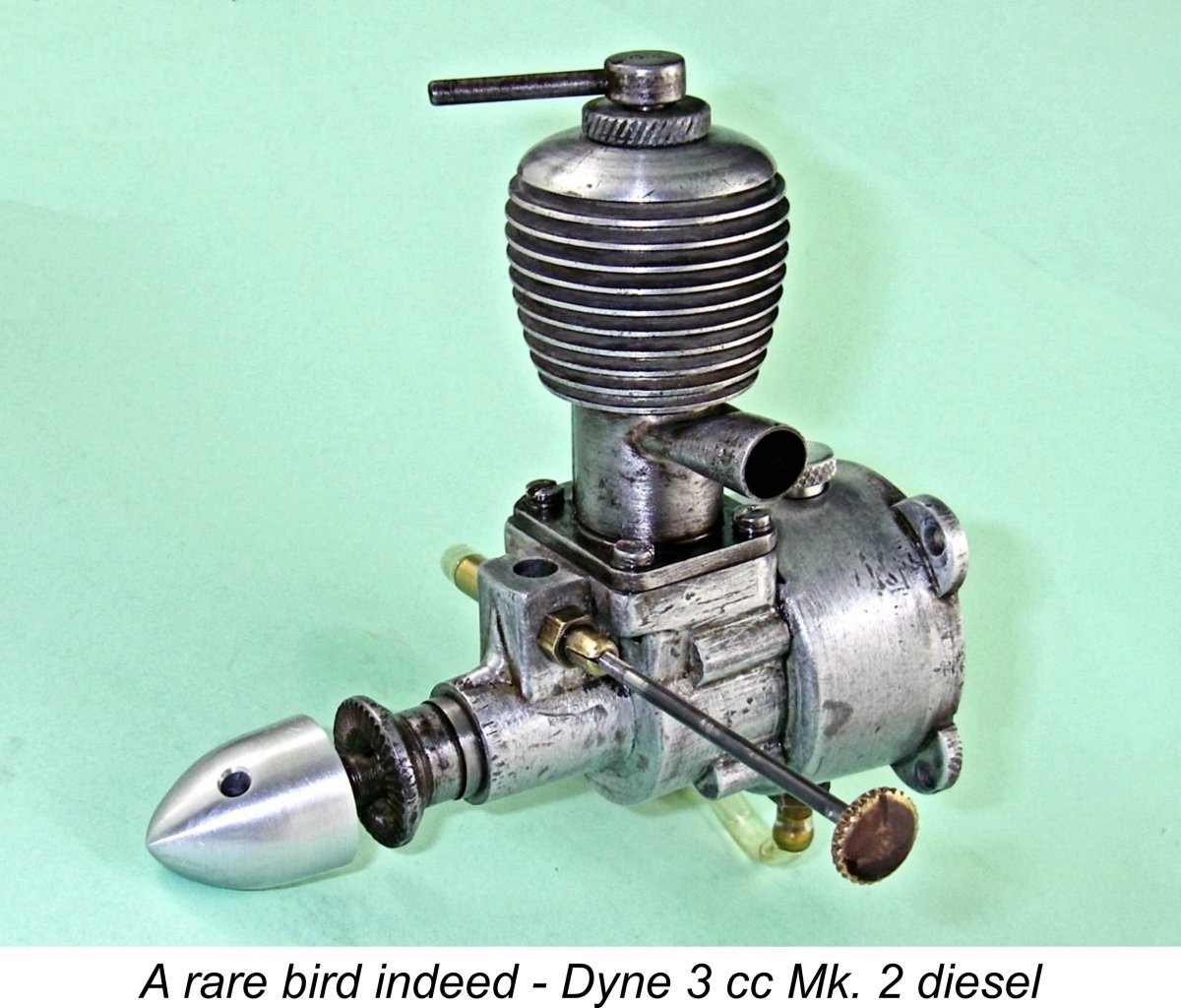 This is one of those articles which necessarily has to be based for the most part upon an examination of a few representative examples, images and advertisements relating to the marque in question rather than upon a detailed review of original documentary sources. This is because there’s a distinct lack of the latter material to consult! I’ll be sharing what I’ve been able to discover about the sparsely-documented and now very rare Dyne engines which were marketed from South Wales during the second half of the 1940’s.
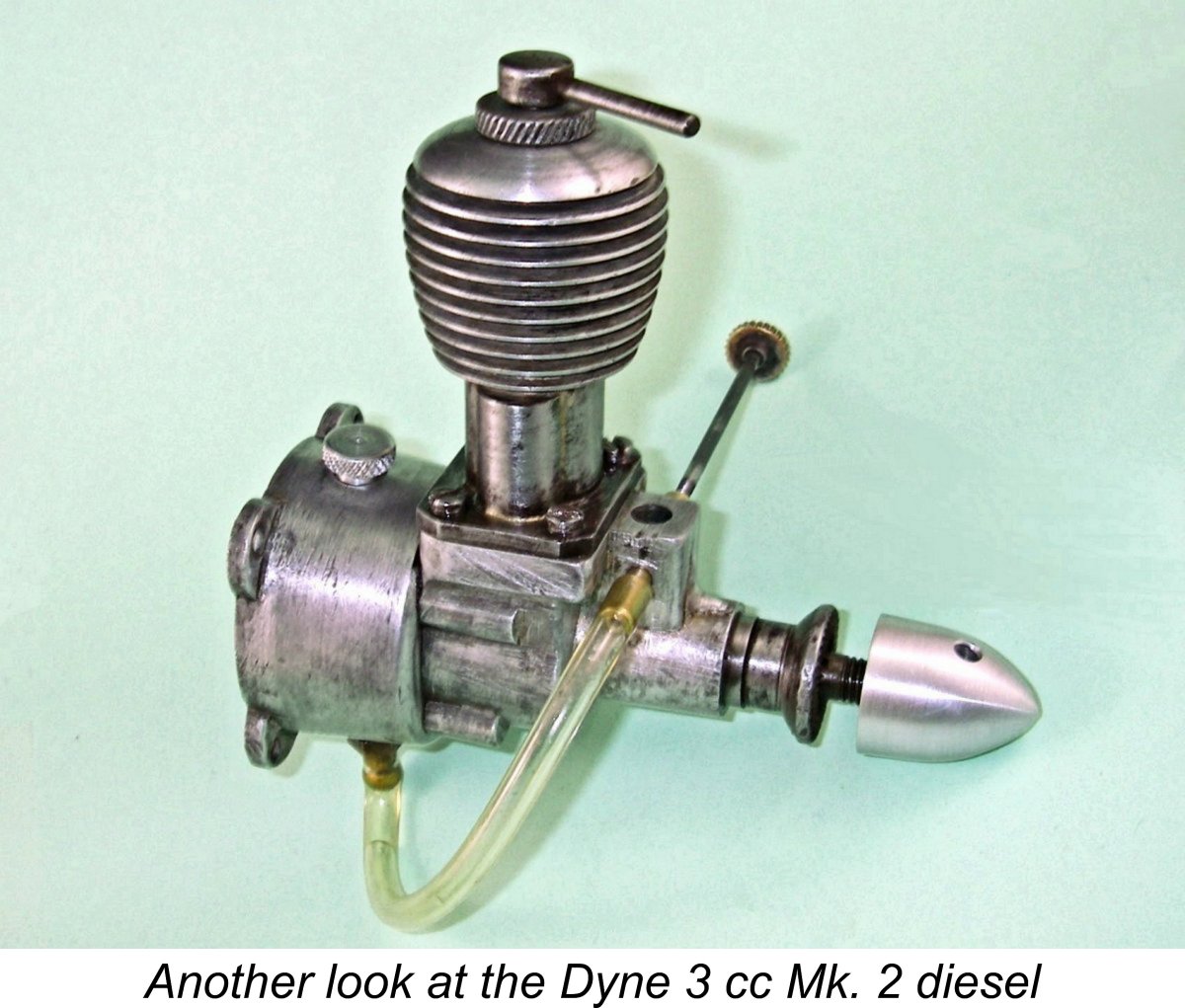
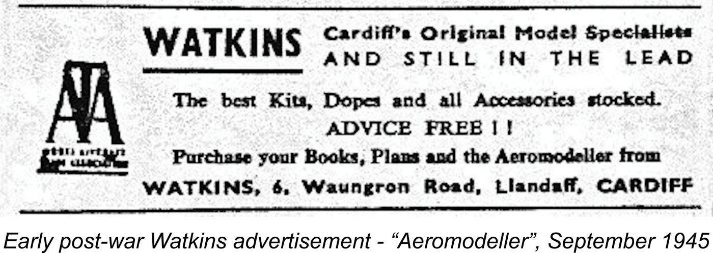
 That September 1945 advertisement informs us that the firm had already become a member of the Model Aircraft Trade Association (M.A.T.A.), whose logo appeared frequently in the firm's subsequent advertising. This was a predecessor organisation to the later Federation of Model Aeronautical Manufacturers and Wholesalers (F.M.A.M.W.) which was established in 1949 primarily to fight the infamous Purchase Tax case, of which more elsewhere in
 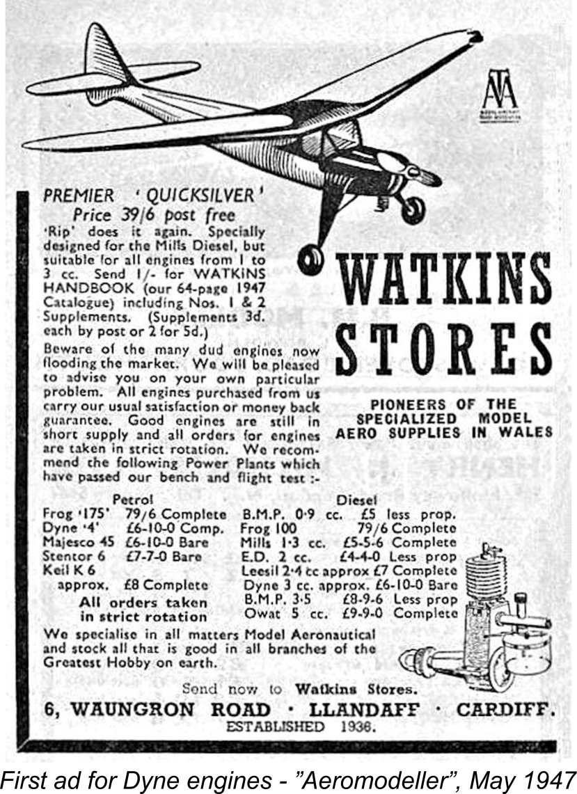 The Watkins company jumped onto the model engine bandwagon quite early on, quickly becoming enthusiastic and steadfast promoters of the Mills 1.3 diesel following its introduction in July 1946. They soon began adding other contemporary model engine ranges to their catalogue. They appear to have taken an unusually responsible approach to their participation in the model engine market, which at that time featured a number of offerings which had proved somewhat less than satisfactory in service. Their openly-stated policy was to test representative examples of all engines that they sold both on the bench and in the air prior to recommending them to their customers. Can’t say fairer than that!
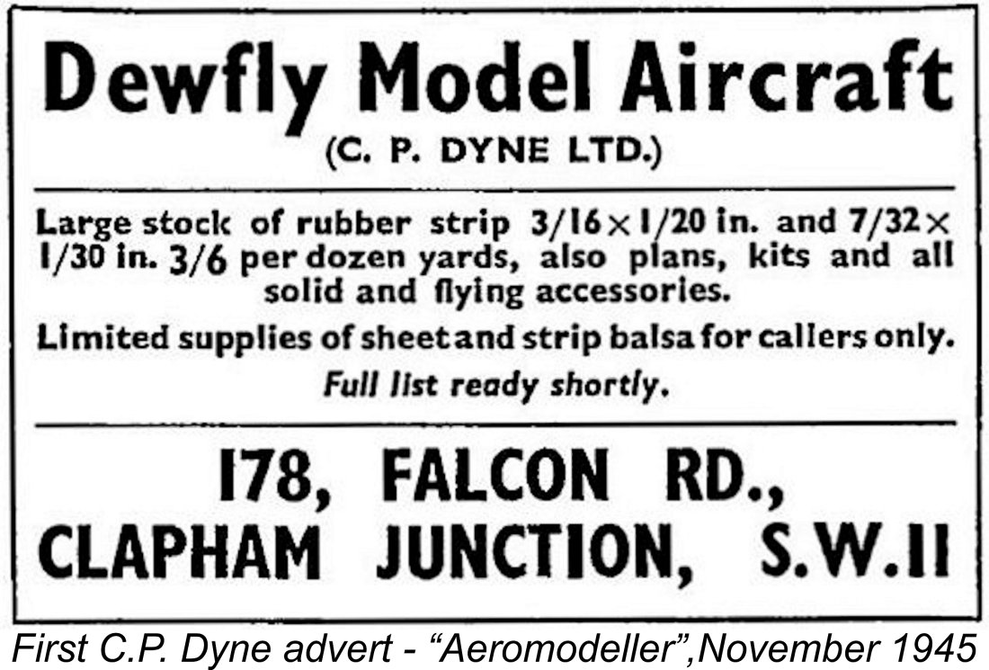
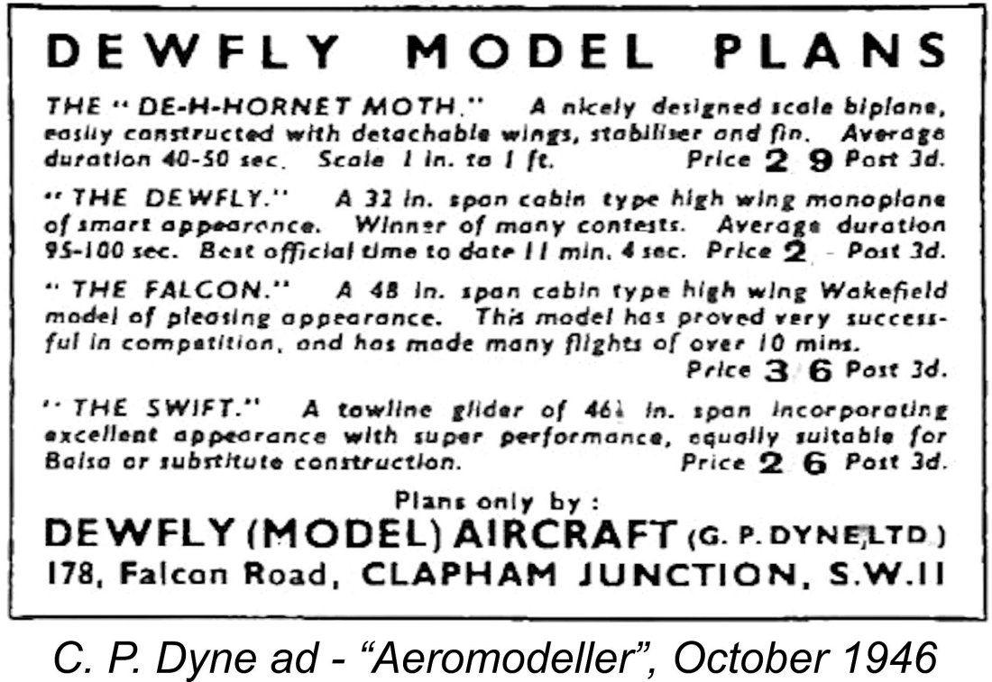 Now the key point to note is this. At no time did C. P. Dyne ever mention the Dyne engines, or indeed any other model engine range. In addition to the Dewfly plans, he certainly offered kits and accessories, including "all solid and flying accessories" as well as rubber strip and sheet or strip balsa wood. I find it to be completely beyond the bounds of credibility that if he had in fact manufactured a range of engines under his own name, Dyne would not have advertised and sold them on his own account in the major market area of Greater London where he had been well established for years. WHY would he choose instead to market them exclusively through a relatively obscure model shop located hundreds of miles away in South Wales?
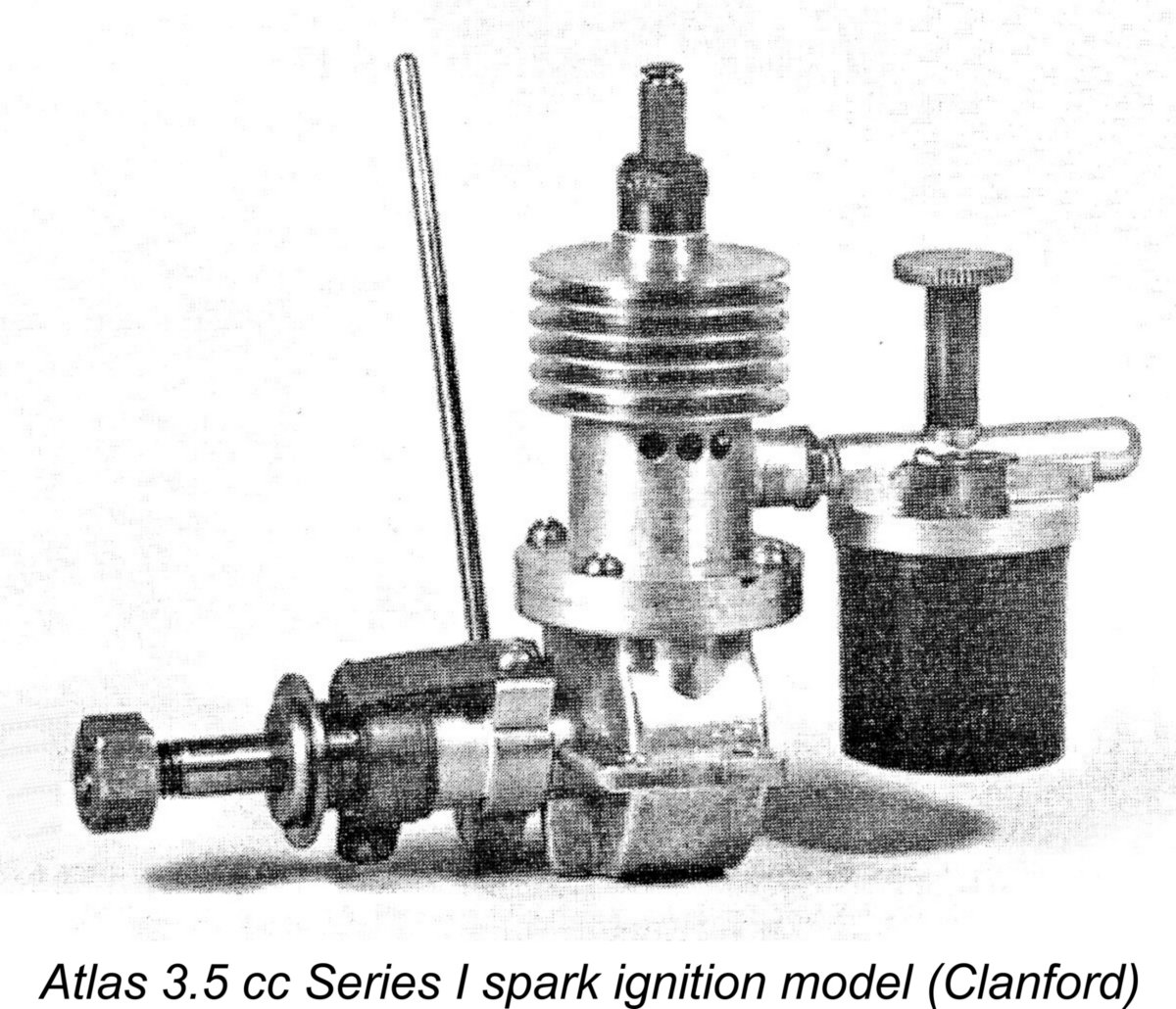
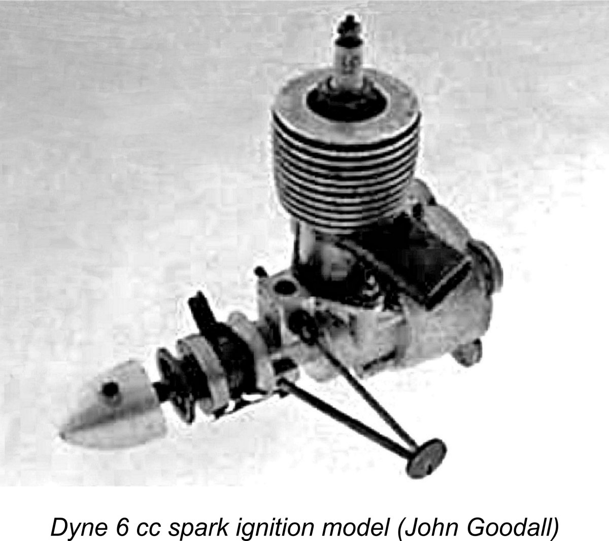 The next question is that of chronology. Although once again we have absolutely no firm evidence for this, it seems to me to be highly likely that the range actually had its origins some time prior to the date of its May 1947 adoption by Watkins. Both the style of the Dyne spark ignition engines and the fact that most of them were never mentioned in any of Watkins’ subsequent advertising combine to suggest that the majority (if not all) of them were introduced by their manufacturer during the pre-Watkins era, most likely in 1946. This could well have included the spark ignition models in 2 cc, 3 cc, 4 cc, 6 cc and 10 cc displacements which are known to exist (see below).
 At the time in question, a considerable pent-up demand for model engines existed in Britain, both as a result of a natural post-war desire to resume peace-time hobbies and on account of the novelty appeal of model engines during those early post-war years. Although the cost of such engines was significant in the context of the cash-starved British post-war economy, their novelty value encouraged people to save up and buy them anyway. Engines were in relatively short supply at the time, so any motor that would start and run reasonably well most of the time was pretty much assured of a buyer.
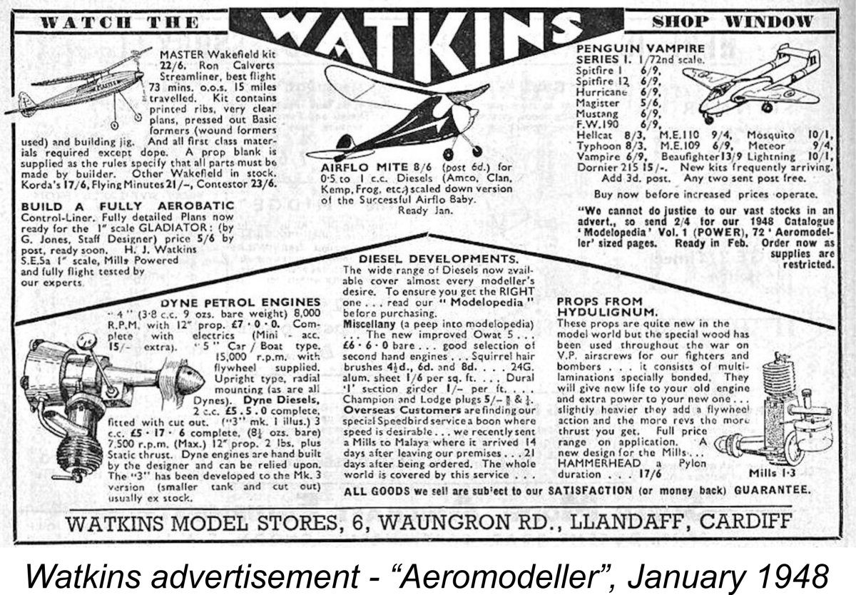 t seems to me to be very likely that the Dyne range had a similar low-key genesis during this era, although there’s presently no direct evidence for this. That said, some support for this view is found in a statement in Watkins’ January 1948 advertisement to the effect that “Dyne engines are hand-built by the designer” - note the singular form of the last word, which suggests a single individual. This certainly smacks of the proverbial one-man garden shed operation, and indeed the very small number of present-day survivors from among the many and varied models that were produced before and during the range’s two-year promotional period implies a very low production rate consistent with an individual artisan origin.
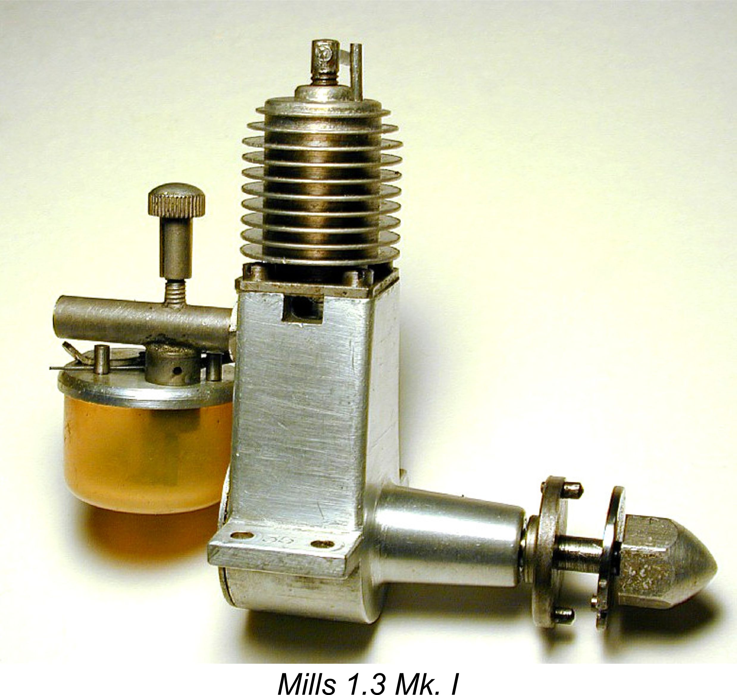 Despite their adoption of the Dyne marque as an exclusive Watkins “house range”, the company did not promote the Dyne engines to the exclusion of all others. On the contrary, they continued to vigorously promote the Mills engines, omitting any reference to the Dyne range in a number of their later advertisements while continuing to extoll the virtues of the Mills to the skies. The fact that they evidently placed the Dyne engines at the same level of quality as the Mills again reflects well upon their view of the Dyne range.
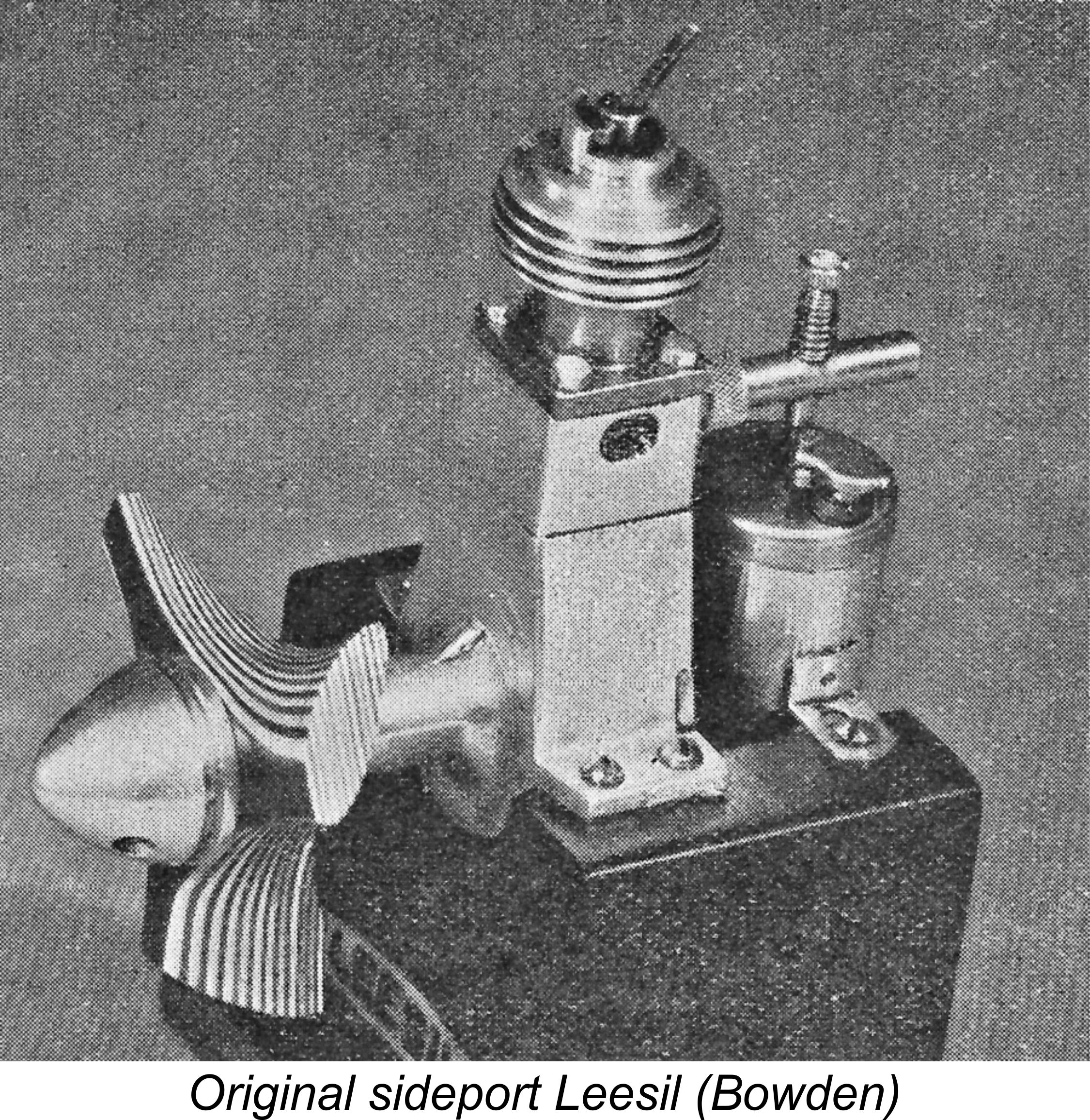 Watkins' most interesting listing in May 1947 was for the
  There were also the
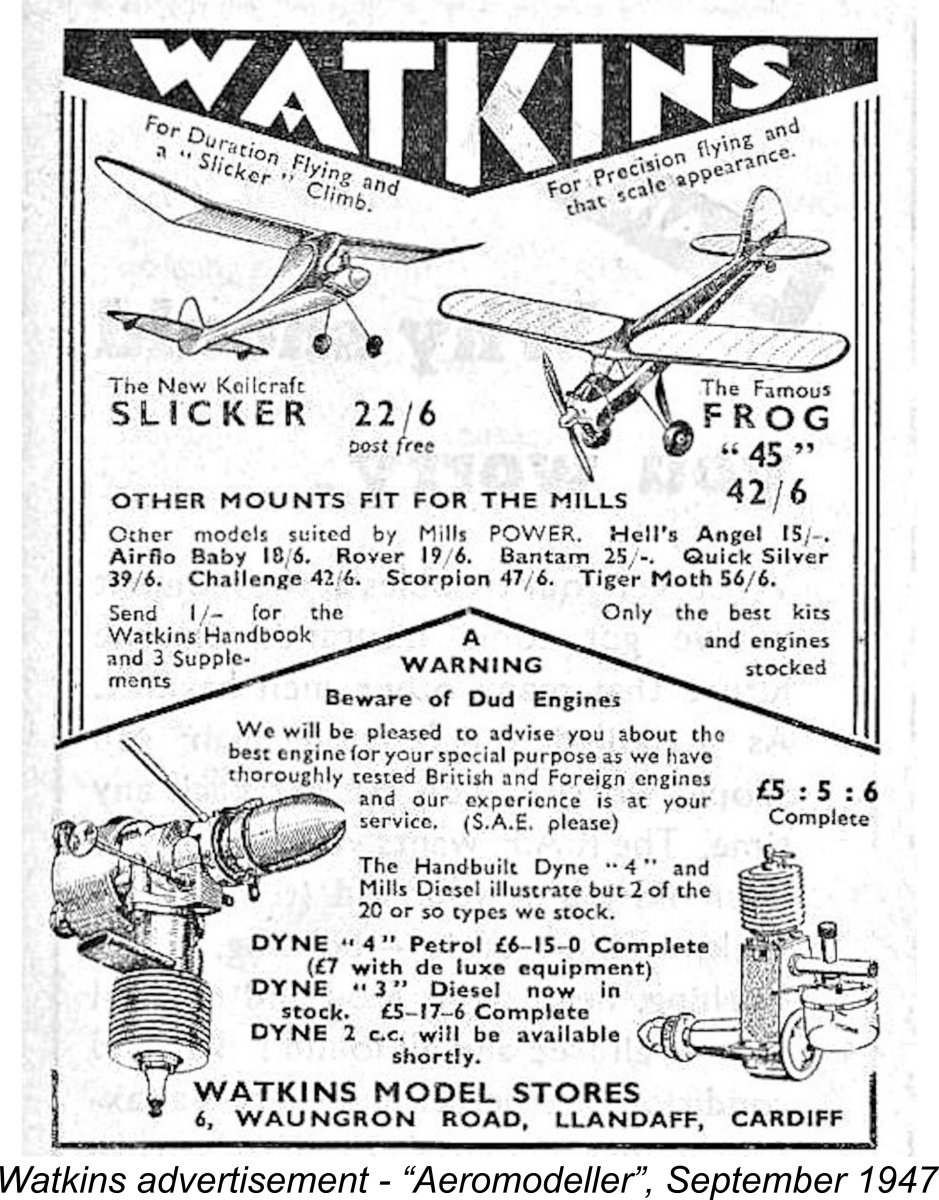
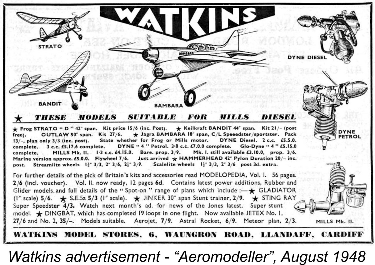 r tank with cut-out. It would appear that the Mk. 2 version must have been relatively short-lived! However, it did exist – an illustration of the Dyne 3 which appeared in one of the Watkins advertisements (see below) was specifically identified as a Mk. 2 version. Moreover, one of my own examples appears to be a Mk. 2 model, of which much more in its place.
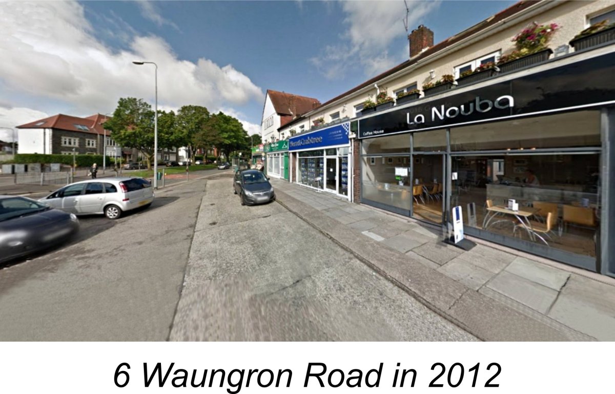
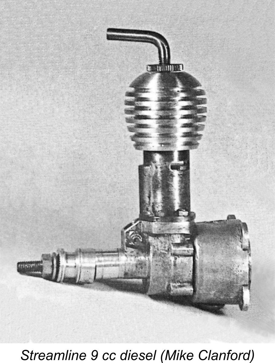 om the late prominent collector Jack Law, who provided a little information on the Streamline engines. Jack had been in contact with Vince Redfern, who had consulted his notes from previous years. Vince's notes apparently confirmed that the Streamline engines were made or at least assembled by one Marcus Maurice (d. 1980) of Wigston, Leicester. Another chap named Lattaway was also involved.
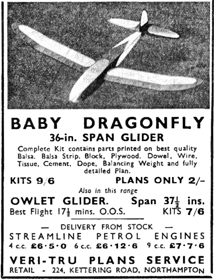
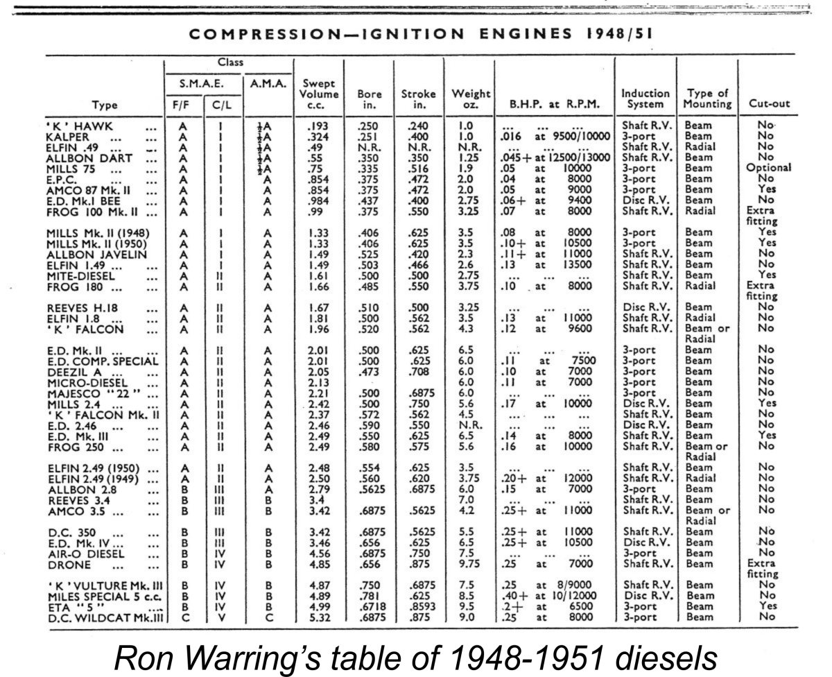 Apart from an October 1948
 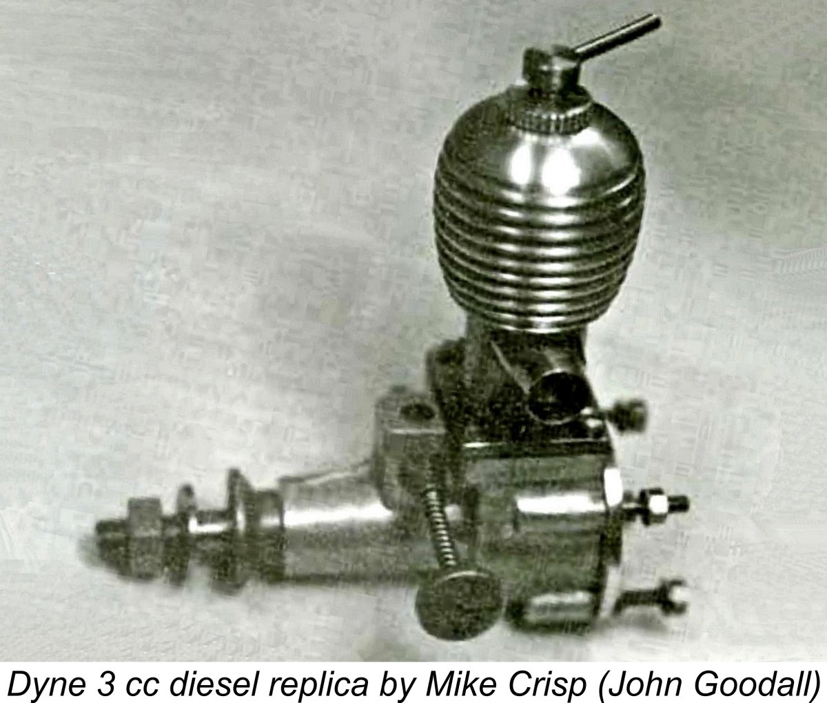 The Dyne range made another appearance in MEW in the November 1998 issue. This took the form of a very short article by the respected model engine builder and restorer Mike Crisp, who constructed a replica Dyne 3 cc diesel using an original crankcase provided by John Goodall. The other components were replicated from an original engine also provided by John. The result was a superb-looking replica which started and ran very well, with what Mike Crisp described as "a lovely "crackle" from the exhaust pipe". However, once again no information was provided about the origins of the Dyne range.
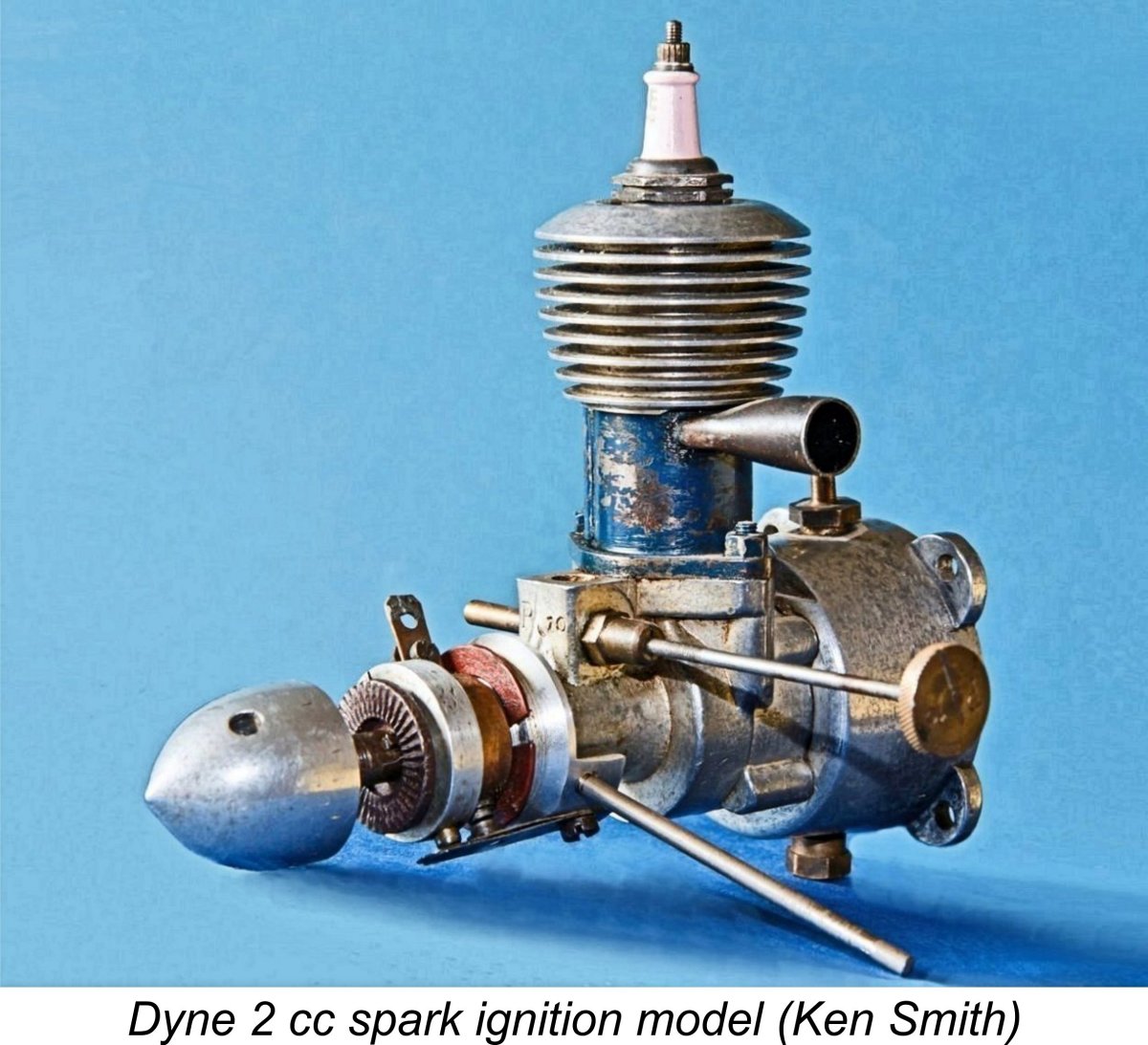
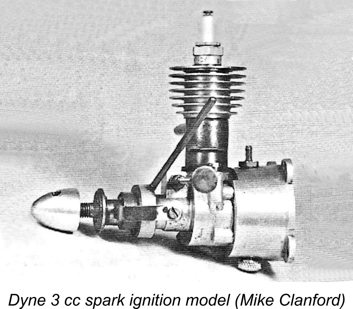 This engine is another one (like the previously described 2 cc sparker) that nearly got away! It is documented solely through the inclusion of an image in Mike Clanford’s previously-cited A-Z book. That image is reproduced here with full acknowledgement.
 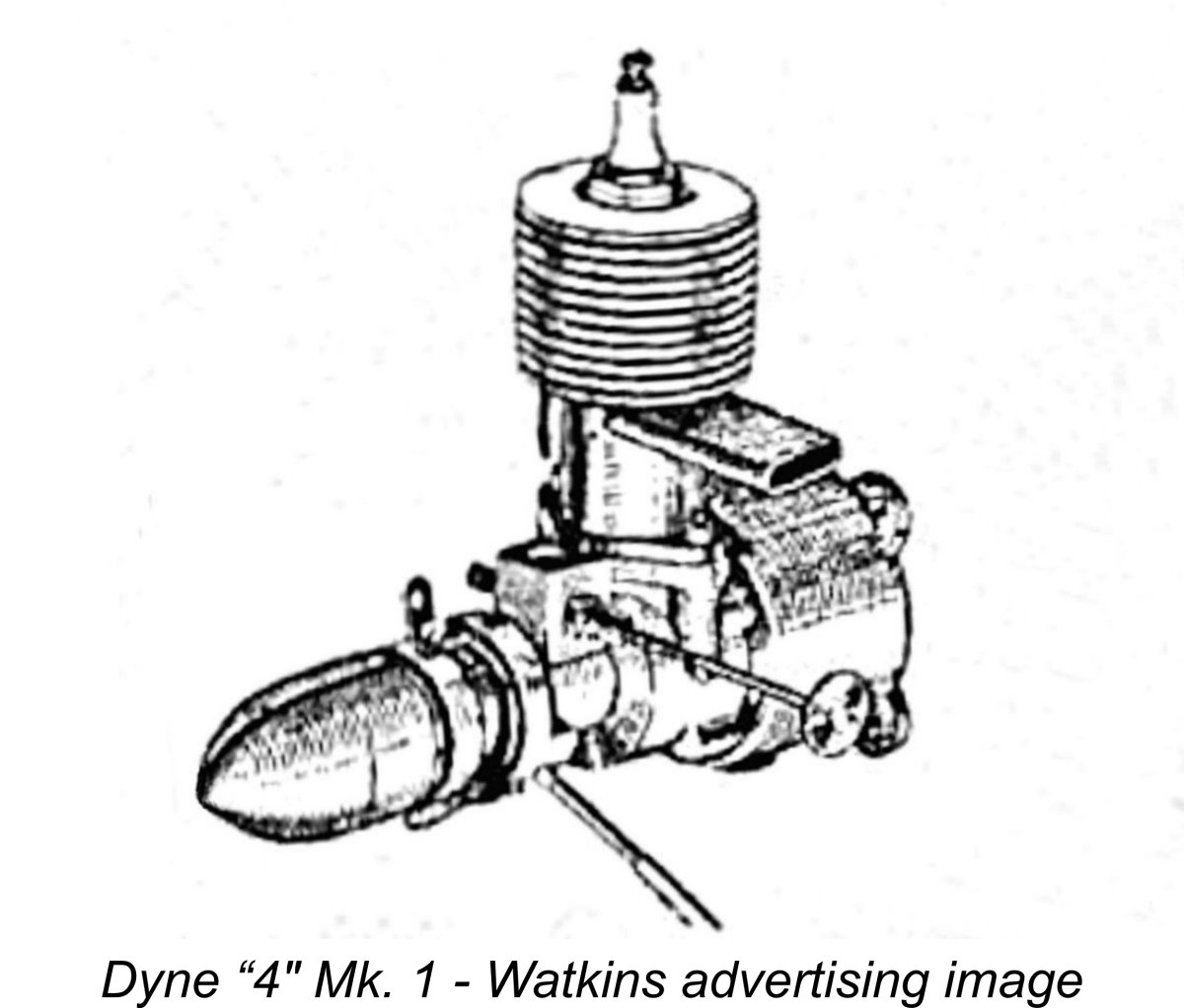 The Dyne 4 was among the British-made spark ignition models featured in Appendix II (Design and Construction Data) of Ron Warring’s previously-cited 1949 book. Unfortunately, it appears that Warring did not have direct access to an example of the engine, since he was unable to supply much in the way of detail. Furthermore, some of the details that he did supply are at odds with the claims made by Watkins in their advertising. For example, Warring gave the displacement as 4 cc (0.244 cuin.), whereas at least two Watkins advertisements cited the true displacement as 3.8 cc (0.232 cuin.). Since Warring provided no bore and stroke measurements, the basis for his displacement claim is unclear. Presumably he was quoting a nominal figure.
 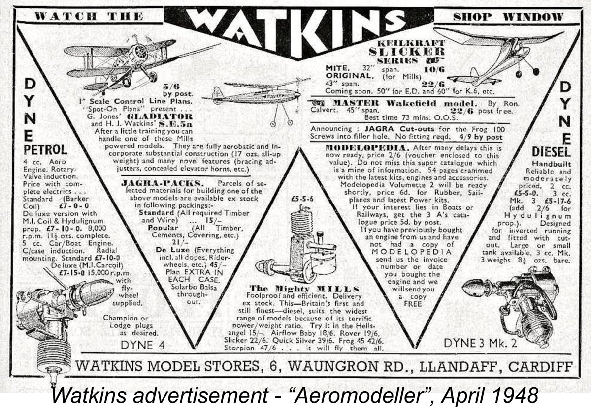 This may sound like quite a lot of money for a spark ignition engine of this displacement and type, and that's certainly true in the context of the cash-starved early post-war British economy. However, it was in fact quite competitive by comparison with other makes at the time. For example, the excellent Majesco “45” sold for a more or less identical price of £6 10s 0d (£6.50), while the Stentor 6 was priced at £7 7s 0d (£7.35). This was during a period in which a man earning £8 a week before taxes was considered to be well off! Model engines weren’t cheap…………
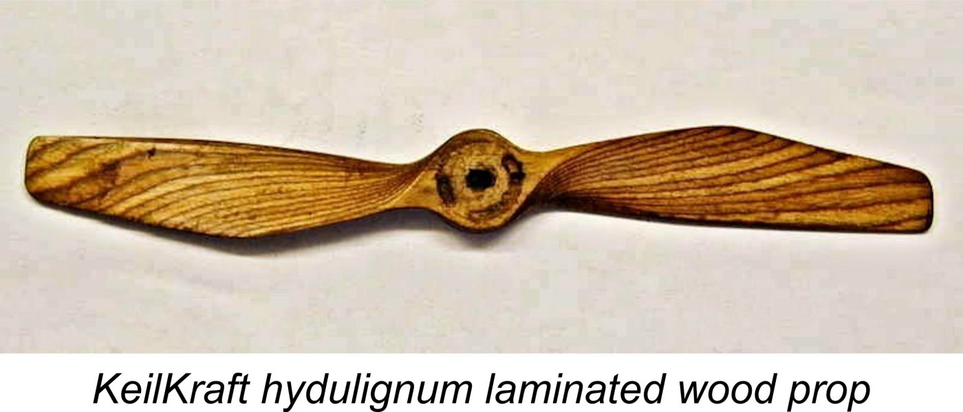 The Watkins company actually made much of their hydulignum airscrews. Their January 1948 advertisement had included the statement that “These props are quite new in the model world, but the special wood has been used throughout the war on V.P. airscrews for our fighters and bombers…………it consists of multi-laminations specially bonded. They will give new life to your old engine and extra power to your new one ………. slightly heavier, however they add a flywheel action and the more revs, the more thrust you get”. Somewhat fuzzy logic there .........still, a number of contemporary firms, including KeilKraft, offered props made using this material.
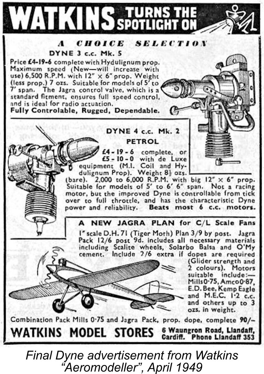 0d (£5.50). This final offering may imply that production had already ceased by this time and the company was attempting to sell off remaining stocks. Indeed, as mentioned earlier, Watkins seemingly closed its doors a few months later. It’s likely that the writing was already on the wall as of April 1949.
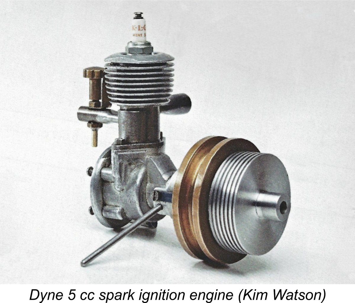 It appeared that this description must have referred to the use of sideport induction in this model. John Goodall's previously-quoted article in the May 1996 issue of MEW included a comment from Watkins' "Modelopedia" catalogue on the Dyne 5. The relevant entry read as follows:
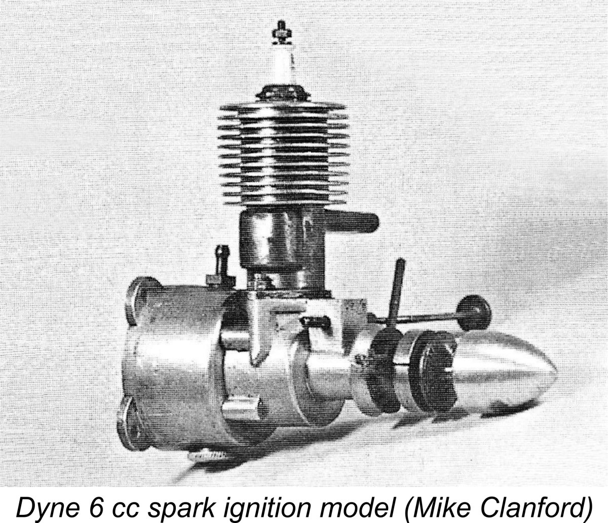 This is another model which never appeared at any time in Watkins’ advertising, nor was it included in Ron Warring’s previously-cited book. The latter observation appears to confirm that it had been out of production for quite a while when Warring was compiling his data in the latter part of 1948.
 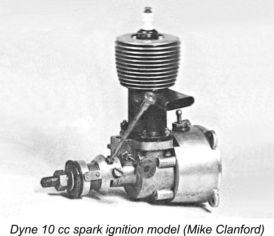 The same comments as those applied above to the Dyne 6 cc model apply equally to the 10 cc product of the same workshop. It too was never mentioned by Watkins, nor did Ron Warring take note of it. Consequently, we have no technical data whatsoever – only the attached image extracted from Mike Clanford’s A-Z compilation. It seems highly likely that this model too dated from the period prior to Watkins becoming involved in the marketing of the Dyne range.
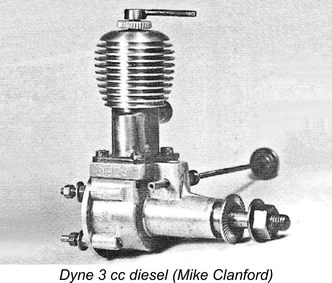 The Dyne 3 followed the manufacturer’s standard design pattern in all respects. It was an FRV unit having a radial tank mount – no provision was made for beam mounting. In the case of this model, we have bore and stroke dimensions to confirm the engine’s displacement. Ron Warring gave the bore and stroke as both nominally 0.625 in. (15.875 mm) for an actual displacement of 3.14 cc (0.192 cuin.). These figures check out in both of my examples.
 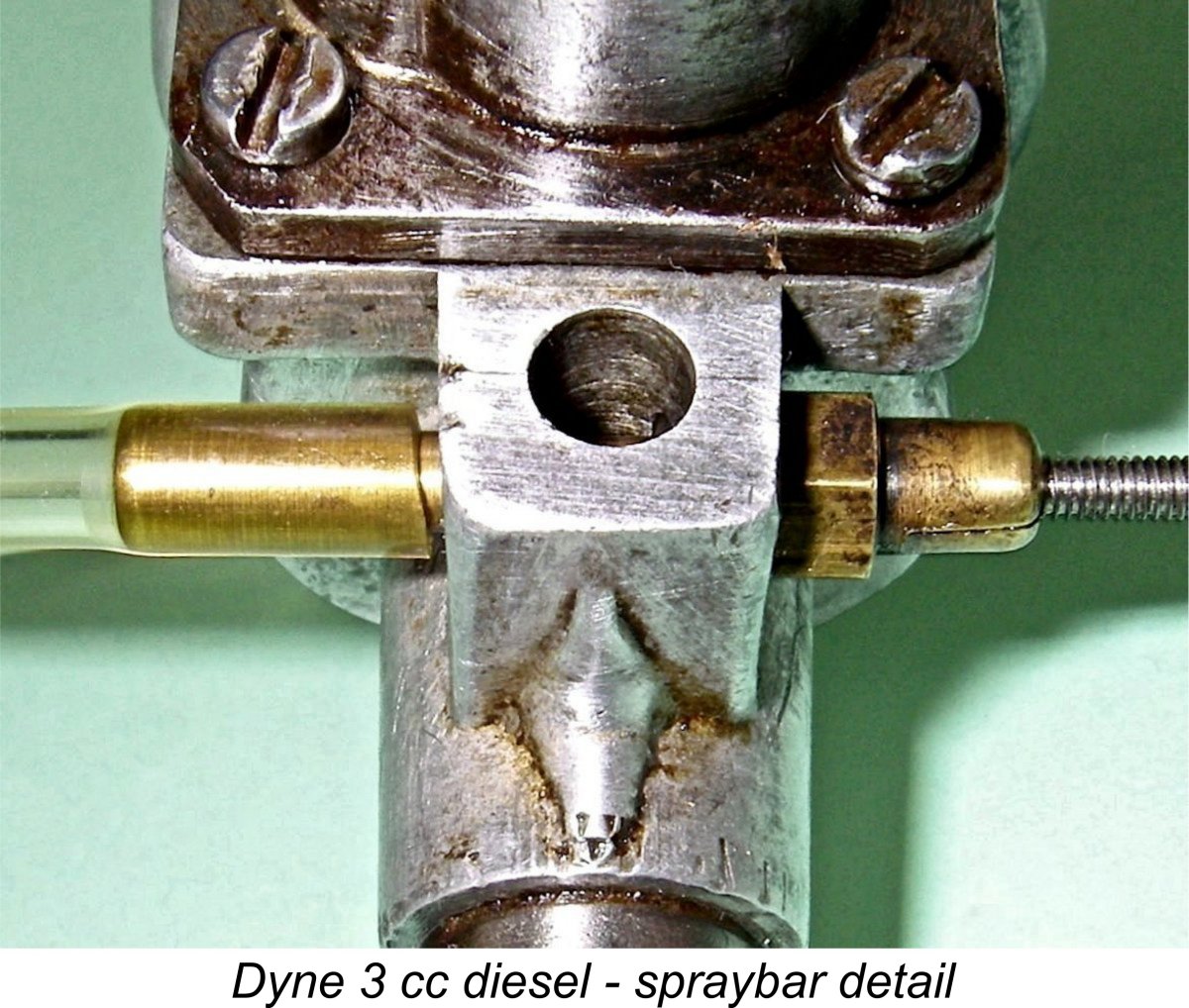 The needle valve is of somewhat unusual form, consisting of only two components - an unusually long externally-threaded needle and a brass spraybar. The hole for the spraybar is drilled transversely through the intake venturi at spraybar diameter in the usual way, but is then tapped on the needle side only. The internally-threaded sprayar itself features a short length of expanded diameter on the needle side which is externally threaded to fit the tapping of the needle-side spraybar hole. The spraybar then simply screws into its mounting hole, no nut being required to retain it. Since two opposing jet holes are provided, its final radial position when tightened does not much matter. Needle tension is provided by a split of the outer end of the spraybar on the needle side.
 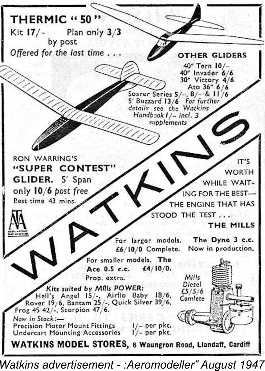 was trolling for advance orders, as they seem to have been doing with their Leesil offering.
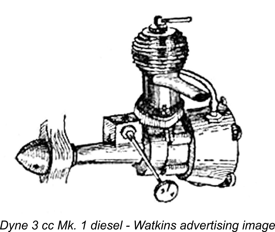 The attached advertising image show the engine in what was specifically cited in one of Watkins’ advertisements as its Mk. 1 form. Unfortunately this is the sole confirmed image of a Mk. 1 variant that I’ve so far been able to find – apologies for the poor quality, but any image is surely better than none! The level of detail is sufficient to show that this variant had a rather small round-profiled cooling jacket and a tank of conoidal form. The tank was equipped with four seemingly-vulnerable “mouse ear” lugs for radial mounting.
  ges may be quickly and easily implemented at any time. It would appear that the weak points noted above soon presented themselves to the manufacturer, because the Mk. 1 variant was replaced quite early on with a Mk. 2 model which addressed a number of these concerns. The engine illustrated at the right was specifically identified in Watkins advertising as a Mk. 2 model.
 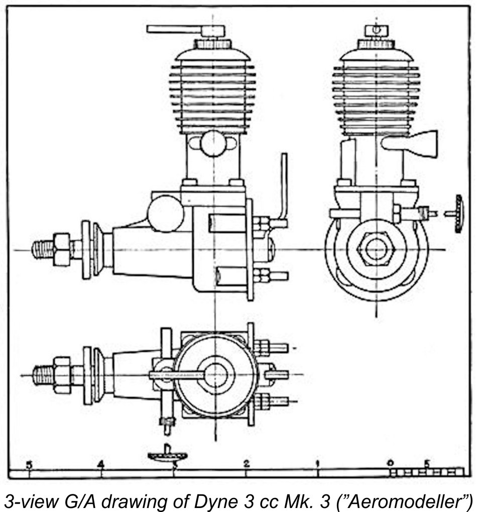 The Dyne 3 was still being offered in December 1947 at an unchanged price, but now it was specifically stated to be fitted with a Jagra fuel cut-out. This is not to be confused with the Jagra control valve mentioned earlier – rather, it was a simple fuel cut-out device intended solely to stop the engine rather than to control its speed. The advent of diesels had made such devices necessary since engine runs in free flight models could no longer be terminated by switching off the ignition.
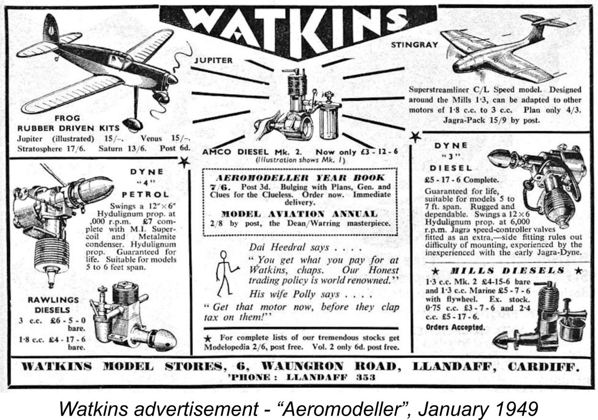 ntinued to be advertised throughout 1948 at the same selling price of £5 17s 6d (£5.87). However, as of January 1949 the advertisements claimed that the Jagra control valve was now an optional extra as opposed to a standard fitting. Furthermore, the valve (when fitted) had been relocated from the engine’s backplate to the side of the crankcase. This was reportedly done to alleviate mounting difficulties which had resulted from the valve’s former backplate location, which understandably interfered with the engine’s radial mounting.
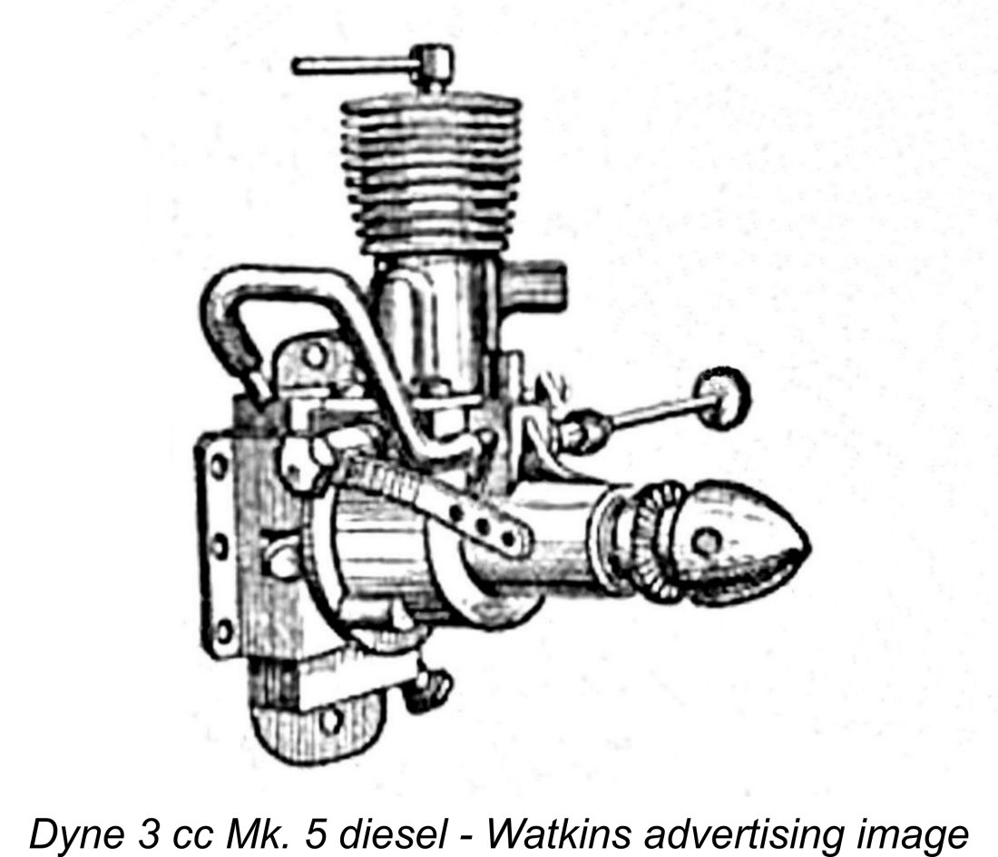
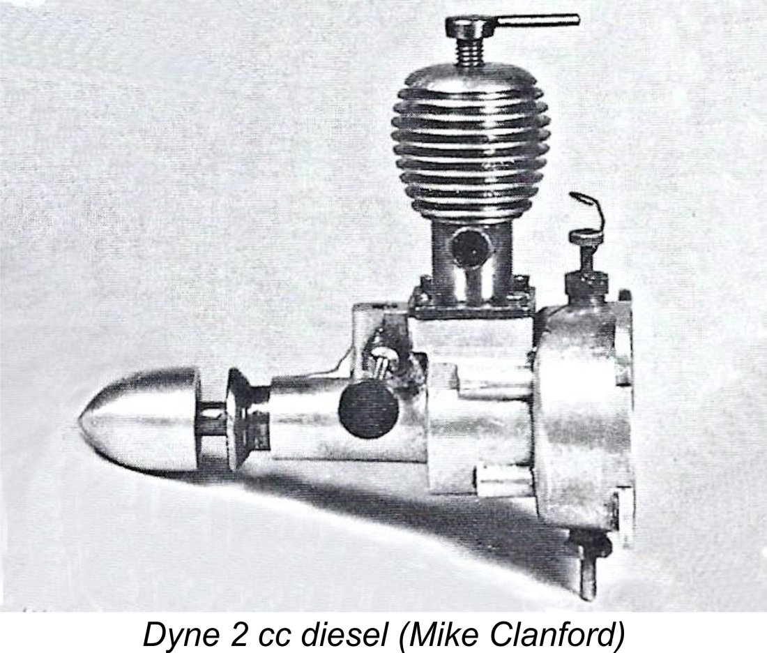 e 2 cc diesel was in effect a Mk. 2 Dyne 3 model with a reduced bore – the stroke remained unchanged. It seems to have been a diesel derivative of the 2 cc spark ignition model described earlier, since Ron Warring reported identical nominal bore and stroke measurements of 0.500 in. (12.7 mm) and 0.625 in. (15.87 mm) respectively for an actual displacement of 2.01 cc (0.123 cuin.). The weight given by Warring was 6.75 ounces (191 gm), which can’t be checked in the absence of an example because Watkins never gave a weight figure for this model. Once again, this is rather a lot of weight for a 2 cc diesel, especially when one considers that the competing 2 cc
 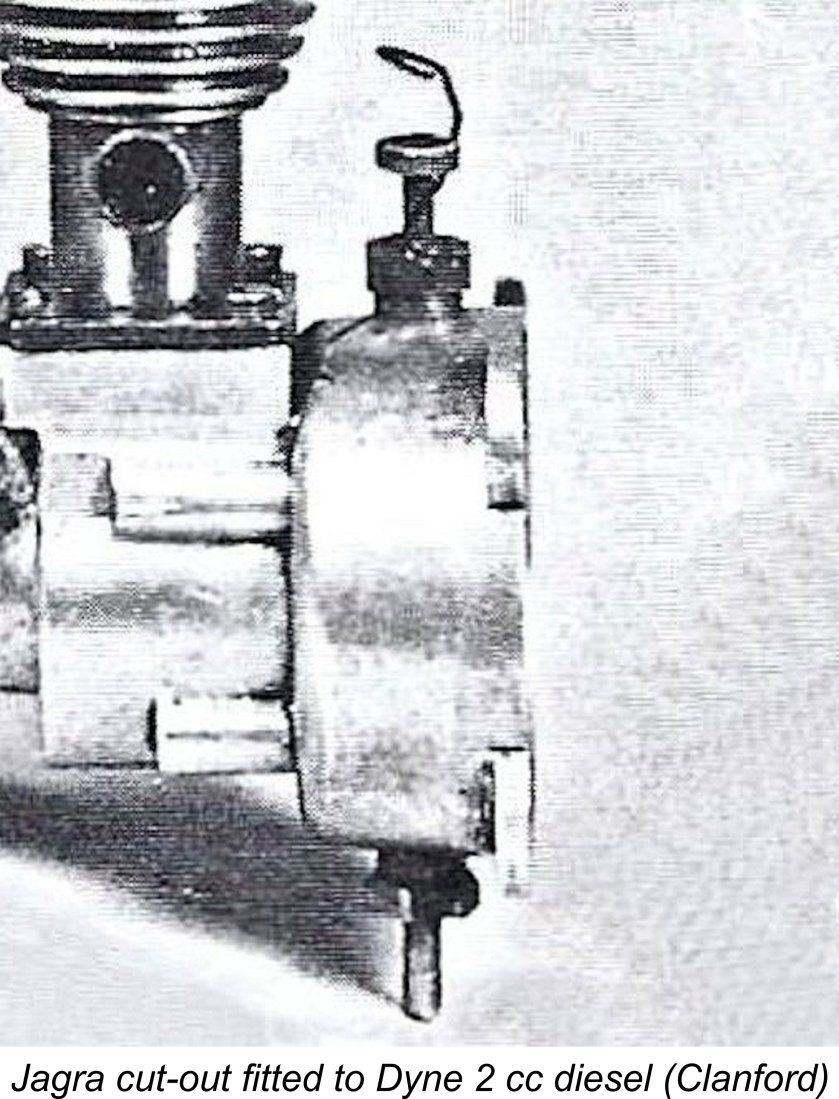 flight and 8x6 for control line.
 I’ve left this one to the last because quite frankly I have no idea where it sits in the Dyne hierarchy! In large part, this is due to the fact that it was never advertised at any time.
 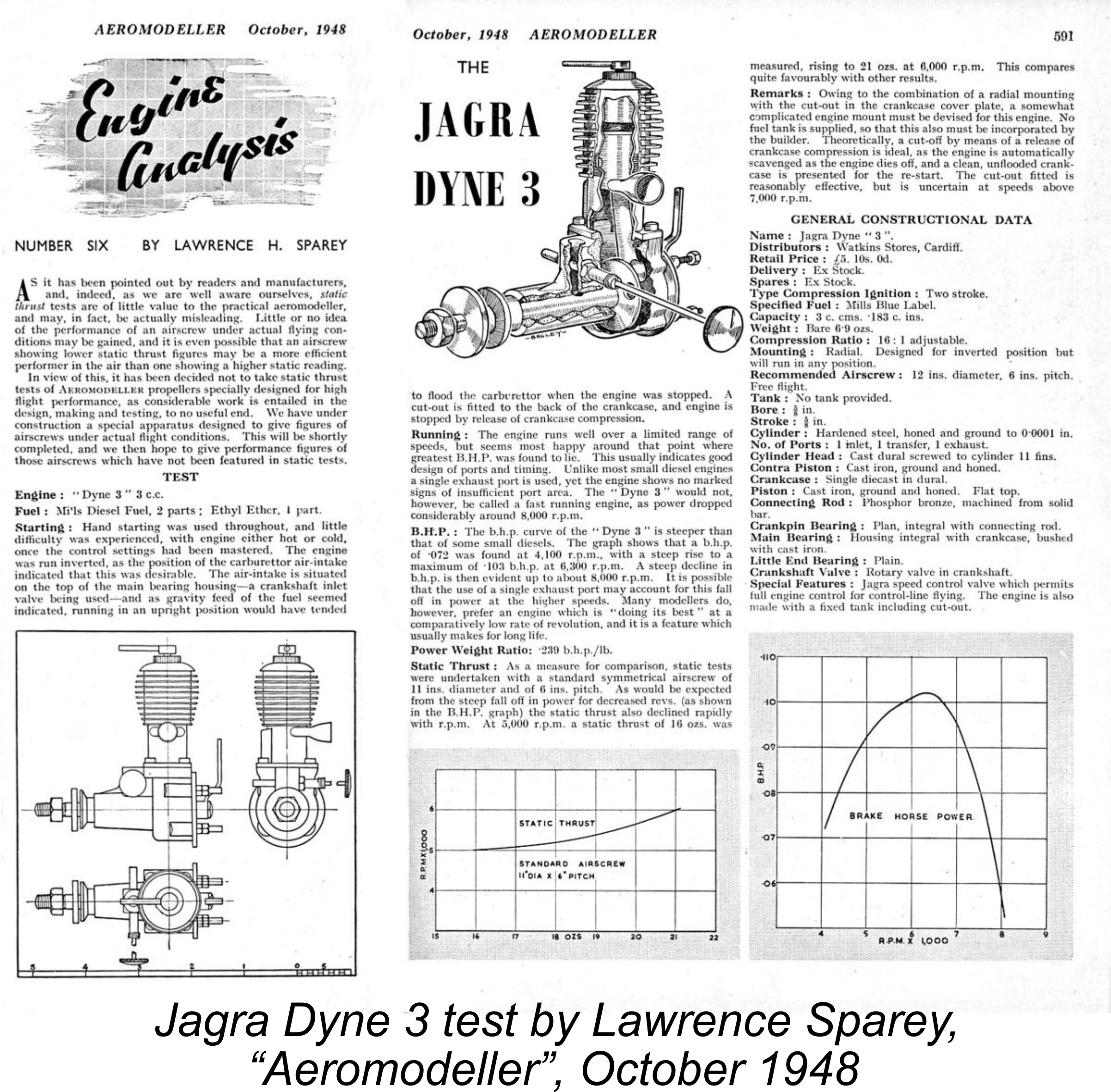 As mentioned earlier, the Dyne 3 diesel was the sole representative of the range to become the subject of a published test in the contemporary modelling media. Lawrence H. Sparey’s
 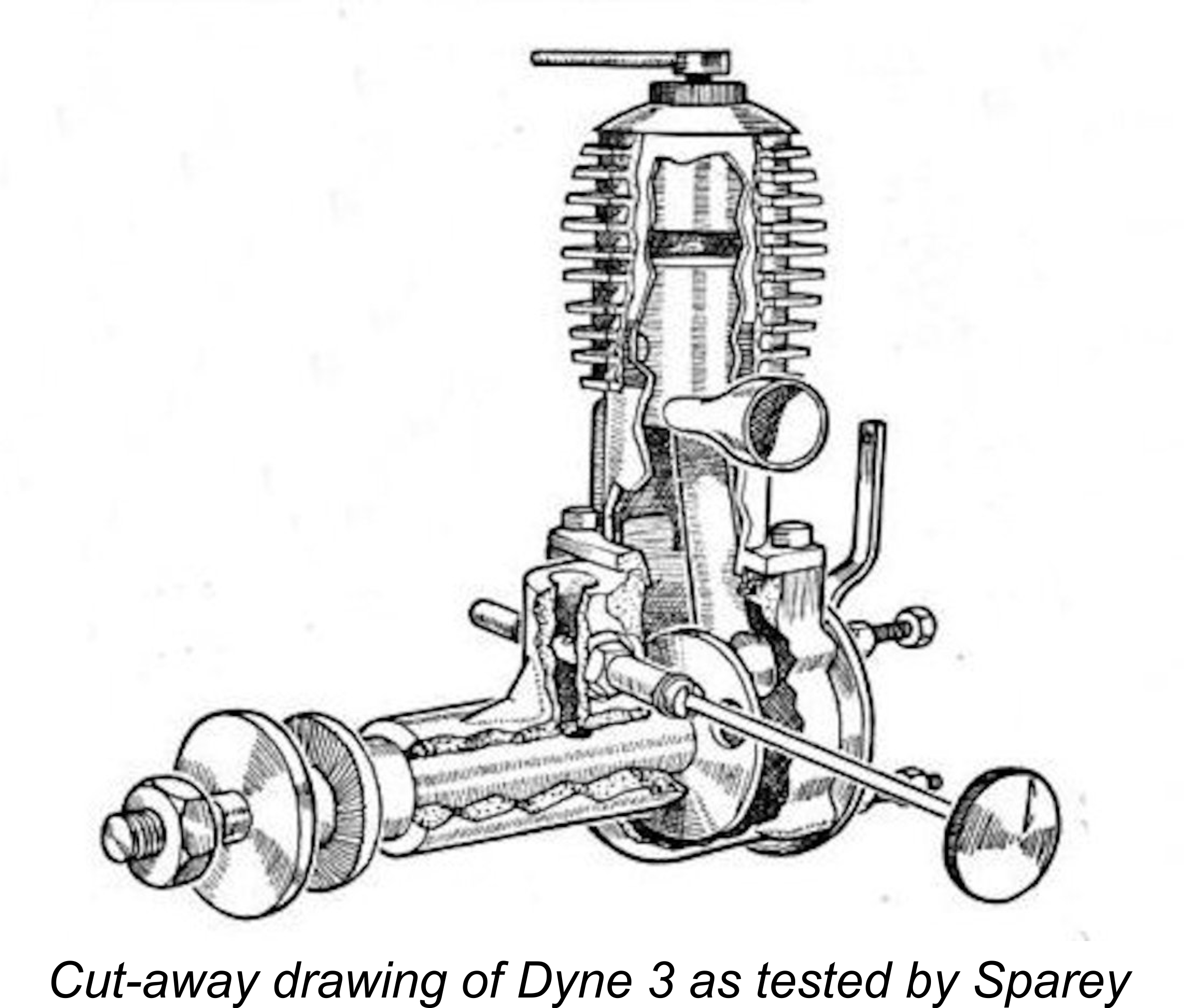 One perfectly valid comment made by Sparey in connection with the Jagra control valve and the engine’s radial mounting was that “a somewhat complicated engine mount must be devised for this engine”. Looks like an example of typical English understatement to me! It seems that the makers must have heeded this comment, because the attentive reader will recall that their January 1949 advertisement claimed that the Jagra control valve was now an optional extra as opposed to a standard fitting. Furthermore, the valve (when fitted) had been relocated from the engine’s backplate to the side of the crankcase. This was reportedly done to alleviate mounting difficulties which had resulted from the valve’s former backplate location. Vindication for Lawrence Sparey!
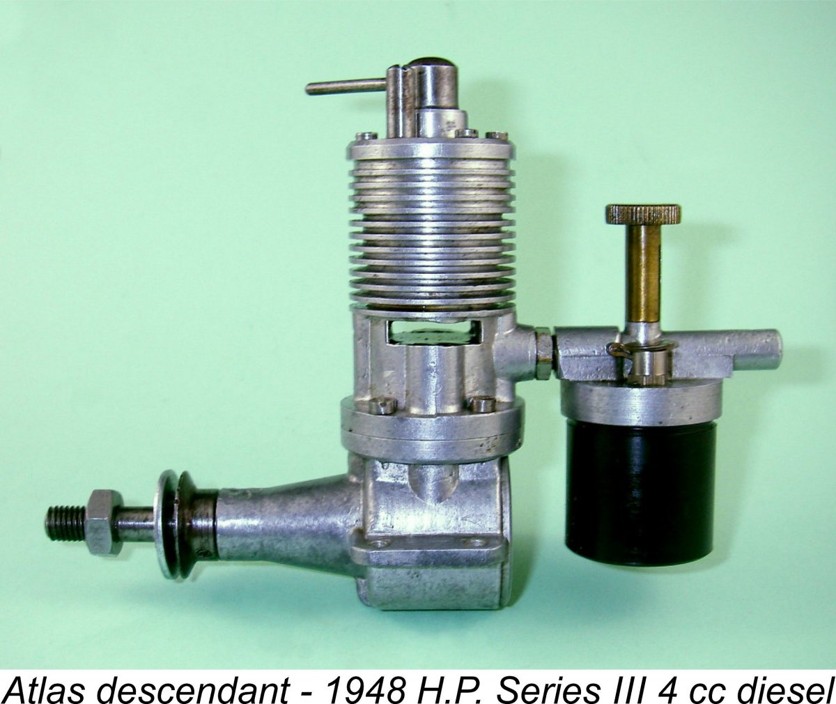 Frustratingly, Sparey was silent on the matter of the engine's manufacturer, limiting himself to identifying Watkins Stores of Cardiff as the distributors of the engine. This pretty much confirms that Atlas Motors had nothing to do with the Dyne engines. Indeed, by this time they had actually transferred their model engine manufacturing activities to a totally different company, Henleyston Products of Barnet in Hertfordshire, who had re-developed the Atlas models into the
  Although it featured excellent running fits, the example of the Dyne 3 so kindly supplied by Kevin Richards was by no means in pristine condition. It had clearly had a fair bit of previous use, and this showed! The most significant problem was the fact that the original one-piece crankshaft had presumably suffered a failure in use and had been repaired rather imprecisely by brazing.
 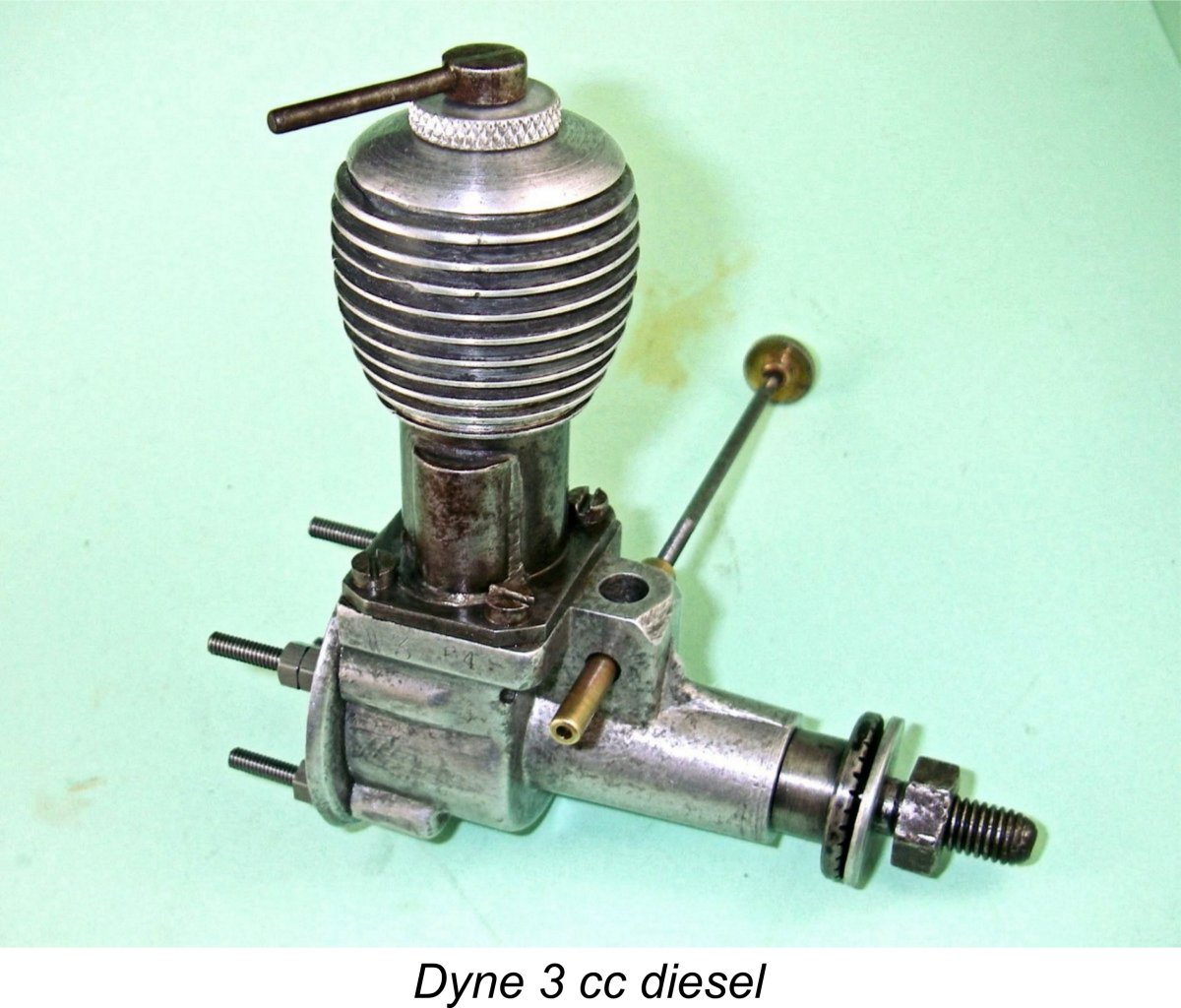 it was, I contented myself with making a new compression locking ring. This put the engine into completely original external configuration apart from the missing stack, the absence of which should not affect performance in any way. In this state, the engine weighed in at 6.60 ounces (187 gm), admittedly without a tank and minus its stack. Since Lawrence Sparey reported the weight of the tankless Jagra Dyne with the control valve fitted as 6.9 ounces, it would appear that the control valve added some 0.2 ounces of extra weight, allowing for the weight of the missing stack on my example.
 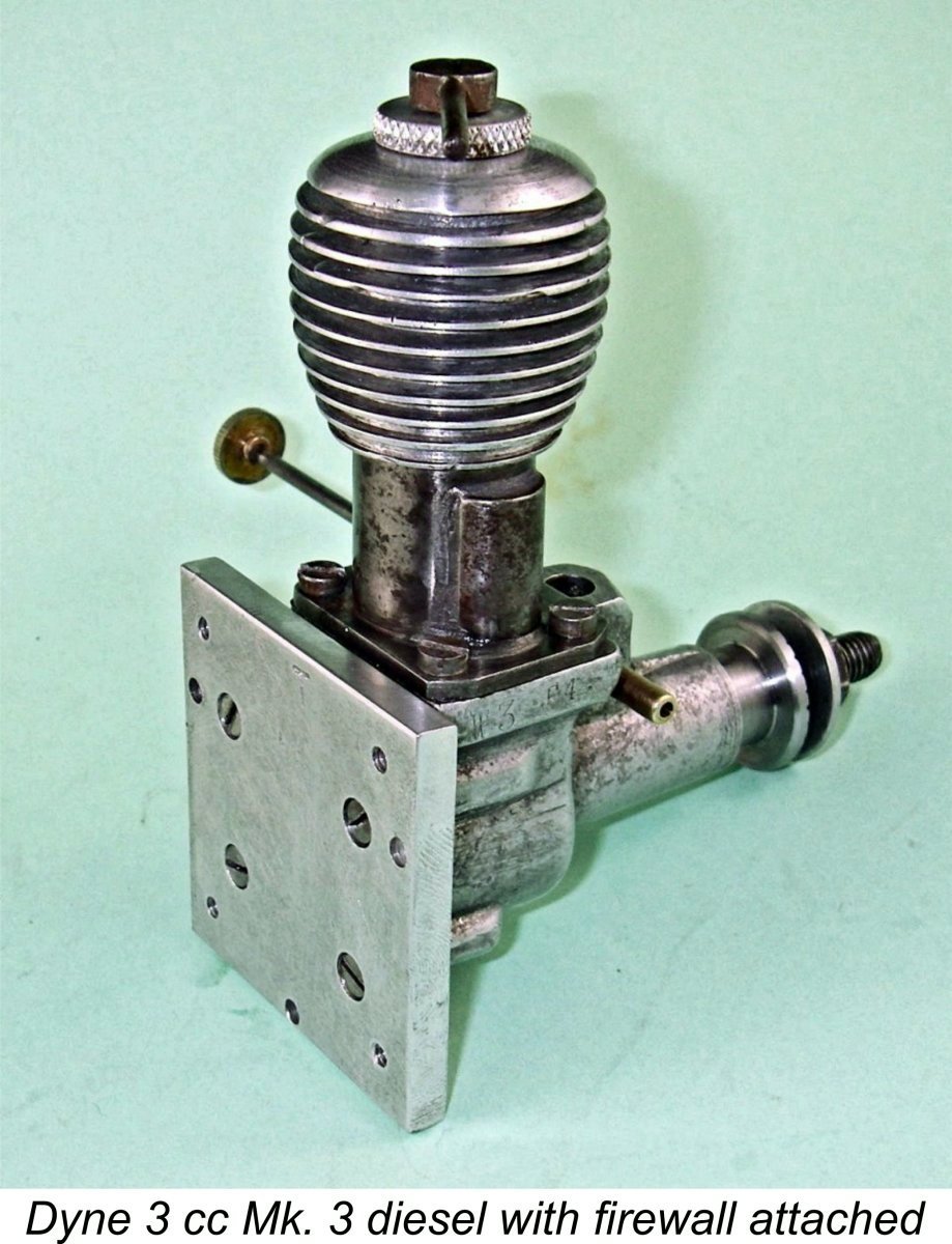 The presence at the rear of the crankcase of those four long 6 BA studs with a pair of nuts each for radial mounting of this variant presents a highly inconvenient installation challenge, it must be said. To mount the engine, you'd have to provide a firewall with holes located to allow the free passage of those studs, which would then have to be secured by nuts installed from behind the firewall. In many models, access to the rear of the firewall would be difficult or impossible.
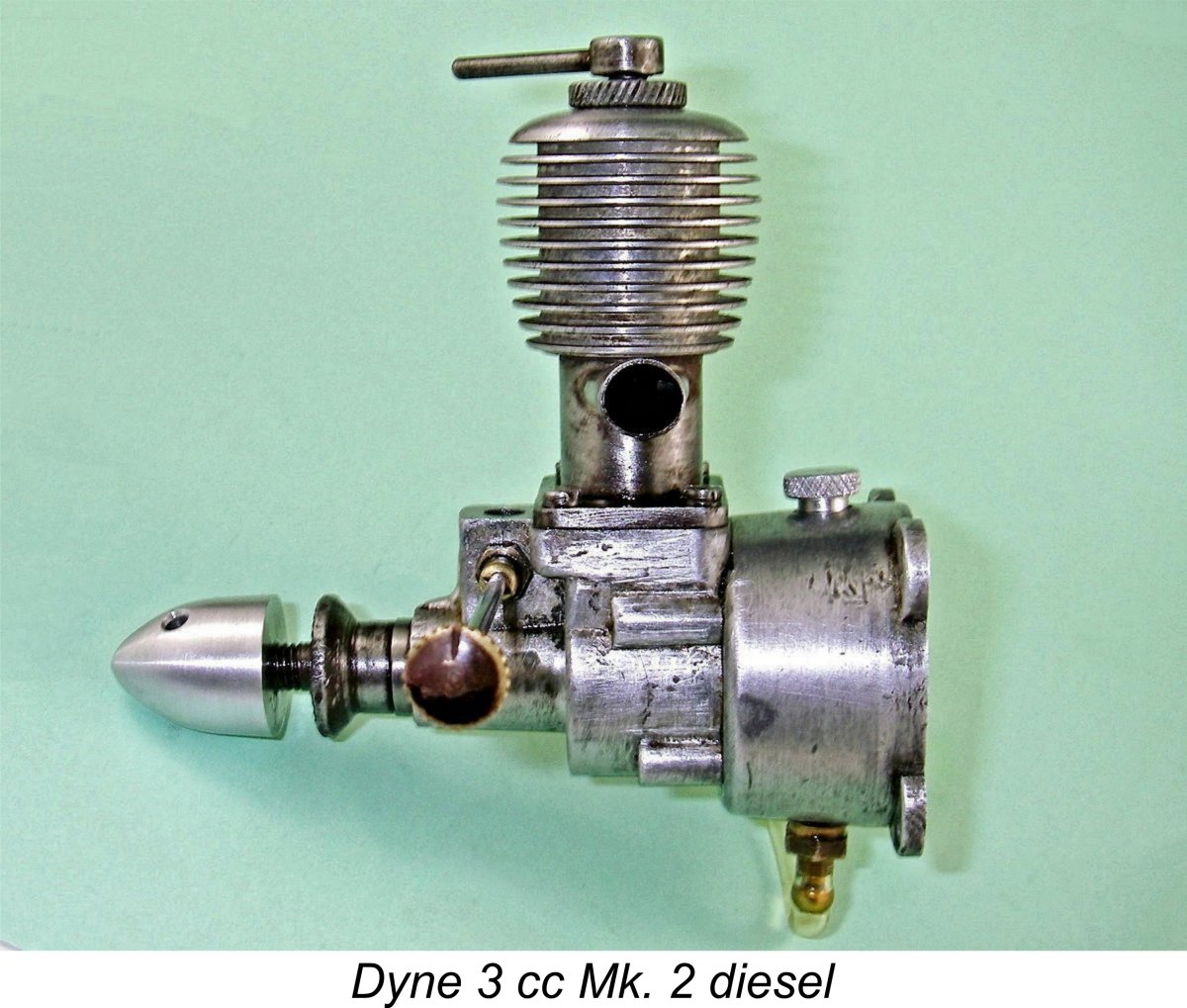 K. The issue was resolvable using the approach that I adopted, although it was a significant hassle and in any case wouldn't have worked if the Jagra control valve had been fitted.
 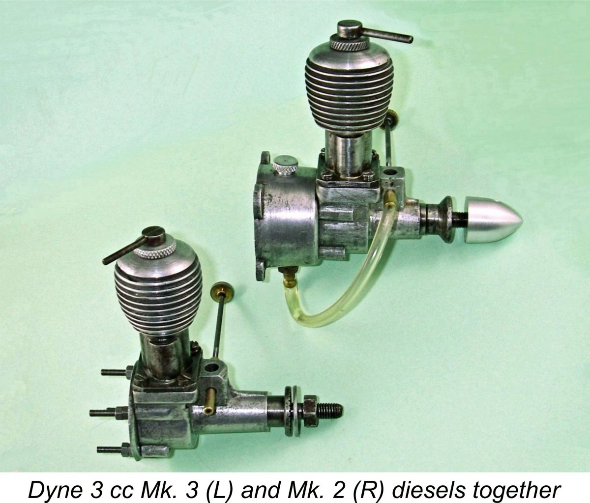 Regardless of the amount of use which it may have received prior to 1951, the engine remained in absolutely first-class mechanical condition throughout. Like the other example described previously, it undeniably presented a somewhat rough 'n ready external appearance to the world! However, there was no mistaking the quality of its construction where it really counted. Piston/cylinder fit in particular was outstanding, nor was there any significant play in the rod assemby. I anticipated little trouble in getting it going and extracting a fully representative performance.
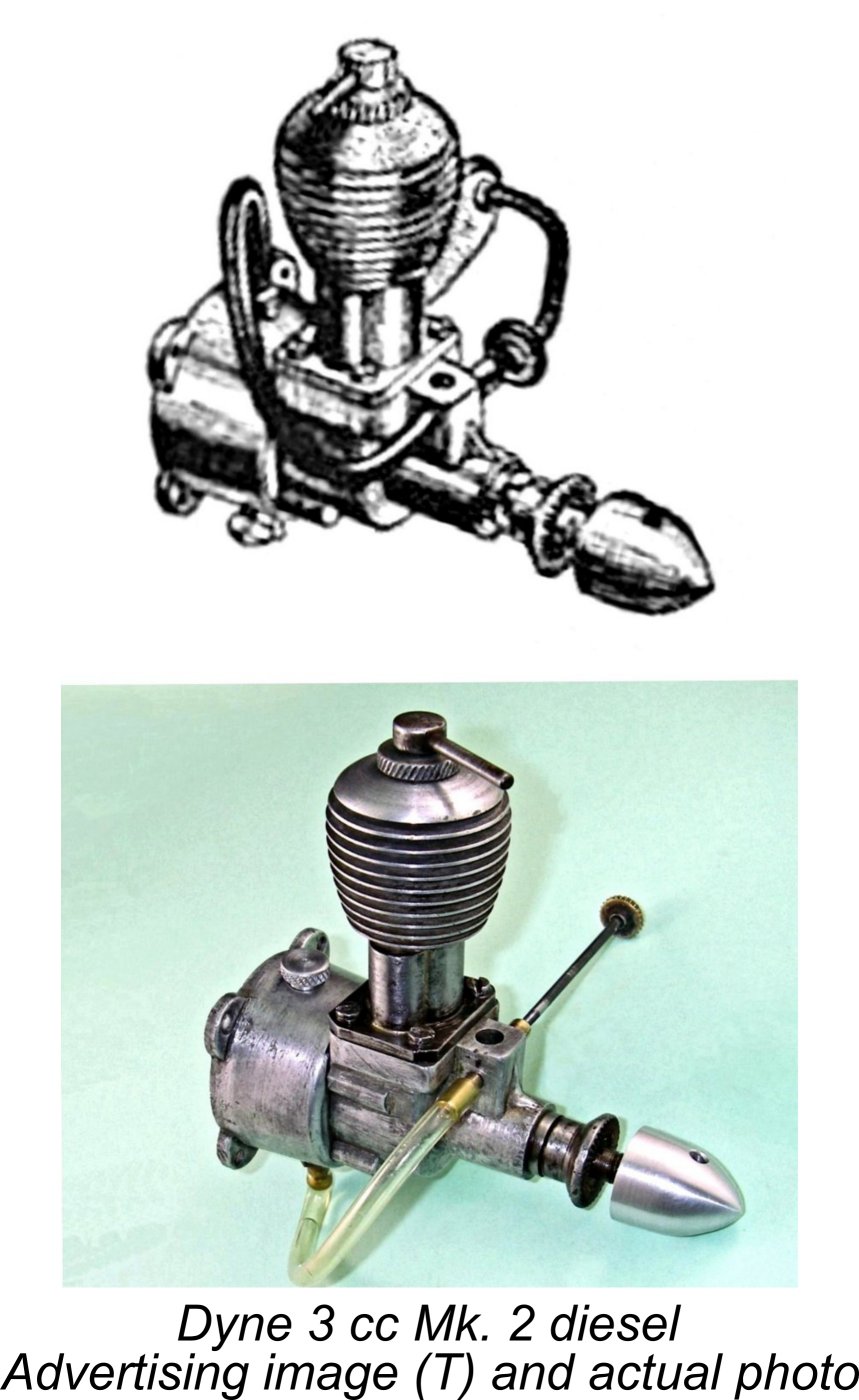 As stated earlier, the tankless engine appears to be an example of the control-line variant of the Mk. 3 Dyne 3 cc diesel. When it comes to the eBay example with its tank, there seems to be little doubt that it is an example of the Mk. 2 variant. The truncated length of the main bearing housing (by comparison with the Mk. 1, Mk. 3 and Mk. 5 versions) with the end of the main bearing sleeve protruding from the front is a dead giveaway. The accompaying comparison of this example with the advertising image which was specifically identified by Watkins as the Mk. 2 version seems to me to put this identification beyond doubt. The fact that its bypass passage and exhaust stack are silver-soldered in place sets it apart from the other example, as does the use of a spinner nut instead of a hex nut and washer.
 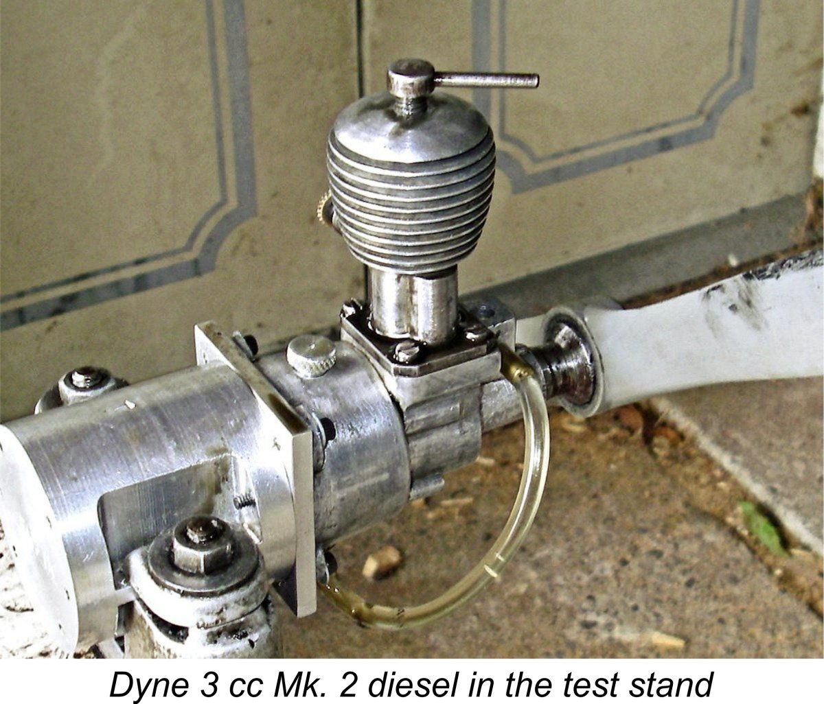 OK, so much for the predictive power of theory - how does actual practise stack up? The induction timing numbers measured from the Mk. 3 example with its cobbled-up crankshaft made no sense at all (hence not being reported here), nor did they compare in any way with the very rational figures for the Mk. 2. I therefore decided to restrict my initial testing to the Mk. 2 example pending the manufacture of a new properly-timed crankshaft for the Mk. 3 unit. Accordingly, I set up the Mk. 2 example with its tank mount, fitted an 11x6 APC prop and got stuck in!
  So far it all sounds rosy, doesn’t it?!? Well, that’s about the end of the good points! The first thing that became apparent was the engine’s status as a vibration producer – it really shook the old test stand! The fact that it was in effect cantilevered out to the front of the actual stand didn’t help, but even so the levels of vibration that I encountered were pretty severe. The lack of clarity in the attached image of the engine running isn’t down to my admittedly marginal photographic skills but to the fact that the engine was very much in vibratory mode!
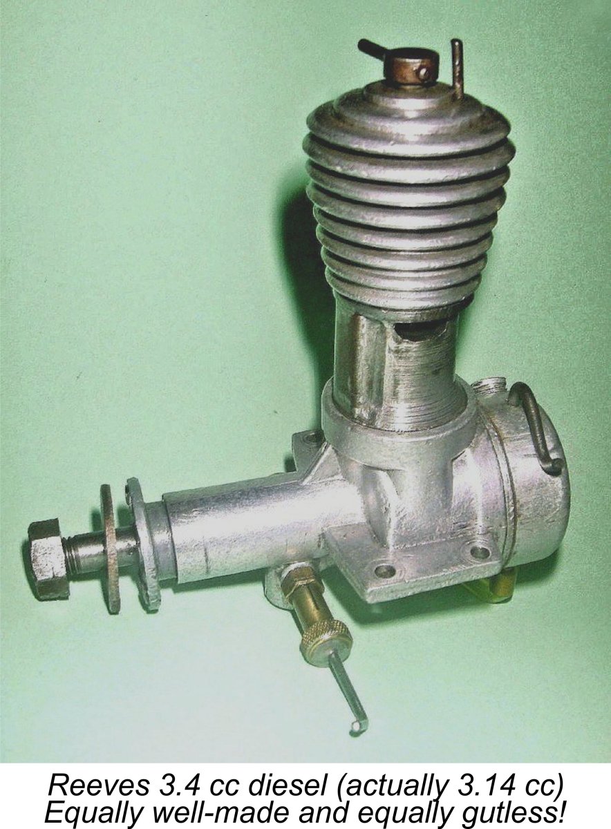 The only contemporary diesel of comparable ineffectiveness with which I have personal experience is the equally agricultural-looking but very well-made
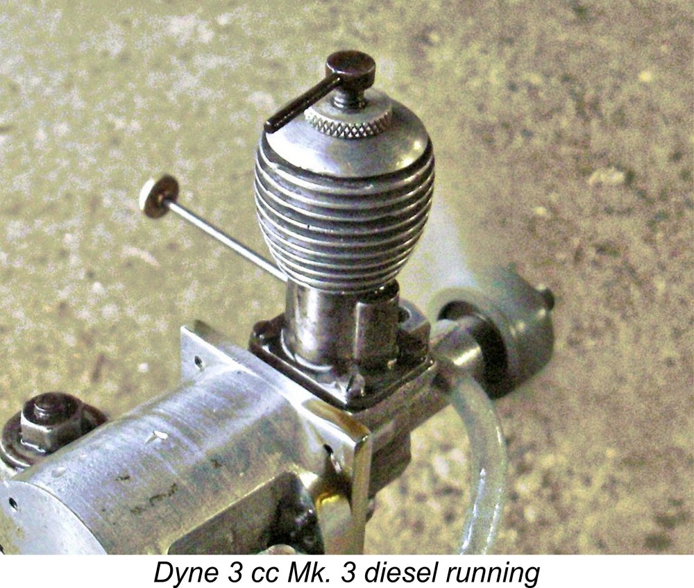
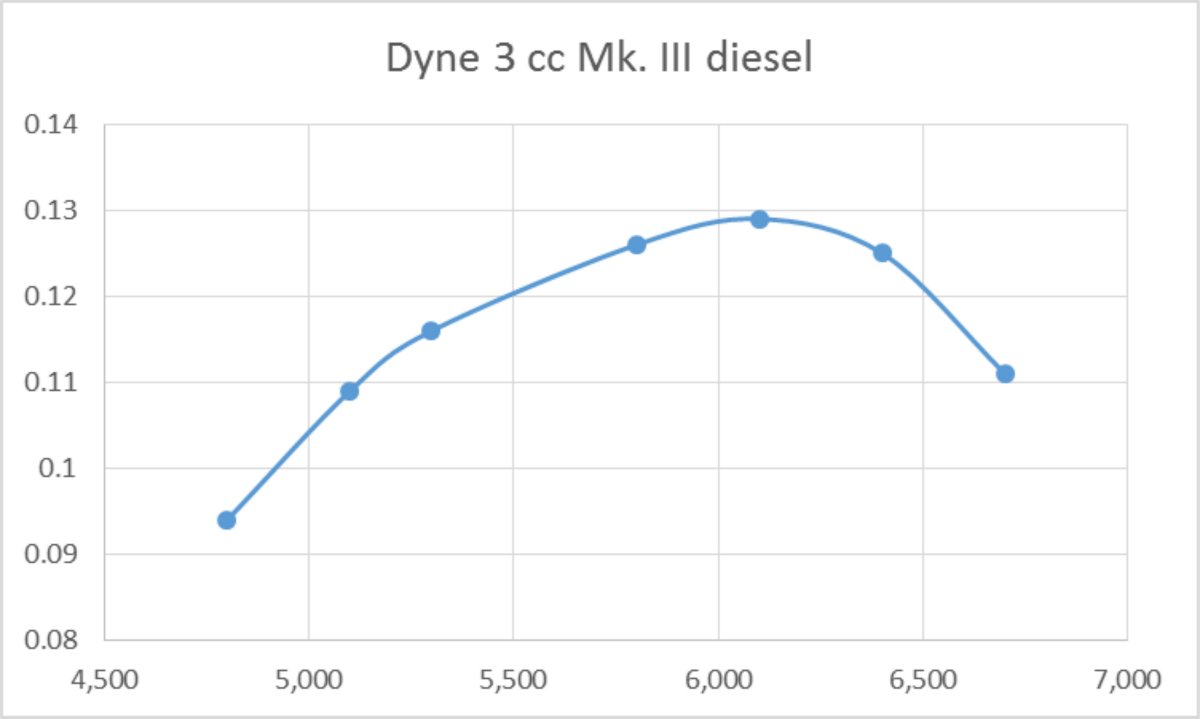
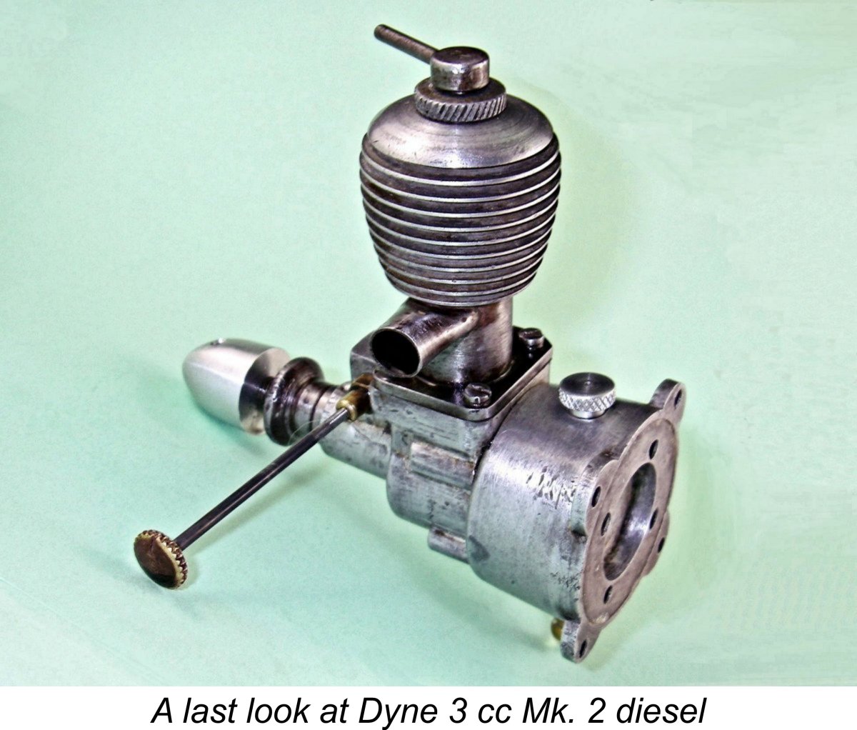 2.8 model,
 | |