
|
|
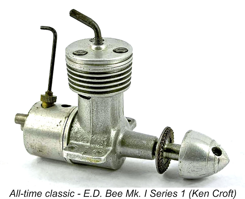
The E.D. 1 cc "Bee"- the “Engine with a Sting” By Adrian Duncan with Ron Chernich
It's a toss-up which of these names, if any, stands preeminent among the rest. However, a strong claim can be made for that status being occupied by the subject of this article, the 1 cc E.D. Mk. I Bee, a name which is instantly recognizable to any model diesel engine enthusiast. This humble little diesel probably did more than any other E.D. engine to lay the foundation for the success of the E.D. company during the 1950’s. It’s certainly among my own favourites – a Series 2 Bee was my very first new diesel engine, way back in 1959! It served me well.......
Ron’s excellent and very informative article has doubtless filled this need admirably in the 20-plus years since its 2004 publication. Unfortunately, my greatly-missed mate Ron left us in early 2014 without passing on the access codes to his heavily encrypted site. Consequently, no maintenance or updating of that site has since been possible, making it inevitable that a slow but inexorable process of deterioration is taking place over time. It’s this issue that has led me to transfer a number of what I consider to be the more broadly relevant articles over to my own site. This is one of them. Ron’s article is sufficiently comprehensive that the information which it contains merits preservation in full. However, I felt that it would benefit from a certain degree of reorganization. Moreover, Ron omitted a fair amount of information which I considered relevant to the subject. Accordingly, the text of the following article should be read as an amalgam of Ron’s original comments and my own observations, with a few corrections and additions which appeared to me to be desirable. Having set the stage, it’s time to review the background to the appearance of this iconic model diesel engine. Background
Suffice it to say that E.D. produced some of Britain’s first commercial compression ignition (“diesel”) engines as well as the first commercial radio control outfits to go on sale in quantity in the UK. For a considerable time, their product offerings were prolific and well respected both domestically and in European and Commonwealth countries. Consequently, they achieved a prominent position in the buoyant British model industry catering to the "air-minded" youth of the 1950's. This was particularly true of the range of model engines which they manufactured.
Although E.D. managed to resume production at a reduced level, they were unable to regain their market position, fading fairly quickly from the scene thereafter. The last engine sold under the banner of the “original” E.D. company was the excellent but short-lived 1.5 cc “Hawk”of 1963, which was actually manufactured off-shore by Webra. Returning now to the early days at E.D., the company had been established It was reportedly Basil Miles, already a very well-known figure in the fields of model engineering and tethered hydroplane racing, who persuaded E.D. management that there was a bright future to be pursued through the company’s entry into the field of model engine production. Miles’ friend and fellow Malden hydroplane racing club member Charlie Cray was apparently retained initially as their chief designer, although Miles evidently maintained a close background connection through his association with Cray. With Cray apparently serving as the primary designer, the E.D. company entered the model engine field in early 1947 with their famous 2 cc E.D. Mk. II “stovepipe” model. In late 1947 this was joined by the even more famous 2 cc Comp Special. In early 1948 the All three of the models introduced to this point by E.D. had retained the somewhat primitive “stovepipe” cylinder configuration which had first appeared on the Mk. II. These engines bore little imprint of Basil Miles’ design style, being far less conceptually advanced than most of the engines which had been developed previously by Miles on his own account since 1936. Moreover, the Mk. II in particular embodied a number of design shortcomings which seem highly unlikely to have escaped the attention of a model engineer of Miles' calibre. It thus appears probable that Charlie Cray was primarily responsible for these designs. However, the same could not be said of the next E.D. model to appear! This was the 1 cc E.D. Mk. I Bee (the "Engine with a Sting") which forms the main subject of this article. This considerably more sophisticated design seems far more likely to have benefited from Miles’ design expertise than any of its predecessors. However, before we get into that, it seems appropriate to pause for a moment to consider E.D.s approach to the naming and enumeration of their engines. E.D.’s “Mark” Series Designations and Serial Numbers The nomenclature used by E.D. during this early period was rather confusing at first sight. Our central subject, the E.D. Bee, was designated from the outset as the “Mk. I” model. However, we shall see that the Bee didn’t enter series production until August 1948. This was well after the appearance of both the Mk. II in March 1947 and the Mk. III in March 1948! And it might have been even more confusing if cooler heads had not prevailed – my mate Kevin Richards has irrefutable evidence in the form of a boxed example that the Comp Special of December 1947 was originally intended to be known as the Mk. III 2 cc model!! The label on the box clearly shows both the model designation as Mk. III and the displacement as 2.00 cc.
In this scenario, the Mk. II was released as soon as possible in order to generate some doubtless-needed cash flow, leaving the Mk. I designation available for the future 1 cc design whenever it was ready. As matters turned out, even the Mk. III beat the Mk. I into the field, as noted earlier. On the surface this looks reasonable enough, doesn’t it? However, Kevin Richards has presented a persuasive argument to the effect that matters were almost certainly more convoluted than this! It’s actually far more probable that the decision to designate the original 2 cc model as the Mk. II was nothing more than a marketing ploy to convince the public that considerable development of the original 2 cc model had already taken place. The original plan to designate the Comp Special as the Mk. III 2 cc model is completely consistent with this notion since it clearly implies the prior existence of Mk. I and Mk. II versions of the company's 2 cc offering. If this scenario is correct, as seems highly likely to me, then the fact that there was a gap in the Mark sequence to accommodate the far later Bee was entirely fortuitous. Since it certainly doesn’t take 18 months to develop a simple engine like the Bee from scratch, it appears highly likely that the decision to develop the Bee was made long after the Mk. II was well and truly launched. The fact that the Bee first appeared in prototype form in April/May 1948 strongly suggests that the decision to develop that model was most likely taken in late 1947, more or less concurrently with the release of the Comp Special.
The fact that the improved 2 cc engine was never advertised as anything other than the Competition Special suggests that the boxed Mk. III 2 cc models were part of the stock build-up run which preceded the announcement of any new engine for which brisk sales were anticipated. That run was probably manufactured in November 1947. Having now discussed the genesis of the engine’s official designation as the E.D. Mk. I, it remains to provide some comment upon the serial numbering system applied to the company’s model engines. The serial numbers used by E.D. were more like a coding scheme than a sequence, hence appearing rather "opaque" to the uninitiated. In reality, the system is unusually informative, each sequence being unique to the type of engine, the year and month of production and the position of the engine within that month’s production sequence. Can't get any more informative than that! The system used by E.D. is fully explained in my separate article covering the E.D. story. Suffice it to say here that the E.D. numbering system began with either a letter or a single-digit number indicating the particular model of that engine. The letter W before the model indicator denoted a watercooled marine example. The model indicator was followed by a second letter indicating the month of production, followed by the number of the engine in that month’s batch. The letters I and L were omitted from the otherwise-alphabetical month indicator sequence (A for January, etc.), presumably to avoid confusion with the number 1 and with an erroneously-struck inverted 7 respectively. The sequence was completed by an indication of the year of production. Confusingly, this indication sometimes appeared after the month indicator as opposed to the end of the sequence. The original version of the E.D. Bee, the so-called “Mk. I Series 1” model, was assigned the numeral “1” as its model designator. So for example, E.D. Bee no. 1J 163/8 was a Mk. I Series 1 example which was the 163rd Bee manufactured during September 1948. Subsequent variants of the Bee were assigned different model identifiers. We’ll discuss those changes in their appropriate place in what follows. The E.D. "Bee" Series - General Comments
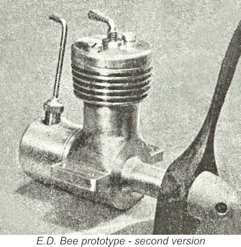
Oddly enough, the early E.D. advertisements for the Bee depicted this prototype model rather than the production version. Remarkably, that image survived in the advertising until February 1949, when a single-armed compression screw was shown in place of the former thumbwheel. However, the engine was still depicted as having a two-bolt head. A close examination of that advertising image shows that the compression screw was apparently sketched onto the earlier thumbwheel image of the same engine, along with a somewhat fanciful pair of "bee's wings"! It wasn’t until March 1949 that the Bee was finally shown in its familiar 3-bolt form. Despite this advertising confusion, the reality is that the two-bolt engine was never actually put into series production, serving entirely as a prototype. It is believed that only a very few examples of this style The Bee appeared in production form in late August 1948. As a disc rear rotary valve (RRV) induction diesel having near-square internal geometry (i.e., bore and stroke close to equal), it was quite an advanced engine for its time in a domestic market previously dominated by long-stroke side-port models. Indeed, the design of the Bee represents a radical step forward from the preceding E.D. “stovepipe” designs. It’s this observation that leads one to the strong suspicion that Basil Miles was beginning to exert an ever-stronger albeit still unacknowledged influence upon E.D.’s design efforts. In this context, it’s interesting to note Kevin Richards' well-informed comment that Miles’ name is conspicuous by its absence from any known listing of the company Directors - indeed, Kevin confirmed that available company records show no evidence whatsoever that he held a managerial or staff position within E.D. at any time. Nor does he appear to have been one of the original working shareholders. It appears that his design work for E.D. was conducted all along on a contractual or royalty basis.
The lack of acknowledgement seems to have rankled with Miles, since he appears to have designed the next model to appear, the iconic E.D. Mk. III Series 2 Racer of March 1951, with the stipulation that he was to be openly credited with its design. E.D. complied with this requirement, making the Racer the first commercial model engine for which Miles was given full credit. OK, back to the Bee! Time now to commence our review of the various renditions of the E.D. Mk. I Bee which appeared during the engine’s 14-year production lifetime. The manufacturer assigned Series numbers to the major versions of the Bee, but we’ll have to go a little further in order to differentiate between the various sub-variants which appeared under the same Series designation. It must be clearly understood that the letter designations which distinguish the different variants of the same Series are mine and mine alone, having nothing to do with any manufacturer designations. They are used here purely for convenience in the context of this article. Another point that should be noted at the outset is the fact that most components are directly interchangeable between the various renditions of the engines within the same Series. Accordingly, many examples exist which display elements of more than one of the listed variants. I've done my best to sort out the different variants, but exceptions and anomalies will undoubtedly be encountered. The E.D. Bee Mk. I Series 1A
Whether or not Basil Miles was involved with its design, the Mk. I Bee represented a clear technical advance in the context of E.D.’s model engine range. It featured over-square internal geometry, disc rear rotary valve (RRV) induction and well-considered cylinder porting which allowed for a degree of overlap between the transfer and exhaust ports. As a general overriding comment, all variants of the Series I Bee are readily identified “across the room” by having the cooling fins turned integral with the gravity die-cast crankcase together with rear-facing exhaust ports. The crankcases used initially were produced from a gravity mold which was split vertically through the crankcase at right angles to the shaft axis. The initial version of the engine, which I have called the Series 1A variant, had four fins below the thicker uppermost flange which accommodated the threads for the three 6BA head screws. Bore and stroke of the original Bee were 0.437 in. (11.10 mm) and 0.400 in. (10.16 mm) for a slightly over-square bore/stroke ratio of 1.09 to 1 and a calculated displacement of 0.983 cc (0.06 cuin.). These dimensions were to be maintained throughout the entire Bee series. As illustrated, the engine weighed in at a checked 2.82 ounces (80 gm) complete with metal back tank. The cylinder porting was quite innovative for a British diesel of the period. The transfer ports consisted of two 3/32 in. diameter holes drilled through the cylinder liner at a steep upward angle and placed at the front at an appropriate spacing. These ports overlapped the exhaust ports to a considerable extent. They were supplied with mixture by two bypass channels milled into the interior wall of the upper crankcase. Two oval-sectioned exhaust ports discharged at an angle towards the rear of the engine, one on each side. In effect, the Bee was a rear exhaust cross-flow loop scavenged design lacking the usual piston baffle.
In addition, three small indentations were machined into the rim of the cylinder location flange at 120 degree intervals. The head screws engaged with these indentations, thus ensuring that the ports remained correctly aligned at all times since the liner could not be wrongly installed or rotate during operation. Moreover, the liner would necessarily be returned to its precise original alignment following any disassembly and re-installation procedure. This would do much to minimize any incremental additional wear which might result from any unavoidable dismantling for servicing. From the outset, the Bee sported a plain turned three-bolt head and a single-armed L-shaped compression screw, advertising images to the contrary. The comp screw operated in an unusually fine 1/8-40 Whitworth thread. The 4BA left-hand prop installation thread which had been featured on the prototype shafts was changed to a right-hand thread, possibly to guard against the shafts being broken by over-tightening while an uninformed owner was trying to loosen a seemingly-stuck prop-nut! The shaft journal diameter was increased at the same time over that of the prototype – it seems that a few lessons had already been learned!
The rotor disc appeared to have been stamped from 1/8 in. thick aluminium sheet and was permanently riveted to the turned screw-in backplate. The fuel tank was a neat and quite sturdy aluminium stamping which was retained by a machined aluminium alloy bolt. The tank was suitable only for use in an upright mounting configuration. The intake duct was a simple steel tube which was a firm plug fit into a hole in the backplate. The spraybar was soldered in place rather than being secured by a nut in the conventional manner. The intake had an internal diameter of 0.156 in. (4.0 mm), while the spraybar had a working diameter of 2.5 mm. This combination results in a choke area at the spraybar location of 3.262 mm2, which is somewhat excessive for consistent operation at the relatively moderate speeds of which the 0.98 cc Bee is capable, although it does favour enhanced top end performance. Maris Dislers has found that the Bee performs far more consistently in use with a retro-fitted spraybar of slightly larger diameter. Nonetheless, these dimensions were to be retained throughout the entire E.D. Bee series. One point which seems to have escaped the attention of many owners is that of needle valve tensioning. It will be observed that there’s no ratchet or external coil spring to encourage the needle to retain its setting. In reality, the brass thimble is spring-tensioned, but this takes the form of a very small internal coil spring which fits around the actual needle and is small enough to slide all the way into the internally-threaded cavity of the thimble, where it effectively disappears! Being completely out of sight, many owners are not even aware of its presence, and it’s often missing from surviving examples. Check to see if yours is still there! The disc rear rotary valve would excite no particular comment if it weren’t for the fact that it’s used in conjunction with a screw-in backplate. This means that the location of the inlet cannot be determined and machined until a backplate is screwed into a given crankcase. Once that’s done, the backplate can be drilled for the venturi tube, but will only be in the correct orientation for that particular backplate/crankcase pair, which therefore have to remain together thereafter. This form of construction makes reassembly a bit of a chore. Place the conrod on the crankpin with the piston fitted and the shaft, sans the prop-driver at this stage, set at TDC. Then place the rotor so that the blind hole for the crankpin is in line with the venturi. Screw the backplate into the case until it is close to the crankpin with the venturi oriented at the "12 o'clock" position. Now push the shaft back and jiggle it to engage the rotor, squinting down the case opening as required to ensure it has been inserted into the blind hole and not the rotor inlet opening! The backplate can now be screwed all the way in, pushing the shaft forward, and normal assembly can be resumed. In a word, painful! However, once assembled correctly, the system works well enough. T This gap was sufficient to allow the shaft to move rearward to the point where the end of the crankpin bore against the inner base of its shallow driving socket in the disc valve rotor (see above image of the disc valve). This meant that any rearward pressure exerted on the shaft, whether during starting, through pusher operation or in a crash, would be transferred directly to the disc, which would then act as a thrust bearing or an impact absorber. Not what the designer intended, and not at all good for longevity!! The correct arrangement is to limit the shaft end float to the extent that any rearward pressure on the shaft is resisted by the front of the main bearing pressing against the rear of the prop driver, leaving the valve disc free from axial pressures.
Based on the 3-view drawings which accompanied the test report, it appears that it was one of these variants which was the subject of subject of Lawerence Sparey's 18th engine review for “Aeromodeller” which appeared in the October 1949 issue. Sparey liked the engine very much, reporting a peak output of 0.061 BHP at 10,500 RPM. He commented particularly upon the engine’s compact size and easy-starting nature. Being a "traditional" long-stroke man at heart, he also went on at some length about the near-square short-stroke design, expressing mild surprise that this feature had not imposed any obvious detrimental effect, then explaining in some detail why common wisdom of the time leaned towards long-stroke designs.
Suffice it to say here that the Mk. I Series 1A Bee as released in late August 1948 was an excellent performer by then-current standards, also possessing outstanding handling qualities. My own At some stage during the production of the Mk. I Series 1A Bee, an experiment was conducted with a crankshaft front rotary valve (FRV) version of the engine. Reader Steve Betney provided some images of a prototype FRV Bee in his possession. This unit is clearly based upon a cast Mk. I Series 1A crankcase, implying that it post-dates the introduction of that model. However, the experiment doesn't appear to have been a success, since nothing was ever heard of any intention to manufacture an FRV version of the Bee. The standard E.D. Bee Mk. I Series 1A model seems to have remained in production for only a few months. Even so, a substantial number of examples must have been produced during that period - Brian's Cox's engine no. 1J 370/8 confirms that at least 370 examples were manufactured in September 1948 alone. Whatever the true figure, this is probably the least commonly-encountered production version of the E.D. Bee. The E.D. Bee Mk. I Series 1B
The casting was now amended to replace the stamped-on vertical ED lettering on the bypass with the same letters cast in relief within a rectangle in the same location on the case, while the serial numbers were relocated to the lower crankcase, just beneath the left-hand mounting lug. Both of these features are clearly visible in the accompanying image. At some point prior to March 1949 the serial numbers were The Series 1B variant seems to have remained in production throughout the balance of 1949. Interestingly enough, some examples of this variant featured a needle valve fitted with a brass knob in place of the more usual bent wire - my little-used engine no. 1J 704/9 from September 1949 has this type of needle valve control. Again, this very minor change doesn't appear to me to warrant the identification of a distinct variant. However, at some point in early 1950 the manufacturers moved to address what had clearly been identified as a weakness in the original design of the E.D. Bee. This resulted in the next unarguably distinct variant to be discussed - the E.D. Bee Mk. I Series 1C. The E.D. Bee Mk. I Series 1C
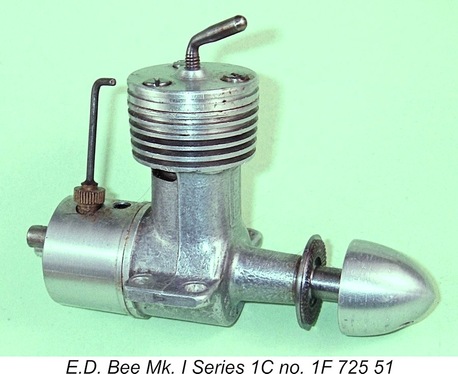
The manufacturer’s solution was to increase the thickness of the upper flange by eliminating one of the cooling fins. The same casting remained in use, but there were now only three such fins to go along with a significantly thicker top flange. This allowed the use of fasteners having considerably greater threaded lengths to engage with the deeper holes in the upper flange – far less prone to stripping. In all other respects, this variant was unchanged from its predecessors. One might feel some concern regarding the loss of cooling fin area resulting from this change. However, the Bee was not a particularly hot-running engine, and the reduced cooling area does not appear to have made any noticeable difference to the engine’s operating characteristics. This variant remained in production well into 1951 - illustrated engine no. 1F 725 51 from June 1951 underscores this observation. However, at some point prior to November 1951 a few more relatively minor changes were made, resulting in the next variant to be discussed. The E.D. Bee Mk. I Series 1D
In my own opinion and that of many others, this was a retrograde step - the plastic tanks almost invariably leaked, also becoming cracked or distorted over time. I considered the original metal tanks to be greatly superior. Their replacement with an inferior component was likely a cost-cutting measure. In addition, the rather skimpy 1/8-40 Whitworth thread for the compression screw was enlarged to a far more rational 4BA. A conventional T-shaped tommy bar comp screw now replaced the former single-armed component. My illustrated New-in-Box example no. 1M 489/51 from November 1951 exemplifies these latter changes, which had no effect upon the engine’s functional arrangements. It appears that at least one minor sub-variant of this engine may exist. My valued friend and informant Gordon Beeby of Australia tells me that he owns engine number 1F 127/52 from June 1952, which looks exactly like a Mk. I Series 1D model apart from having exhaust openings in the crankcase casting which are cut with square ends rather than the usual rounded terminations. Gordon is fairly certain that these do not represent an owner intervention but are as supplied by the factory. There appear to be no other changes. I'd guess that either this was a production experiment which failed to prove its worth, or perhaps a few such engines were produced during a period when the equipment used to cut the rounded apertures was unavailable for some reason. I'd be interested to learn if any more such examples are lurking out there! The E.D. Bee Mk. I Series 1E
We saw that the original castings were produced by gravity casting using a die which was split vertically through the crankcase at right angles to the shaft axis, with the engine’s ED designation being first stamped and then cast onto the front face of the bypass. The mold used to produce the cases was now changed to a three-component assembly.
The same components were also used from the outset in the construction of the companion 1.46 cc model, which appeared in early 1953 and was subsequently christened the Hornet. It used the same casting apart from the substitution of 1.46 for 1.00 on the right side of the case. Naturally, the machining of this casting to produce the Hornet differed from that applied in the construction of the Bee. In this form, the Mk. I Series 1 Bee was to remain in production until mid-1955. We’ll consider its eventual replacement next. The E.D. Bee Mk I Series 2 - General Comments
The crankcase, cylinder, head and backplate were all extensively revised, with the cast components now being produced by pressure die-casting, allowing thinner sections and very fine detail. The new crankcase sported a side stack very reminiscent of then-conventional glow motor design practice. The case-hardened steel cylinder liner carried integral fins along with totally revised porting. About the only externally recognizable components carried over from the Series 1 version were the needle valve, comp screw, spinner nut and prop driver! In fact, apart from the general RRV design and the unchanged bore/stroke dimensions, the Series 2 Bee could be viewed quite legitimately as a completely different engine! It would not have been out of line for the manufacturers to re-name it accordingly. However, the name “E.D. Bee” had acquired considerable name recognition value after some 7 years, an asset upon which the manufacturers naturally wished to capitalize.
Ignoring the obvious external differences, the general arrangement of the new variant remained basically similar to that of its predecessor. The hardened and ground one-piece steel shaft remained unbalanced and unbushed – in fact, it appeared to be the same shaft. The rotor disk was still stamped aluminium, and the cast iron piston was still flat-topped. Initially, even the hardened steel conrod was retained, although this was changed at a fairly early stage to a forged aluminium alloy component. A sound move - forging can impart a 50% strength increase to aluminium alloy, while alloy-on-steel wears far better than steel-on-steel. E.D. must have decided by this time that individually-fitted and drilled screw-in RRV backplates were for the birds, since the Series 2 variants used a rear cover which was retained by four 6BA cheese-head screws. Serial numbers were now stamped on the end of the left side mounting lug. Over time, the E.D. Bee Mk. I Series 2 model appeared in three quite distinct variants. Let’s review those variants in turn. The E.D. Bee Mk. I Series 2A
However, the major functional feature that distinguished this variant from its successors was its transfer system. Bypass and transfer were effected by two internal channels formed in the lower inner cylinder wall on the left hand side. Twin exhaust ports were cut through the cylinder wall on the opposite right-hand side. The latter ports discharged through the previously-mentioned side stack. The transfer ports overlapped the exhaust to a significant extent. These cylinder porting arrangements were a precise reflection of the configuration which had been used from the outset in the companion 3.46 cc E.D. Mk. IV "Hunter". “Aeromodeller” published a test of the early Series 2A Bee in their September 1955 issue. By this time, “Aeromodeller” engine tests were being conducted by Ron Warring using the eddy current Warring took note of the unbalanced crank, quaintly commenting that "This is undoubtedly one of those engines which will give its smoothest performance with a slightly unbalanced propeller, the heaviest blade being set opposite the piston at top dead centre" (!) and going on to note that vibration caused problems with both eddy-current dynamometer and torque-reaction testing rigs. Warring felt that the integral tank design requiring long unsupported engine bearers might well have exacerbated the perceived vibration problem. Most oddly, he also observed that the four-bolt backplate made it impossible to alter induction timing by rotating the backplate - not something I'd have thought to try! Since they were only in production for about a year, the Q-series engines are among the less commonly encountered variants of the E.D. Bee models. The E.D. Bee Mk. I Series 2B
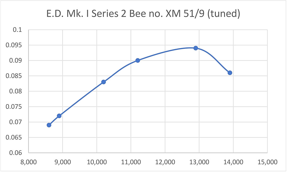
Internally, the major change centered once again on the bypass and transfer arrangements. The two internally-formed bypass/transfer channels were now replaced with three 3/32 in. diameter transfer ports which were drilled through the cylinder wall at a steep upward angle from the outside. These ports were supplied with mixture by three bypass channels formed in the exterior of the lower cylinder wall. The transfers overlapped the exhaust to a considerable degree. In all other respects, the engine remained unchanged. However, once again it appears that E.D. themselves understandably viewed these modifications as being significant enough to warrant another change in the model identification letter. The engines featuring the revised transfer arrangements were assigned the model identification letter “X”. An example of this model was the first new over-the-counter diesel that I ever owned - engine no. XM 51/9 from November 1959, which was a much-appreciated gift from my parents at Christmas 1959. I still have this engine, although it's missing its tank and bears the evidence of some of my youthful pre-collector misdemeanours (filed front webs, shortened stack). After some difficulties in learning to start the engine, due entirely to inexperience, it served me well, especially after I tuned it some years later to release substantially more power (see below). It still runs remarkably strongly! I've recounted the efforts of my long-suffering Dad in getting on top of the starting issue in a separate article which may be found in the Readers' Recollections pages on this website.
Chinn’s report provided an excellent description of the changes, observing that of the two models tried, the later Series 2B model was the more pleasant to handle, being less critical of adjustments. The performance curves included in Chinn’s report (left) indicated a maximum output of 0.064 BHP @ 10,700 rpm – more or less identical to the performance reported by Warring for the Series 2A variant. Chinn also commented on the change to the main bearing housing, claiming that it resulted in a ".... stiffer main bearing housing, the bearing itself now being bushed with a special alloy developed for this particular purpose." Strangely, no example of this model which I’ve had a chance to examine has shown any visible evidence of such a bushing, unless it is the casting alloy itself. A test of my own E.D. Bee Mk. I Series 2B no. XJ 247 9 (September 1959) conducted in support of this article more or less confirmed the published figures. This example is essentially unmodified but has been "fettled" - dismantled, internally cleaned up a little and re-assembled very carefully. It's also had a fair bit of previous use, hence being very well run-in. Possibly as a result, it did a little better than Chinn's example, as the following data show:
The implied peak output of 0.074 BHP @ 10,500 RPM is generally well in line with published figures. It's noteworthy that these tests all found the peak output lying in the 10,500 - 11,000 RPM speed range. A 7x5 airscrew would appear to be an ideal match. Just for fun as well as to satisfy my curiosity, during the writing of this article I also tested my old tuned E.D. Bee Mk. I Series 2B no. XM 51/9 (made in November 1959). This one is well into its first rebore, but started and ran as well as ever, demonstrating very clearly why it surprised a few people back in the day! It generated the following data on test:
The above data imply a peak output of around 0.095 BHP @ 12,700 RPM - a considerable step up from published test figures for the unmodified engine, and actually encroaching well into A-M 10 territory. No wonder that I had so much fun with this engine and surprised a few people in the process! If nothing else, the performance of my tuned E.D. Bee Mk. I Series 2 unit confirmed that a good deal of untapped potential remained in the design. However, it wasn't until 1960 that the company took any steps to realize this potential. When they finally did so, the results were remarkable! The E.D. Bee Mk. I Series 2C The variant of the E.D. Bee just described continued to be a steady seller for the company, being particularly favoured by beginners and casual sport flyers. It remained in production until 1960, still being manufactured in considerable numbers throughout its four-year production period. However, by 1960 there were unmistakable signs that E.D. was in the process of becoming one of “yesterday’s companies”. By and large, their model engine designs were falling increasingly behind the times. They appear to have severed their connection with Basil Miles in 1958, subsequently hiring Gordon Cornell to attempt to bring their designs and production methods more up to date. However, a combination of insufficient development funding and personality clashes between Gordon and E.D. management doomed this effort to eventual failure.
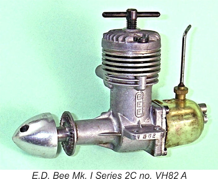
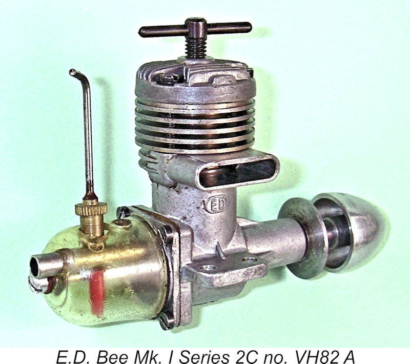
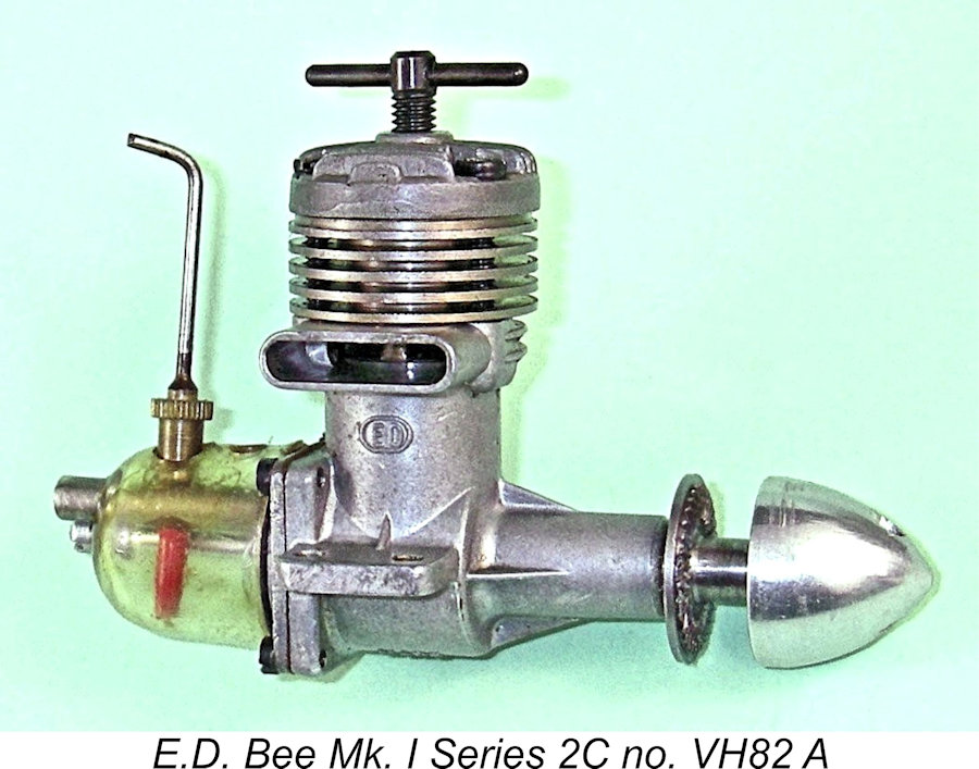
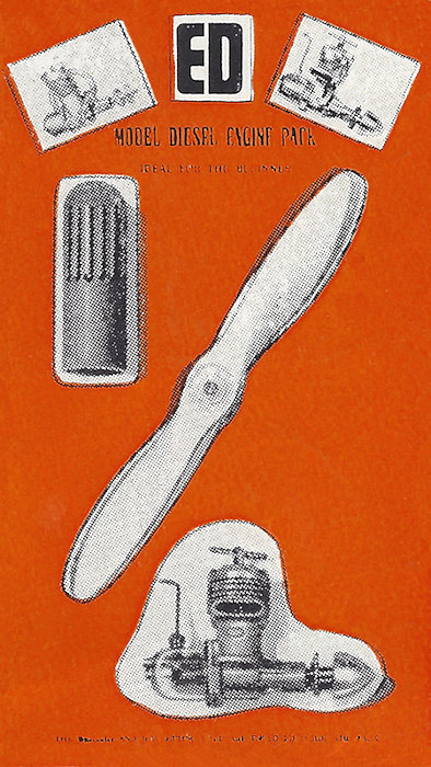
In 1960, in an effort to rehabilitate the Bee in the eyes of the modelling public, Gordon Cornell comprehensively revamped a number of features, most notably the transfer porting, to produce a vastly-improved performer that was in every way an out-of-the-box match for such highly-regarded competing 1 cc diesels as the A-M 10 and FROG 100 Mk. II. The most significant modification was a major enhancement of the bypass and transfer arrangements. The former three 3/32 in. diameter The four transfer ports were supplied by a greatly enlarged bypass created by tapering the outer wall of the lower cylinder below the cylinder installation flange. The lower cylinder wall was also shortened a little to improve gas access to the bypass. To complement these changes, the piston was lightened somewhat by appropriate machining, while the crankshaft journal was diametrically “waisted” slightly in its central length to reduce friction. Finally, some examples featured a non-metallic disc along Another significant innovation which appeared at this time was a move towards more "American-style" packaging. In addition to being sold in a box like all the other E.D. models, the Mk. I Series 2C Bee was also offered in a card-backed bubble pack (left) which included a finger-stall and a matching airscrew. This combination was evidently targeted at beginners. The contemporary Pep 0.81 cc model was offered in similar packaging at the same time. Kevin Richards recalled that his very first new engine was Mk. I Series 2C Bee no. VK 410 A (October 1960), which arrived in its bubble pack on Christmas Day, 1960. These were obviously significant changes. E.D. clearly agreed with this appraisal, recognizing their significance by the application of yet another model identification letter, this time the letter “V”. The new variant was undoubtedly in production by August 1960, as proved by illustrated engine number VH 82/A from that month.
It’s quite clear from Chinn’s assessment that E.D. had a real winner on their hands here - Cornell had put the sting back into the Bee with a vengeance! This being the case, it's a completely inexplicable fact that E.D.’s advertising failed to so much as mention the existence of this revised model and its vastly improved performance. On the contrary, they Consequently, the modelling public remained for the most part in blissful ignorance of the vastly improved Bee unless they happened to either read Chinn’s test report or see one of the new models in operation. I was one of those unfortunates - since I was an "Aeromodeller" subscriber, I never saw Chinn's test report until much later, long after the Bee was history. Unfortunately, in the absence of any promotional effort by the manufacturers, the Bee’s reputation as a dependable but less-than-stellar performer was too well entrenched by this time for the performance of the relatively few examples of the revised model which reached the flying field to restore the engine’s former popularity. Hence the greatly enhanced design really didn’t have much impact upon the waning fortunes of the E.D. enterprise - another clear and totally inexplicable case of lost opportunity.
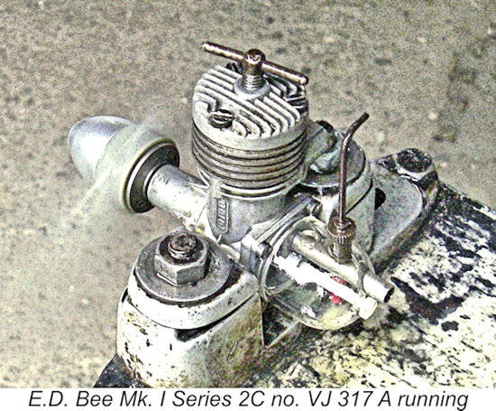
While writing up this article, I put a few runs on Mk. I Series 2C engine number VJ 317 A from September 1960. This very pleasant break from writing reminded me once again just how good a 1 cc diesel of its era this was. In terms of prop/RPM figures, it actually beat my previously-cited tuned Mk. I Series 2B engine number XM 51/9, although not by that much. Generally speaking, its performance seemed to match that reported by Chinn quite closely. Mind you, it also upheld the E.D. reputation by sporting the usual seriously leaky tank! The trick was to put fuel in the tank, start the engine immediately while some fuel remained in the tank, refill the tank with the engine running and then stand clear of the trail of atomized fuel leakage picked up by the slipstream. Probably only half of the fuel supplied was actually consumed by the Bee! Still, the engine started and ran very well indeed. The cited serial numbers combine to show that the engine was still selling reasonably well at this time, being produced in substantial quantities on a monthly basis throughout this variant's production lifetime of perhaps eighteen months or so - it appears that as many as 5,000 examples may have been produced in total. Even so, Bees in this form are relatively uncommon today by comparison with other Bee variants, hence being quite highly prized among knowledgeable collectors and vintage fliers. They are undoubtedly very strong runners by the standards of their day – definitely the best-performing Bees by far. So at least the Bee went out on a high note! Under-Appreciated Replacement - the E.D. Cadet There’s no question that the original E.D. company was struggling as of the early 1960’s. They had lost the services of Gordon Cornell in late 1960, thus needing to find a replacement engine designer/production manager. The late 1961 decision by International Model Aircraft to abandon the manufacture of their FROG range of engines left the very experienced George Fletcher looking for a job, an opportunity of which E.D. took immediate advantage.
Sadly, we’ll never know what impact Fletcher’s arrival and the implied planned changes in the company's direction might jointly have had upon the further evolution of E.D.’s model engine range. On April 29th, 1962, shortly after Fletcher’s arrival, a major fire seriously damaged the E.D. premises at Island Farm Road. There have been tales in the past to the effect that this fire was caused by the ignition of some magnesium shavings from crankcase machining operations, but this is untrue – it had been some years since E.D. had last used magnesium castings. In reality, the fire was the result of arson committed by two youths during the course of a break-in. They were subsequently caught and convicted for this offense. We might suspect that the previously-mentioned concurrent company name change had something to do with this unhappy event. However, consideration of the editorial deadlines for the submission of advertising material for the May issues of the modelling magazines clearly implies that the name change must have preceded the fire, of which E.D. naturally had no foreknowledge. The loss of machinery, records and stock was a disaster for the already-struggling company, from which it never really recovered. However, a proportion of the vital castings and materials were salvaged along with some of the machinery. Thanks to George Fletcher’s efforts, E.D. were once again back in business soon after the fire, albeit with a substantially reduced production capacity and an increasingly truncated range. Fletcher’s initial new design for the company appeared later in 1962 in the shape of the 1 cc Cadet side-port diesel, complete with a very The Cadet was an adaptation of the E.D. Bee crankcase and working components to a sideport design. It was specifically intended to demonstrate the feasibility of sport-flying in urban environments using an extremely quiet low-powered engine having characteristics well suited to beginners. One very positive feature was the long-overdue return of the metal tank!
The induction port was particularly interesting. The cylinder port was a simple sawn slot, which was a poor match for the round hole through which mixture passed through the intake venturi into the crankcase. A simple slot placed centrally at the rear of the cylinder wall would have provided a rather inadequate cylinder induction port area. To get around this without interfering with the rear bypass channel, the slot which formed the actual induction port was extended assymetrically to the right, actually going a quarter of the way around the cylinder wall to half-overlap the single rectangular exhaust port above it. An interesting design! A thoughtful detail was the care taken to ensure that the cylinder was installed in the one correct annular orientation in which it would function as designed. A couple of sawn indentations were placed in the bottom edge of the cylinder wall to indicate the left and right sides. These may be seen in the image above at the right. In addition, the cylinder's installation flange featured three shallow indentations in its outer edge at the locations of the three hold-down screws, preventing the screws from engaging with their tapped holes unless the cylinder was correctly oriented. Again, one of these intentations may be seen clearly at the left in the above image. The engine was fitted with the type of spring starter However, one of the consequences of the fire was a significant erosion of E.D.’s ability to maintain adequate quality control, leading to serious quality inconsistencies with the earlier examples of the Cadet (notably a tendency towards marginal compression seal and poor main bearing fits) which prevented some of them from running at all! Gordon Beeby recalled having once owned a second-hand Cadet in which the cylinder bypass channels were cut so far out of their design alignment that the rear channel intersected the crankcase induction passage, preventing the engine from running. If the cylinder was rotated in the case to eliminate this overlap, the engine would run but half of the exhaust port then became obscured by the case. In addition, the main bearing was so loosely fitted that a substantial discrepancy was created between the starting and running compression settings, added to which crankpin and big end wear were greatly accelerated. To cap it all, the backplate was warped to the point that it wouldn't seal properly. OUCH!! Even those that did run were woefully lacking in peak power by comparison with most of the other 1 cc sports diesels then available. George Fletcher instituted measures to eliminate the worst of the quality issues, also developing a Mk. II version having revised porting. This variant was announced in the "Motor Mart" feature in the November 1963 issue of "Aeromodeller". It reportedly performed far more consistently at a somewhat higher level, but the Cadet never managed the kind of performance that it took to excite the marketplace of the day. In any case, since E.D. themselves never publicized the existence of this stronger-running version of the Cadet, very few aeromodellers even knew about it.
In the end, the main problem was one of marketplace perception rather than any shortcomings in the engine itself. The Cadet has generally been roundly condemned in the past as a gutless paperweight, but people both then and later tended to overlook the fact that the engine actually did exactly what it was designed to do - start easily and swing a sizeable airscrew at extremely low noise levels. E.D. have often been ridiculed for introducing the Cadet, but the reasoning behind its introduction was both logical and compelling. Which would you rather have - a low-powered dead-quiet engine that the Council will allow you to use; or a more powerful but noisier model that they won't?!? Unfortunately, most people completely overlooked the engine's very laudable purpose, viewing it as just another 1 cc sports diesel like all the others. Consequently, owners tended to under-prop the engine, failing to recognize that as a side-port design with a restricted exhaust system, torque at lower speeds would obviously be its strong suit. On larger props, the Cadet was quite comparable with many of its competitors, but few contemporary modellers appreciated or valued this at the time. Kevin Richards told me that his original Cadet as tested by Chinn and Warring flew a Performance Kits Apex (42 in. wingspan) quite satisfactorily using an 8x4 prop.
In retrospect, the Cadet’s reputation is particularly unfortunate because its performance deficiencies were actually very easily overcome. In a review which appeared in the February 2020 issue of “Aero Modeller” magazine, Maris Dislers showed that the major reason for the Cadet’s mediocre performance was the use of a standard E.D. needle valve assembly featuring a 3.3 mm dia. spraybar which almost blocked the 4.1 mm I/D intake venturi, leaving a choke area of only 1.3 mm2, a quite inadequate figure for any 1 cc diesel.
Of course, there was a price to pay for this greatly improved performance. The modified engine was somewhat less impressive at lower speeds when loaded with a large propeller or when backed off for trimming. The engine was only really happy at speeds above 9,000 RPM – below that range, it seemed a little inconsistent. Carburettor blowback probably had much to do with this behavior. As a compromise, Maris turned the original 3.3 mm dia. E.D. spraybar down to 3.0 mm dia., resulting in a 2.1 mm2 choke area – still 60% larger than standard. This compromise resulted in a slightly reduced but still hefty power increase to around 0.063 BHP @ 9,800 RPM, a performance which was particularly well matched to the most practical propeller options while giving a high level of operating consistency down to 4,600 RPM. This simple modification is easily applied by any owner - you don't even need a lathe, since the same effect can be achieved by filing an opposing pair of "flats" and positioning the spraybar with the flats parallel to the venturi bore. The table Inspired by Maris's example, I tried making the same modification to the spraybar of one of my Cadets, turning the original fitting down to 3 mm diameter. Although my engine didn't respond quite as well to this tweak as Maris's unit had done, it still developed an indicated peak output of around 0.054 BHP @ 10,000 RPM when tested without the muffler. There's no question that this simple modification completely transforms the Cadet, turning it from from a marginally-useable novelty into a completely practical 1 cc sports diesel. Of course, these results say nothing about the effect which the use of the muffler would have on a modified example. I suspect that it would have a significantly greater effect on such an engine than on a standard unmodified unit, since the modified engine is capable of ingesting enough fuel mixture to generate more combustion gas than the muffler can handle. At some point I hope to create a test mounting which will allow testing of a modified Cadet with the muffler fitted. When that's done, I will add the results to this article. Based upon this showing, a properly-fitted Cadet was actually a far better design than its poorly-dimensioned needle valve assembly allowed it to demonstrate. It was only E.D.’s insistence on using the standard needle valve assembly as fitted to other models (presumably a cost-based decision) that sealed its sorry reputation. All that they had to do was turn the spraybar's working diameter down a little, but they didn't do so. Yet another inexplicable decision by E.D. …… and one that cost them.
The Cadet was the last engine from the original E.D. company to reach the market. The later E.D. Hawk was actually a badge-engineered Webra product, while the very impressive Condor 10 cc R/C glow-plug model never made it past the prototype stage. A series of E.D. ownership and manufacturing changes began in 1963, leaving George Fletcher once more out of a job. According to the late Gordon Cornell, he worked for a time for Dr. Joe Ehrlich's EMC motorcycle racing venture, but that program ended in 1967 after some very fast two-stroke racing motorcycles had been produced. George's activities for many years thereafter are unknown. However, reader Paul Goodenough encountered George much later in 1982, at which time he was employed as the chief technician in the Medical Physics mechanical workshop at Leicester University Medical School. Sadly, George succumbed to cancer only a few years later. A Clone from Far, Far Away - the O.S. "Bee"
Prior to 1957, the O.S. company had shown very little interest in diesels as far as the rest of the world was aware. However, it appears that company founder Shigeo Ogawa somehow got hold of an example of the Mk. I Series 1C E.D. Bee and decided to have a go at replicating it for the Japanese domestic market. This was a bit of a leap into uncharted marketing territory - as far as can be ascertained, this was the very first model diesel from a domestic source to appear commercially on the Japanese market, thus being a real novelty in that context. The engine doesn't seem to have been a huge success - based on reported serial numbers, it appears that perhaps 500 examples at most ended up being made in total.
A detailed review and test of this very rare engine may be found elsewhere on this website. Suffice it to say here that the Japanese clone is just as well-made as the original E.D. product, also starting very easily and running extremely smoothly. My test example was actually somewhat on the tight side, possibly explaining why it didn't quite come up to the reported performance levels of the original. However, it was a promising first try at diesel manufacture on the part of O.S. founder Shigeo Ogawa, also representing a very sincere compliment to the E.D. design upon which it was based. The 150,000th Bee vs. the 300,000 Claim
In its April 1954 issue which appeared on the stands in mid-March, “Aeromodeller” magazine announced that the 150,000th Bee would “soon” be sold. The image confirmed that the engine in question would be a Series 1E model. The lucky owner was to receive the princely sum of ten pounds (not so shabby when you realize that this was nearly four time the price of a single engine). As seen in the announcement reproduced at the right from the inner back cover of the magazine's April 1954 issue, the winner was to be matched against the serial number of the 150,000th engine. This number was apparently already known to Jim Donald, E.D.’s Managing Director, but was being kept strictly under wraps. The result was scheduled to appear in the June issue, by which time the engine in question was expected to have been sold. Well, June arrived with a rather obscure entry in the Trade Notes column delaying the announcement to the July issue. We can speculate that serial number returns were slower than anticipated, or even that the awaited number just never showed up in sales records or warranty registrations - not every purchaser bothered to register. When the announcement did appear in the July issue (again in Trade Notes), it gave the name of the Now, we’ve already seen that the Series 2 Bee appeared in July 1955, being announced in the company's previously-reproduced advertising placement in the August 1955 issue of “Aeromodeller”. In that same August 1955 advertisement, the manufacturers included the claim that the Bee was “Britain’s most popular Diesel – over 300,000 sold”. Now, bearing in mind that E.D. had rewarded the buyer of the 150,000th Bee in July 1954, this implied that the company had sold over 150,000 Bees in the subsequent 12 months - the same number that they had sold in the previous seven years! Hmmmm…………. I don't think so! To add to the apparent promotional gobbledygook, the E.D. advertisement for September 1962 (left) was still citing an unchanged claim of “over 300,000” examples having been sold. Since that claim had first been made in mid-1955, it was getting a bit old by 1962! The September 1962 ad even included the image of the 1955 Series 2A model which had been in regular use since that model's introduction. So they didn’t sell any Bees after August 1955?!? Again, I don’t think so - the serial numbers say that they made quite a few! Heck, both Kevin Richards and I received new examples for Christmas in 1959/1960! To put us all out of our misery, the late Ron Moulton subsequently confirmed that the 300,000 figure was ultimately achieved if all versions of the Bee were included, but not until 1962, the final year of production. So the somewhat premature E.D. claim was eventually proved correct, albeit seven years after it was first made! Quite a success story despite the "elasticity" of its telling by the company! Conclusion I hope that you’ve enjoyed this look at one of the most enduring and endearing products of the British model engine manufacturing industry. The Bee made a great contribution to the aeromodelling hobby in Britain and the Commonwealth, providing many newcomers with a relatively painless introduction to power modelling. I speak with conviction here, since I was one of those beneficiaries. This is an engine that is well worthy of respect! __________________________ Article © Adrian C. Duncan, Coquitlam, British Columbia, Canada First published August 2025 Updated September 2025 - testing of modified Cadet |
||
 The Electronic Developments (E.D.) company of Surrey, England is undoubtedly one of the best-known names in British commercial model engine manufacturing history. Moreover, their practice of assigning specific names to the majority of their designs has resulted in a number of those designs achieving instant “name recognition” status among latter-day model engine aficionados. Names such as the Comp Special, the Bee, the Hunter, the Racer, the Hornet, the Baby, the Fury and the Pep conjure up instant mental images both of the engines so designated and of their manufacturer.
 Electronic Developments (Surrey) Ltd. (E.D.) burst onto the aeromodelling scene in England very shortly after the end of WW2. A detailed history of the company's rise and decline can be read in my in-depth article on the
 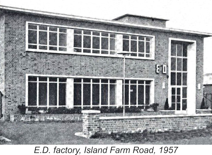 Wiser and more knowledgeable heads than mine now seem to agree that the company’s subsequent decline was fuelled by a lack of sustained R&D, increasingly poor quality control and a huge tax burden occasioned by their bet that a 1949 challenge to the application of Purchase Tax to model supplies would be successful. As detailed
 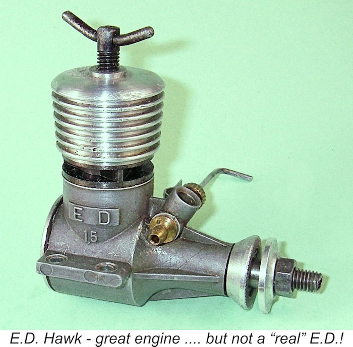 Consequently, the E.D. company’s preeminent status among British model engine manufacturers began to slip as the 1950’s drew on and gave way to the 1960’s. The final straw was the disastrous arson fire of April 1962, which destroyed much of the company’s manufacturing capability at their Island Farm Road factory in West Molesey along with most of their model engine casting dies.
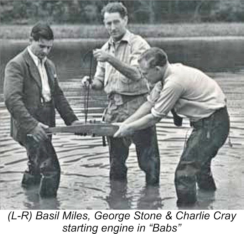
 So how do we make any sense of this? Well, although it may seem somewhat illogical at first glance, there may actually have been a degree of method in E.D.’s seeming madness, albeit perhaps as much by accident as by design! Somewhat unusually, the “Mark” numbers of E.D.'s engine range increased with displacement rather than with the order in which the designs were released. In this context, the fact that the company’s first offering chronologically was designated as their Mk. II might be taken to imply that the decision had already been taken to develop a 1 cc engine which was to be designated as the E.D. Mk. I (later to become far better-known as the Bee). However, the Mk. II design was ready 18 months ahead of the Mk. I, which first appeared in prototype form in around April/May of 1948, finally reaching the market in August 1948.
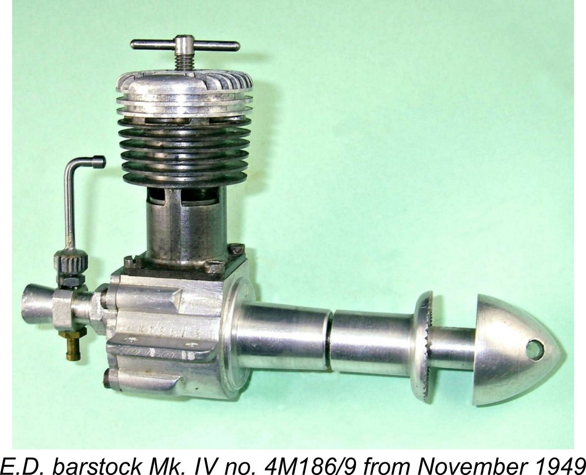 It was probably only at that stage (after a few Comp Specials had been manufactured and packaged as Mk. III’s) that some bright spark within the company belatedly recognized the promotional neatness of going up the displacement categories in step with the Mark numbers. Having come to this realization, E.D. quickly removed the Mk. III designation from the Comp Special, thus leaving that designation free to be applied to the forthcoming
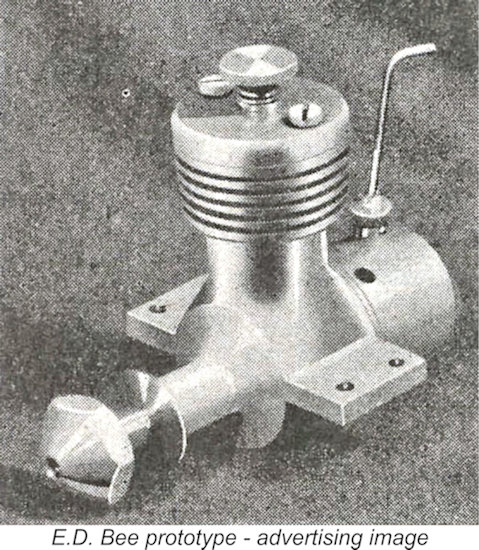
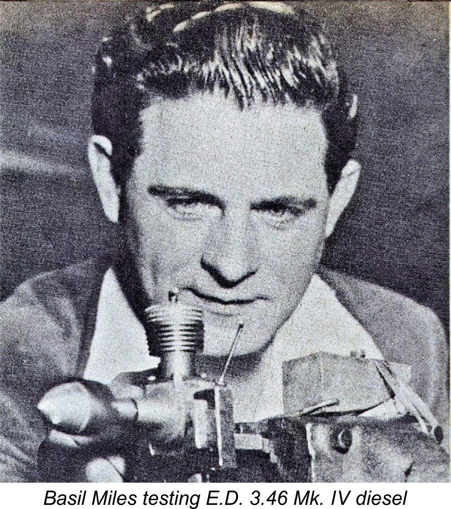 In particular, Basil Miles’ name was never associated directly with the Bee, nor am I aware of any later claim by Miles that the Bee was primarily his design. However, that doesn’t necessarily mean that he had no involvement. It certainly appears more than likely that he played a central role in the 1949 design of the later 3.46 cc E.D. Mk. IV, with which he is pictured in the accompanying illustration. However, once again E.D. never acknowledged any involvement on his part despite Miles’ later very forceful claim that the Mk. IV was his design.
 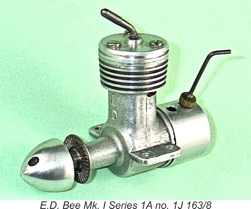 Before proceeding with this portion of the review, I must acknowledge the contribution of my friend Brian Cox, who published a very informative
 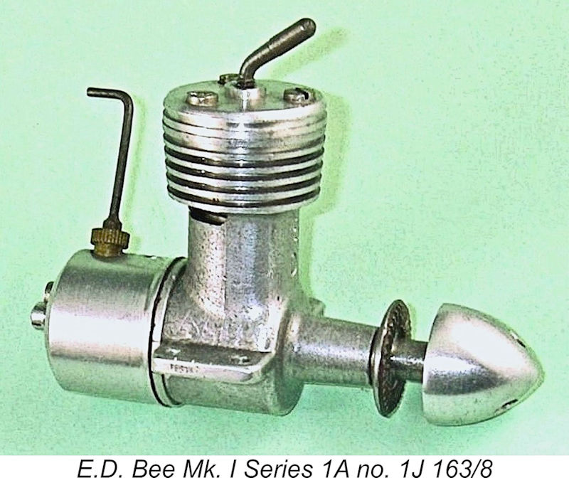 Another good feature was the positioning of the cylinder location flange at the top of the cylinder liner immediately below the head. The head bore directly upon this flange. This freed the working liner from any installation stresses, thus avoiding any possibility of distortion during assembly.
 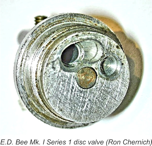 Internally, the design was quite conventional, featuring an unbalanced hardened and ground steel shaft machined in one piece and having a plain circular disc crank web. The main journal ran unbushed in the gravity die-cast aluminium main bearing which was cast integrally with the crankcase. The conrod was case-hardened steel. The flat-topped piston and contra-piston were turned from cast iron. They operated in a case-hardened steel liner.
 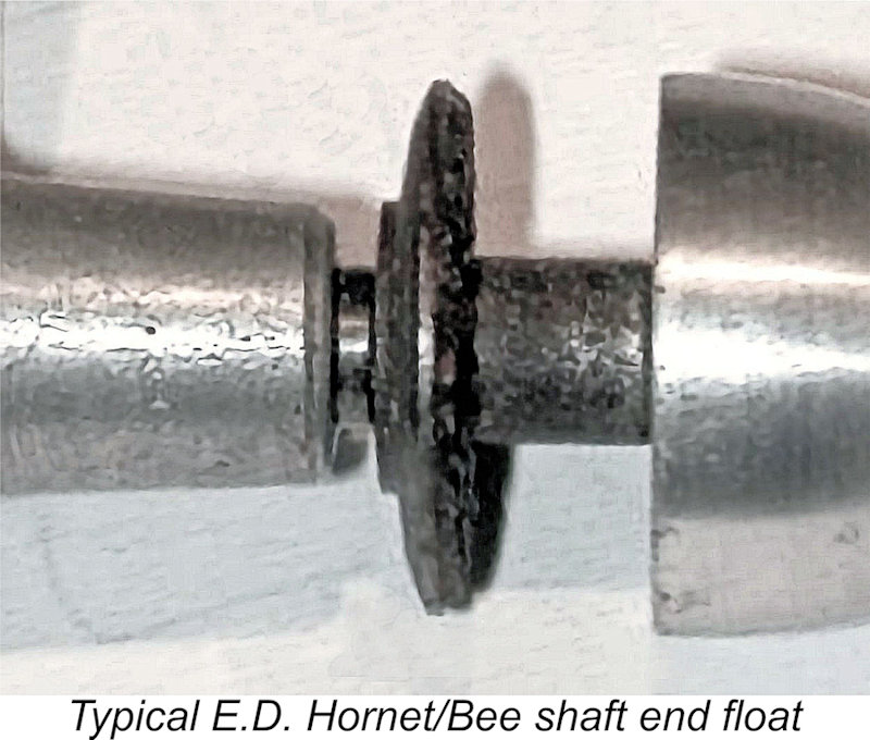 his brings us to a very important point when it comes to the correct assembly of one of these engines. The steel prop drivers used on all variants of the E.D. Bee (and on its later 1.46 cc companion in the range, the
 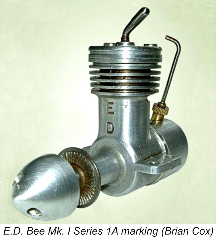 In the case of the Bee (and Hornet), the fix is either to install a steel spacer of suitable thickness between the prop driver and the main bearing or to cut the female taper in the prop driver a little deeper as required. I’ve always adopted the second of these alternatives, since it confers the added benefit of increasing the somewhat marginal length of thread which is available to engage with the light alloy spinner nut. I have a tapered reamer having the required included angle to re-cut the taper very precisely. I would strongly recommend against the long-term operation of any example of one of these engines which has not been adjusted appropriately for shaft end float.
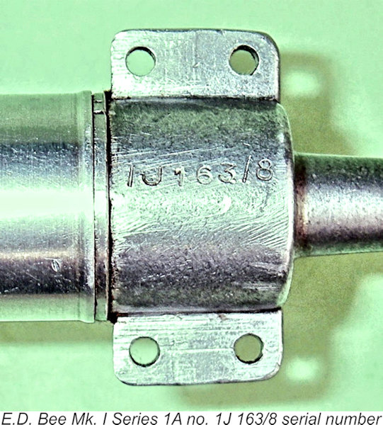 In terms of identification, the early three-bolt engines had "ED" stamped vertically onto the front of the bypass. The serial numbering sequence appeared stamped onto the base of the crankcase. These two identification characteristics define this variant, since no other version of the Series 1 Bee was marked in either of these ways.
 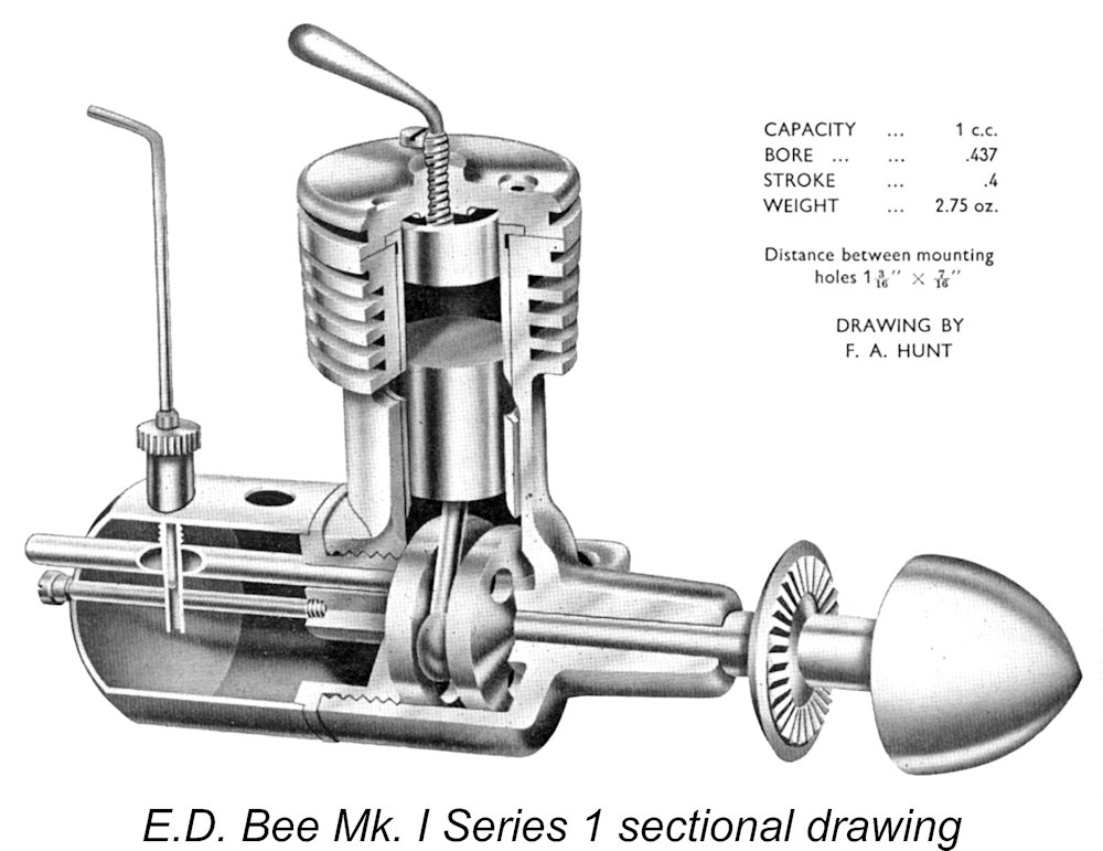 Another
 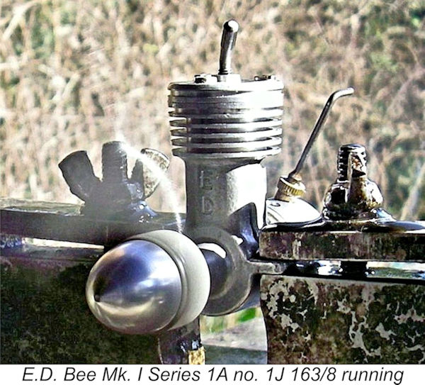 A much more recent engine test review of the Mk. I Series 1 Bee appeared in the March 1995 issue of “Model Engine World”. The BHP and torque curves in the MEW review were a little surprising, showing 0.075 BHP at 9,500 RPM compared to Sparey's “Aeromodeller” test figures - which were later condemned by “Aeromodeller” itself as overly optimistic - of 0.061 BHP at 10,500 rpm. But then ……. why not?!? This is simply another illustration of the difficulty of obtaining meaningful, repeatable and directly comparable figures for different examples of small mass-produced engines in the hands of different testers. Better to compare the numbers from a single tester using a consistent method as relative data only.
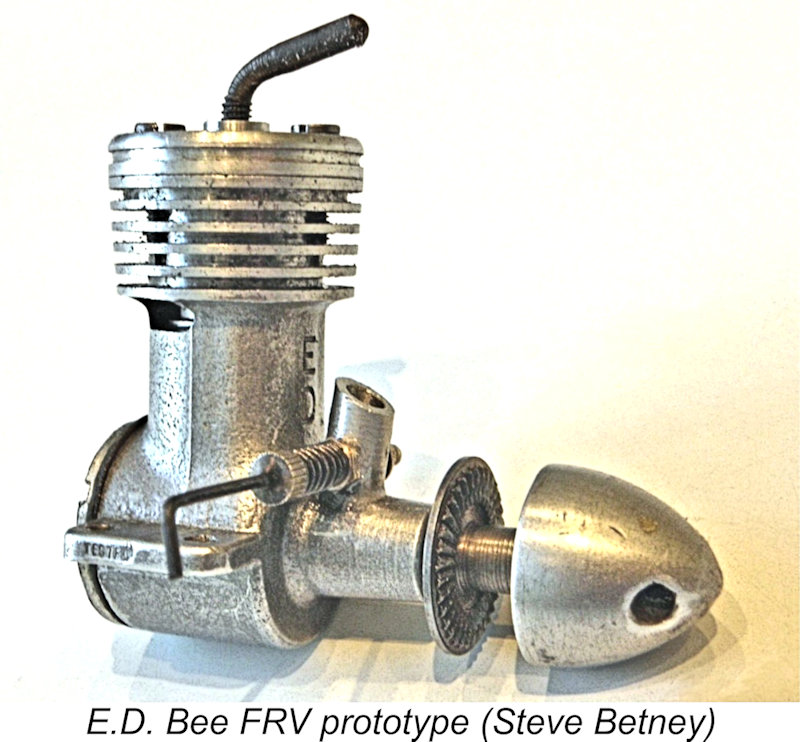
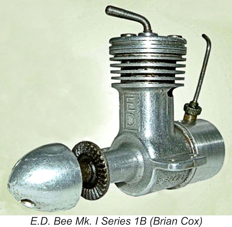 The fact that the original Series 1A variant of the Mk. I Bee only remained in production for a few months is confirmed by the early appearance of a revised crankcase casting. This change resulted in the appearance of what I've called the Mk. I Series 1B model. This variant had certainly appeared by November 1948 - Brian Cox had the illustrated Series 1B example dating from that month. The manufacturer's advertising designation of the Bee as the "Engine with a Sting" first appeared in December 1948 in connection with this model.
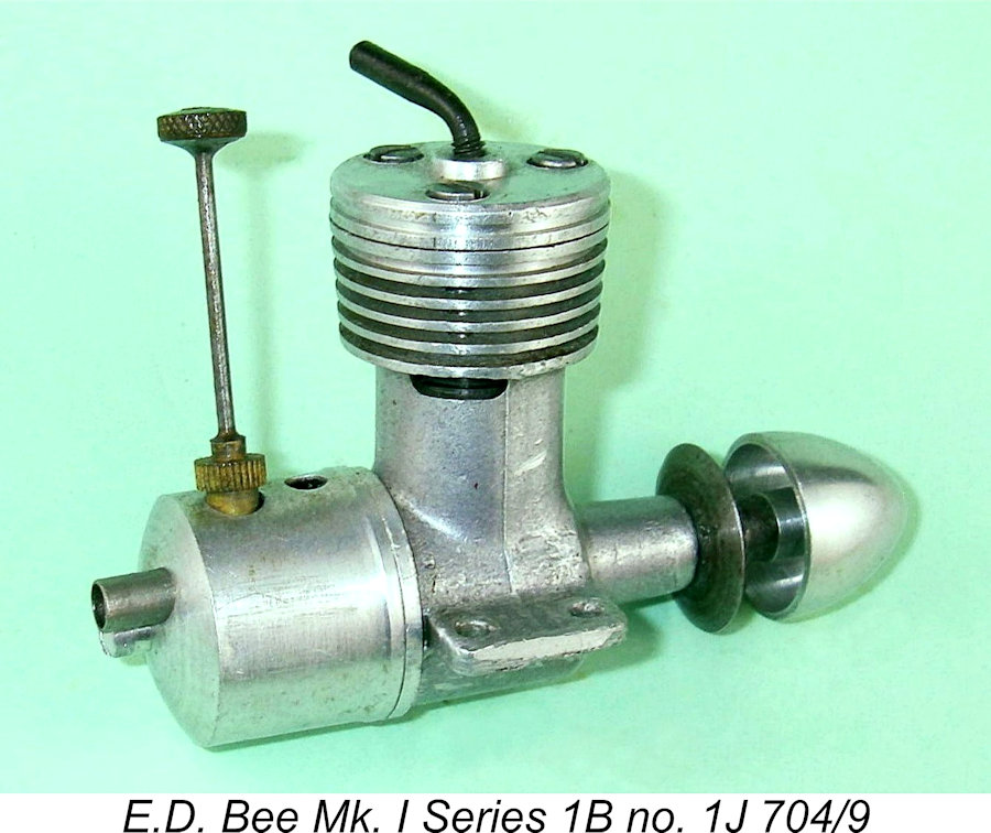
 The change which resulted in this variant centred around the relatively modest thickness of the main casting's top flange into which the threads for the three head retaining screws were tapped. It appears that problems must have been encountered with owners over-tightening the head screws to the point where the relatively short female threads which accommodated these screws became stripped. Such a level of tightness was quite unwarranted since no gas seals were dependent upon the tightness of these screws – just tight enough to prevent unscrewing during operation was quite adequate. However, those well-worn Meccano screwdrivers wielded by their enthusiastic but ham-fisted owners were more than sufficient to do the deed!
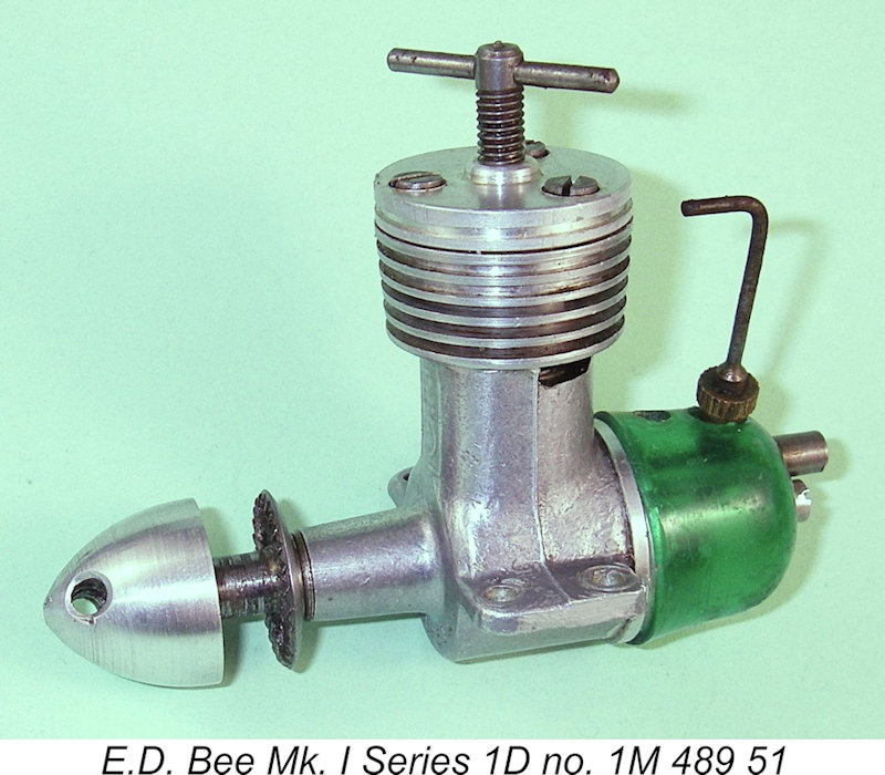 The most obvious change which defined this variant was the replacement of the stamped metal tank used previously with a tank molded from a translucent material. These tanks varied in colour between clear, pale yellow and green.
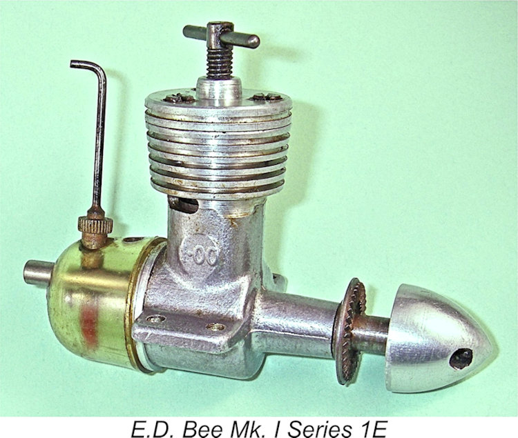 As of mid to late 1952 the E.D. company was working on the development of a 1.46 cc model which was to be based as far as possible on the use of E.D. Bee components in order to minimize tooling and manufacturing costs. A revised die was devised which would produce a casting which could be used for both models, with only a change in inserts being required to reflect the different displacements. The revised crankcases created for the Bee were utilized exclusively from early 1953 onwards once the supply of the earlier cases had been exhausted.
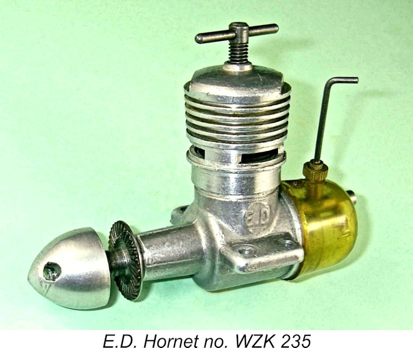 The three components of this mold were joined by a horizontal split running fore and aft along the axial centre-line of the engine, with the upper half of the case as well as its vertical extension to accommodate the cylinder being vertically split on a fore and aft plane. The new mold formed the ED letters cast in relief in a small panel on the left side of the case below exhaust level, with the figures 1.00 being cast in relief on the right-hand side of the case in the corresponding location. This variant of the Bee continued to be fitted with the translucent molded tank which had first appeared in 1951, together with the T-shaped comp screw having a 4BA thread.
 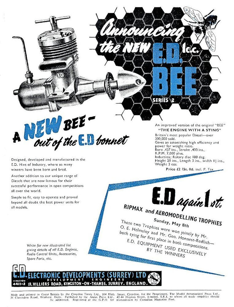 With claimed sales for the Series 1 Bee having reached over 300,000 (but see below!), a major re-design of the engine manifested itself in 1955 as the E.D. Mk. I Series 2 Bee. The initial variant of this revised model was first advertised in the August 1955 issue of “Aeromodeller”, as reproduced at the right.
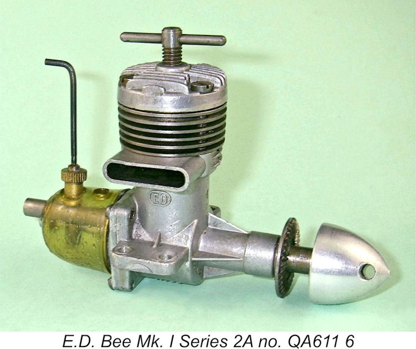 That said, the company did recognize the significance of the design changes required to produce the new variant by assigning it the model identification letter “Q” in place of the former “1” designation. Illustrated engine no. QA6 116 from January 1956 typifies this initial variant of the Series 2 Bee.
 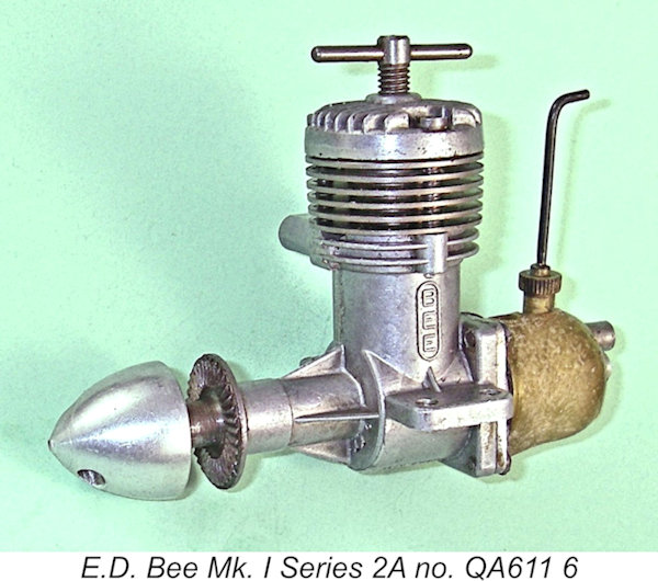 This variant was instantly recognizable by its use of a relatively skinny main bearing housing having a machined “expansion” in the “front ball race” position. It also featured a cylinder having five relatively thin integrally-machined cooling fins below the thicker top flange. It bore serial numbers which started with the letter “Q” as a model identifier.
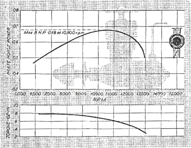 dynamometer developed for the purpose. Peak performance was quoted as 0.068 BHP at 10,900 rpm (to be taken with the usual pinch of sodium chloride) as reflected in the power curves reproduced at the left. Warring noted that the bore and stroke remained the same, also citing a weight of 3¼ ounces (92 gm) bare. He commented that this was some ½ an ounce heavier than the Series 1 version, a somewhat surprising result from a switch to pressure die-casting. Presumably the heavier finned steel liner was primarily responsible.
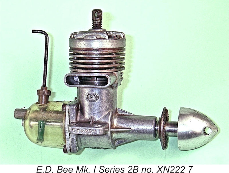 The version of the Series 2 Bee just described did not remain long in production. In mid-1956 the design of the Bee underwent a few further changes of some significance. Externally, the five thin integrally-formed cylinder cooling fins below the top flange were reduced in number to four, with each fin being a little thicker than its predecessors. The small-diameter main bearing housing with front expansion was replaced by a thicker housing having no expansion.
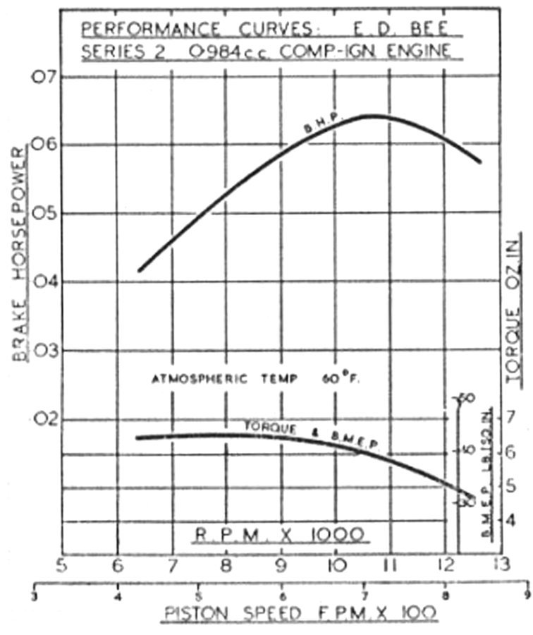 “Model Aircraft” magazine published
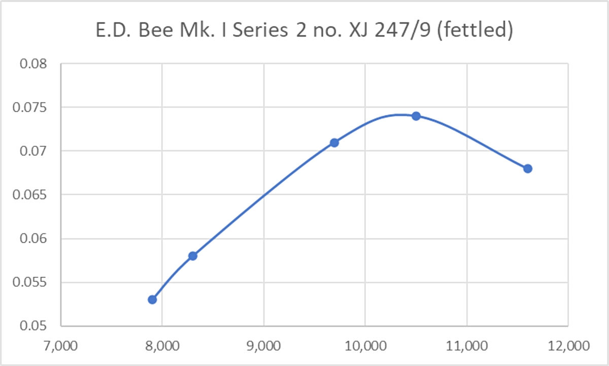
 the lines of that used in the contemporary E.D. Super Fury 1.46 cc model, while others used a pressure die-cast disc. The new offering was distinguished from its predecessors by having a light matte surface finish applied to its case and head. Some examples featured blued steel components.
 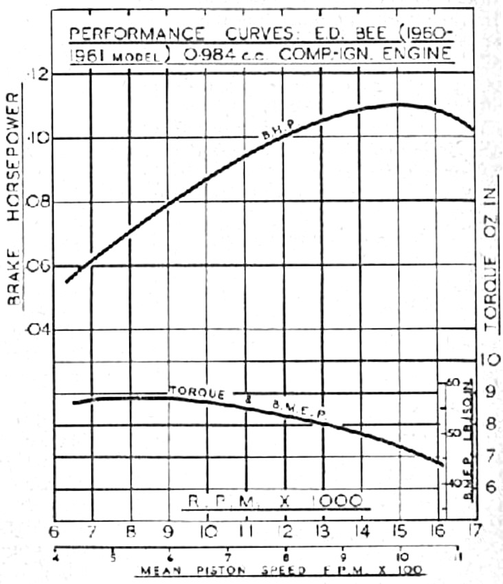 This revised version of the Bee soon attracted the attention of the ever-alert Peter Chinn. In his
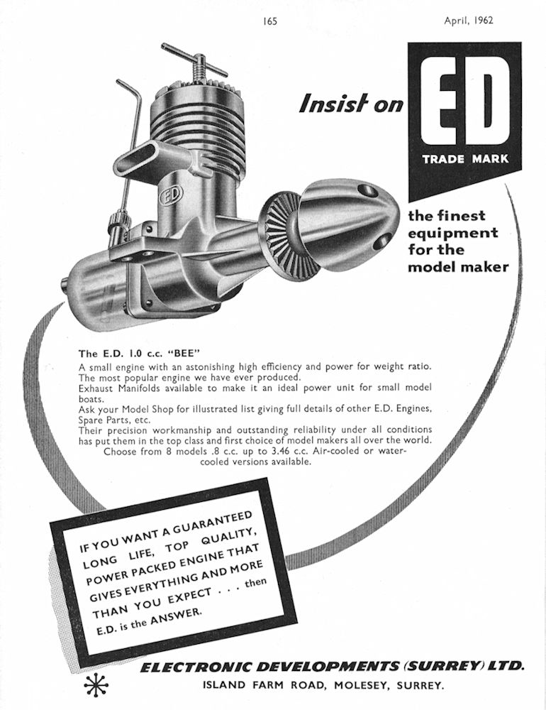
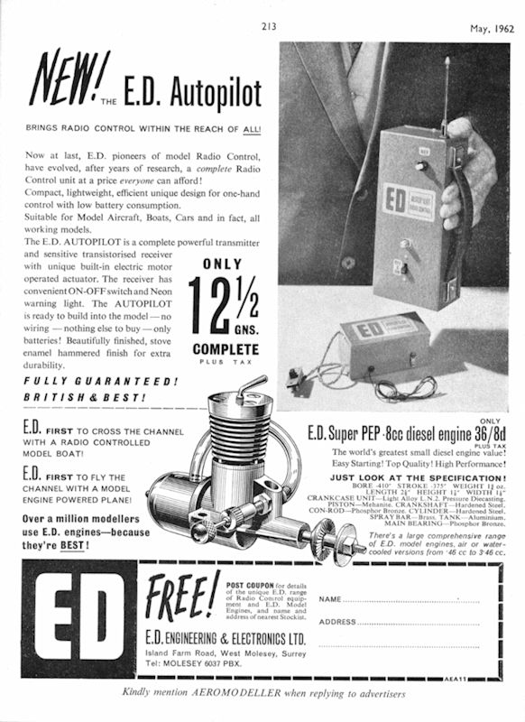 A further sign that change was in the wind was the fact that Fletcher’s arrival in early 1962 coincided with a change in the company’s name from Electronic Developments (Surrey) Ltd. to the somewhat more descriptive name E.D. Engineering & Electronics Ltd., still at the Island Farm Road address in West Molesey. This company name began to appear in E.D.’s advertising in May 1962, as reproduced at the left. It would appear that a new course was in the process of being set for the venerable old E.D. company!
 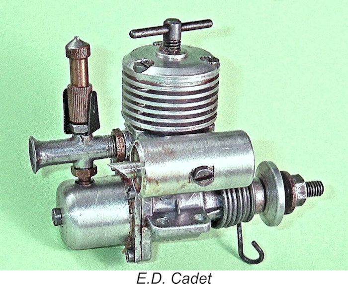 The Baby had already been abandoned, and now the Pep, Hornet, Hunter and Bee were all progressively dropped as parts inventory ran down, with only the Super Fury, the Racer and the very popular 3.46 cc marine-only Sea Otter carrying on as before.
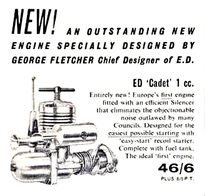
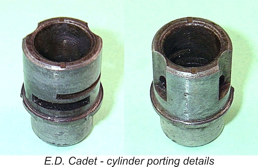 The Cadet's cylinder was completely different from that of the Bee. The integrally-formed cooling fins were gone, being replaced with a separate light alloy cooling jacket. The number of transfer ports was reduced to two 1/8 in. dia. upwardly-angled drilled holes spaced quite widely apart, with bypass being provided by two externally-formed channels as seen in the Bee. Presumably the anticipated lower operating speeds of this sideport sports engine argued against the need for more than two transfer ports.
 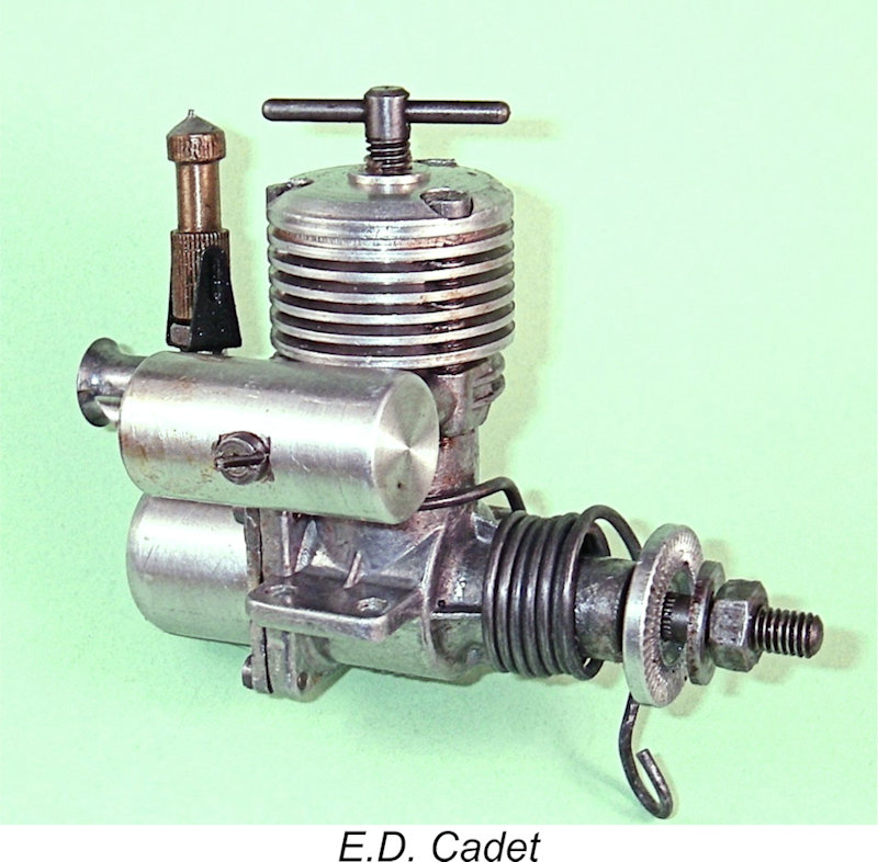 which had first been inflicted upon the British marketplace by
 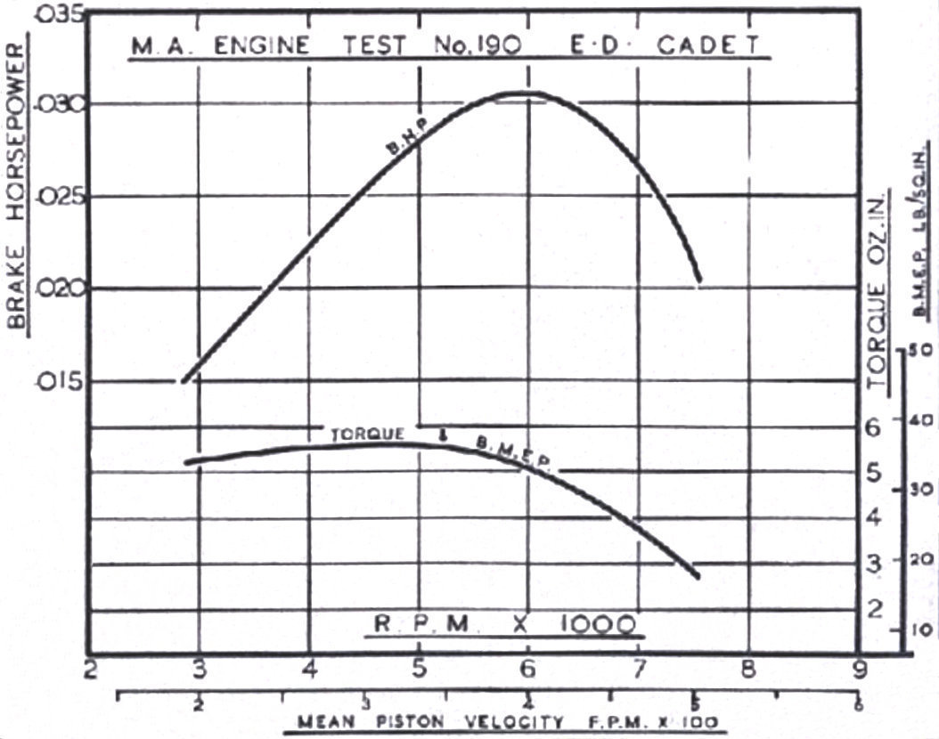 The Cadet was the subject of two published tests. The first of these was conducted by Peter Chinn,
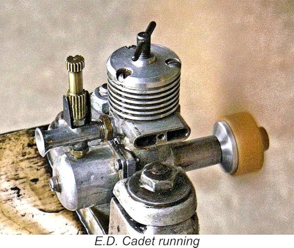
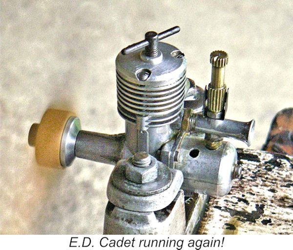 Accordingly, although the engine completely fulfilled its intended role of offering a positive experience for beginners and sport fliers in noise-sensitive urban areas, the reputation for low power that it rapidly acquired sealed its fate in an increasingly unforgiving marketplace. Perhaps because of a combination of the above factors, Cadets are relatively rare and quite highly sought-after today, especially those that actually run! Complete examples which retain both their mufflers and their starter springs are rarer still. Those that do survive constitute a interesting post-script to the story of the E.D. Bee.
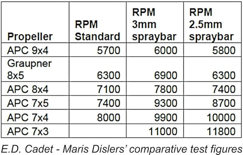
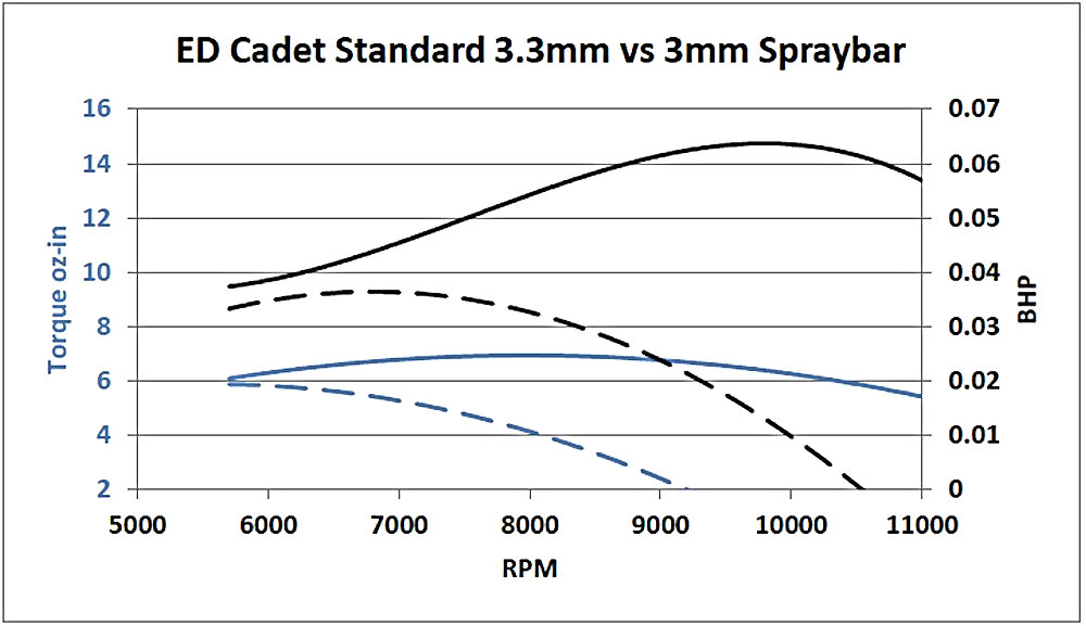
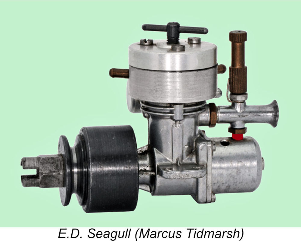
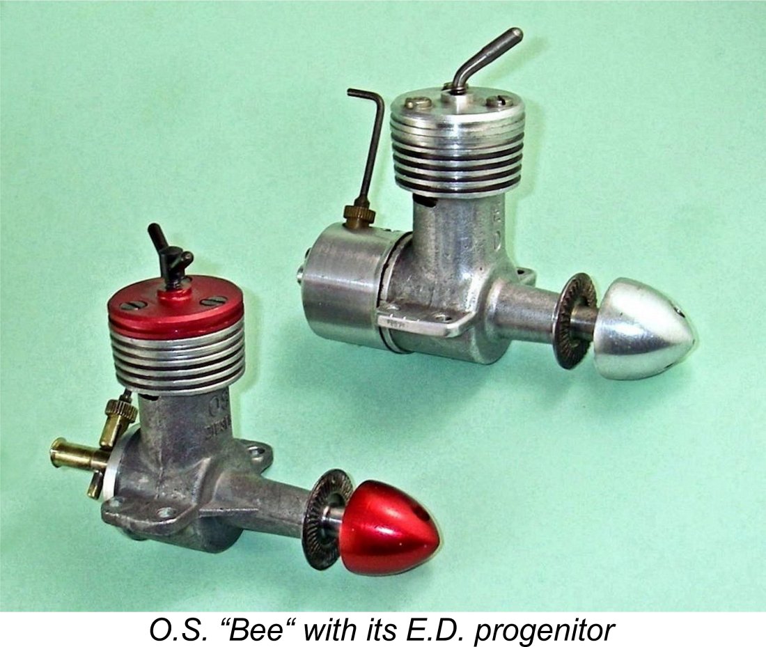 No discussion of the E.D. Bee would be complete without mention being made of the very first diesel to be offered by the famous O.S. company of Osaka, Japan. This is the little-known and very rare
 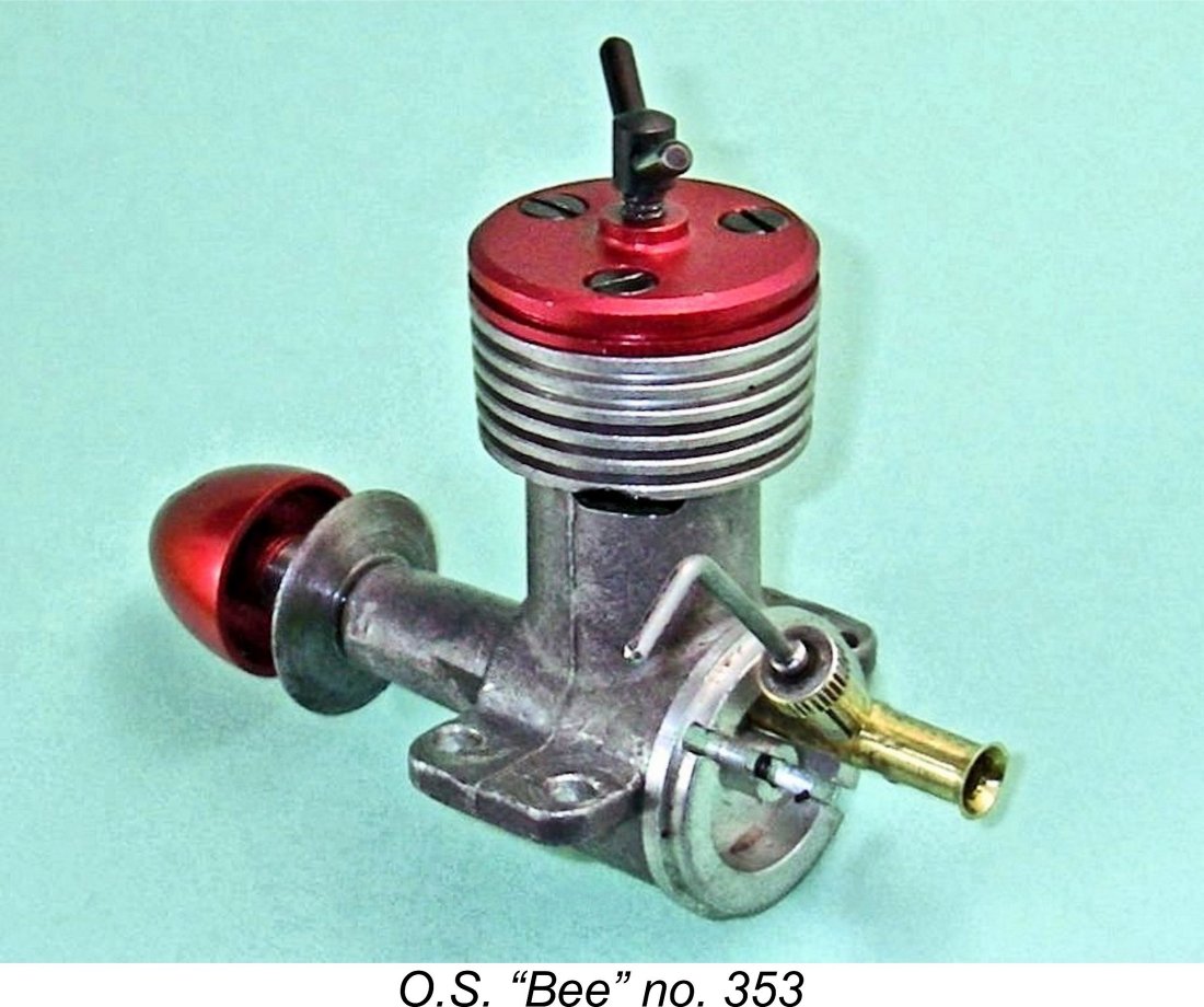 The accompanying images will confirm that the O.S. “Bee” bore a similarity to its E.D namesake which was very far from coincidental. In every significant way, it must be seen as a straight copy of the British product with a few detail modifications. However, there’s absolutely no possibility of mistaking one model for the other. Even across the room, the handsome red anodizing on the O.S. model’s head and spinner are unmistakable, as are the Y-shaped compression screw, the absence of a tank and the consequently exposed bell-mouthed brass intake tube. Viewed up close, the front face of the engine's crankcase proclaims in bold relief that it is an "OS DIESEL".
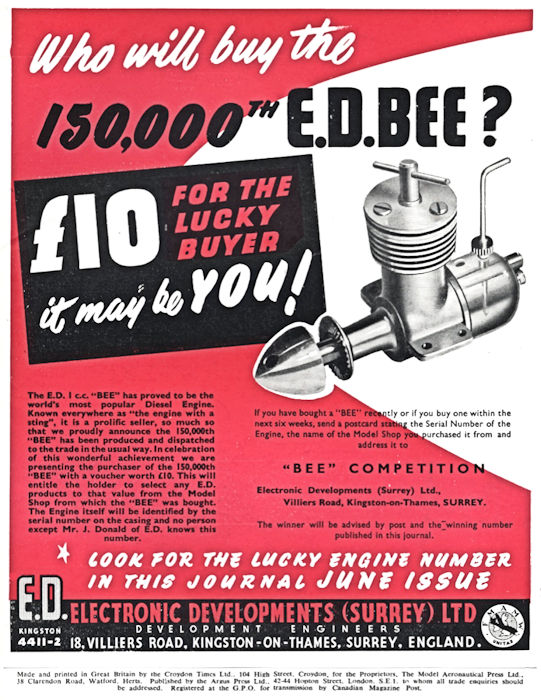 Many people seem to retain some memory of the claim that over 300,000 examples of the E.D. Bee were sold, making it the most popular engine ever to be produced in Britain. The latter statement may well have been true, but how well does the 300,000 claim stand up to scrutiny? Let’s consider the matter …………..
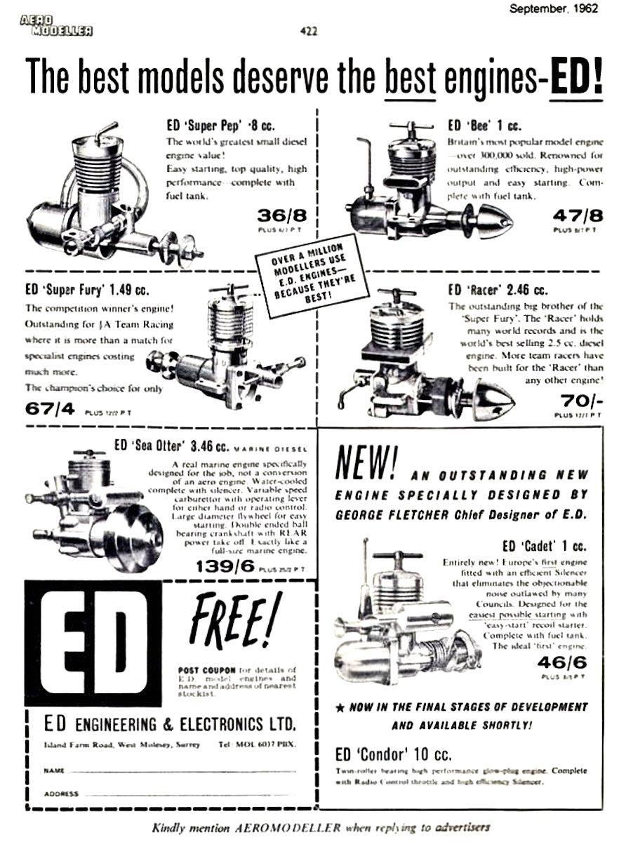
| |