
|
|
The Bungay "High Speed" 600
This article is actually a re-organization and enhancement of an earlier piece which appeared on the late Ron Chernich’s “Model Engine News” (MEN) website in September 2012. I’m re-publishing it here to prevent its loss as Ron’s now-frozen and administratively-inaccessible site steadily deteriorates due to lack of any opportunity to maintain it. The Bungay 600 has considerable significance from a historical standpoint in that it was the last of a series of pioneering crankshaft front rotary valve (FRV) racing motors which challenged the rise to prominence of the "classic" big-bore model racing engine with its disc rear rotary valve (RRV) induction. The telling of the Bungay story thus affords an ideal opportunity to summarize a very interesting technical debate which took place in the context of the early development of model racing engines. As always when discussing an American model engine from the "classic" era, it's necessary right up front to pay tribute to my late and very much-missed friend and colleague Tim Dannels, former Editor of the Engine Collectors' Journal (ECJ). Tim's indispensable American Model Engine Encyclopaedia is a required off-the-shelf reference for anyone having an interest in the products of the American model engine industry. Much of the background material for this article was extracted from that work as well as from back issues of the equally highly-recommended ECJ. Our shared debt to Tim can never be repaid. I'd also like to express my very sincere appreciation of the considerable assistance provided by my valued English friend Miles Patience. Miles is lucky enough to own two original examples of this mega-rare engine. He was most geneous in providing component images which did much to clarify many details of the engine's construction. Thanks, mate! Let's begin now by looking at the background to the development of this very original model engine design. Background
Although tethered hydroplane racing was taking place during this period, its most consistently successful practitioners tended to make their own specialized powerplants. There was thus little stimulation for the commercial development of all-out model racing engines at this stage.
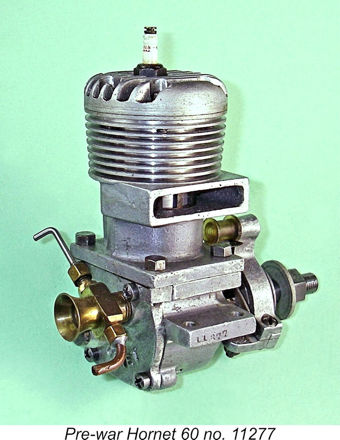
The Dooling brothers were soon joined by others, including the legendary Dick McCoy as well as Ray Snow of Hornet fame. The rapid nationwide increase in the popularity of this new branch of the hobby soon created market conditions in which the commercial development of suitable racing engines became a viable proposition. The resulting powerplants differed quite significantly from their aero predecessors. Weight was far less of an The "formula" established by these front-running early American racing engines was soon to become familiar to performance- However, even at the outset there were those who felt that the above layout could be improved upon. One notable and very influential designer who sincerely believed that FRV induction offered greater potential than the RRV system for racing engines was California resident Ira J. Hassad (1915 - 1981). Hassad's conviction that FRV induction offered a viable alternative to the RRV system for racing engines was to sustain a 10-year struggle for supremacy between the two systems. The Bungay High Speed 600 was destined to be the final FRV participant to enter that contest. This being the case, the need to see our main subject in context requires that we spend some time reviewing this very interesting technical debate of over 80 years ago. Ira Hassad and the FRV 1940's Racing Engine Movement
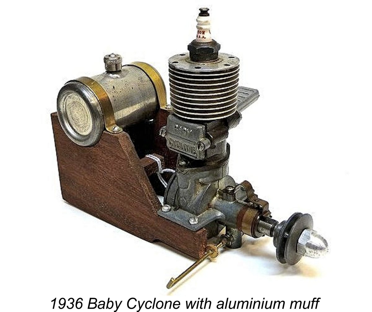
The Baby Cyclone engines were manufactured at a facility owned by Moseley which was dedicated primarily to full-scale aircraft maintenance. This facility was located at Grand Central Terminal in Burbank, California, some 12 miles to the north of downtown Los Angeles. A number of Ira's fellow employees were student pilots paying for their instruction by working for Moseley. Ira was later to recall that his main task was the lapping of the pistons and cylinders to the required fit. Surviving examples of the Baby Cyclone are a testament to his expertise in this area. Some 20,000 of these engines were reportedly manufactured in total. The Baby Cyce exerted a design influence which extended well beyond the USA - Maris Dislers' excellent article on the Baby Cyclone copies may be found elsewhere on this website.
This engine featured the unusual combination (for a racing engine) of a front exhaust with twin stacks, a plain bronze-bushed main bearing, a lapped piston, a five-bolt backplate and FRV induction. It also sported an early rendition of the remote needle valve system later to be employed by Cox, among others. Some 200 examples of this model were reportedly made and sold, a figure which encouraged Ira to continue on his own after Louis Schock found it necessary to return full-time to his regular job at Lockheed. A basically identical model was still in production in 1941, albeit by that time under Hassad's own name.
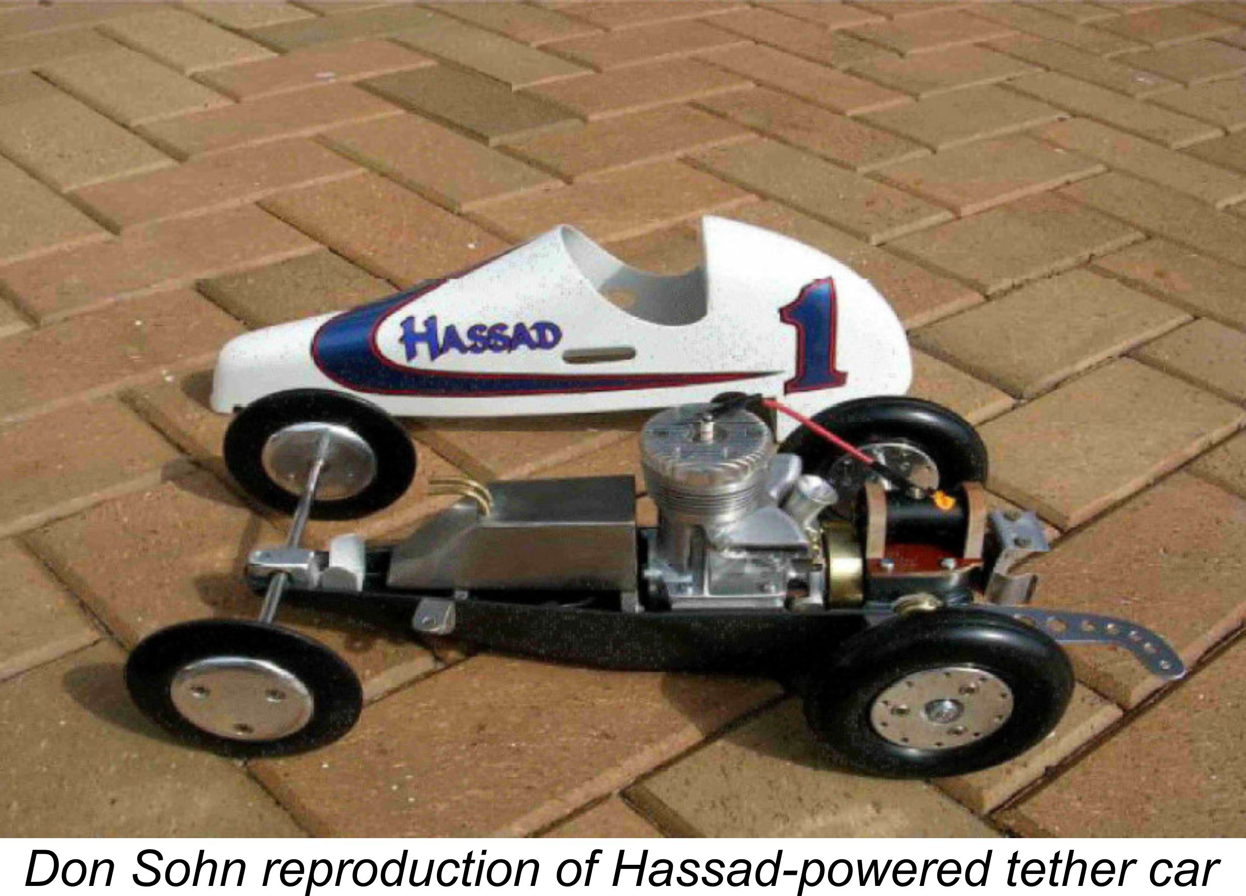
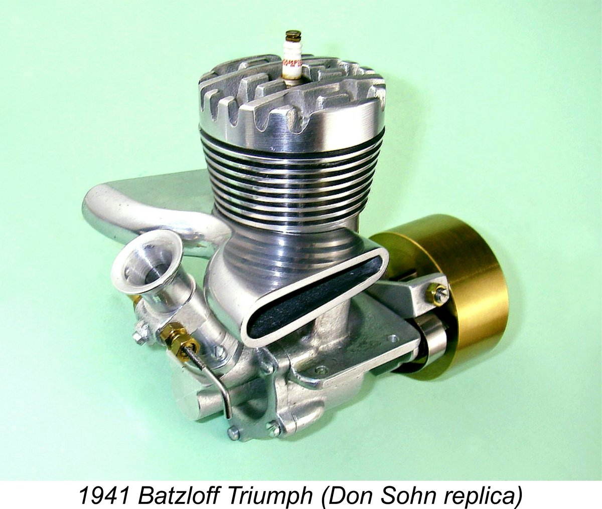
The Triumph was made by Batzloff in very small numbers, production being quickly curtailed by the onset of WW2 (as far as the USA was concerned) in December 1941. Seemingly no more than a dozen complete engines were supplied to custom order, although others were reportedly sold to fellow enthusiasts as casting kits for home construction. The illustrated example was constructed from castings by the noted model car reproducer Don Sohn.
This arrangement allowed the designer to take far greater liberties in terms of induction port size and associated timing without introducing any undue structural weakness. It was presumably this advantage which led Batzloff to adopt the design approach that he did. The engine retained the twin exhaust stacks of the contemporary Hassad models, but these were placed at the rear of the cylinder instead of at the front, thus keeping them in the same orientation relative to the induction system as in the Hassad designs. In effect, the Batzloff Triumph was a "back-to-front" Hassad model - a twin-stack FRV Hassad design with the power take-off at the rear!
During the period just described, Hassad engines dominated the rail-guided model car racing category at meets in Southern California. This was evidently due to their superior torque in the 12,000-13,000 rpm range, which helped them to accelerate out of the turns. Users of these engines included such rail car luminaries as Roy Richter and Clarence Felker in addition to Ira himself and his colleague Bill Batzloff. The accompanying photograph at the right shows Ira at the superb Mission Beach rail track in California standing behind a kneeling row of 10 competitors, all of whom were using his engines. The eleventh car in the photo must be Ira's own entry. However, in tethered cable car racing where the runs were not interrupted by changes in track radius and associated friction, the higher peak horsepower of Ray Snow's RRV Hornet 60 gave it a commanding edge. It was thus a bit of a stand-off between the FRV and RRV induction systems at this stage. The entry of the USA into WW2 in December 1941 put an end to Ira Hassad’s experiments with FRV racing engines, since his engineering talents were required for the war effort. He was relocated to San Diego, California where he spent the war years working for the US Navy as a machinist at their “Sound Lab”, located at Fort Rosecrans Naval Base at Point Loma. He later told his son Jim that he was primarily engaged in making parts for prototype sonar systems, which of course at that time was a top secret technology. However, once the conflict was over he was quick to resume his model engine development activities, continuing to pursue the concept of FRV induction applied to model racing engines.
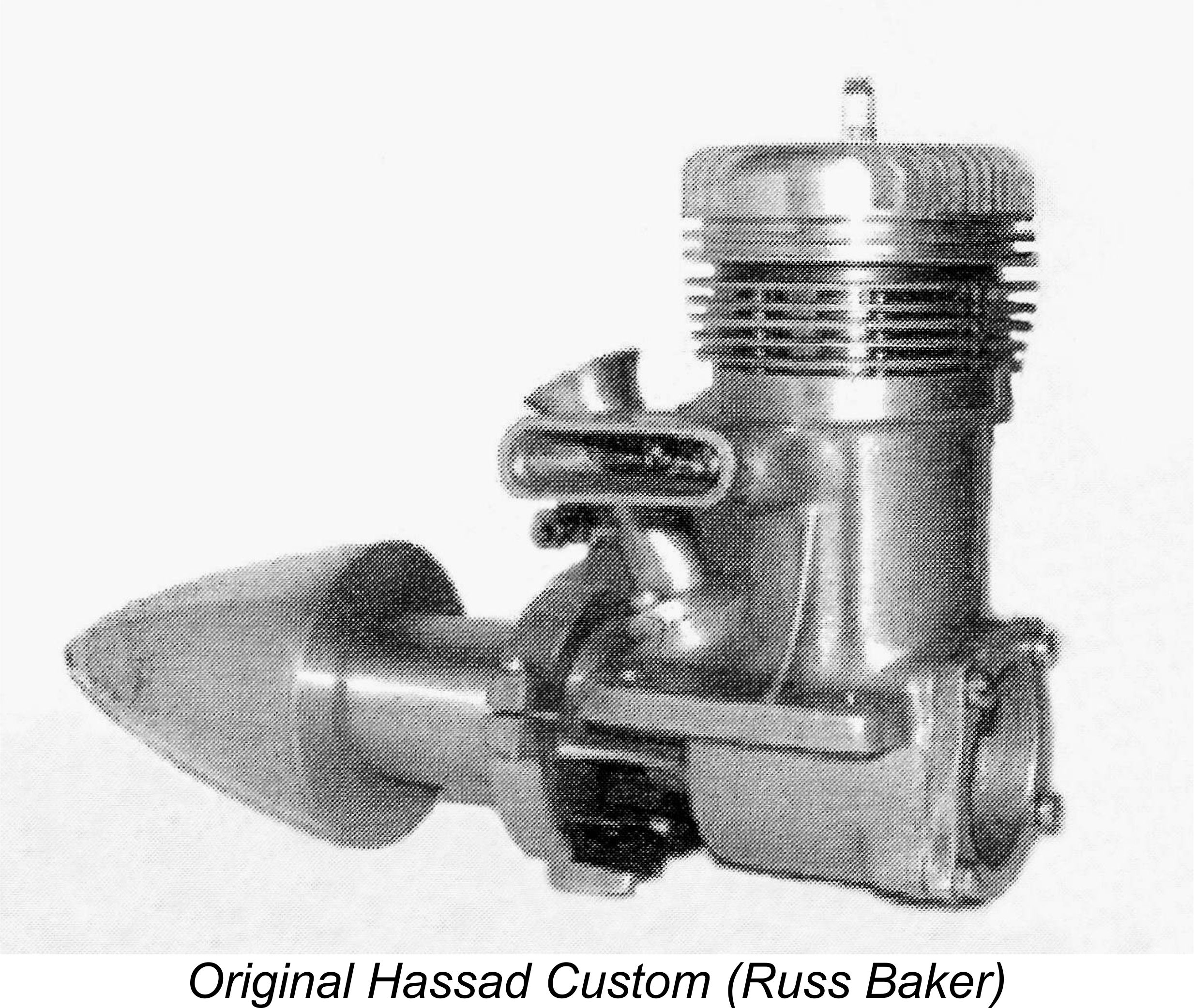
Jim Walker's wartime popularization of the control line system for model aircraft had now made all-out speed contests for model aircraft a practical proposition, since high-speed models could now be flown safely under complete control at all times. Accordingly, Ira's engines were now appearing in aircraft service in addition to the car and hydroplane racing applications in which they had hitherto been employed. The illustrated example of the Hassad Custom .61 is clearly set up for aircraft use. From this point onwards, the model aircraft market became increasingly important to the designers and manufacturers of model racing engines, to the point where it eventually became dominant.
Hassad's involvement with this company during 1947 resulted in perhaps his most recognizable design of them all, the EDCO Sky Devil 1500. This was in effect a somewhat simplified mass-produced version of the Hassad Custom .61. It was another FRV twin-stack front exhaust unit with a twin ball-race shaft and ringed aluminium alloy piston. The engine was offered in both a .649 cuin. aircraft version (the regulations then in force for model aircraft allowed engines of up to .650 cuin.) and a .607 cuin. race car variant which was used in EDCO's own race car offerings.
Original examples of the EDCO engines such as the near-mint example illustrated above are pretty rare these days. The example of the EDCO Sky Devil which is illustrated here at the left is one of some 250 fine .649 cuin. replicas produced in 1983 by Randy Linsalato of RJL (now combined with MECOA). These were made under contract for the late Terry Toupes. Internally, they are not exact replicas, utilizing some readily-available parts from other engines to keep costs under control and lacking the radically-extended prop driver/spinner combination – the components fitted to the illustrated RJL engine are home-made look-alikes. This having been said, in many ways the quality of these RJL replicas equals or even exceeds that of the originals, from which they may be readily distinguished by having the inner surfaces of their exhaust stacks anodized as opposed to the plain milled finish of the originals. They also carry serial numbers having a TDCxxx pattern. These engines run very well indeed and are now fine collectibles in their own right. Randy began work on a second series which was to be closer to the originals, but this project never reached completion due to fading customer interest. My sincere thanks to Randy for personally sharing this information with me. Check out Randy's website – he continues to offer fine products!
As a result of the liquidation process, the bulk of the remaining Sky Devil parts and tooling ended up as the property of EDCO's major creditors, the Tyce brothers, who owned a company called International Tool Corporation of Chula Vista, California, just to the south of San Diego. The established business of this company was the provision of full-sized aircraft engineering services, but they decided to see if anything could be salvaged from the remains of the EDCO venture. To that end, they hired Ira Hassad to come up with a model engine The result was Ira Hassad's last commercial model engine design - the Bluestreak 65, still featuring FRV induction and using many EDCO Sky Devil parts. However, the "classic" formula had made further inroads, since the new design used a revised crankcase casting which featured a conventional side-stack exhaust in place of the twin-stack front exhaust layout used on all previous Hassad designs. Since the engine possessed all of the other classic racing features such as twin ball-race shaft and ringed alloy piston, it followed the now-established racing engine pattern in all respects apart from its continued adherence to FRV induction. Reflecting its time and place, the Bluestreak was offered in both spark ignition and glow-plug versions. It was reportedly a fine engine for free flight and non-racing control line applications. However, in a racing context it could not hold its own with the then-current crop of big-bore racing engines from other manufacturers. Even so, all 2000 or so examples of this engine which were manufactured did eventually find buyers, although it took a while. Long before that happened, Ira Hassad had moved on into other engineering ventures, leaving model engines behind together with his own legend.
The Ball 60 was even more individualistic than the contemporary Hassad designs. Like the Hassad, it featured FRV induction, a twin ball-race shaft and a ringed aluminium piston. However, there the similarities ended. The Ball featured dual exhausts with dual bypasses between them - shades of Cox in years to come! The exhausts exited at both front and rear, with bypass passages on both sides of the case. A similar porting arrangement had been adopted previously by Ira Hassad in his limited-edition disc-valve H.R.E. Special of 1941. That earlier engine may well have influenced the design of the Ball 60. This arrangement allowed the use of six transfer ports (three to a side) along with the six exhaust openings, which were of course split between the two exhaust stacks. The exhaust stacks could be positioned so as to discharge either to the right or left at the owner's discretion. Either way, these twin stacks imparted a highly unusual appearance to the unit.
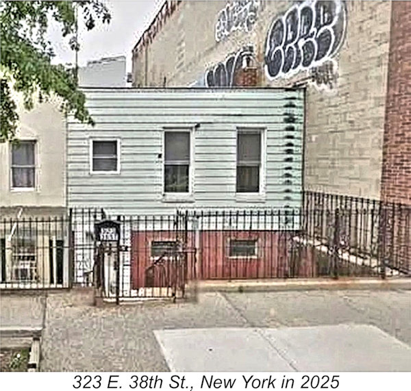
Orr went back to the drawing board, introducing an RRV model called the Orr Tornado 65 later in 1945. This was a basically conventional .647 cuin. RRV racing engine showing a certain Hornet influence along with some original thinking – Orr’s flirtation with FRV induction had not lasted long! The Orr Tornado doesn’t appear to have enjoyed widespread market success, although it was still listed as being available in compendiums of current model engines published in early 1948. Originals in good condition are extremely rare today. I'm aware of one other attempt to create a 10 cc racing engine using FRV induction. This came from the Vancouver, British Columbia workshop of Canadian manufacturer Al Salonen, maker of the Queen Bee range. Probably in 1948, Salonen produced a few prototypes of a superbly-made twin ball-race FRV racing engine. Prototypes of both spark ignition and glow-plug versions of this engine were The upshot of the above experiments with FRV induction was that as of early 1948, only the Bluestreak and Ball 10 cc FRV racing engines remained available to competition modellers who wished to try something different. However, the 1947 introduction of the RRV Dooling 61 had raised the performance ante significantly, to the point where even such leading RRV models as the McCoy 60 and the Hornet 60 suddenly found themselves badly outclassed. This event prompted Dick McCoy to develop his famous Series 20 version of the McCoy 60 which was to outlast the Dooling and remain the world standard for 10 cc racing engines well into the 1960's. Despite the speedy development of a Dooling-influenced bulge bypass performance enhancement kit, the once- Under these circumstances, it may appear in some ways a little surprising that yet another FRV racing engine should appear in 1948. However, it was in that year that the Bungay "High Speed" 600 model (remember that?!?) which is our main subject made its all-too-brief appearance. The manufacturers of the Bungay 600 traded as Bungay Brothers of 323 E. 38th Street in New York City. I've been able to find out absolutely nothing about this company beyond the simple fact of its involvement with the Bungay model engine venture. However, my good mate Marcus Tidmarsh discovered that the building at 323 E. 38th Street from which the company operated is still in existence today (2025)! As of early 2025 this building was up for sale. From the listing, it was possible to confirm that it was built in 1912, proving beyond doubt that it is the very building from which the Bungay Brothers operated. Today it is a two-storey duplex residence, but way back in 1949 it may have been configured quite differently. I suspect that the workshop may have been on the ground floor, with one or both brothers living on the second floor.
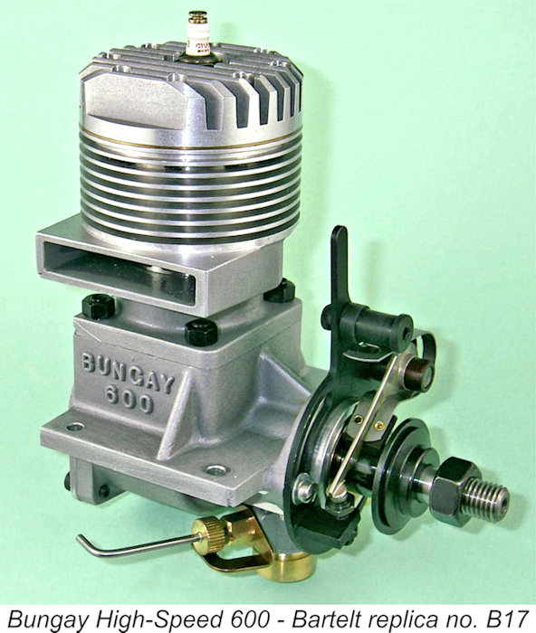
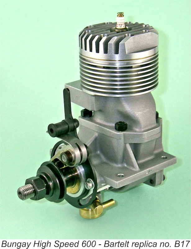
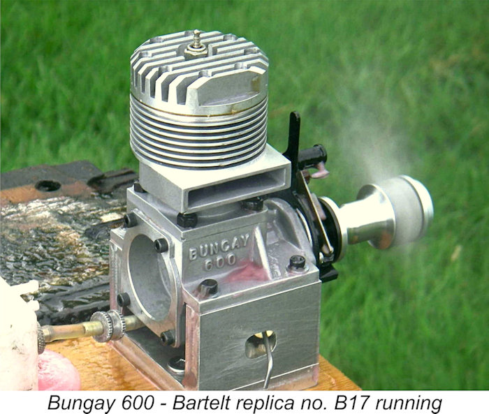
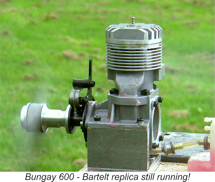
The Bungay 600 is today one of the rarest model racing engines of them all. I've never so much as seen an original in the metal, although my good mate Miles Patience of England owns two original examples. I am only able to undertake this review at all because of my acquisition of one of a series of 100 fine reproductions of this engine which were produced in Ukraine to a very high standard of quality and authenticity for the late Woody Bartelt of Woody's Engines/Aero Electric fame. The engine which appears in the attached images is number B17 of this series. Woody's offering is an almost exact replica of an original example, so I'm satisfied that it may legitimately be used as an object for study of this otherwise "invisible" engine. The Bungay High Speed 600 Described.
In many respects, the Bungay was a typical large racing engine of its time. It featured spark ignition controlled by an automotive-style timer; cross-flow loop scavenging; a sidestack exhaust; a ringed aluminium piston with a high domed baffle crown; and a twin ball-race crankshaft. In fundamental design terms, its only real departure from the established formula was its use of FRV induction. The Bungay featured then-standard bore and stroke measurements of 0.940 in. and 0.875 in. respectively, exactly as featured in the McCoy and Hornet 60 models among others. This gave the engine a displacement of 0.607 cuin. (9.95 cc). Claimed all-up weight minus flywheel, coil and other ignition equipment was 16.25 ounces, although the Bartelt replica in my possession weighs in at 485 gm (17.10 oz.) bare with plug.
As with the Hornet 60, the cylinder liner was carried in a separate casting which in this case was attached to the main crankcase casting by four studs with hex nuts at the corners of the square location flange. The main crankcase casting also followed the Hornet pattern by incorporating the main bearing housing in a single The bypass passage was necessarily formed in part in both the upper and lower castings, again exactly as in the Hornet. The passage used in the Bungay was relatively narrow in a fore and aft sense, but was laterally made far deeper than those used in the Hornet and the 1946-48 blackcase McCoy 60 models. Hence it offered a relatively free passage for mixture to reach the transfer ports despite its comparatively narrow width. The passage was flared significantly at the top to provide unimpeded gas access to all three transfer openings. Although the bypass passage was open at its base in the usual way, a single extra port having an ovoid shape was cut in the cylinder wall below the transfer ports. This corresponded at and near BDC with a similar port in the piston skirt. The result was improved gas access to the bypass passage as well as enhanced piston cooling due to the flow of cool incoming mixture through the piston interior.
The Bungay 600 used a one-piece steel crankshaft having a counterbalanced disc-style crankweb with integral crankpin. The main journal diameter was 0.500 in., again exactly as in the McCoy and Hornet models. So far in fact, apart from the use of steel rings and the method of assembly, we could be talking about almost any big-bore racing engine of the early post-WW2 period.
The next design anomaly with the engine was the fact that the intake was located beneath the main bearing housing rather than in the more usual position on top. This was actually an extremely inconvenient location from a mounting standpoint since the needle had to pass through the right-hand bearer directly beneath the mounting lug. Mounting in a conventional test stand was thus quite impossible. The location also impeded access to the intake for priming or choking when the engine was mounted. It would have been a perfectly straightforward matter to design the engine so as to place the intake in the conventional upper location, implying that the chosen arrangement was the result of a conscious design decision. This of course begs the question of why this arrangement was adopted. My own view is that it was probably motivated by a desire to improve crankshaft integrity at the very high speeds for which this engine was designed. The milling of a rectangular induction port in the shaft undoubtedly created a potential stress-raiser in the middle of the main journal. In particular, the cyclic placement of this feature under high tension loadings would not have been an ideal condition in terms of stresses at this location. The Bartelt replica's induction port has nicely radiused corners and it seems likely that the originals did as well, but even so the feature must retain some tendency towards creating stress concentrations, particularly at the corners of the opening. In a twin ball-race engine, downward pressure on the crankpin imposes a bending force on the crankshaft which places the upper sector of the main journal in tension - not a good situation when a stress-raising aperture is present. By placing the intake below the main bearing, the designer ensured that at the moment of maximum bending stress (Top Dead Centre following ignition), the portion of the journal that was placed in tension was free from any discontinuity - the induction port would still be on the compression side of the journal at this moment and thus less subject to possible fatigue failure at stress concentration points.
The designer solved the problem of creating a rectangular induction port opening in the main bearing in a neat and effective manner. The actual register was milled into the underside of the main bearing housing, taking the form of a rectangular opening with a flat rectangular surface around the edges. The dimensions of the register opening were 0.400 in. wide by 0.562 in. long. The axial length of the crankshaft induction port was cut to match the latter dimension. Apart from providing an unusually generous register area, this arrangement also promoted extremely rapid opening and closing of the induction system along with an The tubular venturi was carried in a separate casting which was attached to the register opening using two machine screws with a gasket to seal. The venturi itself was of brass, with a generous internal diameter of 0.375 in. A surface jet needle valve assembly was employed, the installation of which served to retain the venturi within the casting. The externally-threaded needle was very effectively tensioned by a spring clip of bronze sheet which bore against an externally serrated disc. Somewhat uniquely, the braced mounting lugs extended on both sides for almost the full length of the engine. While this permitted an unusually secure mounting, it was more than a little awkward for mounting in a model aircraft or a test stand. The full 2.55 in. lateral width of the lugs was carried through to the front of the engine, only some 0.875 in. behind the front face of the prop driver. The use of this engine in a speed model aircraft pan (the unit's obvious model aircraft application in view of its performance characteristics) would have required both the trimming of the lugs at the front and the use of some kind of bobbin-type prop driver extension with a sleeve nut for prop attachment.
The timer design was quite original. The components were mounted on a stamped steel frame which was a close fit over the outside diameter of the front ball race housing. This housing incorporated an expanded section at the rear which formed a flange against which the timer frame abutted. The unit was secured against this flange by two screws with washers. These screws passed through annular slots in the frame to engage with tapped holes in the front of the mounting lugs. The slots permitted the timer to be rotated through 90 degrees using the integrally-formed timer arm. The ability to vary the tension on the screws allowed easy adjustment of the unit's resistance to rotation. Overall, the arrangement provided very secure fixing of the engine's timing while permitting easy adjustment during operation if necessary. Once a satisfactory running setting was established, the screws could be tightened down firmly to preserve the adjustment. The fixed point was attached to a lug which was brazed onto the timer frame at the front. A conventional automotive-style moving point was employed. The cam was machined at the rear of the steel prop driver, which was secured to the shaft using a Woodruff key. Interestingly enough, the prop driver had no serrations of any kind on its driving face to resist prop slippage. It did however feature a hole drilled through it at one point, presumably to accommodate a plug key inserted into the prop or flywheel hub. With an engine of this torque potential, such a provision would have been very necessary. A conventional prop nut and washer were used to secure the airscrew. According to the company's literature, the flywheel-equipped race car version of the Bungay 600 possessed a feature called automatic timer advance. This was presumably some kind of spring-actuated delayed-action system which advanced the timing automatically from the retarded starting setting to the best running setting over a short period of time after starting. This would have been a great advantage for push-starting a model race car. Since I don't currently have an example of this fitting to examine, I can provide no details of the mechanism.
The Bungay designer solved this problem very neatly by installing a steel disc on the front face of the backplate. This both minimized rearward movement of the rod and presented a steel restraining surface, thus creating an alloy-on-steel working combination which was far longer-wearing and less likely to create metallic particulates. The plate had a central spigot which passed through a hole in the centre of the backplate and was secured by swaging from the outside once installed. Overall, one gets the impression that some well-focused design thinking went into this engine. The castings too are unusually complex, indicating either that the manufacturers were experienced producers of high-quality castings or that they had ready access to such expertise. Although the commercial glow-plug had well and truly arrived by mid-1948 when the Bungay first appeared, the engine was specifically designed for spark ignition operation. In fact, the manufacturer's instruction sheet stated that the use of glow-plug ignition would reduce power output by some 30%. Given the rapid rate at which the glow-plug displaced spark ignition from this time onwards, we might doubt this statement for an engine that was properly set up, fuelled and loaded - other contemporary Recommended fuel was a straight mixture of methanol and AA castor oil. The original typed instructions specified an 80/20 mix of these two components, but the copy reproduced here has had these figures altered by hand to 75/25 - whether by the manufacturers or by an owner is unclear. Perhaps experience showed that the higher oil content was an aid to longer life and greater reliability at the very high speeds at which this engine was intended to operate. The instruction sheet specifically warned against the use of gasoline in this unit. The instructions also claimed that each engine was fully run-in at the factory and was therefore ready to run fast as supplied. If this was indeed the case, the Bungay Brothers must have enjoyed a certain notoriety among their New York neighbours when it came to ongoing noise levels emanating from their operation! The Bungay High Speed 600 - Design Considerations
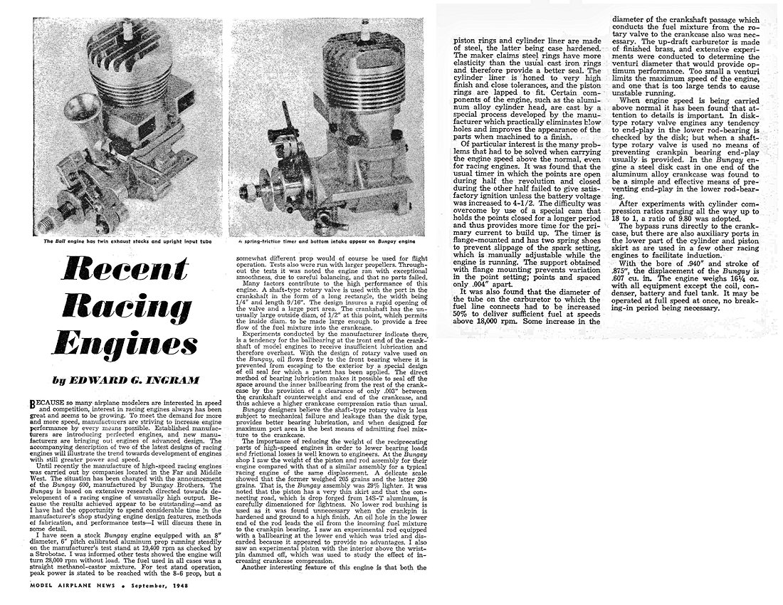
This comes about because the early post-war model engine commentator for "Model Airplane News", Edward G. Ingram, took a close interest in the Bungay 600, going so far as to spend some time in New York with the manufacturers discussing the design and observing actual tests of the engine. Ingram's detailed comments were published in the September 1948 issue of the magazine, along with similar comments on the Ball .604 unit which remained available at the time. Ingram was clearly sufficiently impressed with the design originality and observed performance of the Bungay to prompt him to delve quite deeply into the details of the design. Fortunately for us, he asked a number of the very questions that we would ask the designers today given the opportunity. The first question was of course the reason for the manufacturer's choice of FRV induction at a time when the RRV Dooling 61 and its ever-improving McCoy opposition were sweeping all before them. Ingram obtained a very direct answer from the designers to this question. He recorded their belief that "the shaft-type rotary valve is less subject to mechanical failure and leakage than the disk type, provides better bearing lubrication, and when designed for maximum port area is the best means of admitting fuel mixture to the crankcase". A valid additional point that could have been made (but wasn't) was the fact that the use of FRV induction eliminated the friction and viscous drag of the rear rotary disc which were inescapable elements of the classic RRV layout. The manufacturers put their money where their mouth was on the lubrication issue, machining the shaft to very close dimensions to leave a specified clearance of only 0.003 in. between the rear edge of the outer rear ball race and the front face of the crankweb. The stated idea here was to effectively eliminate the volume of the bearing forward of the crankweb from the working volume of the crankcase, thus promoting better operating crankcase compression and improved transfer. Primary reliance was placed upon oil supplied from the induction system to lubricate the ball races. The front race was shielded at its forward end by a thin bronze disc which rotated with the prop driver, a system which was apparently patented by the designers.
To put this in perspective, the piston/rod assembly from a McCoy 60 weighs a checked 18.4 gm complete with rings and gudgeon pin. It's thus likely that this (or perhaps the very similar Hornet assembly) was the standard against which the Bungay was checked in Ingram's presence. The unusually low weight of the Bungay assembly would certainly have improved both performance and mechanical reliability. A commendable and worthwhile achievement by the Bungay designers! Ingram questioned the rationale for the use of steel piston rings. In response, the makers claimed that "steel rings have more elasticity than the usual cast iron rings and therefore provide a better seal". Ingram also commented upon the castings used in the engine, stating that they were produced by a special process developed by the manufacturers. This was claimed to practically eliminate blow-holes and yield a superior finish when machined. No further details were provided, although this sounds to me like a form of pressure die-casting. The manufacturers mentioned a specific problem which they had had to overcome during the design of the unit. This was the fact that at the very high speeds for which this engine was designed (in accordance with its name!), timer operation was so rapid that with normal operational parameters there was insufficient time for the primary current in the ignition circuit to build up to satisfactory levels unless the applied battery voltage was increased to 4½ volts or more. The solution adopted was to design the cam so as to increase the proportion of time during which the points were closed prior to the initiation of the actual spark through the opening of the points – generally referred to as the timer’s dwell period. A further concession to high speeds was the recommended use of a point gap of only 0.004 in. to minimize point float. Using this set-up, the engine could reportedly be operated on a 3 volt supply. The downside would have been that a long dwell period greatly decreases battery life, also placing the coil under greater thermal stress. Ingram was also able to report on a number of experiments which had been undertaken by the designers during the course of the Bungay's development. A range of compression ratios all the way up to 18 to 1 (!@#?! Diesel fuel, anyone?!?) had apparently been tried, with the final ratio of 9.8 to 1 being selected only after the completion of these experiments. There had also been experiments with piston design, including one in which the piston interior above the gudgeon pin was completely solid, the idea being to further reduce crankcase volume at the expense of increased reciprocating mass. A conrod with a ball-race big-end bearing was also tried, presumably influenced by the Dooling 61's successful use of a needle roller big-end bearing. The results achieved did not justify the application of these ideas to the production version of the engine, although Ingram was shown the experimental parts used in these tests.
Ingram reported seeing a Bungay 600 turning an 8x6 airscrew at 19,400 rpm on the bench using straight methanol/castor oil fuel. If that prop had been a present-day APC, it would have taken an output of around 1.1 BHP to achieve that figure based on established power absorption coefficients. Not having details of the prop involved, all that we can say is that the performance observed by Ingram seems entirely consistent with the manufacturer's performance claims. Ingram reported that no mechanical failures were observed during the course of the tests which he witnessed. A parameter which was widely touted by model engine manufacturers at the time, particularly those involved in the production of car racing engines, was the engine's free speed capability when running without load. Although this is completely irrelevant in terms of the engine's performance under load, it was frequently quoted by manufacturers, presumably in an effort to impress the customers. The Bungay advertising claimed a free speed of 27,000 rpm, although the claim made to Ingram during his visit to the factory and repeated in the instruction sheet was increased to 28,000 rpm. Apart from leaving us impressed that the engine could withstand such abuse, the fact that this was 10,000 rpm beyond the unit's claimed peak renders the figure of little practical value. One supposes that it might have had "insurance" value to car and hydroplane users given the fact that engines used in those disciplines had to withstand very high speeds when the unit was unloaded either during the start-up procedure or as a result of airborne "excursions" during operation! Overall, Ingram was clearly very impressed with the Bungay, summarizing it as the result of "extensive research directed towards development of a racing engine of unusually high output" and characterizing the results achieved as "outstanding". Quite a testimonial! He later featured the Bungay as one of the 10 cc racing engines discussed in his very instructive article entitled "Hot Engine Design" which appeared in the November 1949 issue of "Model Airplane News", despite the fact that the engine was then long out of production. The Replica Bungay 600 On Test
To begin with, I made up a simple mounting cradle out of 3/8 in. aluminium alloy plate. There are some commercial firewall mounting units with adjustable bearer spacing available for engines in this displacement category, and I have no doubt that one of them could also be made to work, especially if mounting in a model aircraft was on the agenda. I was unwilling to even consider trying the engine without some kind of positive measures to prevent prop slippage given the plain un-knurled driver. To deal with this issue, I made a bobbin prop driver extension having a knurled front face and an offset blind recess at the rear which matched the location of the existing hole in the standard steel prop driver. A steel mushroom stud was made to fit in this recess and engage with the hole in the standard prop driver. I have little doubt that anyone planning to use this engine in a speed model aircraft would have made similar arrangements. I used a "shim" of gasket material between the steel driver and the rear of the bobbin to minimize any marking-up of the steel prop driver face.
Choking or intake-priming the unit was of course impossible - all that I could do was open the needle valve all the way, ensure that the fuel line was full and then administer a healthy port prime. However, this did the trick nicely - so nicely in fact that the engine quite literally started on the very first flick! A good beginning ...........and it didn't stop there. Once running, the needle could be closed down a bit to give a nice even break-in rich-lean setting. The engine proved to be a superb runner, needling very well and running extremely smoothly with no signs of distress at any time. Noise levels were pretty spectacular, and the level in the fuel tank dropped like a bath-tub with the plug pulled on the slightly rich setting that I used in deference to the engine's new and unused state.
At this point in its operating life, the engine felt truly superb - compression seal was up to diesel standards and there were no signs of any developing play in the rod or shaft assemblies. Since I didn't plan to actually use this engine in a model, I saw little point in completing the break-in procedure at this time. Suffice it to say that the replica Bungay proved to be a delight to handle and undoubtedly displayed the performance to give a very good account of itself against the majority of the 1948 opposition. Production History
The price of the engine was $37.50 post-paid within the USA. This was relatively steep by then-current standards - the Hornet and McCoy 60's both sold for $35.00 at the time, as did the Dooling 61, while the McCoy 60 Series 20 which appeared later in 1948 carried a reduced dealer price of only $27.50. It seems not unlikely that the manufacturers had decided to hedge their bets by making a relatively small initial production run of the engines and testing the market by offering them direct to customers. Both aero and car versions are known to have been offered, but neither model appears to have attracted much market attention despite the continuing appearance of media advertisements for some time after mid-1948. This was likely due to a combination of price and the Bungay's failure to match the performance of the new breed of RRV racing engines which had been introduced by the Dooling 61 and was continued with the McCoy 60 Series 20. The awkwardness of the design from a mounting standpoint as well as its marginal adaptability to aircraft use may also have played a part in this outcome. Few if any model shops appear to have stocked the engine - essentially all sales were factory-direct.
The next contemporary mention of the Bungay 600 that I've been able to find appeared in another article by Edward G Ingram which was published in the June 1949 issue of "Model Airplane News" under the title "Present Day Motors". The Bungay engine was covered in a single paragraph (left) in this article. This paragraph may actually have been written some time previously. It seems that the manufacturers had continued their development program, since Ingram reported that they hadfound an extra 1000 RPM on a given load through an increase in the transfer port area of some 50%. If this is applicable to the engine's performance in the 18,000 RPM range, it implies an increase in power output of some 17% - a very worthwhile gain, albeit insufficient to bring the engine up to Dooling and McCoy performance levels.
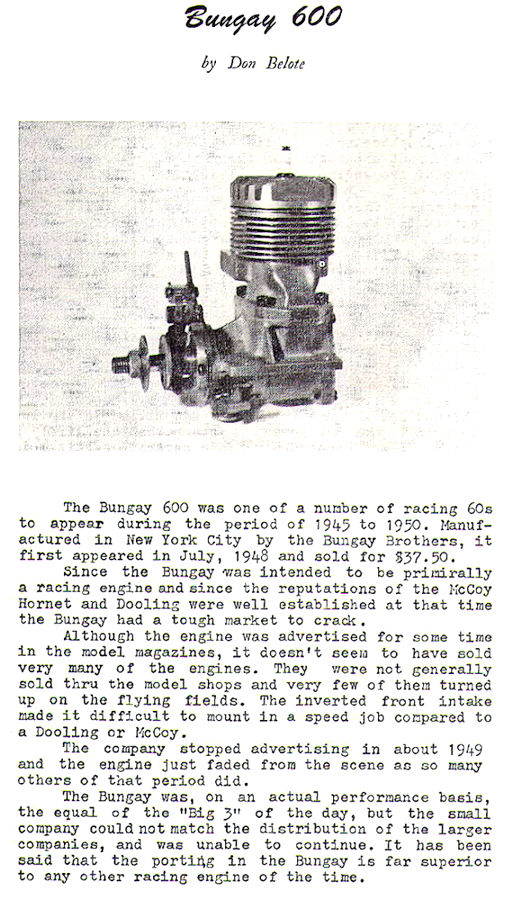
The balance of the paragraph was devoted to an operational description of the auto-advance timer to which reference was made earlier. The implication was that this timer was a later development which followed the initial release of the engine. It seems that the engine was started with the timer in the fully retarded position, after which it automatically advanced itself to a pre-set running position. The operational advantages of this are obvious. Unfortunately, Ingram did not provide any details of the mechanical design of the timer, leaving us still in the dark on that point. As mentioned earlier, the Bungay made a final media appearance as one of the 10 cc racing engines discussed in his very instructive article entitled "Hot Engine Design" which appeared in the November 1949 issue of "Model Airplane News", despite the fact that the engine was then long out of production. This was the Bungay’s final appearance in the modelling media until it made a brief appearance in the January/February 1965 issue of ECJ, some 16 years after it had disappeared from the scene. This reference took the form of a short article by the late Don Belote, as reproduced above at the right. The engine returned to the pages of the modelling media in April 1981, when it was featured in retrospect as the "Engine of the Month" in John Pond's "Plug Sparks" vintage model column in "R/C Model Builder" magazine. This added little to our knowledge of the engine, but it did provide a useful summary, including Allen Pond's excellent 3-view drawing. Thereafter, no more was heard of the engine until the appearance of the present article in its original form on MEN in September 2012. Conclusion
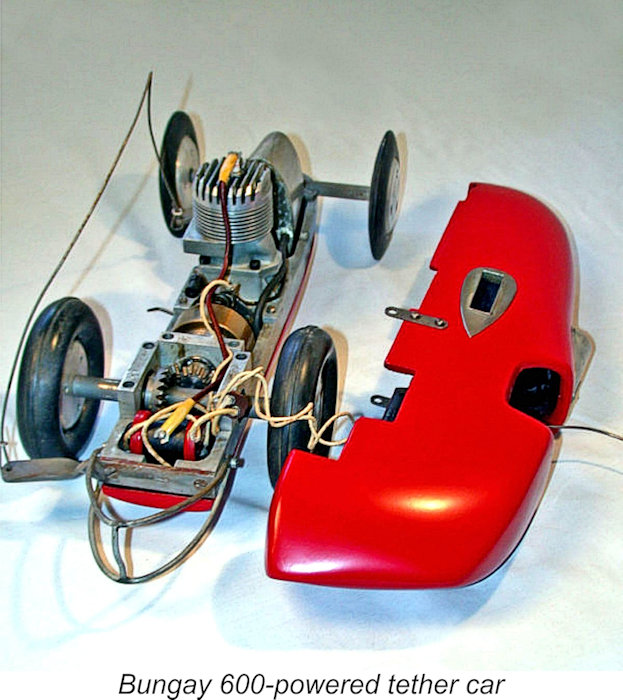
Consequently, the engine stood virtually no chance of being adopted by the leading competitors of the day, whose successes provided the main publicity for the engines that they used. John's overall comment was that "with no National records to claim, no big contest wins and no outstanding big name in speed utilizing the engine, it was a foregone conclusion that the engine simply could not succeed, no matter how good it was". The consequence of the engine's failure to excite the contemporary marketplace is that the Bungay 600 is one of the rarest racing engines of them all today. Originals do exist, but in very small numbers - finding one nowadays is rather akin to finding Long John Silver's original wooden leg, and you'd better have your credit card well warmed up! Miles Patience got really lucky! A nice example of a custom-built tether car powered by an original Bungay 600 was offered on eBay in 2010 for no less than $8,000! I didn't bite ................... There's undoubtedly a far better chance of acquiring one of Woody Bartelt's fine reproductions than an original. These beautifully-made replicas are quality collectibles in their own right as well as being excellent units for actual use if that's what's desired. Overall, an intriguing and refreshingly individualistic design which proved to constitute the final rearguard action for the proponents of FRV induction in large racing engines as opposed to the all-conquering RRV models, at least at the time in question. History shows that the RRV designs swept the FRV units aside and remained dominant until the early 1960's, when new developments in scavenging technology brought about a resurgence of the FRV racing engine, initially in the smaller displacements. What goes around, comes around................ Regardless, I hope that you've enjoyed this look at an interesting piece of model engine history. Hats off to the Bungay Brothers for a very sincere effort to carry the FRV torch forward by putting their very original ideas on model engine design into actual practise! _________________________ Article © Adrian C. Duncan, Coquitlam, British Columbia, Canada First published on MEN September 2012 This revised edition published here January 2026
|
 In this article I’ll take a look at the Bungay "High Speed" 600, an almost-forgotten early post-WW2 American model racing engine which was among those which unsuccessfully challenged the "classic" racing engine formula established by the
 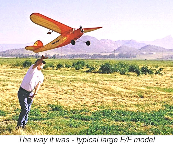 Prior to 1937, the majority of model engines were used to power large free flight model aircraft such as that seen taking flight at the right. Since these models were uncontrolled following launch, attempts to achieve high speeds would have been potentially hazardous, to say nothing of the difficulty of obtaining accurate speed measurements. Contests were therefore based upon flight duration for a given motor run, thus making light weight and operational consistency the primary goals of engine designers. For a taste of how things used to be, check
 Ira James Hassad
 The twin-stack front exhaust was to remain a Hassad trade-mark for most of the following decade. There is much to commend the layout when the engine is used in aircraft service, since it places the hottest side of the cylinder at the front where it receives maximum cooling airflow, thus contributing to more uniform cylinder temperatures. However, any advantage which this layout may possess in terms of operating temperature distribution is often negated when the engine is used in car service, since in a typical bevel-geared car featuring rear wheel drive (like that illustrated here) the exhaust would then face the rear of the vehicle. The same would apply to the engine's use in tethered hydroplane service.
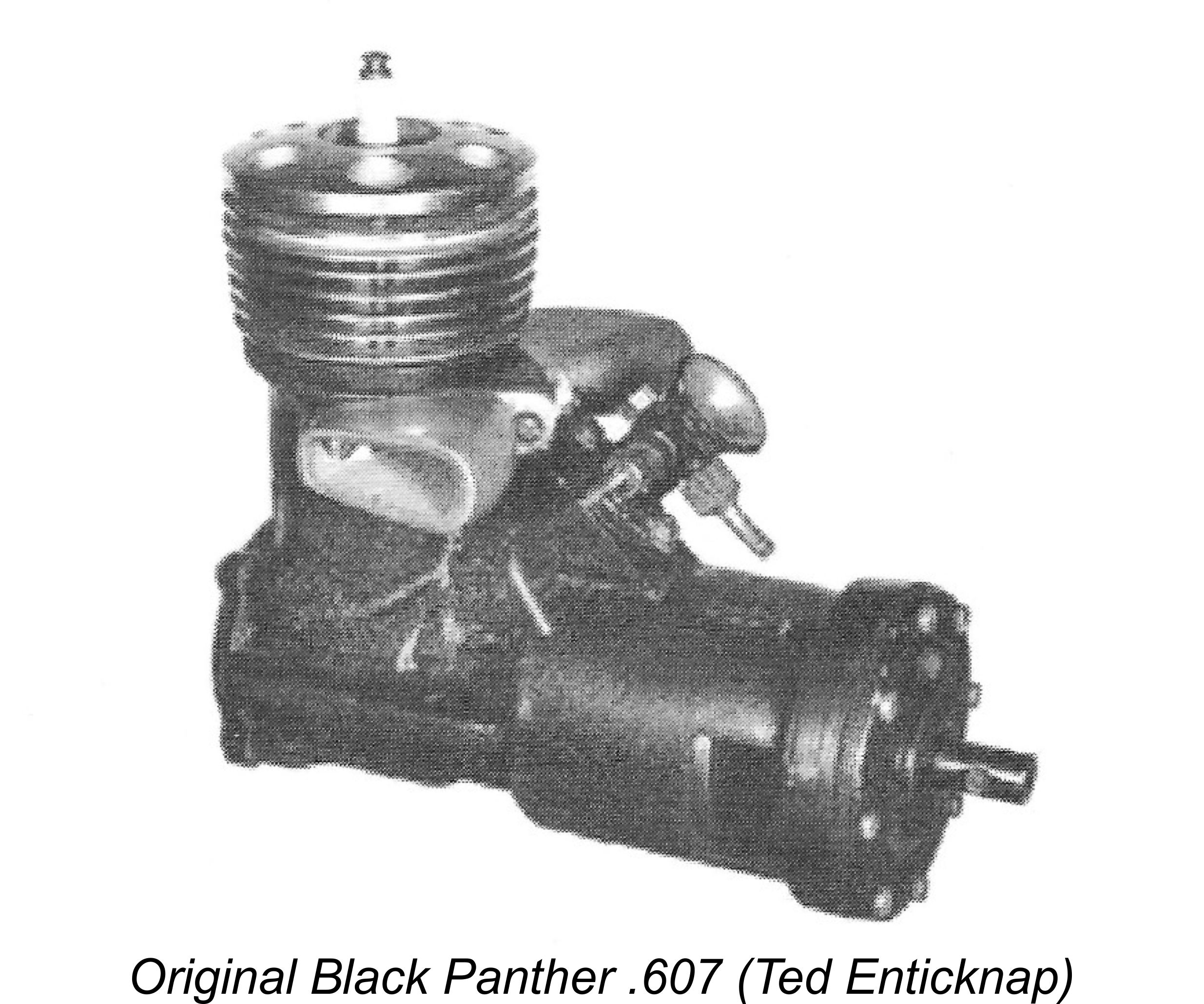 The Hassad engines were very successful in competition, a fact which did not go unnoticed by other California-based model engine designers. In 1941, Los Angeles resident Johnny Lockridge produced a very few examples of the Black Panther .607 car engine. While the Black Panther certainly incorporating a good deal of Lockridge's own thinking, it displayed a very definite Hassad influence, featuring FRV induction to go along with a twin-stack front exhaust system. The flywheel and timer of this ultra-rare model were neatly enclosed in a forward extension of the main crankcase. Production of this engine was apparently suspended rather abruptly after a well-heeled friend of Ira Hassad's called on Lockridge and threatened him with legal action over what he saw as an unauthorized Hassad "rip-off"!
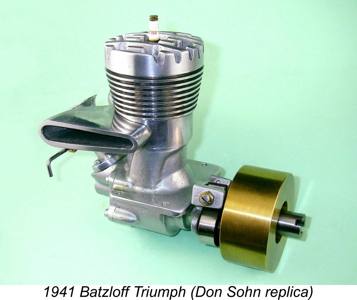
 The Triumph clearly embodied Batzloff's views regarding how the basic Hassad design could be improved upon. The crankshaft was equipped with a single ball-race at the rear in place of the Hassad's plain bronze-bushed bearing. In addition, the engine reversed the usual Hassad arrangement by using a rear drum valve instead of FRV induction. The operating principle was of course identical, the difference being that the drum valve did not have to do double duty by transmitting the engine's torque in addition to controlling the induction cycle.
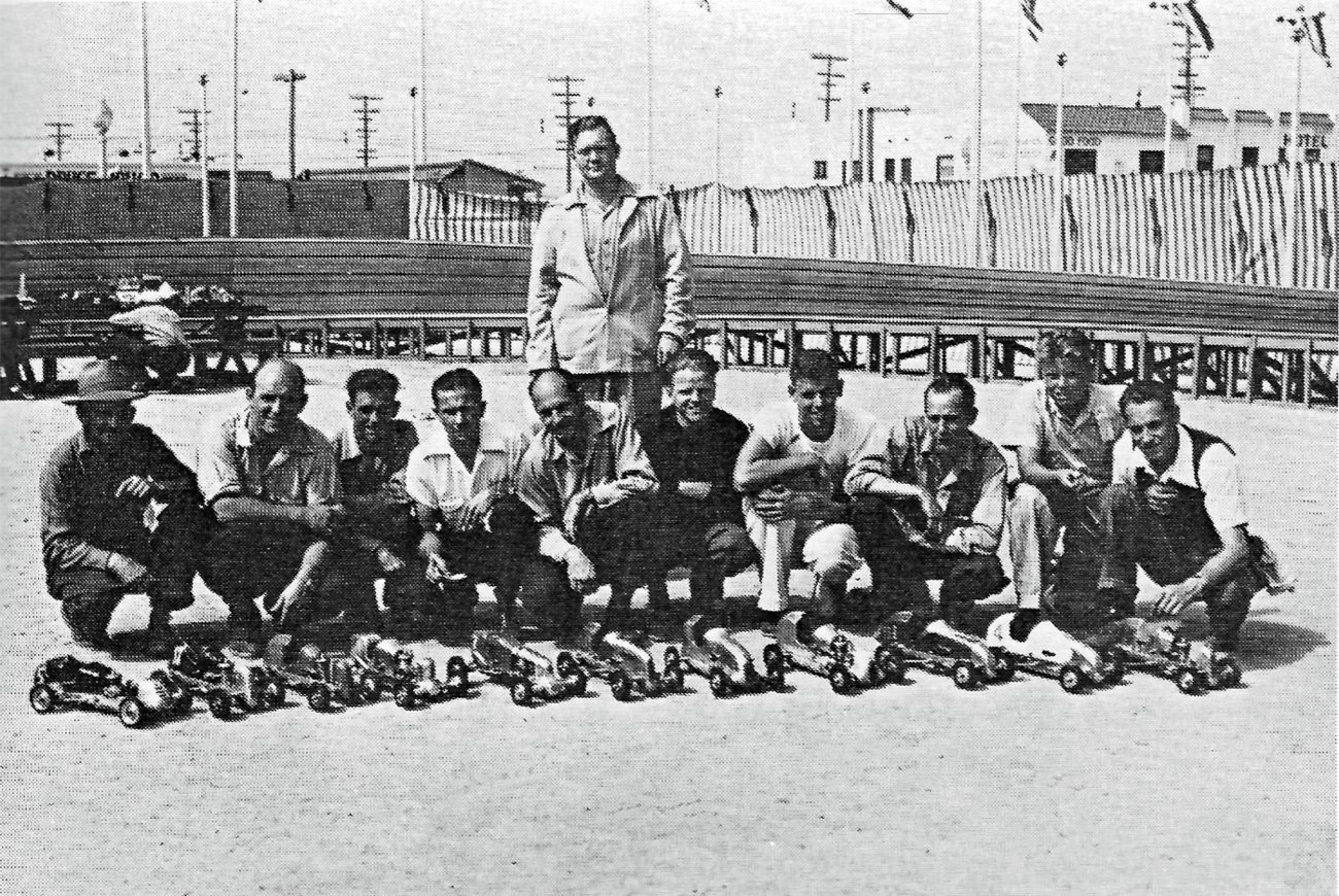
 By 1946, Ira had established himself in San Diego under the company name of Hassad Experimental Machinists. Here he produced around 125 or so examples of the individually hand-crafted Hassad Custom .61, a true masterpiece once again featuring FRV induction and a twin-stack front exhaust. However, the "standard" formula was beginning to make inroads into Hassad's thinking – a twin ball-race shaft was now incorporated, while some examples of the new model featured a ringed aluminium alloy piston. Even so, the continued use of FRV induction and the front exhaust set the design well apart from other leading racing engines of the period.
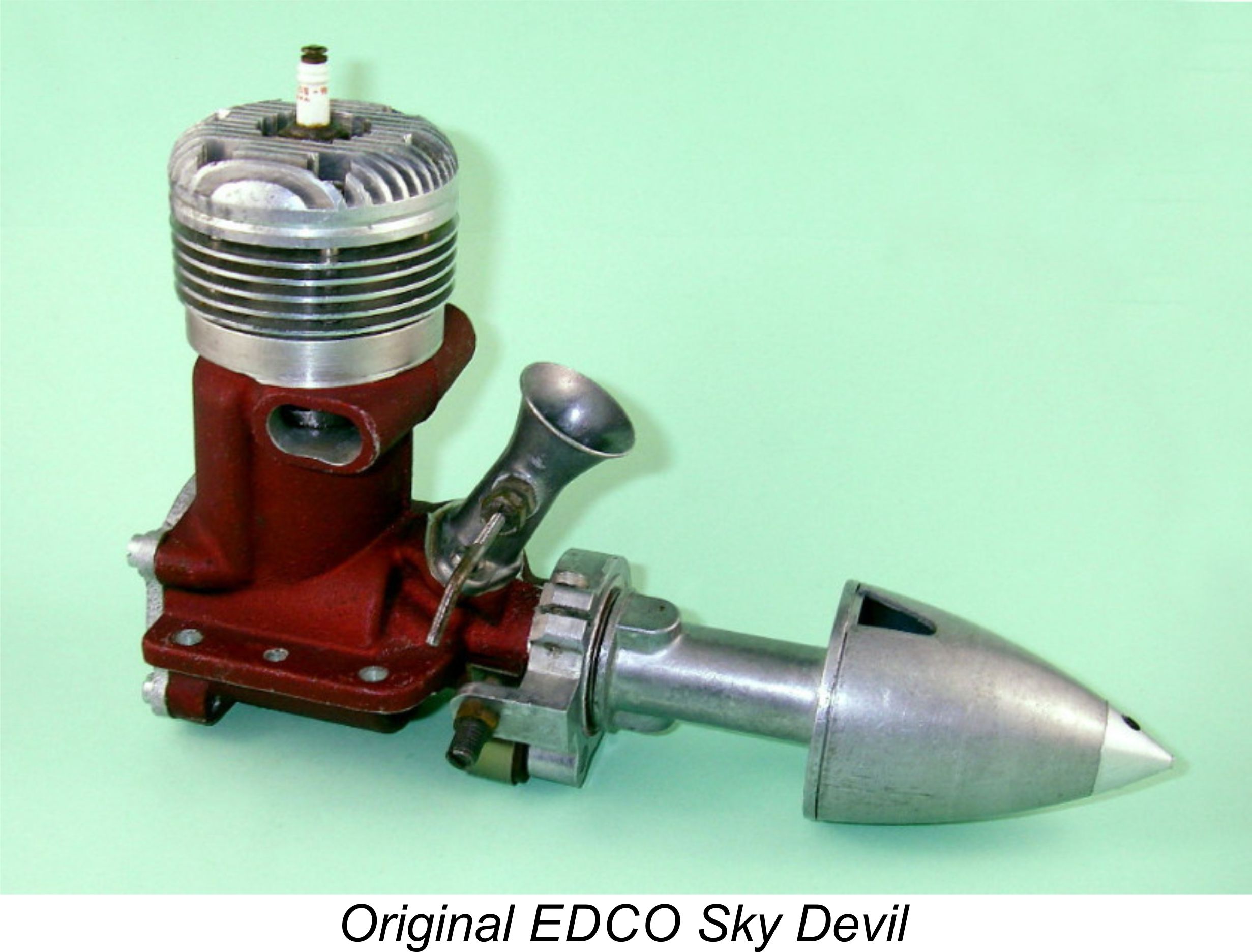 The Hassad Custom .61 proved to be a formidable competitor, a fact which did not go un-noticed by others. A certain Mr. Frank Howarth, owner of a company called Engineering Development Co. Inc. (EDCO), decided that a mass-produced version of this engine would enjoy good sales prospects, accordingly inviting Ira Hassad to come to work for him on the engine side. The company was established in premises located at Del Mar Airport in the oceanside community of Del Mar, a little to the north of San Diego, California, where Hassad had been living since the beginning of WW2. Both engines and model race cars were manufactured.
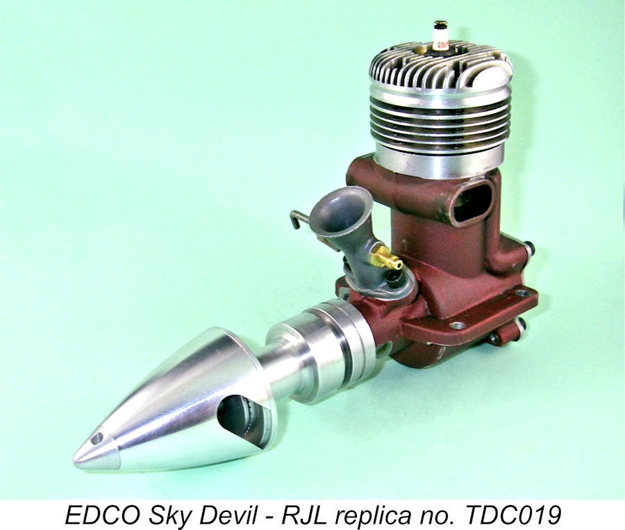 A sideport induction .45 cuin. fixed compression diesel was also planned by EDCO, but it never got past the prototype stage. Ira Hassad later stated that he had nothing to do with the diesel design, although he did recall having test-run one of the prototypes at Del Mar.
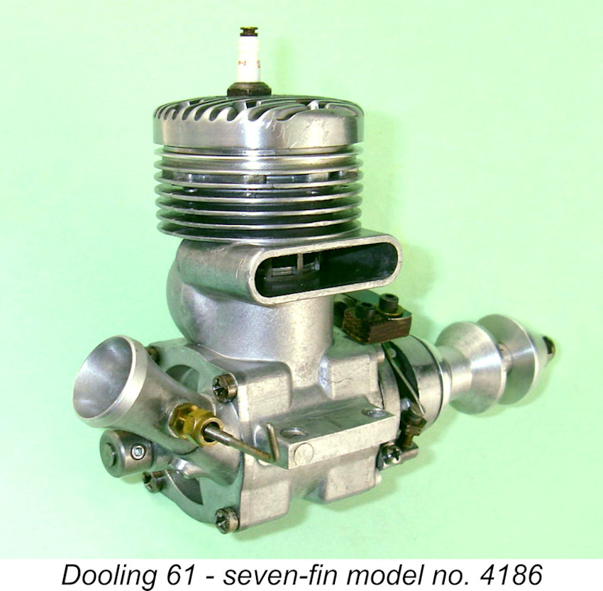 The EDCO Sky Devil never achieved the performance levels of the earlier Hassad Custom model, in large part because it was not individually fitted and assembled as was its progenitor. For an extra charge of $15, Ira Hassad would undertake to rework a Sky Devil to realize its full potential, and a number of smart purchasers took advantage of this. However, the big-bore racing engine market was becoming dominated by the McCoy 60, with the Hornet 60 also still very much in evidence. The arrival of the Dooling 61 later in 1947 did nothing to help. Consequently, the Sky Devil did not meet sales expectations, with only some 1000 - 1500 examples being produced in total before financial difficulties forced the EDCO company into liquidation.
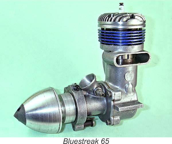 design in which the former EDCO parts and tooling could be used to the extent possible. The design brief this time was specifically for an aero engine for free flight and control-line applications - cars were no longer seen as the major market that they had once been.
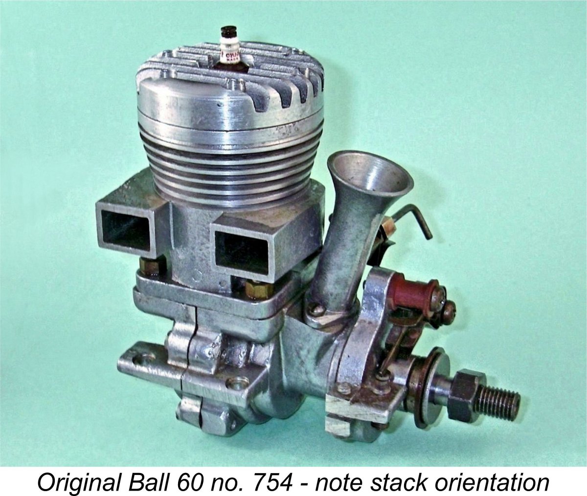 Although he was the most prominent and persistent advocate of FRV racing engines during the period just covered, Ira Hassad was not the only such individual. Over in the small community of Drayton Plains, Michigan, a fellow named Henry Ball had established a facility known as the B&D Racing Engine Laboratory. Here he developed and manufactured another FRV racing engine, the
  The advent of the Ball 60 seems to have paralleled the thinking of another Michigan model engine designer, Wilfred Gibbs Orr of Lansing, Michigan. In early 1945, while WW2 was still ongoing, Orr made a few prototypes of a .604 cuin. FRV twin ball-race unit. These were advertised but seemingly never actually reached the market – it appears that this design fell short of meeting Wilfred Orr’s performance expectations.
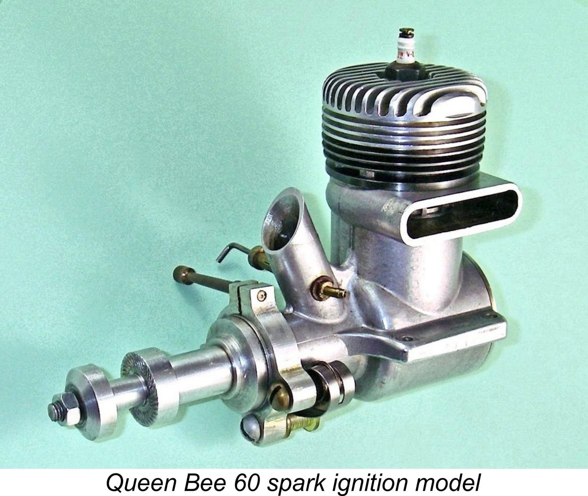
 The design and manufacturing complexity of this engine is such as to imply that they must have had prior experience in the precision engineering field. This was no entry-level model, either in design or manufacturing terms. It's not unlikely that the firm was involved in precision engineering in a broader sense and that the model engines were very much a sideline undertaken as a labour of love. There are many precedents for this.
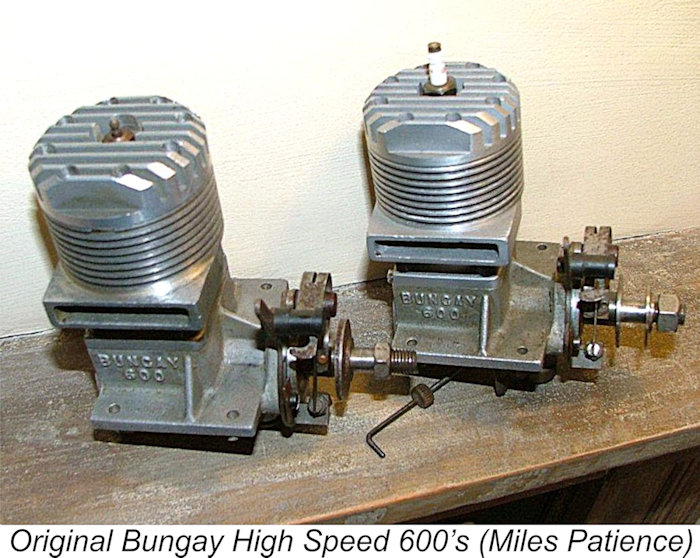 In compiling this section of the article, I was greatly assisted by my good friend Miles Patience of England, who provided a number of images of the two original examples of the Bungay in his possession. The original component images which illustrate this section of the article were all supplied by Miles. I'm very much in his debt!
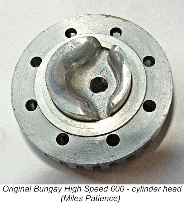 In keeping with normal racing engine practice at the time, the engine featured a cast aluminium alloy piston with a high domed crown incorporating a baffle. The cylinder head casting was formed so as to create a conforming combustion chamber with good swirl-promoting characteristics. The design compression ratio was 9.8 to 1. The plug was slightly offset towards the transfer side to promote more rapid involvement of the pocket of mixture behind the baffle in the combustion process.
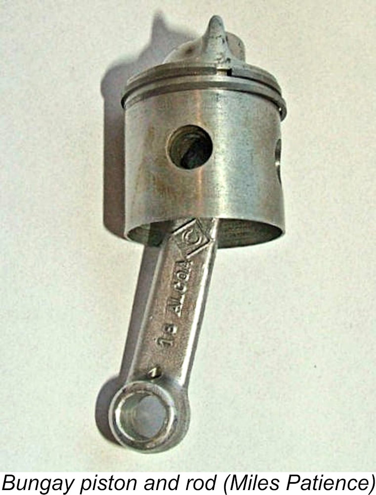 An unusual attribute of the Bungay 600 was the use of steel piston rings as opposed to the more usual cast iron items. The Bartelt replica maintains this material specification. The conrod in the original engines was a drop forging in 14S-T aluminium alloy. Woody Bartelt specified a fully machined rod in his limited-edition replicas, but this does not affect the engine's functionality in any way. The cylinder liner was of heat-treated steel with six square exhaust port apertures separated by the usual narrow columns to prevent ring snag. There were three similar openings to serve as the transfer ports.
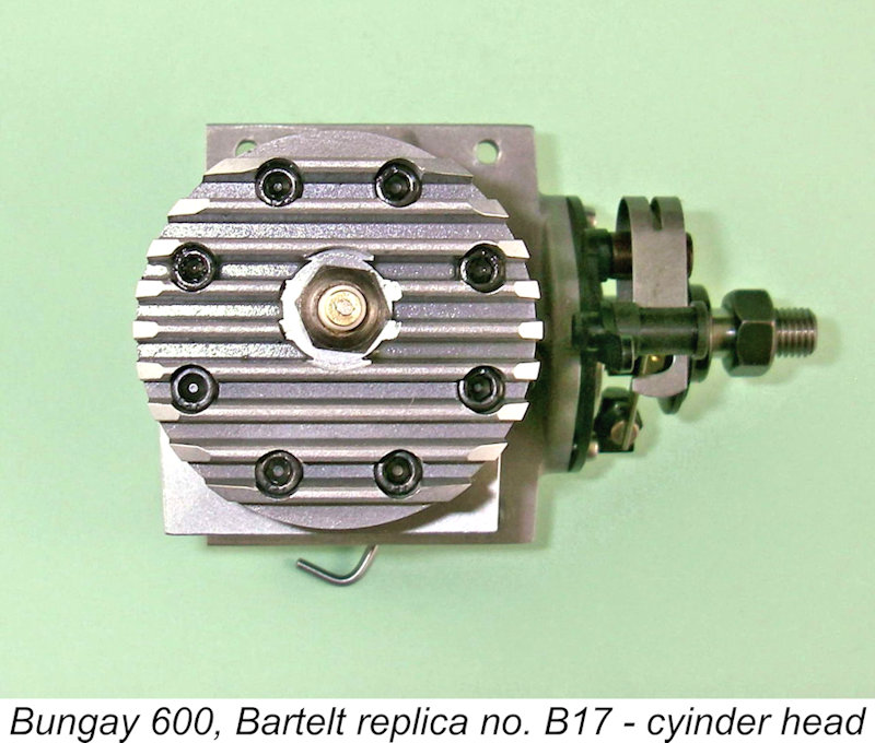 unit. The upper casting incorporated both the exhaust stack and the machined cooling fins. The cylinder head was very securely attached to this casting by no fewer than 8 machine screws, a feature also seen in the contemporary
 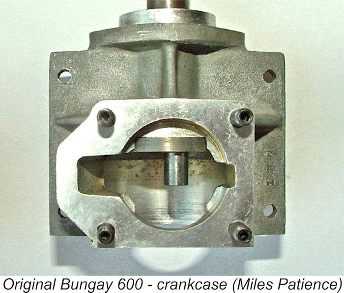 The Bungay designer was clearly concerned with reducing crankcase volume to the extent possible. To this end, the bore for the cylinder liner was not carried through the combined upper and lower castings to intersect the axial bore for the crankweb and rod at full diameter. Instead, it was only carried sufficiently deep to accommodate the liner and the piston at bottom dead centre. This left a number of wedge-shaped metal intrusions which slightly reduced the working volume of the case. The conrod operated through slots milled in these intrusions. The slot on the transfer side was widened considerably to facilitate gas access to the bypass passage. A parallel arrangement was featured in both the
 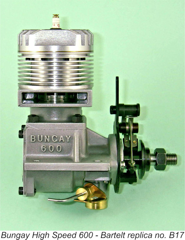 But here the similarities end! A central gas passage having a measured diameter (on the replica) of 0.334 in. was drilled down the centre of the shaft from the rear to provide communication with the FRV induction system. A rectangular induction port of considerable area was cut into the wall of this shaft to register with an opening of similar shape which was machined into the main bearing housing.
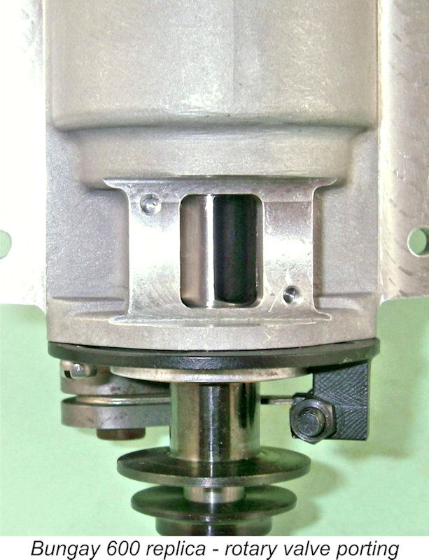 An additional factor which may have had an influence was the issue of fuel feed. With the venturi bore and needle valve design adopted, suction draw would likely be minimal. The location of the intake beneath the engine pretty much guaranteed that the unit would be supplied by gravity from any tank mounted in a rational location, at least with the engine mounted in an upright position as it would normally be in a typical speed model aircraft, race car or hydroplane. Moreover, as the manufacturers pointed out, the engine was virtually immune from flooding with this arrangement - any excess fuel would simply drip out of the intake under gravity.
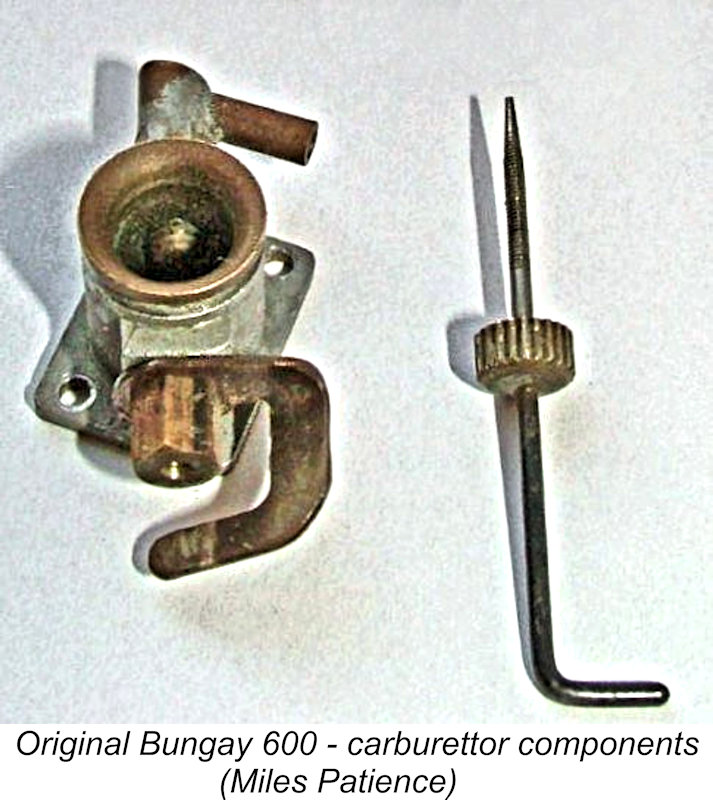 increased fully-open dwell period. For an FRV design, the induction timing was quite aggressive. The Bartelt replica features a full 180 degree induction period extending from 50 degrees ABDC to 50 degrees ATDC.
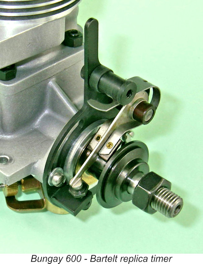 Even then, the location of the intake beneath the engine would have given rise to further problems. It would have been necessary to create an opening in the underside of the pan for the intake as well as cross-drill a passage for the needle valve. Moreover, access to the needle valve in a hydroplane installation would have been severely compromised. In fact, from a mounting standpoint the engine was undoubtedly best suited to model car applications.
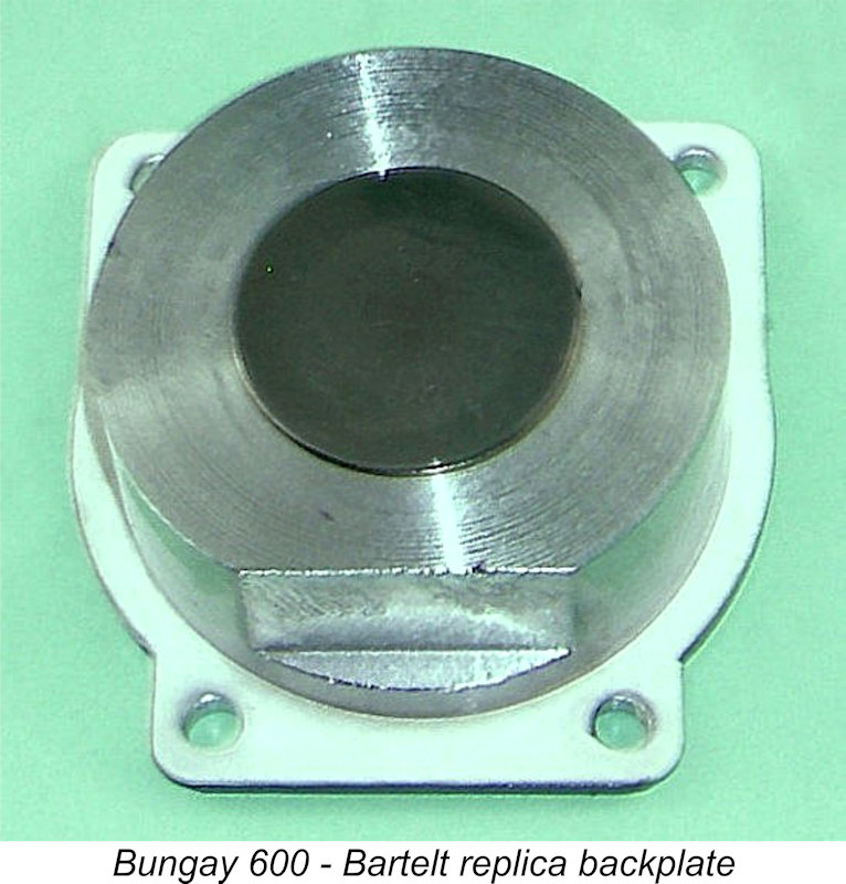 The engine was completed by the use of a cast and machined backplate which was secured by four screws with a gasket to seal. Even here, there was evidence of original thinking. The absence of the usual rotary disc meant that the con-rod was unrestrained from moving to the rear and partially slipping off the crankpin while at the same time scraping metal particles off both itself and the alloy backplate to spoil the engine's working finishes.
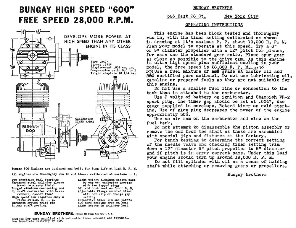
 When discussing an engine of this vintage and rarity, we are generally left with little source material against which to test any present-day evaluation. In most such cases, I would now have said all that there was to be said regarding my subject. Thankfully, in this case we do have a credible contemporary source through which we are accorded a direct glimpse of the design thinking behind this very interesting engine.
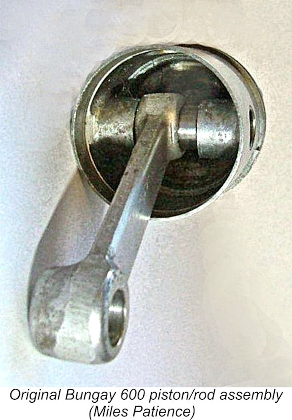 Ingram reported that the Bungay designers were very much aware of the desirability of reducing reciprocating weight to a minimum. To this end, the Bungay employed an unusually thin-walled piston which was cast using what the manufacturers claimed to be their "own exclusive process". The conrod was forged to minimal dimensions consistent with reliability. A relatively thin-walled lightweight gudgeon pin was featured. The rod featured an un-bushed big end bearing with an oil hole for lubrication. Ingram observed weight measurements taken on the Bungay piston/rod assembly against a similar measurement for another unidentified "typical" racing engine of the same displacement. Using the same scale, the Bungay assembly reportedly weighed 205 grains (13.28 gm) against the 290 grains (18.79 gm) of the other unit - a difference of some 29% in favour of the Bungay.
 As far as performance went, the manufacturers claimed in their introductory advertisements that the engine developed 0.96 BHP @ 18,000 rpm. Although generated at unusually high speed, this output was very comparable with reported figures for the blackcase McCoy 60 and the Hornet 60 which were still in production when the Bungay was introduced. However, it was well below the claimed 1.5 BHP output of the new king of the big-bore racing engines, the Dooling 61, and was shortly to be greatly surpassed also by the soon-to-be-released McCoy 60 Series 20.
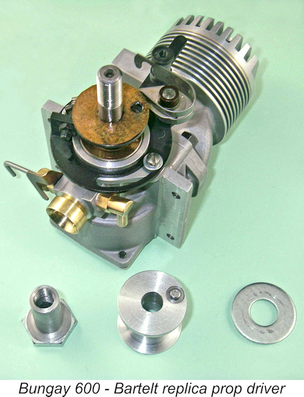
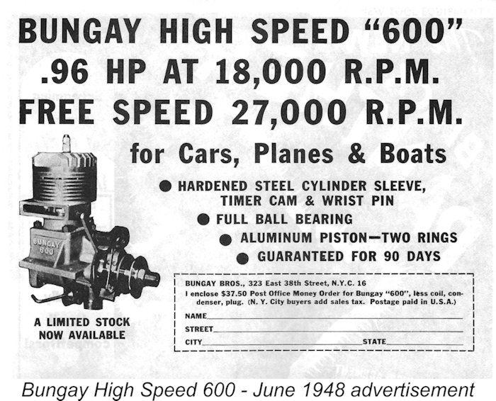 Sadly, this section of the article won't take long! The Bungay was announced in June 1948 through the placement of advertisements in the major modelling magazines. These ads stated that the engine was then available direct from Bungay Brothers from a "limited stock" which was then on hand. The performance claims noted above were prominent in the adverts, as was the fact that the engines carried a 90-day guarantee.
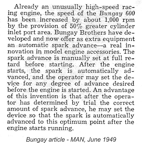
 In his previously-mentioned April 1981 article in "R/C Model Builder", John Pond shared some useful insights into the market failure of the Bungay Hi-Speed 600. He pointed out that while the Bungay was an excellent product in all respects, the 10 cc racing engine market was dominated by West Coast manufacturers such as McCoy, Hornet, Hassad and Dooling, whose engines were used by pretty much all of the leading competitors of the day. This being the case, the arrival of an "upstart" design from the East Coast would have scarcely been noticed. Certainly, none of the leading competitors would have been tempted to switch from their tried and tested powerplants to this new untried model from a distant source.
 | |