
|
|
The Hope .29 cuin. Models
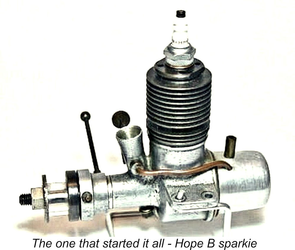
This article is actually a re-organization and expansion of an earlier piece which appeared in installments on the late Ron Chernich’s “Model Engine News” (MEN) website beginning in June 2009. I’m re-publishing it here to prevent its loss as Ron’s now-frozen and administratively-inaccessible site steadily deteriorates due to lack of any opportunity to maintain it. The Hope .29 cuin. models occupy a special place in the history of this range since they represent the only displacement category that was continuously present in the Hope line-up from first to last. Consequently, the Hope 29 series constituted the largest group of different models produced by the company. In this article, I'll take a close look at each of the known models in this category. The Hope B Based upon the evidence of its design architecture, this is the least sophisticated and hence undoubtedly the earliest known design to appear under the Hope designation in any displacement category. These engines are relatively rare today, and even the glow-plug versions still sell for relatively high prices for a complete example in good condition. The spark ignition version is far more elusive, and a nice example would doubtless fetch a pretty fair price.
In my article on the overall range, I noted the reports from Japan that the Hope B engines were related to the earlier Kotobuki ("Grasshopper") spark ignition model. These very rare motors were reportedly made in Saitama Prefecture (just north-west of Tokyo and today part of Greater Tokyo) either during or shortly after WW2. Their manufacturer was a certain Tekkosho Sato, who was apparently involved with the subsequent establishment of the Hope range. I have no idea whether or not he was related to Minoru Sato, maker of the competing Mamiya engines.
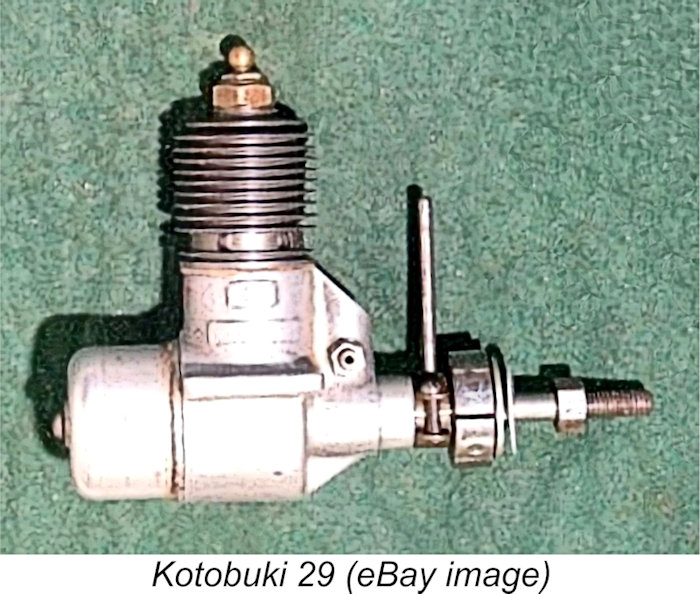
The most prominent external distinguishing feature of the Kotobuki is the placement of its intake venturi in a vertical orientation within a forward expansion of the crankcase casting rather than in a free-standing forward-angled intake tube as on the Hope B. This expansion is cast in unit with the crankcase and main bearing housing. The provisions for model identification also differ - the Kotobuki features two cast-on "panels" on the right-hand side of the case onto which model identification ciphers could be stamped. The accompanying image of an early Kotobuki supplied by reader Peter Gane shows the upper panel occupied by a Japanese cipher of some sort, while the lower panel appears to have been left blank. The use of non-Japanese characters on Japanese products was illegal prior to the end of WW2, making it appear possible that this example is one of those reportedly made during the latter stages of the war or shortly thereafter. The same image shows that the exhaust ports on the original Kotobuki were a radially-arranged series of six simple round holes. At some later date the exhaust ports were modified to form three round-ended slots which appear to have been created by milling away the material between two adjacent holes - the rounded ends are still visible. These ports can be seen in the accompanying eBay images of a complete example.
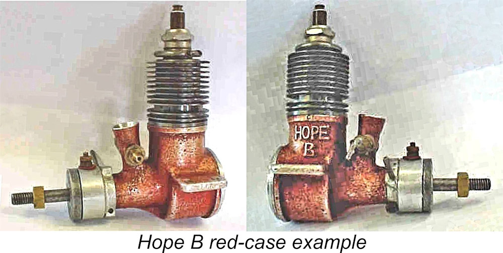
These Kotobuki-based engines do not appear to have been made in large numbers - perhaps they were simply constructed to use up some existing Kotobuki castings. It appears that these hybrids had their cases painted black - both of the images available to me reflect this treatment. I hope (groan!) that the sad-looking example seen at the right received the TLC treatment which it needed so urgently! Regardless, several changes made their appearance rather promptly. In terms of model identification, the two panels featured on the Kotobuki were replaced at the same location by the identification HOPE B cast boldly in relief onto the right-hand side of the crankcase. The extrusion at the front of the upper case which had formerly accommodated the intake venturi was replaced by a separate free-standing forward-angled screw-in brass venturi stack.
The Hope B seems to have been designed to comply with the American Class B rules, as its name would suggest. Long-stroke geometry was applied to the working components, the measured bore and stroke being 17.90 mm x 19.20 mm for a displacement of 4.83 cc or 0.295 cuin - just within the American Class B limit of .300 cuin. Weight of the glow-plug version was a commendably light 6½ ounces, including the plug and tank. The Hope B was a very simple low-tech design which strongly reflected the then-prevailing minimalist philosophy among Japanese technical designers that simpler was better as long as it did the job. Under this design mindset, a given feature was included only if it contributed to performance and/or dependability. The glow-plug version of the engine actually incorporated only 17 individual components, including the needle valve assembly components, tank, tank mounting screw (the only screw used in the assembly), prop nut and prop washer! Moreover, three of these components (tank screw, spraybar nut, prop-nut) were off-the-shelf items, leaving only 14 components to be manufactured. The engine was clearly designed to be produced with a minimal machine tool inventory and the smallest possible number of machining operations, implying something along the lines of a small artisan workshop having limited production capacity, at least at the outset.
The crankcase accommodated a conventional plain-bearing rotary valve crankshaft running in a well-fitted bronze bushing. Both the cylinder and backplate were of the screw-in variety. The spark ignition version of the Hope B featured a very neat enclosed timer apparently similar to that used on the earlier Kotobuki engines. The moving point in both designs was activated by a cam formed by milling a flat in the material of the crankshaft. As mentioned previously, the earlier examples of the spark-ignition Hope B reportedly featured a separate screw-in brass venturi, but this was replaced on later spark-ignition models and on the subsequent glow-plug units with an integrally-cast venturi stack. All surviving examples of which I'm personally aware feature such stacks - I have The design of the one-piece screw-in cast iron cylinder with integral fins and cylinder head necessitated the use of a blind bore reminiscent of the contemporary OK engines as well as the TOP range discussed elsewhere. There were three large radially-disposed sawn rectangular exhaust ports having three internal flute transfers placed between them and overlapping the exhaust to a considerable degree. Port opening periods were actually quite generous. The cylinder was otherwise essentially identical to that used on the Kotobuki engines. As far as is known, most variants of the Hope B spark ignition model (as well as the early glow variants) use 3/8-24 or M10x1.0 thread plugs, although the odd one has been encountered with a ¼-32 thread.
Like many of the Hope engines which were to come, the Hope B featured a screw-in backplate that accommodated an aluminium back-tank. On this early model, the backplate was machined from a sand-casting. The drilled and tapped central boss into which the tank retaining screw threaded had a square section, presumably to facilitate the use of a box-type spanner for tightening the backplate. The tank was left in its natural state with no anodizing applied. It featured an unusually thick brass filler spigot. Interestingly enough, the thread used for the tank bolt was a very British 1/8-40 Whitworth! Presumably the makers had a tap and a source of screws for this thread and just used what was available.
It may be mentioned in passing that the use of metal fuel lines was actually quite common practise in early post-war Japanese model engine manufacturing circles. Apart from the Hope B, the early post-war TOP, Haru, Mamiya and O.S. ranges (among others) also featured models with metal fuel lines, continuing a general trend that had already been well established prior to WW2. It appears that suitable petrol-proof flexible fuel tubing had been difficult to obtain in pre-war and wartime Japan, and the early post-war manufacturers continued to use metal tubing even after the imperative for doing so had passed. An example of technical inertia, perhaps.
Two of the three original glow-plug examples of this engine in my possession arrived as rusted-up basket cases, one having a broken con-rod to add insult to injury. This necessitated their complete dismantling for restoration. The restoration of one of these examples seen at the right is fully documented in a separate article to be found on this website. The failure of the cast aluminium rod in the other example had occurred in the very thin band of material that surrounded the bronze bushing for the big end (see illustration below at the left). This failure could undoubtedly be attributed to the fact that the big end bearing was bored considerably off centre, leaving an almost paper-thin band of material on the side on which the failure occurred.
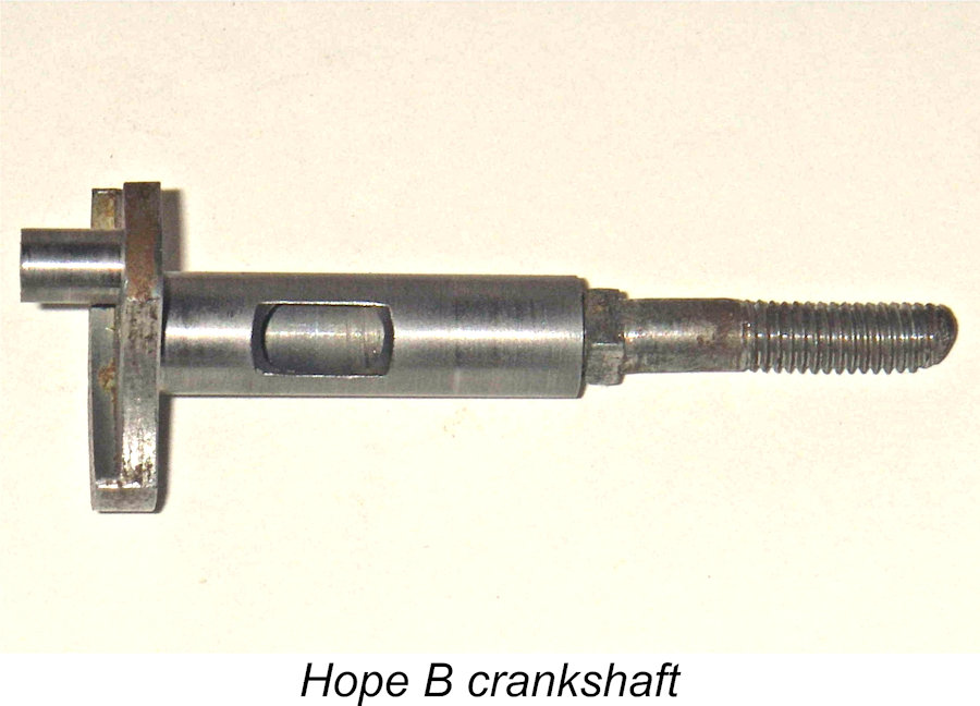
The gudgeon pin is quite interesting in that it is in fact a steel stud which is threaded at one end and slotted for a screwdriver at the other. The pin passes thread-first through the single open boss and through the small end of the rod to screw into a tapped blind hole which serves as the other boss. The idea was clearly to prevent the pin from turning in the bosses and also to prevent it from fouling any of the ports. But its security seems rather suspect to me and worth checking periodically if you plan to run one of these critters. This appears to be another hang-over from prewar practice, when Japanese designs such as those from Inoue and Ishizue used similarly-designed gudgeon pins. The crankshaft is of 10 mm diameter with a 7 mm diameter gas passage drilled through it. The shaft runs in a conventional bronze bushing set into the case. The induction port is of surprisingly up-to-date design, being of rectangular form for rapid opening and closing and having a generous length of 11 mm. The aluminium alloy prop driver disc on all three of my examples has a square central opening which fits snugly onto a square box section milled onto the shaft. The crankweb is very heavily counterbalanced, to the point that the rod had to be made asymmetrical in side profile to clear the counterweight. This became a bit of a trademark approach with the Hope engines, although the arrangement tends to impose elevated bending stresses on the rod and crankpin as well as uneven wear on the rod bearings. It may indeed have contributed to the observed failure in one of my own examples. My milled replacement rod for the damaged engine was made considerably sturdier than the broken original! One point to watch when re-assembling these engines is that the gudgeon pin should be assembled from the rear so that its threaded end is at the front. This is because the use of an asymmetrical conrod tends to place the major loads at the rear of the gudgeon pin, and it's not desirable that this end should have any exposed thread to create accelerated wear in the conrod small end. My Despite the rather "basic" look of this engine, the workmanship is first-class where it counts, and all running fits in my three original glow-plug examples and my converted sparkie remain outstanding despite the considerable amount of use and abuse to which all of these engines have clearly been exposed. All of this supports the notion that these units were hand-built by a small-scale workshop which had rather basic equipment and somewhat limited access to materials but was staffed by a few highly competent model engineering types who knew how to get the best out of what they had. OK, now we know how it goes together. Next question - how does it run?? Here I can only comment on the basis of my own limited operating experience of these engines in glow-plug configuration. For a start, filling the tank requires patience because there's no air vent and venting of the tank during filling is entirely dependent upon leakage from the access hole through which the brass fuel pipe enters the tank. The fit of the pipe in this hole is sufficiently loose that it leaks just enough to allow the tank to be filled with a little patience.
The three original glow-plug models in my own possession all differ in detail from one another, and in fact the Hope B evidently underwent a series of detail modifications throughout its production life. Among other things, the standard plug installation thread was changed at some point from 3/8-24 (or perhaps M10x1.0) to ¼-32. One rather subtle modification which is tricky to spot is the fact that at some stage during the engine's career as a glow-plug model the compression ratio was raised. On the basis of some eye-dropper measurements of combustion chamber volumes at top dead centre, the original compression ratio seems to have been of the order of 7:1 - pretty typical for spark-ignition engines of the mid 1940's, but rather marginal for glow-plug operation using low-nitro fuels. At some later date they went to a slightly higher compression ratio of 8.5:1, a far more suitable figure for glow operation.
I have also encountered at least one 9-fin example with the higher compression ratio, so the external shortening of the cylinder seems to have been something of an afterthought. It appears that they first raised the compression ratio by boring the cylinder internally to a slightly lesser depth (leaving less volume at top dead centre) and then realized that this would allow them to shorten the cylinder externally as well, thus saving a little weight. One word of caution in passing - the fins on the Hope B are very thin, and the fact that they're machined from the relatively brittle cast iron makes them extremely vulnerable to damage. I have actually encountered very few examples of the Hope B that didn't feature at least one broken fin. Please exercise care to avoid adding to their number! The detail modifications typified by the variations in cylinder dimensions are by no means the only such changes. My English informant Alan Strutt put a fair bit of effort into attempting to sort out the various design variations of the engine which may appear from time to time. While there are no hard and fast boundaries, the main variants may be characterized as follows:
In reality, the design probably changed in detail almost continually over the engine's production life as the manufacturers gained further experience and insight. It's likely that changes to individual components were so frequent that it's impossible to state authoritatively that there was a given number of specific variants! The Hope "New 29" - First Model It's clear that the Hope B must have been sufficiently well received to encourage the makers to embark upon a program of further development of their 29 model to bring it up to the more contemporary specification of its ever-improving competitors. In all probability, this move was forced upon Hope by the rapid development from 1949 onwards of superior 29 models from O.S., KO, Fuji, Boxer and Mamiya, who were soon to be joined by Enya in 1952 when that maker introduced its initial 29 offering. The rather antiquated-looking Hope B clearly couldn't compete with these designs, making a fresh approach imperative. The resulting design was the original version of the Hope "New 29" model, which I will now describe.
Whenever it took place, the replacement of the Hope B by the New 29 coincided with a general switch to die-casting for the overall Hope range. Certainly, the New 29 used die-cast alloy components throughout. In developing their 29 to the next stage, the makers of the Hope engines effectively threw away their earlier 29 design and started afresh, taking their existing 19 model as their basic pattern. The New 29 abandoned the radial porting of the Hope B in favour of the more fashionable loop scavenging set-up first used by Hope in their earlier Super 60 racing model and subsequently applied to their companion 19 model of 1949. It also used die-castings which were left more or less in their as-cast form apart from some basic clean-up, just as in the revised die-cast model of the Hope 19 which appeared at more or less the same time (see my separate article on the 19 series).
It's necessary to exercise great restraint before citing the undoubted existence of a single example as evidence that all examples of this early variant used magnesium castings. During the early post-war period, Japanese model engine manufacturers faced considerable difficulty in obtaining suitable materials for model engine construction - their activities were low on the national priority list, and such quality materials as were available were unquestionably earmarked for the nation-wide reconstruction effort then underway. Model engine manufacturers doubtless had to make do with whatever they could get at any given time. Hope (or their casting contractor) may well have obtained a batch of magnesium casting alloy from somewhere and used it for a few examples of their new .29 design simply because that way they could keep producing engines! It's entirely possible that other examples were made using aluminium alloy.
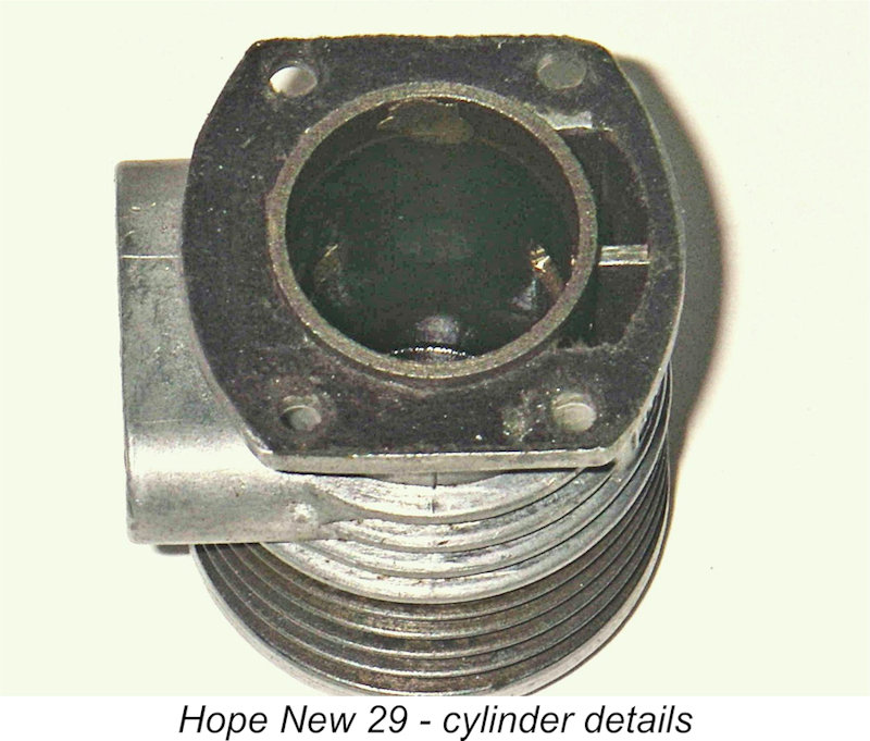
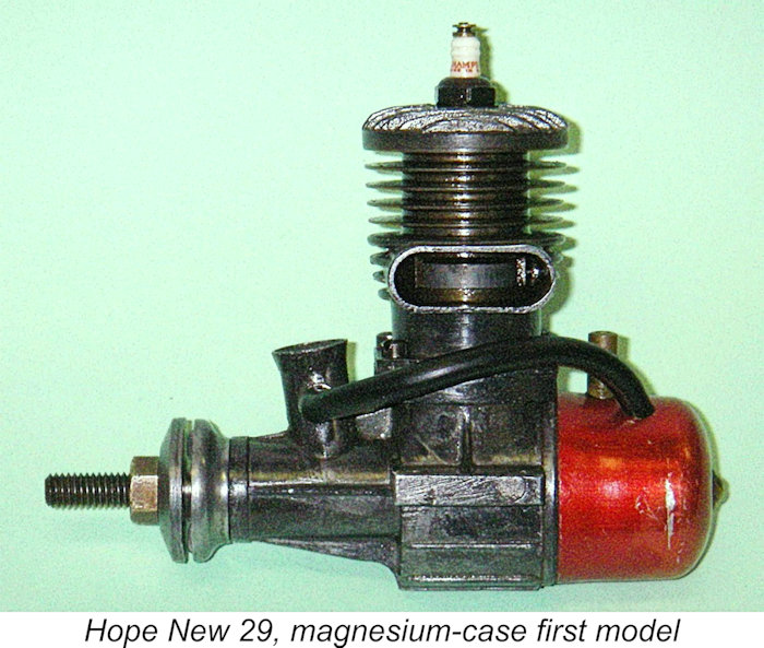
As in the Hope 19, a straight-baffled cast-iron piston was employed along with a conventional 4 mm dia. gudgeon pin, now fully floating and equipped with brass end pads. In this initial version of the New 29, the blind bore of the Hope B was retained but the engine was considerably"prettied up" by the addition of a separate cast alloy cylinder head which was attached to the The makers had also decided to abandon the long-stroke geometry of the Hope B in favour of a more contemporary short stroke design. Measured bore and stroke of the New 29 were 18.5 and 18.0 mm respectively for a displacement of 4.84 cc (.295 cuin), still taking full advantage of the American Class B displacement limit. Weight had crept up just a little, being measured for the illustrated example as 6¾ ounces with tank, plug and fuel tubing. The die-castings used on the New 29 are worthy of comment insofar as they are actually quite complex and represent a relatively high level of effort and expertise on the part of the makers, particularly given the use of magnesium alloy at this early stage. The revised main crankcase casting was split horizontally at the top of a substantial flange cast just above the top of the crankweb. A separate cast alloy lower cylinder jacket The cast iron cylinder had integrally-turned cooling fins and a blind bore (both carried over from the Hope B) with a plain lower spigot length below the fins which fitted into the installation bore of the upper casting and incorporated the exhaust and transfer ports. A short length of cylinder protruded from the base of the upper casting's installation flange to act as a spigot in locating the upper and lower castings very securely. Interestingly, the cylinder was not retained within the upper casting by screws but was attached to the casting by a pair of brazed welds located fore and aft. It was thus impossible to separate the cylinder from the upper casting. These two welds were solely responsible for keeping the cylinder in place. Shades of O&R influence here, and the same set-up was also used by Mamiya at around the same time. One of these welds is visible in the accompanying image. But there was a difference in the approach taken by Hope - in the case of the New 29, the welds were applied from the inside of the bore through a pair of opposing holes near the bottom of the liner at the point where the bore was slightly relieved (see image). This means that they must have been applied before the bore was finished, since the piston operates in direct contact with the finished weld surfaces.
It appears not unlikely that the intent of this arrangement was to offer enhanced appeal to both American and European markets, which had up to this time tended to favour left and right-hand stack placements respectively. The cost of this flexibility was a slight increase in complexity and also in crankcase volume, although the latter was probably not really significant. Another noteworthy feature of the illustrated magnesium-case example of this model is the fact that the conrod was cast in the same dark-hued magnesium alloy that was used for the main castings. Although very light, magnesium alloy appears The counterbalance on the crankweb is extremely thick and extends back to almost half of the crankpin length. This was a common design characteristic of the Hope engines which necessitated the use of an asymmetrical rod similar to that seen on the earlier Hope B. The rod column is offset well to the rear of the two bearing centres, this being necessary to provide clearance for the counterbalance. I would expect elevated cyclic bending stresses and/or uneven bearing wear to result from this arrangement. Since the illustrated example has had very little running, it provides no basis for making any judgements in this regard.
The four screws used to hold the castings together at the split are rather individualistic items, featuring higher-than-normal
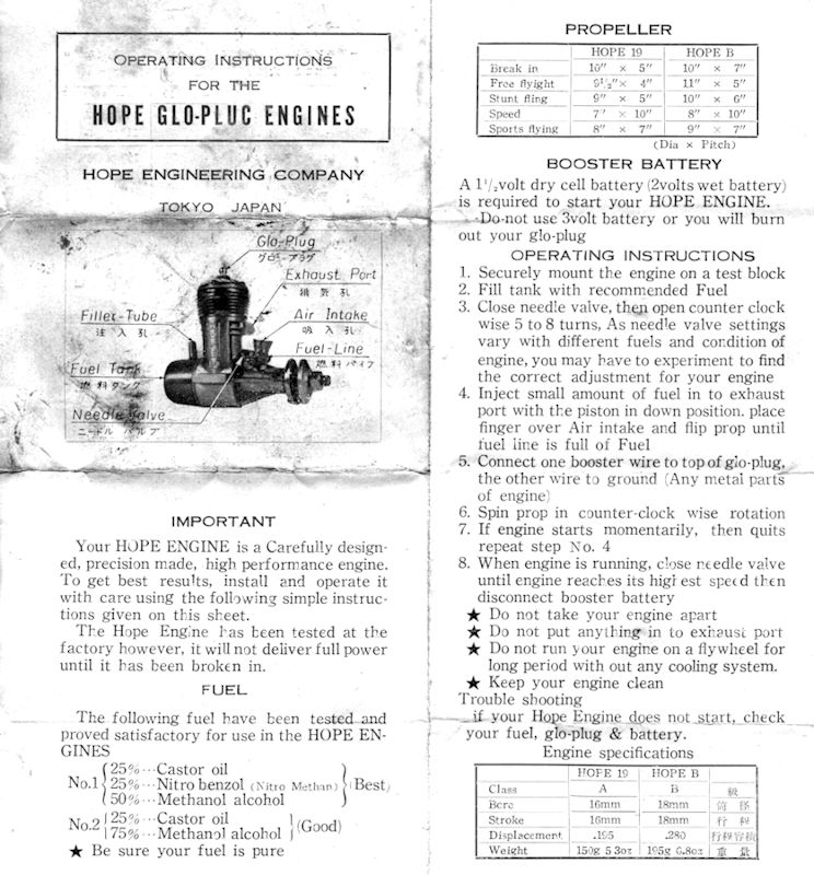
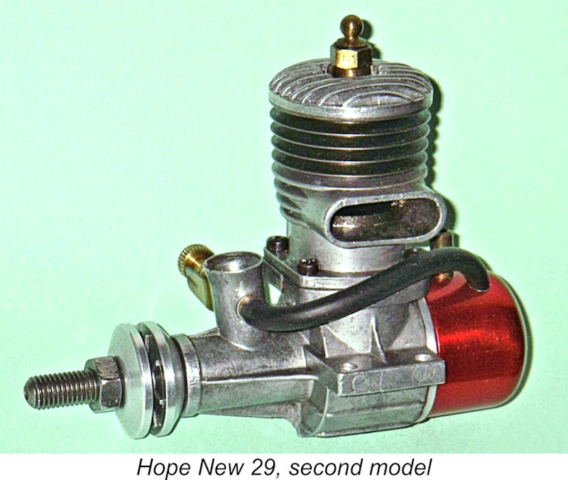
The engines were also supplied with a concise and well-written set of operating instructions which were presented in both Japanese and very clear English. The English-language side of the instruction sheet is reproduced at the left. The illustrated example of the engine is extremely well made and fitted. This example has had very little running and has never been mounted. All working fits are beyond reproach and compression is outstanding, with no trace of stickiness in the bore. Since I really don't trust that magnesium alloy rod, I have no plans to run it myself. Examples of this variant of the Hope New 29 appear to be extremely few and far between, even in Japan. It seems likely that the design was amended, most probably as a result of hard experience, after only a few examples of this initial version were made. Indeed, it may have been more of a short-lived "experimental" model than anything else. The Hope "New 29" - Second Model It seems that the experiment with the use of magnesium alloy in the original New 29 model was not viewed by Hope Engineering as a success. In all likelihood, one of the factors involved here was the fire hazard associated with the use of such material. Magnesium alloys are inflammable if heated sufficiently, and the fact that the cylinder liner was retained in the upper casting by spot welding must have challenged the manufacturers in this regard. The E.D. company of Great Britain experienced several fires in their factory arising from their use of magnesium alloy, and it was apparently this issue as much as anything else which prompted them to switch to aluminium alloy in the late 1950's.
Apart from the fact that all castings were now of aluminium, the resulting second variant of the Hope New 29 was externally more or less identical to its predecessor. Inside, however, there were several quite significant changes. The first of these was the design of the connecting rod. I noted previously that the magnesium alloy rod of the original New 29 appeared rather undernourished for an engine of this displacement. It appears that actual experience had convinced Hope Engineering that some beefing-up of this hard-working component was in order.
And that wasn't all - the design of the induction port in the crankshaft was also changed. The original port had been formed in two operations - the milling of a "flat" in the shaft surface followed by the milling of an offset oval "slot" to communicate with the internal gas passage. The revised port did away with the initial operation (machining the "flat") and instead involved only the milling of an oval These changes may indicate that problems had been experienced with the original design of the New 29. It appears that both the rod and the shaft had been found wanting in the longevity department, forcing the changes documented above. My pristine example of the very rare first model has undoubtedly had (and survived!) its factory test run, but I have no plans to tempt fate by running it further!
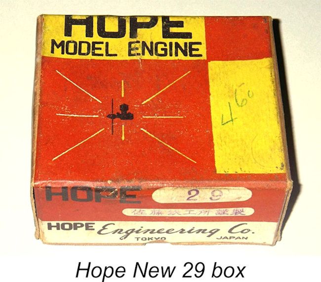
As with other Hope models from the early period, it's extremely likely that minor variations of this model will be encountered. The manufacturers were clearly still in their development phase when this version was introduced, and further minor modifications may well have been made from one production run to the next. As an example, I’m aware of two different backplate styles, both of the screw-in variety but having slightly different web patterns in the recess. In addition, some examples (like the one illustrated at the left) had un-anodized tanks. The engines were still supplied in the attractive red-and-yellow boxes described earlier. As stated previously, these engines do not carry serial numbers as a rule. The sole presently-known exception is an example of the second model just described which bears the number U298 stamped neatly into the left mounting lug. This may or may not be a factory marking. The Hope "New 29" - Third Model Based on my own tests, the previously-described version of the New 29 offered a substantial improvement over the old Hope B in terms of performance and durability. However, it seems likely that it didn't take the Hope Engineering Company long to recognize a few residual limitations inherent in their revised design. One of these was undoubtedly the cylinder head. The continuing use of a blind bore made it impossible to contour the head to match the baffle piston or to provide anything like the then-fashionable hemispherical shape which in theory at least promoted some degree of swirl and gas concentration in the combustion chamber to improve the engine's combustion characteristics. The need for baffle clearance also limited the upper range of available compression ratios. In addition, the type of construction employed meant that if a replacement piston/cylinder unit was required either as a result of wear or due to crash damage, one had to buy the entire cylinder assembly from the case upwards - piston, cylinder, upper casting and "dummy" head. One might almost just as well buy a new engine! Furthermore, other manufacturers had not been idle. The introduction in April 1952 of the excellent and far more "modern-looking" sand-cast Enya Typhoon 29 Red Head and the appearance of the vastly improved Fuji 29 Silver Arrow later in the same year clearly required a further response if Hope were to remain in the model engine business with their 29 as their "flagship" model.
The bottom half of the engine from the crankcase split on down was unchanged in this new variant. However, the cylinder assembly was completely different. The upper casting was altered to incorporate not only the bypass passage and exhaust stack but the cylinder cooling fins as well. The blind bore was now a thing of the past - the revised model used a conventional drop-in cylinder liner. This liner was apparently shrunk-fitted into the upper casting - there are no signs of any welds, but all attempts to remove the liner by fair means meet with failure.
The four lower screws which attached the upper casting to the main case continued to be of the rather odd-ball M2.5x0.7 coarse thread variety. However, the four head screws were more conventional M3x0.6 items. As noted earlier, the coarser thread was doubtless used at the case split to minimize the possibility of stripping the light alloy threads in the lower case. In the case of the cylinder head, though, the imperative was to maintain a seal against combustion pressures, hence the use of finer-pitch screws which applied greater force for a given torque. But these screws too were matched with aluminium female threads, and the approach taken to minimizing the possibility of stripping in this instance was to increase the diameter of the screws.
The production changes to move from the previous version of the New 29 to the one just described were not great. Apart from the different approach to the provision of the cooling fins and the cylinder head, the two versions remained essentially identical. They both utilized identical main crankcase castings and working components. The same screw-in backplate with attached tank was also carried over from the previous model, together with the red-anodized tank. My example of this model is a match for the earlier Hope engines in another important respect - it is just as well fitted. The illustrated example has clearly done a lot of work in its time, but all fits remain absolutely first-class apart from some minor wear in the rod bearings. The engine still starts and runs really well.
Although the Hope range had yet to make any real impression in the world marketplace, reports from Japanese contacts indicated that the engines were still selling well in Japan at this time. Certainly, the domestic public response up to this point must have been sufficiently encouraging for the company to consider it worthwhile to continue their development program to meet the emerging challenges from rival Japanese manufacturers. The resulting revised models were the Hope "Super" 19 and 29 series, of which the Super 29 was the flagship product. The Hope "Super 29" The introduction of the updated third model of the New 29, most likely in late 1952, didn't provide the Hope Engineering Company with much of a breathing-space. The revised New 29 still lacked any real edge over the competition, and by the middle of 1953 both Enya and O.S. were hard at work developing improved .29 cuin. models to replace their existing offerings. Once again Hope were placed in a position where they had to either develop a further upgrade of their 29 model or throw in the towel. To their credit, they chose the former route, seemingly confirming that at this stage their products were continuing to maintain a reasonable foothold in the marketplace, at least domestically.
The Super 29 was a thoroughly up-to-date and generally very well-executed design that bore a strong resemblance to the then-current K&B 29 Greenhead model. Once again, Hope threw the book out the window and started afresh. The new design reverted to a one-piece die-cast aluminium alloy crankcase with left-hand exhaust stack, similar to that which had been introduced on the original Hope 19 described elsewhere. However, the former screw-in backplate and back tank were now gone, being replaced by a more conventional American-style backplate secured by four screws and having no provision for a back tank.
The cylinder was attached to the main casting by three long screws which passed vertically downward through the cylinder head and cooling fins to thread into tapped holes in the main casting, with three additional screws providing additional security for the die-cast aluminium cylinder head. Another innovation with this model was the fact that all castings were given an attractive matte finish which was apparently produced by vapour-blasting. The three long slot-head screws which attached the cylinder assembly to the case were still of the oddball M2.5x0.7 variety. However, the three short supplementary head screws were now conventional M2.5x0.45 slot head items. No doubt the difference was due to the differing metals involved - the coarse threads were used where the female thread material was aluminium, while the finer threads were used in steel. Suggestion - do not lose or strip those long screws!
By now the Hope designer was well and truly in the over-square camp as far as the 29 model was concerned - the measured bore and stroke of the Super 29 are 19.0 mm and 17.00 mm respectively for a displacement of 4.82 cc (.294 cuin.). The engine's checked weight is a commendably light 6¼ ounces. As far as is known, none of these engines bore serial numbers. A word of advice to any owner of one of these "Super" models who may be tempted to take it apart to see what makes it tick - don’t! By all means take the backplate off if you really want to have a look at the rod and crankweb. But leave the cylinder assembly well alone! The steel of which the cylinder and fins are made is rather flexible, and the cylinder wall and top fin were made unusually thin. In addition, assembly stresses are carried down to the upper crankcase by the very thin cylinder walls. Consequently, the tightening down of the assembly screws inevitably "sets" the cylinder into a slightly distorted shape dictated by the stress patterns established by the tightening. The running-in process redistributes the cylinder stresses to a degree and also accommodates the piston to the cylinder in its tightened and "settled" configuration. If a run-in engine is dismantled and re-tightened it is well-nigh impossible to regain the original "set" precisely. Consequently, the engine has to be run in all over again, with results that cannot be completely predicted! The Final "Super 29" Engines Subsequent to the original publication of this article on MEN in 2009, I acquired another example of the Hope Super 29 which provided opportunities for further research. The engine came with its original box and appeared to be unrun. The reason for its unrun state became immediately clear upon close examination - it had suffered the all-too frequent fate of having been tampered with by an original owner who just had to have a look inside before running the engine but lacked the basic knowledge required to carry out the re-assembly process correctly. There is no more dangerous owner than the guy who thinks that he knows what he’s doing ……………and doesn’t!
More significantly, he had re-assembled the engine with the cylinder set at 120 degrees from its design location such that the transfer port connected the bypass passage with the exhaust stack! The head was correctly positioned, so I only became aware of this error when I first handled the engine and immediately noted the complete absence of base compression when turning over. A look though the exhaust stack made the reason very clear! This is a first for me - the usual trick is the installation of the piston with the baffle on the exhaust side!
On the plus side, this process allowed me to document a few internal details which were hitherto unclear. The rod is a cast item of typical Hope configuration in that the column is set well aft of the bearing centres to provide clearance for the large counterweight on the full-disc crankweb. The column is quite wide but is fairly thin and frankly looks a bit on the flimsy side to me. However, the measured The solid steel gudgeon pin has a diameter of 4 mm, allied with a 6 mm crankpin diameter. No end pads are used on the gudgeon pin, which instead has smoothly finished rounded ends - probably quite OK with a steel cylinder. The piston is extensively machined away internally to lighten, with the extra band of metal provided internally for the piston bosses being milled away at the sides as well as being undercut below the piston crown. Overall, the piston is a very well-designed item having ample strength and generous bosses coupled with very low weight for a cast-iron component.
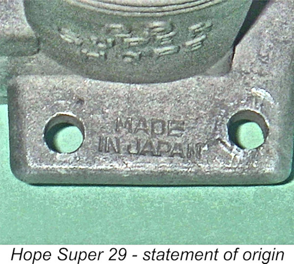
The die-cast cylinder head features a hemispherical combustion chamber with a slot for the piston baffle - more or less identical to the head featured on the third model of the New Hope 29 described previously. It was clear from the condition of this component, and indeed the rest of the engine, that this example has never been run at any time, not even at the factory. Evidently Hope did not test their engines, at least during the latter stages of their existence. The minor mounting marks on the two front mounting holes (left and right) appear to be from a display mount. The rear mounting holes are clearly unused. The engine exhibits one structural change from other Considerations of the engineering logic involved suggest that this change represents an attempt on the part of the manufacturers to deal with the previously-mentioned issue of cylinder distortion due to the assembly One other very small non-structural detail sets this example apart from the others. The statement “Made in Japan” appears stamped in rather small letters onto the upper surface of the right-hand mounting lug. This stamping was clearly done prior to vapor-blasting. The implication appears to be that the makers expected to sell a fair number of these engines in English-speaking markets.
Accordingly, they acquired a stock of plain cardboard boxes and had a simple stick-on label printed which announced that the contents were a Hope engine but gave no information whatsoever regarding the manufacturer. This makes perfect sense when we realize that the manufacturer was no longer in operation as such when these boxes were packed! It thus appears highly likely that my later acquisition is an example of the Hope Super 29 in the final form in which it was sold. End of the Line As events were to prove, the Super 29 was destined to be the final Hope 29 model. It's presently unclear exactly when production of these engines ceased, but it was certainly during the latter half of the 1950's. The range was still in existence when Peter Chinn's very informative summary of Japanese engines entitled "Made in Japan" appeared in the November 1956 issue of "Model Airplane News". The Hope 19 and 29 engines were mentioned in this article and two illustrations showing the Hope Super 19 were included. We may legitimately conclude that the range was still in production as of 1956. However, the absence of any further authoritative references makes it appear unlikely that production continued very far beyond 1956. It's true that Hope models in the .09, .19 and .29 categories were included in the list of the world's model engines which appeared in early 1958 in the British publication "Model Aero Engine Encyclopaedia". However, inclusion in that list cannot be taken as conclusive evidence of ongoing production as of 1958 - a number of engines on the list were unquestionably out of production by that time, some of them for years. In any case, the list was almost certainly compiled during the latter part of 1957, when the last engines may well have still been available. If I had to hazard a guess (and it would be no more than that), I’d probably opt for 1957 as the year in which Hope production most likely ceased. The final blow was likely the introduction at around that time of the outstanding Enya 29-III and the equally fine O.S. Max-II 29, both of which simply blew the Hope away in performance terms. The further activities (if any) of the Hope Engineering Company are presently unknown to me. _________________________ Article © Adrian C. Duncan, Coquitlam, British Columbia, Canada First published on MEN June 2009 This revised edition published here July 2025 |
 In a
In a 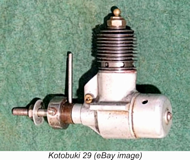 According to Mike Clanford's often-unreliable but nonetheless very useful
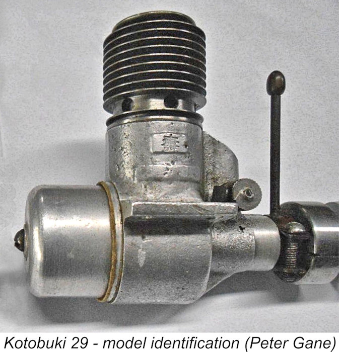
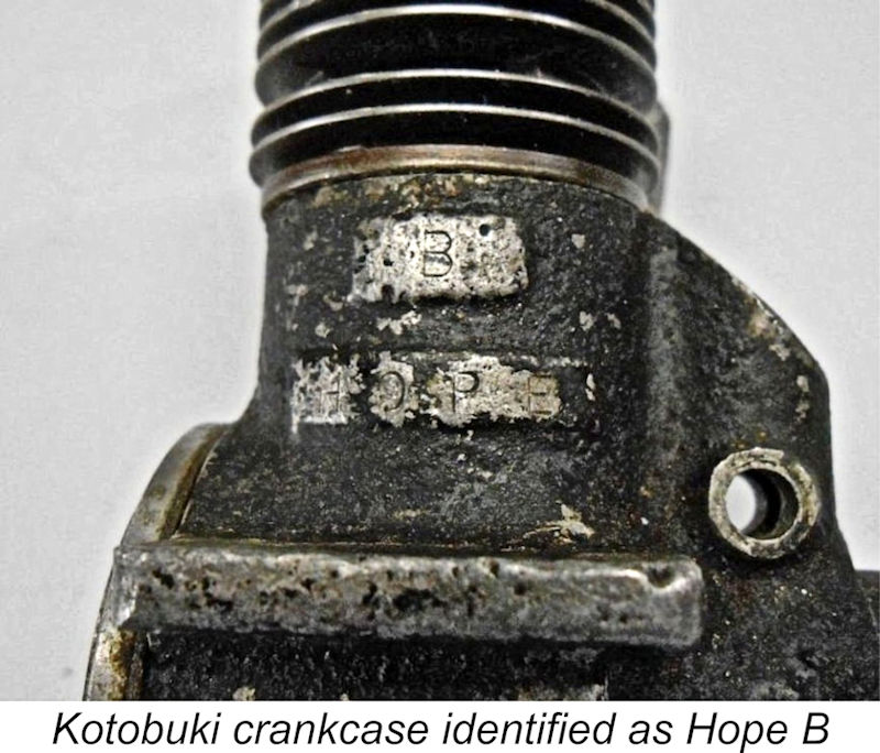 As stated earlier, reports from Japan credit one Tekkosho Sato with the production of the Kotobuki and the subsequent establishment of the Hope Engineering Co. which manufactured the Hope range. This appears entirely plausible based on the physical evidence, since the earliest clearly-identified examples of the Hope B utilized Kotobuki cases with the letter B stamped into the upper panel and the word HOPE appearing in the more elongated lower panel, as seen in Peter Gane's accompanying image at the left. There's no question that the same case was involved.
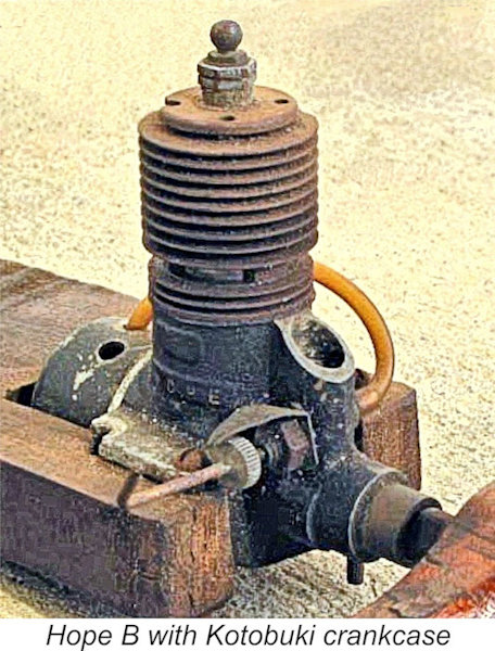
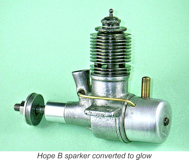
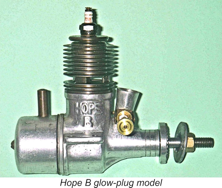
 However, even this latter modification didn't last long - examples of this variant are extremely rare, to the point that I've never seen so much as an image of one myself. A further change was made quite quickly to an integrally-cast forward-angled venturi stack which was cast in unit with the main bearing housing and crankcase. It must be admitted that this feature was far more vulnerable to crash damage than the former Kotobuki arrangement. However, it was to remain a feature of the Hope B design for the balance of the engine's production life. The example illustrated at the left is an original spark ignition unit which has lost its timer, subsequently being converted to glow-plug operation with a turned aluminium alloy cap pressed on to cover the timer mounting. In this form it starts and runs very well.
 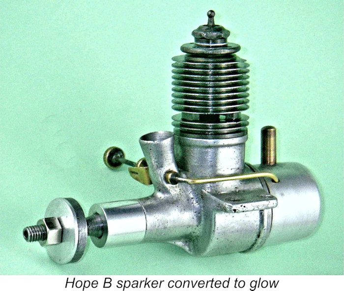 In keeping with this notion, a very plain but sturdy one-piece sand-cast crankcase was used. This component is quite a contrast to the very fine die-castings that had already been produced in Japan prior to the end of WW2 and which were to be further refined over time by Japanese model engine makers (including Hope themselves). No attempt was made to polish or otherwise enhance the finish of the casting apart from what appears to be a light brushing treatment and the application of a painted finish to some examples. The Hope B name was cast in relief onto the right side of the case (looking forward). The beam mounting lugs were set well above the plane of the crankshaft's axial centre-line.
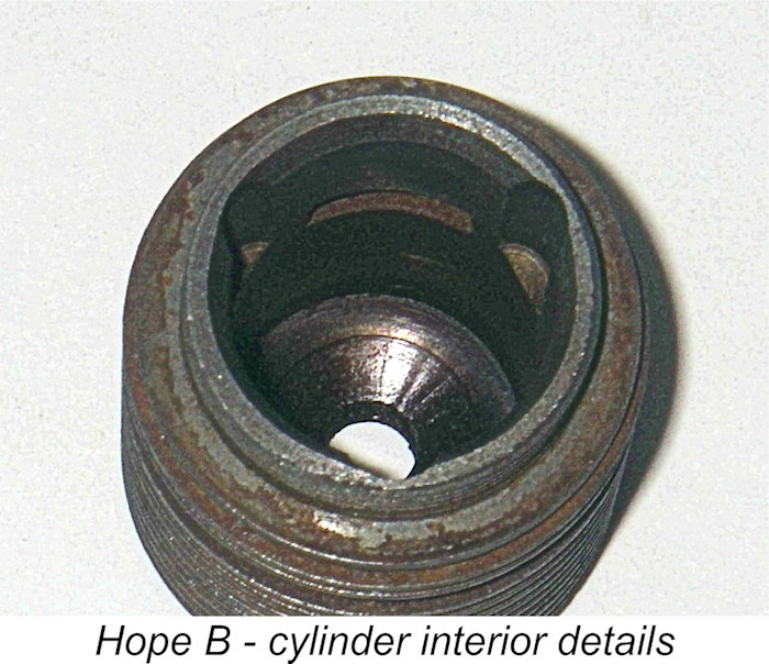
 Anyone who likes the metal-pipe plumbing on the
 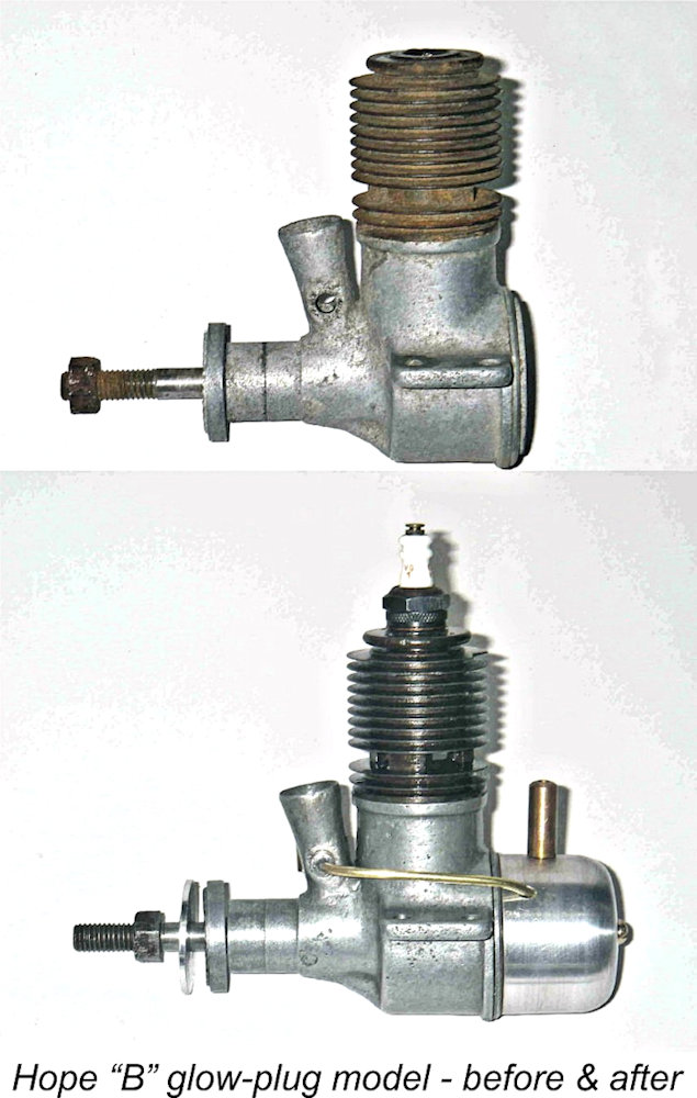 An externally-threaded steel needle was used. This threaded into the spraybar, with tension being provided by a knurled disc part-way along the needle which engaged with a conventional two-sided brass spring ratchet. A further knurled disc was fitted to the outer end of the needle to provide a convenient grip for adjustment. Rather McCoy-inspired at first sight, but the fact is that this style of needle was used extensively before the war on Japanese engines. As events were to prove, Hope were to stick with the externally threaded needle design for the full production life of the range. Such needles are notoriously vulnerable to crash damage, but there's no denying the fact that they provide very fine needle control.
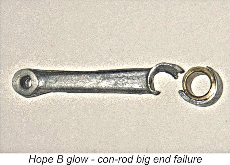 The use of long skinny rods (often die-cast) was well established in Japan by this period. The Hope B's designer may not have fully appreciated the fact that the more open porting and improved induction of crankshaft rotary valve designs such as the Hope B would result in an engine that ran more strongly than its side-port predecessors and hence tested its working parts more severely. This would be especially true of the glow-plug versions given the greatly inferior control over ignition timing that this type of ignition embodied and the relatively high speeds for which such engines had to be loaded in consequence.
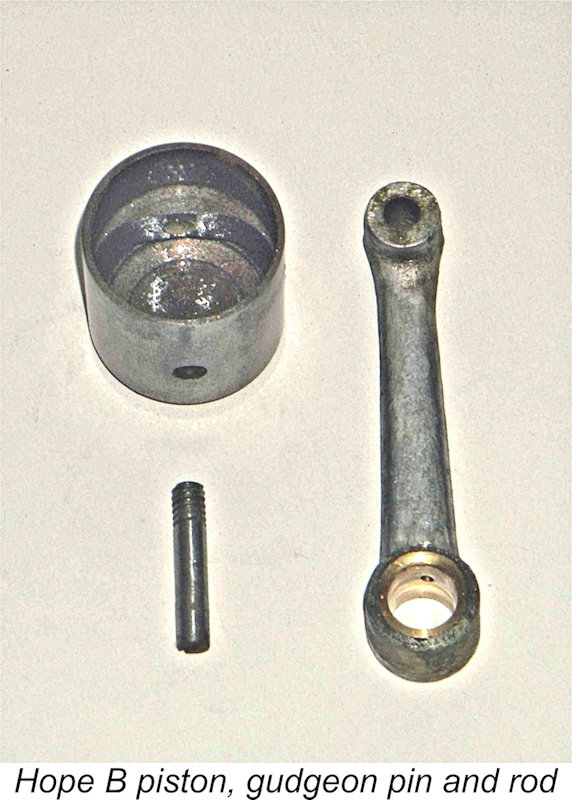
 example with the broken rod had been assembled with the gudgeon pin inserted from the front, and the exposed thread at the rear of the pin had really chewed up part of the small end bearing. It was simply a question of which end failed first!
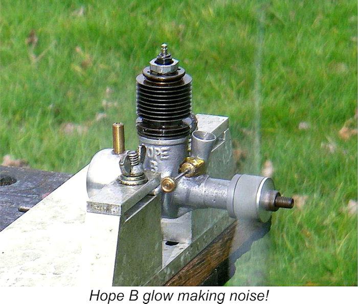 Once you get some fuel into it, the engine starts and runs very well indeed as long as you give it a healthy prime - very noisy too (my fellow
 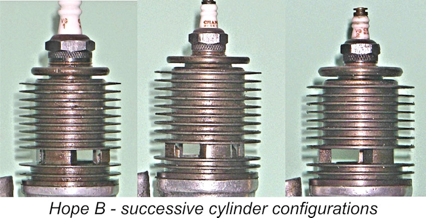 This change seems to have taken place after the switch from the
 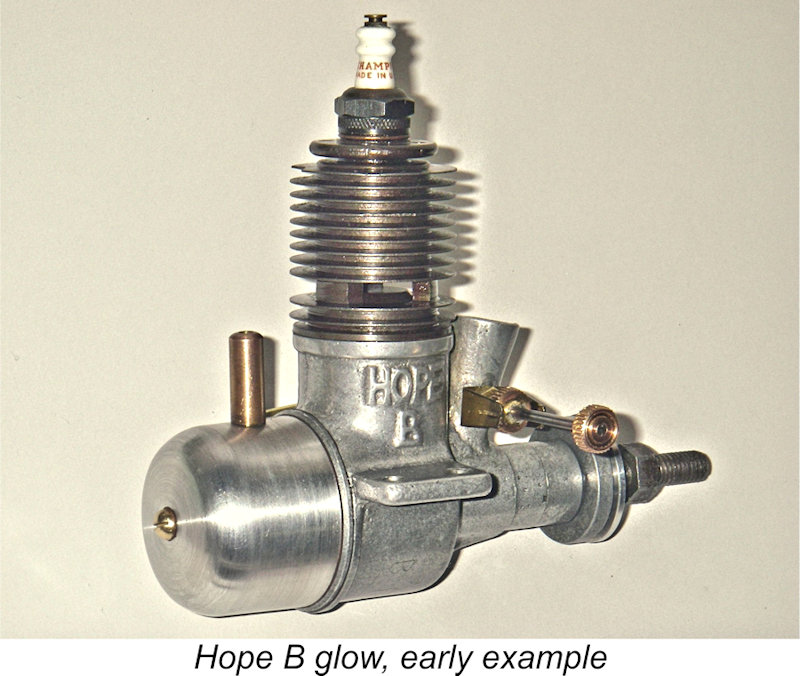 Alan was the first to admit that the above categories are at best broadly representative and that other variants undoubtedly exist. Mike Clanford's book, for example, shows a Hope B with a plastic tank. This may or may not be original, of course. Furthermore, one of my own engines appears to be of Alan's Type 5 above as far as the un-machined crankcase front goes but retains the Type 4 square-on-crankshaft prop driver mounting and disc-type prop driver along with a 6 mm crank thread. Another of my examples appears to be of Alan's Type 4 but has a ¼-32 plug thread, while the machined and grooved area at the front of the main bearing is integral with the case as opposed to being a separate alloy sleeve. This one also has the 8-fin high-compression cylinder. The third example in my possession is of Alan's Type 4 in all respects. And so it doubtless goes ...
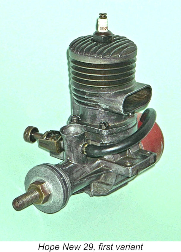
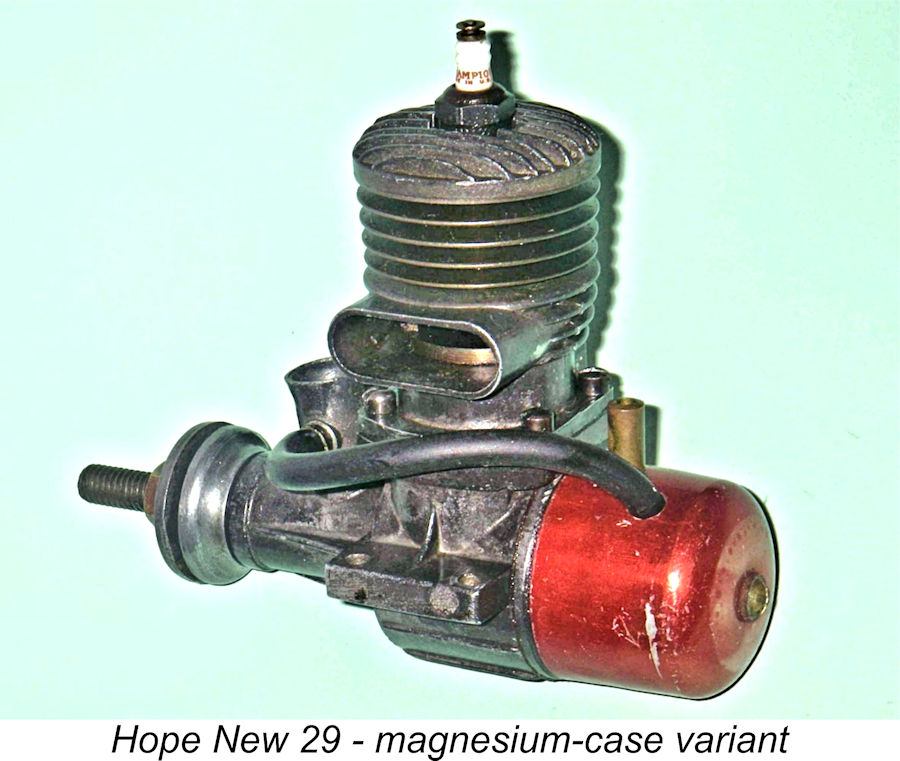 Hope Engineering were obviously in an experimenting mood at this time! Apart from changing their production methods and completely revising the design of their 29 model, they also indulged in what seems to have been a very short-lived flirtation with the use of a casting alloy having a significant magnesium content. My sole example of the first version of the New 29 features magnesium alloy castings throughout (confirmed by qualitative analysis of a small sample of scraped-off flash material). Even the connecting rod is cast from this material. In consequence, this example has the usual dark and somewhat "patchy" appearance of magnesium castings as opposed to the bright aluminium items used both before and after the brief appearance of this very rare model. It also has a marked tendency to develop that whitish powder so beloved of all Mills owners!
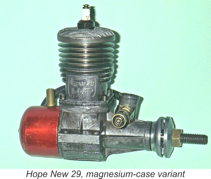 Another visible change was the elimination of the one-piece main casting in favour of a two-piece crankcase unit that was horizontally split below the upper bypass passage and exhaust stack. The New 29 retained the cast screw-in backplate and back tank that had been used on the previous Hope models, although the tank was now anodized red, again like that of the concurrently-revised Hope 19. The needle valve assembly too was very similar, although the needle itself was more compact and the Hope B's brass fuel line was abandoned in favour of flexible tubing. Presumably such tubing was readily available in Japan by this time.
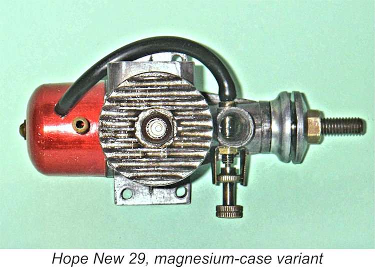
 was provided which incorporated the exhaust stack and upper bypass passage. This casting featured a matching flange at its base which was secured to the lower casting by four slot-head screws. As seen in the accompanying image, the generously-proportioned bypass passage was split by a cast-in partition running up the middle, presumably to improve side support for the lower cylinder.
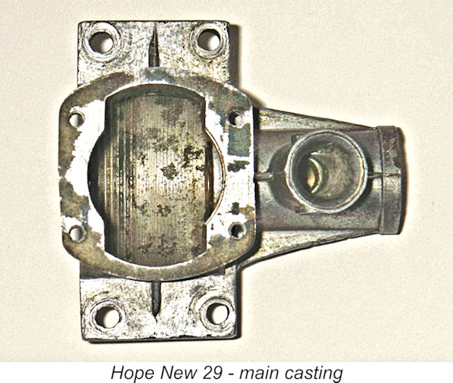 At first glance, it's a bit of a puzzle why the makers would utilize the relatively complex split casting described above. The answer is to be found when the engine is dismantled. The lower crankcase casting is laterally symmetrical, thus incorporating provision for the bypass (and hence the exhaust stack) to be placed on either side of the engine. As far as is known, all these engines were supplied from the factory with the stack on the left (facing forward), but all that was required to make the switch was to remove the four assembly screws followed by the cylinder assembly, reverse the piston to bring the baffle to the opposite side and then replace the upper cylinder unit in the reverse orientation.
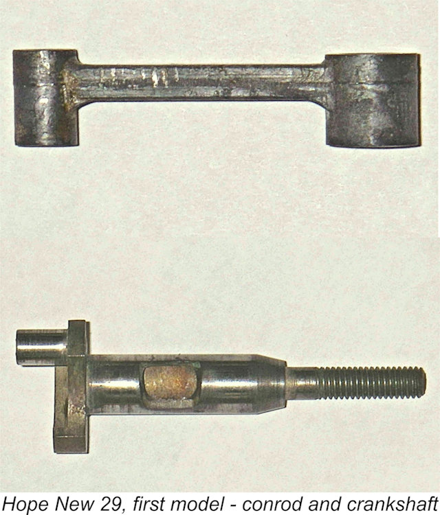
 There was also the fact that magnesium alloys are notoriously prone to want to return to their elemental state in the form of that aggravating white powder which all careless Mills owners know and love! There were thus a few good reasons for Hope to decide to switch back to the far less problematic aluminium. They appear to have done this after only a few examples of the magnesium-case New 29 were produced. It seems probable that this change took place later in 1950.
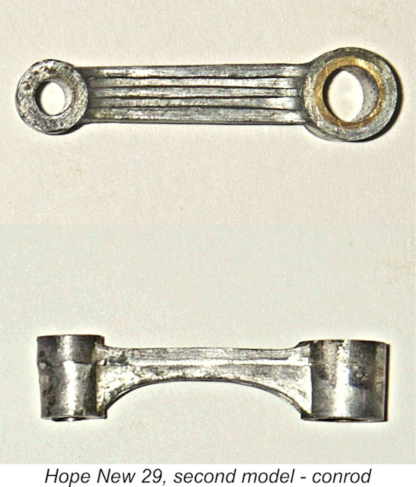 The revised con-rod was die-cast in aluminium alloy and was a far sturdier component than its predecessor. It was heavily ribbed and was made as thick and sturdy as case and counterbalance clearances allowed it to be. Furthermore, the bronze bushing at the big end had now returned. Overall, the revised rod was a far more substantial component than its immediate ancestor.
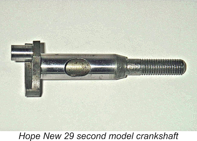 "slot" for communication with the internal passage. This removed less material from the shaft while also leaving no sharp edges to act as stress raisers. The basic form of the revised port is oval, which avoids sharp corners yet gives relatively rapid opening and closing when allied with the round induction port in the bronze-bushed main bearing. As a side benefit, the revised design also eliminated one production step.
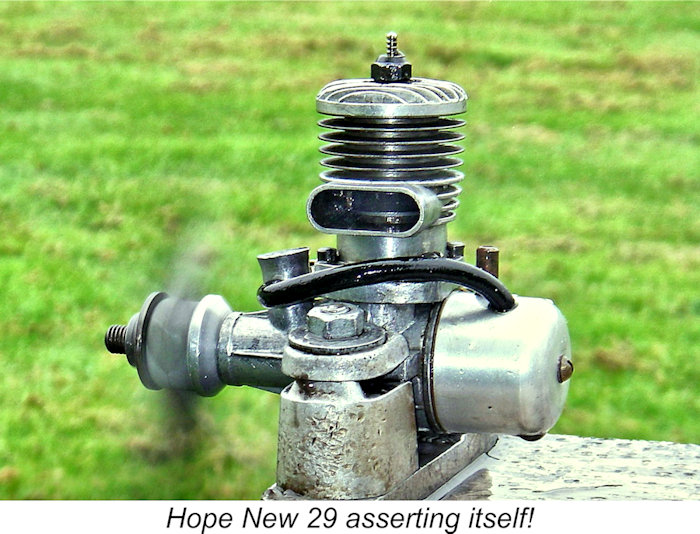 In all other respects, the revised design was identical to its predecessor. Weight was unchanged at 6¾ ounces all inclusive, and the bore and stroke too were unaltered. In addition, the engines continued to be every bit as well fitted as their predecessors. My examples of the engine start easily and run very well.
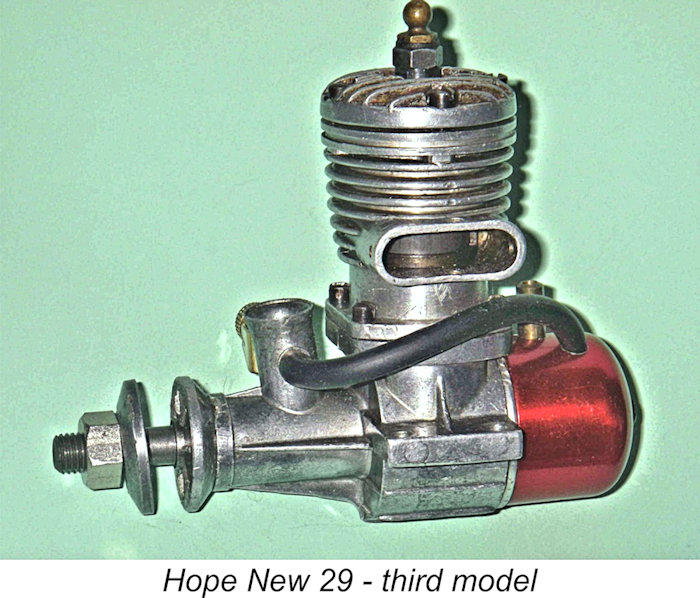 The practical result of deliberations of this nature was the introduction of a further significantly revised model of the New 29. As always with the Hope range, it's impossible to be definite regarding the date of this event, but a date of mid to late 1952 appears most likely. This impression is reinforced by the fact that the updated version of the New 29 to be described here is far less common than the previous model, implying a significantly shorter production period.
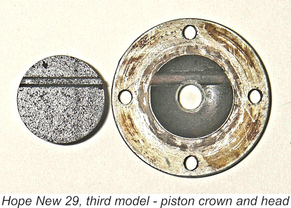 A separate cast alloy cylinder head was now used, being attached to the revised upper casting by four short screws in the conventional manner. The underside of this head was given a hemispherical contour with a slot for the piston baffle, theoretically at least resulting in a more efficient combustion chamber. By "feel", the compression ratio of this model was slightly higher as well.
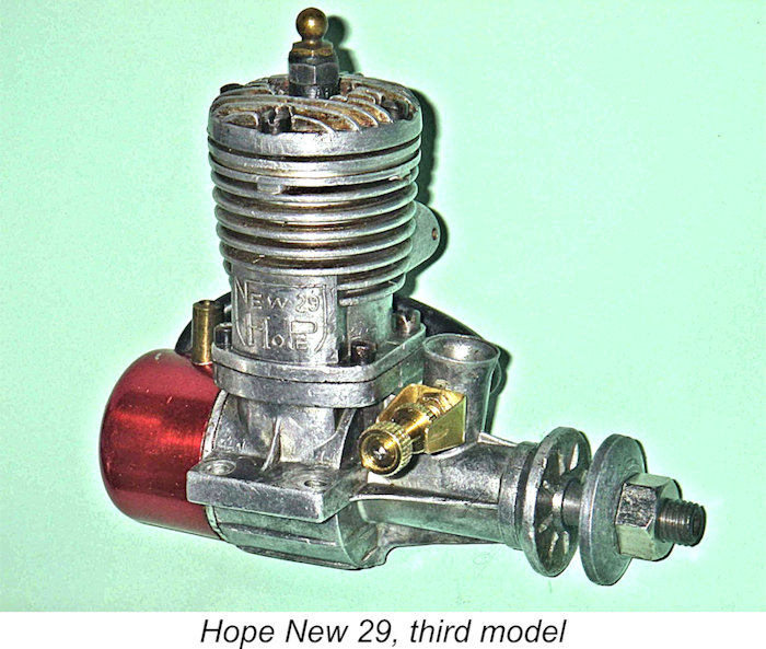 Measured bore and stroke of this version remained unchanged at 18.5 mm and 18.0 mm respectively for an identical displacement of 4.84 cc (.295 cuin.). The weight too was unchanged at 6¾ ounces with tank.
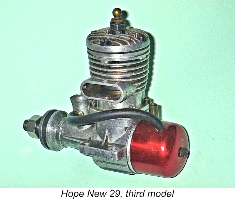 Based on the bench performances of the illustrated examples, the third variant of the New 29 did show a modest performance improvement over its predecessors, particularly at the top end. However, the revised model still lacked any appreciable edge over the rival models from Enya, O.S. and Fuji. Consequently, this version of the New 29 was in production for a relatively short time - almost certainly less than a year. It is far less commonly encountered today than the second New 29 model which preceded it. As usual, I have yet to encounter an example of this engine with a serial number, so there is no way of estimating production figures.
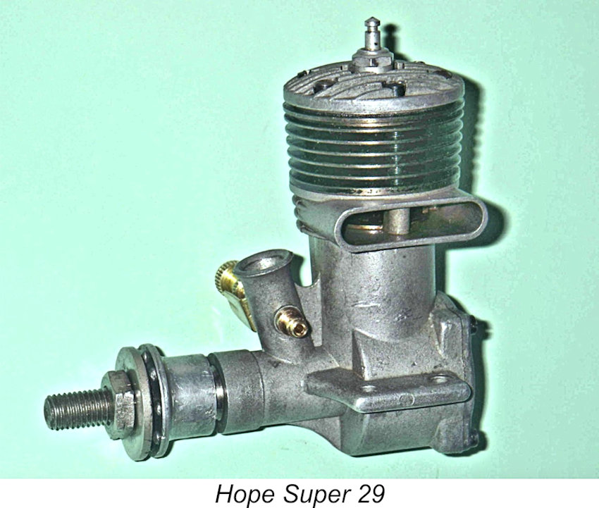 It seems logical to suppose that the development of the next Hope 29 model commenced in early to mid-1953 and that the resulting new model, designated the Hope Super 29, was introduced later in 1953. Indeed, this is the year given by Clanford in his previously-mentioned A-Z book. At present I see no persuasive basis for disputing this date.
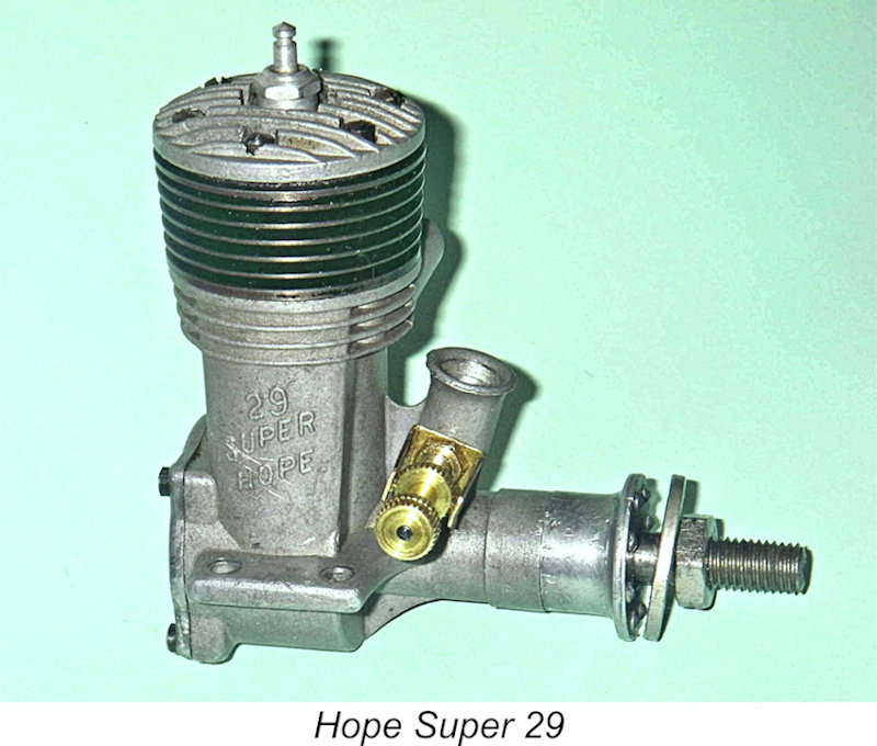 The new cylinder was made from steel as opposed to the former cast iron. This component was back to being a one-piece unit having integrally-turned cooling fins. Both the cylinder and fins were machined to minimal wall thicknesses.
 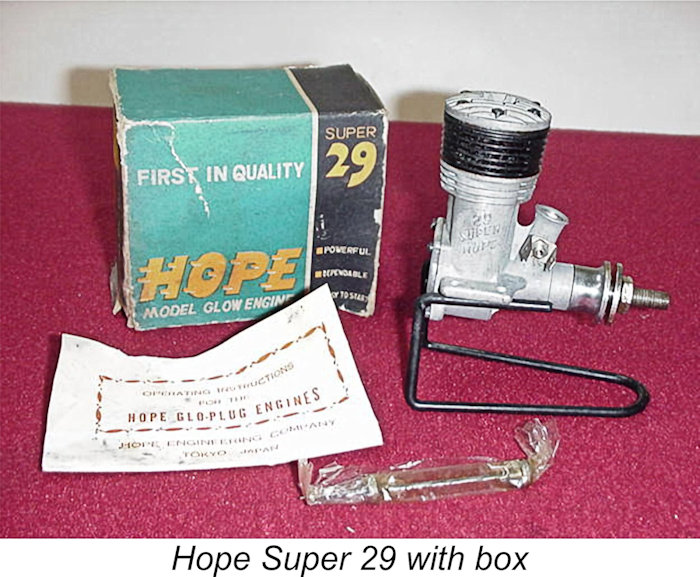 The Super 29 models were supplied in a two-tone blue box which now replaced the earlier red-and-yellow box. The contents were clearly identified on the boxes as being examples of the Hope "Super" series. Interestingly enough, the Hope Super 29 was also identified as such in relief on the die-cast crankcase. This was in contrast to the companion Super 19 model, which was only identified as such on the box.
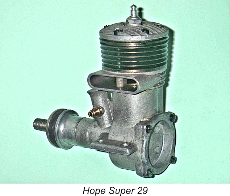 This worthy had managed to work his mischief with only minor marring of the screw heads, which was a blessing. However, he had managed to lose one of the small 2.5 x 0.45 mm head screws as well as the original needle. Fortunately, these items were easily replicated.
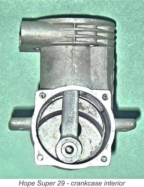 Anyway, the engine had to come apart for a complete re-build. Not a desirable step for the reasons explained earlier, but the saving grace was the fact that the engine appeared unrun. Even so, re-assembly required great care. The trick was to tighten the three long hold-down screws very evenly and progressively in extremely small increments, keeping pace with the three short screws to minimize distortion of the head and maximize the stiffness of the combined upper cylinder assembly. I also put the engine through a 250 degree heat cycle in the oven prior to the final round of tightening. Even so, there is some barely detectable evidence of microscopic distortion, which a little running would doubtless accommodate.
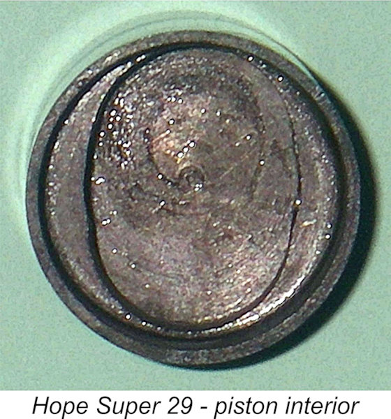 compression ratio is a comparatively modest 6.5 to 1, which should result in relatively low conrod stresses. Moreover, these engines reportedly do run well with no problems, so the rod must be up to the job. Somewhat oddly, the big end bushing has once again disappeared, as it did on the early version of the Hope New 29.
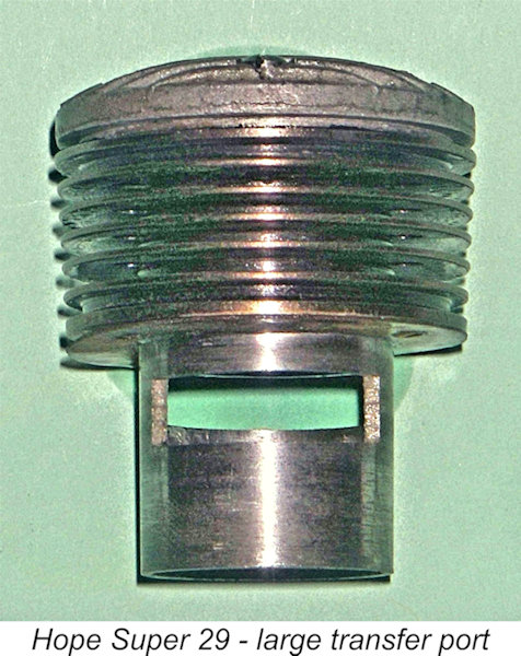 The cylinder is notable for the impressive size of the transfer port. The 10.5 mm diameter crankshaft has a rectangular induction register port with a generous 8 mm diameter internal gas passage. When coupled with the 180 degree induction period provided (35 degrees past bottom dead centre to 35 degrees past top dead centre), this should be a very free-breathing engine indeed!
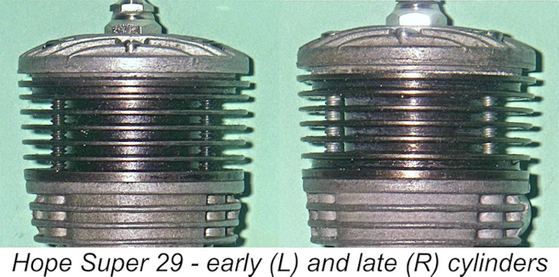
 stresses imposed by the three main hold-down screws. A later date for this example is strongly implied by this factor. In all other respects, the engineering design appears unaltered.
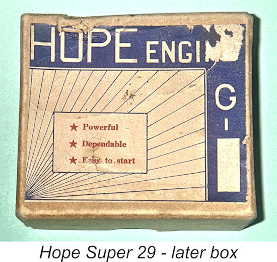 The item that is most different is actually the box, which is of a style that is entirely new to me personally. Inquiries directed to my Japanese informants yielded the comment that this box style was used for the very last engines sold. It appears that a point was reached at which the decision was taken to suspend production and simply sell off engines and parts already on hand. However, the company had run out of the rather fancy "Super" boxes mentioned earlier. Since there were no plans for continued production, there was no point in going to the expense of ordering a further run of these boxes.
| |