
|
|
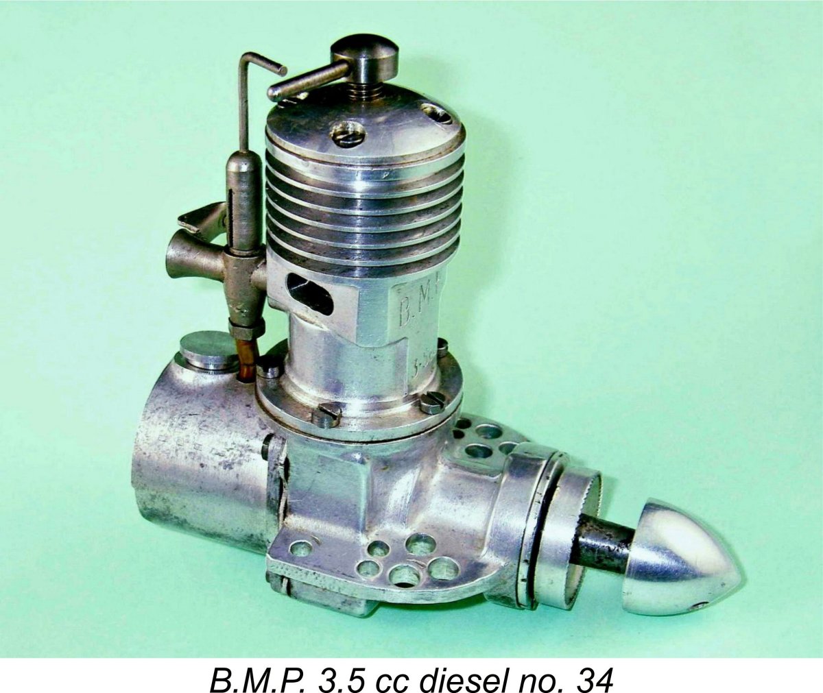
Bournemouth Beauty - the B.M.P. 3.5 cc diesel
My earlier article to which reference was made appeared in January 2012 on the late Ron Chernich’s “Model Engine News” (MEN) website, where it may still be found. It included a great deal of information about the designer of the engine, Henri Baigent (1909 – 1971), who was one of England’s true masters of the modelling craft. Despite his Continental-sounding name, Baigent was actually as English as treacle pudding! He was born in Dagenham, Essex as Henry (sic) Cyril Baigent. His family name stemmed from the fact that his father was descended from a Huguenot family which had come to England around the middle of the 17th century to escape religious persecution in France. The rendition of his first name as Henri originated with some of his fellow modellers after WW2 when he was over 36 years old. Given the existence of the earlier article, why have I gone to the trouble of writing this second text? Well, at the time when the original article was written I did not follow my usual practise of undertaking a full performance test of the engine. I can’t recall the reasons for this omission – probably time pressures - but the fact remains that the earlier article did not include any performance information. This is a significant omission which the present article will address. In addition, a certain amount of new technical information has since come to light, including details of a few more examples as well as some additional serial numbers. Since MEN became frozen upon the untimely death of my greatly-missed mate Ron Chernich, the creation of a new article on this site is the only way of updating any of my earlier work. That said, the original article remains well worth reading, since its scope is considerably broader than that of the present text. Here I will focus more or less exclusively upon the B.M.P. 3.5 cc diesel. Finally, my greatly-missed mate Ron left us in early 2014 without passing on the access codes to his heavily encrypted site. Consequently, no maintenance of that site has since been possible, making it inevitable that a slow but inexorable deterioration is taking place over time. It’s this issue that has led me to transfer a number of what I consider to be my more important articles over to my own site. This is one of them.
Although he became best known for his outstanding scale model cars, Baigent was also responsible for a number of model engine designs, including both 0.9 cc and 3.5 cc B.M.P. diesels as well as the very rare E.R.E. 2.48 cc diesel, of which much more elsewhere on this website. Readers who are interested in learning more about Baigent’s remarkable career are referred both to my earlier article and to Ray Baigent’s website – I will not repeat most of that information here. The present article will focus on an evaluation and test of the B.M.P. 3.5 cc model together with a historical summary of the B.M.P. marque. It’s to the background of that story that I will now turn. Genesis of the B.M.P. Diesels
Henry thus emerged from the wartime period at age 36 as a highly skilled and experienced precision engineer. His early post-war involvement with model aero engines stemmed from the fact that by late 1945, immediately after the conclusion of hostilities, his only son Raymond (always known as Ray) had developed a strong interest in aeromodelling. Now that he had more free time in which to do so, Henry began to take an interest in the technical side of his son’s hobby, initially through the provision of advice and support. His precision engineering background naturally led him to take a particularly close interest in model aero engines. At this point, it’s necessary to place our story in context by taking a moment to revisit the period during which Henry’s interest in models first became stimulated. Although there had been a growing power modelling movement in Britain prior to WW2, with a number of British model engine manufacturers challenging the marketplace during the 1930’s, the outbreak of war had the immediate effect of diverting model engine manufacturing facilities into war-related production. Indeed, the flying of I/C-powered model aircraft was prohibited by law in Britain during most of the wartime period, a constraint which was only finally relaxed in September 1944. As a result, model engines were in extremely short supply in early post-war Britain. As of late 1945, commercial model engine manufacture in the country had yet to resume. Such new engines as did become available during this early post-war period were mostly individually imported through contacts in the United States and Europe, or were individually home-constructed by talented model engineers working in their spare time. Everyone else had to use pre-war products which had survived the war. Naturally, those did not include any diesels.
Accordingly, any British modeller requiring a diesel engine as of early to mid 1946 was on his own. If you wanted such an engine and couldn’t somehow obtain one of the Continental or American models which were then in production, you either had to make it yourself or get some talented friend or relative to do so for you. Young Ray Baigent was in this very position as 1946 rolled around, making it inevitable that he would turn to his mechanically-skilled father for help. Naturally, the design and construction of a model aero engine presented a challenge which resonated very strongly with Henry’s mechanical leanings. He was more than willing to promise that he would indeed make an engine for Ray. This commitment proved to be the seed from which the B.M.P. venture was destined to grow.
This one-off unit had a total displacement of around 10 cc. Initially it did not work, but Henry steadfastly pursued solutions to its various problems, finally resolving all of the difficulties by mid-1946. Ray recalled the general excitement within the family when the engine was first successfully run! This remarkable engine was later converted to glow-plug and then spark ignition, being used in a series of Henry’s outstanding model cars, as seen above. From his experience in developing this unique powerplant, Henry gained a great deal of insight into model diesel engine design and construction. In mid-1946, after sorting out all the problems with the 3-cylinder unit, he returned to his original mission of building a practical model aero engine for his son Ray to use in a model aircraft which he was then designing. For reasons which are unclear today, Henry decided upon a displacement of 3.5 cc – somewhat larger than ideal for young Ray’s purposes. It’s quite possible that the engine used a piston/cylinder configuration taken from the 10 cc triple, but we don’t know this for certain.
As stated earlier, this was the first British model diesel to use a twin ball-race shaft. Indeed, the only previous commercial British engine of which I'm aware to use such a shaft was A. E. Jones' 14.5 cc Atom Minor of 1934. Henry's prototypes proved to be extremely successful in operation by the standards of the day, to the extent that many of the local Bournemouth-area modellers immediately expressed a strong desire to own one themselves. This may seem surprising given the engine’s substantial bulk and weight as well as its somewhat offside displacement in the context of then-current competition categories. However, we must recall once more that at the time in question the first few commercial model diesels were only just beginning to appear on the British market. Hence if a model diesel appeared that would start and run dependably most of the time, modellers would snap it up regardless of its displacement. The general enthusiasm with which the prototype engine was greeted led Henry to approach a local precision engineering firm (name now lost) in the latter half of 1946 with the suggestion that this engine would be a commercial success if they produced it in quantity. The response to the prototype had evidently shown that the market was apparently wide open for a practical model diesel engine of this kind. It was around this time that members of the local model club began to render Henry’s name as Henri, pronouncing his full name in Continental style as “On-ree Bay-junt” with a soft "j". This apparently amused Henry no end, the result being that it became quite the usual thing to address him directly in this manner. Doubtless Henri (as we must now call him from this point onwards!) recognized that this rendering of his name imparted a considerable cachét, since it implied a Continental connection synonymous with such revered names as Bugatti, Maserati, Hugo Tanin and other iconic mechanical innovators of the day. However, it was quite a while before he traded officially by the name of Henri. B.M.P. production commences Henri’s approaches to the afore-mentioned precision engineering company fell on fertile ground, resulting in a joint decision being taken to produce Henri's new 3.5 cc diesel design in series. To carry out this program, a new company called Bijou Mechanical Productions (Bournemouth) Ltd. (or B.M.P. for short) was established, with the owners of the original engineering company and Henri himself as co-directors. The new company traded from an address in Bournemouth. It appears that the primary effect of the agreement was to make the engineering firm's existing production facilities and workforce available to Henri for his use in manufacturing the B.M.P. engines. In return, Henri brought the required expertise to a company which had the necessary production capability and the willingness to become involved with model engine manufacture, but not the required technical know-how. Henri's direct personal involvement with the model engine production was doubtless a condition of the agreement. The manufacturer's instruction sheet stated specifically that the engines were built "under the personal supervision of the designer". Consequently, the manufacture of the B.M.P. engines was very much a hands-on affair as far as Henri was concerned. Ray Baigent recalls that his father was personally very closely involved in all aspects of B.M.P. production, with Ray helping out as opportunity offered. All the casting work as well as the machining was carried out in-house. According to O. F. W. Fisher's 1977 book entitled “Collector’s Guide to Model Aero Engines”, the company began by making a small trial batch of B.M.P. 3.5 cc diesels, presumably to test the market through local distribution and field testing in advance of any national advertising. The evidence suggests that these engines were made in around September or October 1946. Fisher states that the engines in this initial batch were un-numbered. This initial un-numbered trial batch seems to have been very small - examples from this batch are very seldom encountered today, although my good mate Peter Valicek has one, just to prove that they do exist! However, the results of this exploratory stage were clearly sufficiently encouraging that the production of a second much larger batch of some 200 engines was soon underway along with the commencement of national advertising. The company began to apply serial numbers to the engines at this stage, numbering them sequentially from no. 1 upwards as they came off the line.
The advertised selling price of the engine was £8 9s 6d (£8.47 in modern money), a very significant investment in early post-war Britain when a man grossing £8 a week would have been considered to be relatively well off. It would be equivalent in spending power to around US$500.00 today. The same advertisement announced that a suitable matching airscrew was also available from B.M.P. at an extra cost of 8 shillings (40p). The timing of that initial “Aeromodeller” advertisement appears to confirm that the engine must have been in existence and available by November 1946 at the latest in order to both complete the engine's market testing and to allow time for the lay-out of the advertisement to meet the early December 1946 editorial deadline for the January 1947 issue. This in turn confirms the right of the B.M.P. 3.5 to be recognized as one of the earliest commercial diesels to enter the British marketplace, since it followed Britain’s first such products, the Mills 1.3 from Sheffield and the Owat 5 cc fixed-compression model from Bradford, by only some three months or so at most.
The high price of the B.M.P. was maintained for some time in the face of this competition – the engine was still being advertised by Henry J. Nicholls at the same price as of February 1948. Presumably this price was seen as being justified by the engine’s considerably larger displacement than most of its contemporaries as well as its technological sophistication with the twin ball races. However, it’s clear that the engine’s high price must have contributed significantly to its relatively short market tenure and relatively low production volume. The B.M.P. 0.9 cc Model
During the period when the B.M.P. 3.5 cc model was being developed into its production form, Henri’s son Ray had become interested in the relatively new sport of control-line flying and wished to build a C/L model to be powered by a far smaller diesel engine. This led directly to the development of the B.M.P. 0.9 cc diesel, for which young Ray was largely responsible (at Henri’s insistence!). In many ways, this engine followed the design pattern of its larger brother apart from the use of radial mounting as opposed to beam. It was undoubtedly one of the first engines of its displacement worldwide to feature a twin ball-race crankshaft – indeed, there have been few such engines since. The prototype used crankshaft rotary valve induction with a plain bearing shaft, but the production version reverted to the side-port pattern and twin ball races of its larger sibling. It was reportedly an excellent performer but was never produced in significant quantities. The sole advertisement for this engine that I can find was a second placement by J. W. Kenworthy which appeared in the February 1947 issue of “Aeromodeller”. This advertisement focused on the B.M.P. 3.5 but also stated that “production of the B.M.P. 0.9 will commence shortly” and invited orders. The projected selling price for this model was quoted as £5.
Despite its worthy qualities, it would appear that very few examples of the B.M.P 0.9 cc model ended up being made, since these units are definitely about as rare as they get today. There are hen's teeth, rocking horse droppings - and the B.M.P. 0.9, the latter being perhaps just a bit more difficult to find than the others! I've never so much as had a personal encounter with anyone who has ever owned an example! But they do exist.......... One can see the family resemblance in several features, notably the exhaust porting, the cylinder attachment system and the use of twin ball races. Production History of the B.M.P. 3.5
It would thus appear that a second numbered batch starting at engine no. 201 was in fact produced. There’s no way of knowing how many engines were included in that second batch, but the seeming scarcity of surviving examples suggests that it was not large – perhaps only 100 examples or so. We need to find a few engines with higher serial numbers to sort this question out. Any offers out there?!? It’s actually possible that falling demand led to the later engines being individually built to order rather than being manufactured in a batch of specific size. If so, they would have been numbered sequentially as they were completed over a period of time. I personally consider it to be highly unlikely that the total number of these engines produced exceeded 300 units. If anyone can authenticate a few serial numbers that prove me wrong, let's hear from you!
A certain amount of work was put into the further development of the B.M.P. 3.5. My own example number 131 shows unmistakable evidence of this – it has carefully measured bore and stroke measurements which combine to yield a displacement of 3.84 cc (0.234 cuin.). It also has a considerably reduced blow-down period due to the transfer port being located significantly further up the bore relative to the exhaust apertures. These changes may represent an attempt to improve the engine’s rather problematic power-to-weight ratio by increasing its power output without increasing its weight. The company actually went even further than this by producing a single prototype of a 5 cc version of the same basic design, apparently using the standard 3.5 cc crankcase and bottom end components with a one-piece upper cylinder having integrally-formed cooling This prototype evidently performed well. It was used successfully by Col. C. E. Bowden to achieve several record performances, most notably a world endurance record for model floatplanes established at Poole Harbour, Dorset. This engine still existed in working order at my initial time of writing (2011) in the possession of Ray Baigent. However, demand for the 3.5 cc model was steadily falling as a result of increasing competition from other manufacturers, and the 0.9 cc model had evidently failed to excite the marketplace in the first place. It was consequently becoming clear that the continuation of the B.M.P. enterprise was no longer economically viable. Accordingly, the business was wound up at some point during 1948, with the 5 cc model sadly never seeing production. The final national advertisement for the B.M.P. 3.5 cc diesel appeared in the March 1948 issue of "Aeromodeller". It actually appears very likely that manufacture of the B.M.P. engines actually ceased prior to the end of 1947. The primary evidence for this stems from the fact that the B.M.P. 3.5 cc model was specifically classified as being out of production in Appendix II of Ron Perhaps even more significantly, the B.M.P. engines were not included in Warring’s later table of data on the world’s documented model aero engines produced during the period 1948 - early 1951. This table was published in the April 1951 issue of “Model Aircraft” and was re-printed in Vic Smeed’s much later publication “Flying Models - Favourites of the Fifties” (Argus Books, 1988). A review of the engines which were included against those that weren’t makes it quite clear that other engines for which production is definitely known to have ceased prior to 1948 were intentionally omitted, strongly suggesting that the B.M.P. engines were among that number. The other factor which is consistent with a very short production run is the seemingly small number of present-day surviving examples as well as their generally low serial numbers. Even a one-year production period should have resulted in far more examples being manufactured than is suggested by the evidence. The number of survivors as well as the serial numbers reported to date seems to suggest that production figures were far smaller than we would expect from a production life of a year or more. The Aftermath – the E.R.E. 2.48 cc Model
However, the most tangible result of Henri’s ongoing model engine development work was a now extremely elusive 2.48 cc crankshaft front rotary valve (FRV) diesel engine called the E.R.E. (English Racing Engine - a clear poke at the full-sized E.R.A. racing cars!). After some successful tests, this engine was put into very limited production, achieving a number of competition successes in both car and aero applications. The E.R.E. story has been recounted in detail elsewhere on this website. Despite its seemingly worthy qualities, the E.R.E. never made it into series production, being constructed mainly to special order in even smaller quantities than the former B.M.P. 3.5. In any case, by now Henri’s interests were well and truly focused upon the world of scale car modelling, leading him to abandon the model engine field by the end of 1948. It is for his amazing achievements in relation to scale car modelling that he is best remembered today. But that’s another story that has been very ably told elsewhere by Ray Baigent. Henri Baigent died on April 13th 1971 at the age of 62 years following a series of strokes. The modelling world had lost one of its genuine masters. The B.M.P. 3.5 - Description
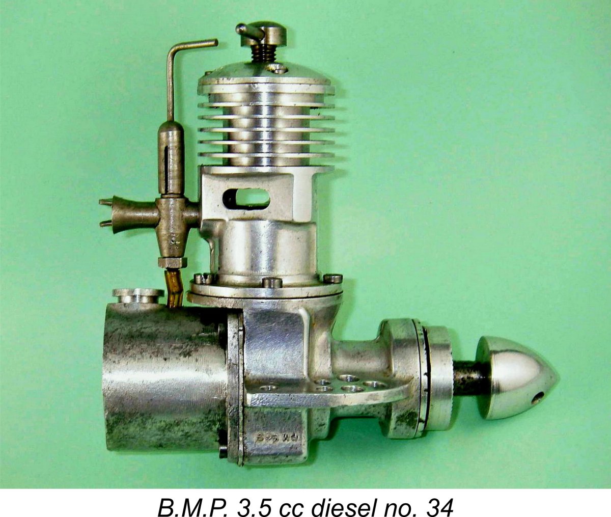
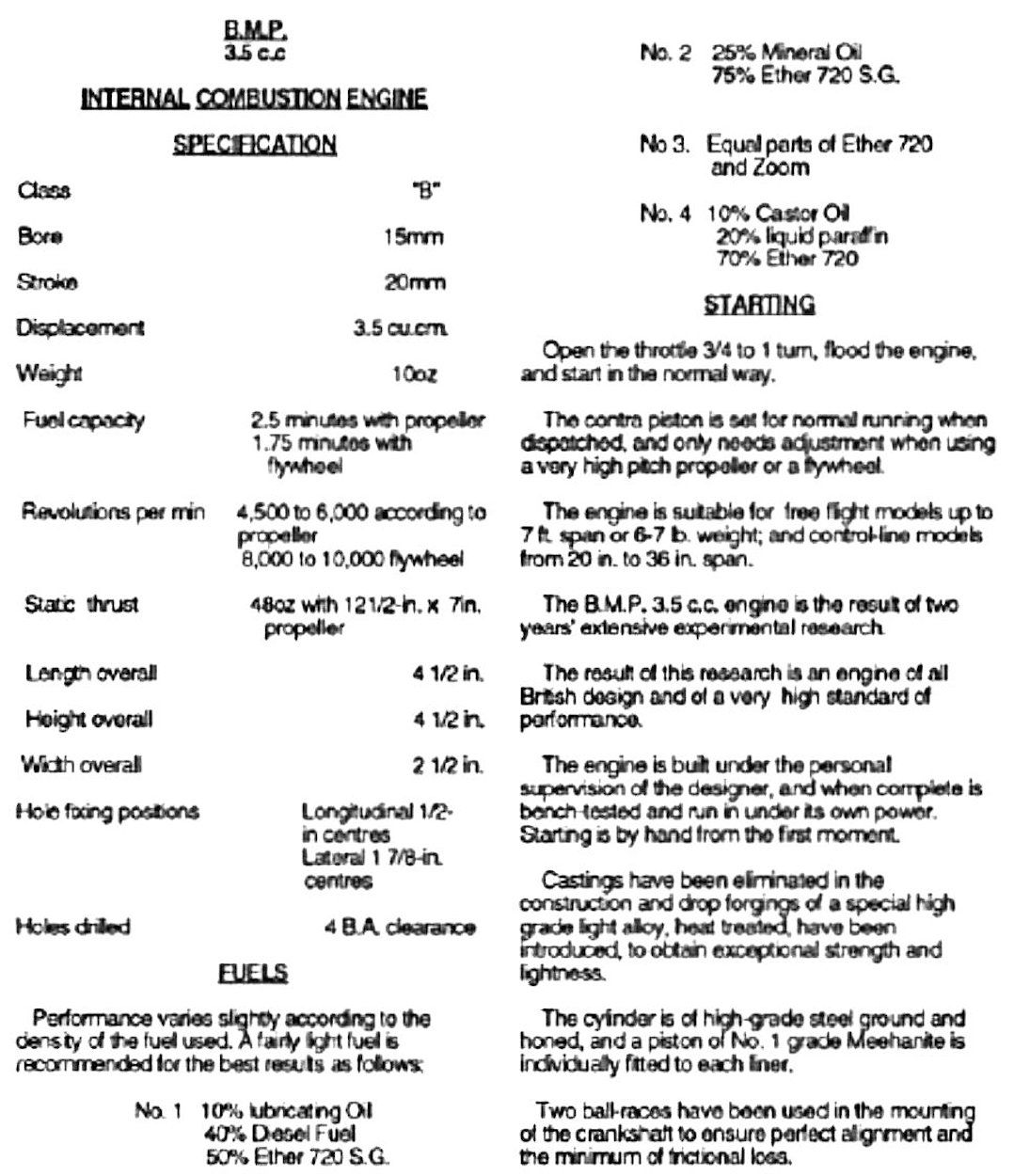
The manufacturer's specification sheet for this engine gives bore and stroke measurements of 15 mm and 20 mm respectively for a nominal displacement of 3.53 cc (0.216 cuin.). Measured bore and stroke of my lowest-numbered example of the engine (no. 34) are 0.590 in. (14.99 mm) x 0.785 in. (19.94 mm) for a calculated displacement of 3.52 cc (0.215 cuin.) – near enough to the engine’s nominal displacement of 3.5 cc. Engine no. 131 which is also in my possession is the previously-mentioned 3.84 cc example which has a repeatedly measured bore of 0.616 in. (15.65 mm) and a stroke ditto of 0.787 in. (19.99 mm) for a confirmed displacement of 3.84 cc (0.235 cuin.). It is this example which provides the direct evidence for some attempts at further development of the engine during its brief Interestingly enough, engine number 260 which I acquired subsequently reverts to the original dimensions exemplified by engine number 34, hence having a nominal displacement of 3.53 cc. The enlarged bore of number 131 may represent a short-lived experiment, perhaps testing the limits of the original design while pursuing the even larger displacement which was finally achieved in the aforementioned 5 cc prototype. The engine is a bit of a lump at all of 10.1 ounces (286 gm) including tank - heavier than some much larger engines. The addition of the four extra holes at the front of each of the very substantial engine bearers (which also doubled as webs for the main bearing) did little to improve this situation, serving merely to add some individuality to the engine's appearance! The motor is undeniably very sturdy, but the cost in terms of weight and bulk seems a little excessive.
My other examples bear the similarly-stamped serial numbers 131 and 260 in the same location. I have also been made aware of engines bearing the confirmed numbers 68, 105, 108 and 239. My present small sample of seven confirmed serial numbers thus goes from 34 up to 260, suggesting that fewer than 300 examples of the engine ended up being manufactured. If any reader is able to extend the serial number range in either direction, I'd love to hear from you! On all examples, another set of letters and figures appears on the crankcase below the right engine bearer (viewed from the rear). This series is cast in relief onto the crankcase in very small letters and reads PM 909 on all examples. It must be some kind of identifying mark for the casting rather than the specific engine. These letters are clearly visible in the right side views of the engine. Oddly enough, they are presented in an inverted orientation.
Mixture is transferred from the bypass into the cylinder by way of a single quite large transfer port cut through the steel cylinder liner at the front between the two exhaust apertures. This transfer port overlaps the exhaust port to a significant extent – even more so in the case of engine number 131 with its increased displacement and reduced blow-down period. Port areas are relatively generous and durations are unusually long for an engine of this type - clearly the makers were hoping for some reasonable operating speeds and were prepared to sacrifice a little low-end torque to get there. A flat-topped cast iron piston is employed. This drives the crankshaft through a nicely-made aluminium alloy con-rod which appears to be a forging. An unusual feature is the fact that the con-rod big end is attached to the shaft using a screw-in crankpin which threads into a tapped hole in the crankweb. The use of a screw-in crankpin was dictated by assembly considerations.
Subsequent investigation of engine no. 131 confirmed that it too featured a right-hand threaded crankpin. Moreover, at my request Peter Valicek checked the crankpin in his un-numbered example, finding that it too had a right-hand thread. With three out of three checked examples all having such pins, it appears to be a pretty safe bet that they all did! If anyone has an example with a left-hand threaded crankpin, let's hear from you!! If this assumption is correct, it would imply that the B.M.P. 3.5 was designed to operate in a clockwise direction viewed from the front. Although somewhat uncommon, this was by no means a unique design orientation at the time, when modellers appear to have been divided regarding the ideal operating direction of their engines. It is more than a little surprising to note that the manufacturers made no mention of this feature and its implications in their literature. In my view, they should have mentioned this issue regardless of the thread direction. Whether right or left, a screw-in crankpin pretty much dictates a specific operating direction if it is to be discouraged from unscrewing during operation. This direction should have been indicated very clearly. In the absence of any clarification of this issue, most users would assume that the engine should run in a counter-clockwise direction viewed from the front - I certainly did, to the great detriment of engine no. 260. Regardless of the design operating direction, the implications of the screw-in crankpin should have been made clear, particularly since this is a sideport engine which might be expected by its users to operate in either direction. Even if such clarification had been provided, the fact remains that the use of this design feature in a sideport diesel engine seems highly inappropriate given the marked tendency of such engines to backfire and run in reverse during starting. The obvious reason for its adoption in this instance is that the use of a one-piece shaft would have made it impossible to assemble the conrod onto the crankpin given the engine's crankcase configuration. However, clarification should have been provided, as it was in the case of the contemporary Mechanair sparkie, which also used a screw-in crankpin. The feature was more appropriate for a sparkie like the Mechanair, which can't start in reverse since the ignition timing doesn't permit this.
That said, it is true that once a setting is established, the B.M.P. will readily start and run on the same setting, so this is perhaps less of a problem than it might otherwise have been. Nonetheless, a cast-iron contra-piston gives a far better measure of control while the engine is running. Perhaps this was a somewhat futile weight-saving measure!? Although the engine's external appearance displays a few rough edges, the B.M.P. is very well made, especially where it counts. The crankcase appears to be a high-quality gravity die-casting. All fits are exceptionally good and the main castings are pleasingly polished. A nice touch is the fact that the engine bearers are milled on their undersides to ensure that they are both level and parallel, a refinement employed by ETA and others to help ensure a rigid mounting. Another classy feature is the provision of a cover plate over the front bearing to discourage the ingress of dirt. This is mounted just behind the prop driver and is held in place against the open end of the front bearing housing by three countersunk screws. It is clearly visible in the various photographs taken from the side or front. The very laudable intent was clearly to exclude grit from the bearing. International Model Aircraft (IMA) were to emulate this feature years later with their FROG 249 twin ball-race diesel, albeit with a non-metallic form of seal.
The thread on the top spigot for the needle’s split thimble is 7/32-40 Model Engineer – a very fine thread which should provide very precise mixture control while also promoting excellent needle stability. The lower fuel supply spigot is internally tapped 4 BA. A brass jet threads into this tapped hole to protrude some distance into the intake venturi. The open end of the tapped hole is closed by a hollow 4 BA hex-headed stud which has a brass fuel pickup tube soldered in place. All very complex, and an expensive assembly to manufacture. To add to the cost, the entire carburetor assembly appears to have been nickel plated following the brazing and soldering operations.
Following the initial publication of the original article on MEN, a reader kindly provided a photograph of B.M.P. 3.5 no. 68 which actually retained its delicate little shut-off flap. The flap plate has what appears to be a rubber ring screwed onto a stub to provide an air-tight seal. It was also noteworthy that the attachment is on the opposite side to my own engine, as is the fitting on engine no. 260 (which also retains its flap). The fuel tank is another heavily machined casting which is held in place by the same 4 screws which retain the crankcase backplate, thin paper gaskets being used to ensure a seal between the machined surfaces. The backplate thus doubles as the front wall of the fuel tank. The engine can readily be run without the tank - one simply removes the four screws, sets the tank aside and secures the backplate once more by re-installing the four screws. It would be necessary to adopt this approach in order to run the engine in anything other than an upright configuration. The fuel filler cap is interesting - it does not screw into its hole, but snaps in, being retained by the fact that its hollow spigot is split at four points on its circumference and has a small expansion of extra material surrounding its inner end. The splits allow this expansion to compress sufficiently to pass through the hole and then to spring open again to retain the cap in position.
It would appear that the “penny slot” comp screw is the most common variant and that the single-arm tommy bar version was possibly confined to the earlier examples. However, it would appear that the penny-slot arrangement may have come in for some criticism, because later engine no. 260 has a conventional two-armed T-shaped comp screw, as previously illustrated. There’s no doubt that the tommy bar components are far more convenient to use. The B.M.P. 3.5cc Diesel on Test I've owned B.M.P. 3.5 cc diesel no. 34 for many years now – I can’t even recall now where and from whom I acquired it! I do retain a hazy recollection of obtaining it in North America around 50 years ago during the period when no-one on that continent was interested in diesels or glow motors – they all wanted sparkers. I acquired a lot of rare diesels and glow-plug motors very cheaply during that period – I believe that the B.M.P. was one of these. There are some advantages to being old - you have had opportunities that are denied to others!
I recorded my experiences in the log-book that I've kept for decades in connection with all of my model engine running. My notes made at the time confirm that I had found the engine to be a fine starter and a smooth runner, albeit not very powerful. I specifically commented that it felt positively silky when turned over after a finger-choke - really nice! Fits were found to be generally beyond reproach, although this example has had a fair bit of long-ago use and there is some very slight play just starting to develop in the con-rod bearings. This is only detectable when the engine is completely "dry" after cleaning. I recorded the fact that the motor was dead easy to get going using standard procedures. However, the aluminum contra-piston meant that I had to be quick with the compression setting to get it right before the engine got too hot! This is in fact a chronic issue with engines having aluminium alloy contra pistons. If the Once a good compression setting was established for a given fuel and prop, I discovered that it could be left alone - the motor was found to start and run on the same prop at the same setting with no trouble at all either hot or cold. When cold, it took a little time to come up to a smooth-running state, but it invariably did so. In effect, I was able to treat it as a fixed-compression diesel at this point. This may be an explanation for the use of the very inconvenient “penny-slot” comp screw – it’s possible that adjustment of the compression setting was only anticipated between runs rather than during operation. With an aluminium alloy contra piston, that’s a very realistic expectation! The instruction leaflet reproduced below certainly suggests that this was the manufacturer's expectation.
A slightly cut-down 10x6 wood prop was found to be a good match for the engine. This is highly inconsistent with the maker’s recommendation of a 12½x6 prop as recorded by Ron Warring, but that’s what my long-ago notes say. There's an inconsistency here with my copy of the instruction leaflet (left), which actually cites a 12½x7 as developing the maximum static thrust. The 10x6 is equally inconsistent with the recommendations posted by Henry J. Nicholls in his February 1948 advertisement to which reference was made earlier. Nicholls recommended a 9x12 or 10x10 for control line applications, while a 12x8 or 11x8 were felt to be ideal for free flight use. One really odd feature of the attached factory instruction sheet is the comment that "castings have been eliminated in the construction". This comment is patently untrue - both the combined crankcase/main bearing unit and the tank are clearly based on castings. The inclusion of this patently-false comment is not readily explicable ............... Returning to my long-ago notes, I found that the engine seemed very happy in the 6,000—7,000 RPM speed range. Running was noted as being extremely smooth, although I did record the development of a not-inconsequential level of vibration. Generally speaking, I found the engine to be a well-made unit having an adequate performer for its era, type and displacement. However, I didn’t record any speeds with specific props, contenting myself with the general statement that the B.M.P.’s power-to-weight ratio appeared to be rather less than stellar despite its fine running qualities.
It took a while to re-create all of the missing parts very accurately using engine no. 34 as a guide, but the patient recovered well from its surgery, ending up as a nice-looking example as seen in the accompanying images. Compression seal was very much on the soft side due not to wear but to a couple of shallow scores in the bore, apparently due to the effects of a poorly-fitted wrist pin. However, I judged that there was enough there for starting and running, although power would doubtless be down a bit. All other fits appeared to be excellent. Now being in a position to conduct a full performance test on the engine, I made preparations to do just that. I brewed up a fuel containing 30% castor oil plus some 1½% ignition improver. Splitting the difference between Ron Warring’s recommended 12½ x6 prop and my own notes which favored a 10x6, I decided to begin with an APC 11x6 and see where things went from there. My next challenge became apparent from my initial attempt to mount the 11x6 prop on engine number 131. The engine's prop mounting thread is considerably too short for a prop having the hub thickness of the APC 11x6. A 10x6 is the thickest-hub prop that will mount, and even then there's really too little available thread for the standard aluminium alloy spinner nut. Thread life under test conditions with frequent prop changes would be minimal. I had to make a 1/4-26 BSF sleeve nut from mild steel to allow for mounting the 11x6.
Even so, the B.M.P. would run the tank out cleanly at the tested speed. Incidentally, the speed measured on that prop is slightly better than that achieved on the same prop by the 4.4 cc Kemp K4 diesel when tested a short time earlier for a previous article. It was readily apparent that engine no. 131 was game for a test despite its leaky piston fit. However, it could really do with a rebore in advance of any such test. This being the case, I decided that it was well worthy of a full restoration. Accordingly, I sent it down to my good mate Dean Clarke of Cre8tionworx Engineering in New Zealand for a complete overhaul to Dean's always-superb standard. Dean rebored the cylinder and made a new closely-fitted piston along with a new rod and wrist pin. He also replaced the potentially problematic aluminium contra piston with a cast iron component having a flat combustion face with a central dome to promote better combustion. Finally, he replaced the ball races since the ones already installed felt a bit "lumpy".
Upon its return home, the refurbished B.M.P. went straight into the test stand once more. When turned over with a prop fitted, the engine undoubtedly felt as if it had been set up a little on the tight side by Dean. Still, better tight than too loose!! My plan was to begin by giving it some running-in time using a 12x6 Zinger wood pusher prop operating in a clockwise direction viewed from the front. I quickly discovered one of the B.M.P.'s most endearing characteristics - easy starting. I've never succeeded in becoming really comfortable with starting model engines in a clockwise direction. My approach is to set the prop at "ten past eight" with the engine just coming up against compression in a clockwise direction, then flick the right-hand prop blade with a quick downward snap of the finger coupled with a bit of wrist action. The resulting flick is a little less forceful than my normal anti-clockwise efforts, but it generally suffices.
I followed through with my plan of keeping the engine running rich and under-compressed for the first 15 minutes or so. It was readily apparent that Dean had wisely set up the restored B.M.P. somewhat on the tight side and that a considerable amount of running-in would be required to release its best performance. Since I had no plans to fly this engine myself, I saw no point in expending the fuel and neighbourly-forbearance capital that would be require to complete the process. Accordingly I continued the break-in but finished each run with a brief period of fully leaned-out running for the purpose of gathering some data. The B.M.P. was found to turn the 12x6 Zinger test prop at 5,300 RPM - in the neighbourhood of 0.123 BHP at that speed. When fully leaned out, running was completely smooth and sag-free, although a certain level of vibration was apparent. In that condition, the engine ran the balance of the tank out cleanly.
This observation is completely consistent with the manufacturer's own data contained in the previously-reproduced instruction leaflet. In that document, the engine is said to be designed to operate at speeds between 4,500 and 6,000 RPM. My admittedly very limited data suggest that a fully run-in engine would likely develop around 0.140 BHP @ 5,800 RPM or thereabouts. The 12x6 airscrew appears to be perfectly matched to the engine's performance characteristics - again, an observation which is completely consistent with the manufacturer's recommendations. Summing up, I found the B.M.P. to be a well-made engine with excellent starting and handling characteristics and having the potential to deliver a long working life. It was also well able to swing a sizeable airscrew with more than sufficient vigor to fly a quite large free flight model. Its chief drawbacks were its bulk and weight for its rather modest power output, which would have told against it in a control-line application. Still, a quality product which was a very satisfactory unit to run! Conclusion I hope that you’ve enjoyed this summary of the history of one of the more intriguing and capable pioneer British model engine manufacturers of the early post-war period. The B.M.P. 3.5 cc diesel was a quality piece of merchandise and a very worthy initial commercial effort by Henri Baigent. Once again, our sincere thanks are due to Ray Baigent for so generously sharing his recollections of his father’s life and work. Check out Ray’s previously-linked website – fascinating! _______________________________________ Article © Adrian C. Duncan, Coquitlam, British Columbia, Canada First published on MEN January 2012 This revised edition published here December 2025
|
 In this article, I’ll take a second look at an engine which has already been the subject of one of my earlier efforts. This is the B.M.P. 3.5 cc diesel from Bournemouth in England. This relatively rare engine was the first British diesel to feature a twin ball-race crankshaft, giving it a place of some significance in British model engine history.
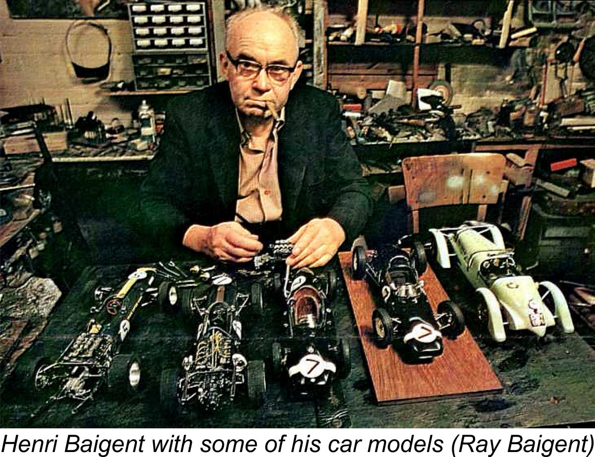 Before proceeding to the main subject of the present article, I must pay tribute to Henri Baigent’s only son Ray, who has done us all a great service by compiling information about his father’s life and work and presenting it on a most informative dedicated website. Ray’s
 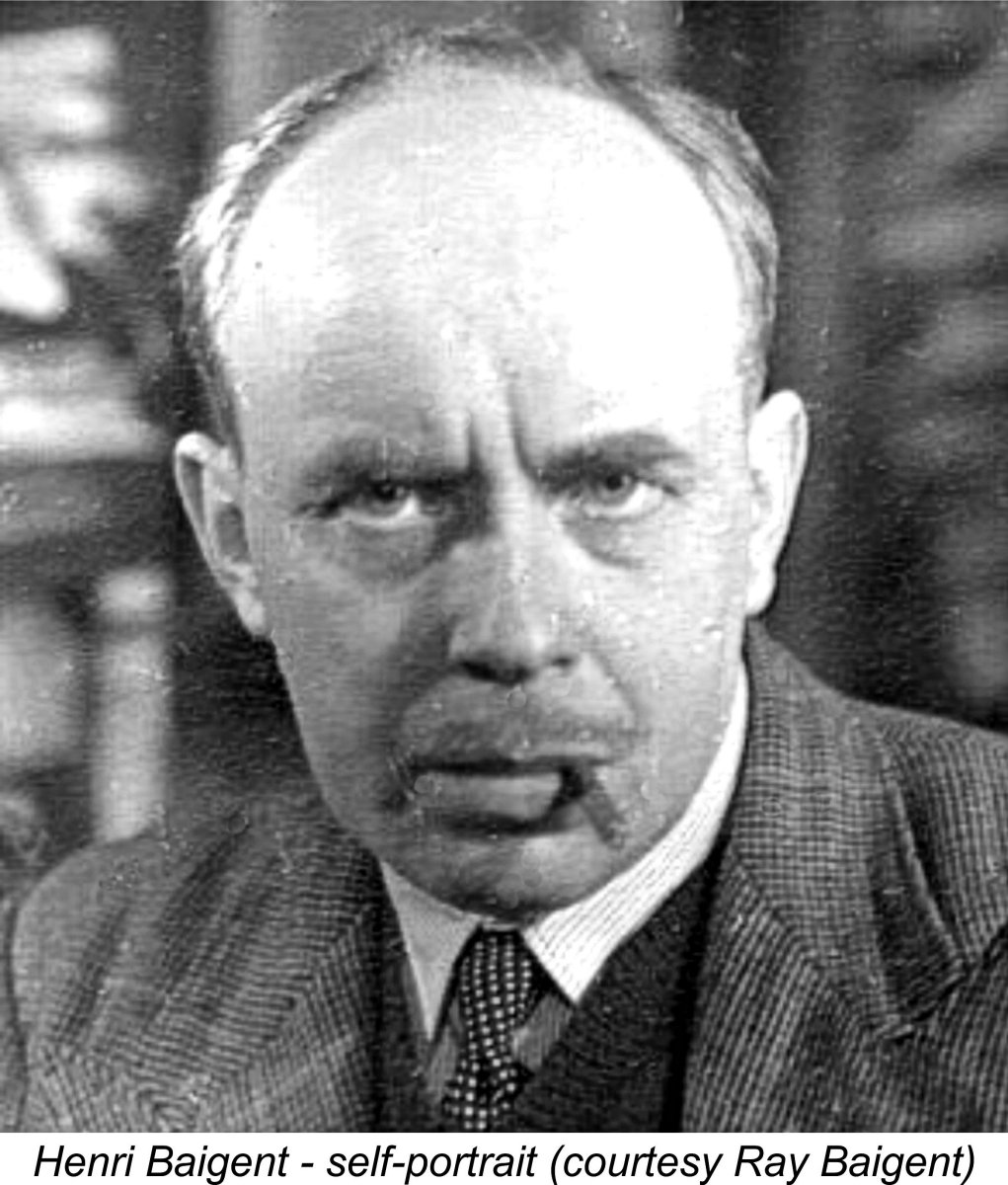 Henry Baigent (as he was still known then) had lived in Bournemouth since 1935. He had worked in the precision engineering field both before and during WW2, spending the wartime years in charge of an experimental workshop developing and making munitions for the war effort. This facility was entrusted with work of a very exacting nature, operating at a frantic pace. Henry’s reputation grew to the point at which he was frequently consulted to deal with difficult problems which other workshops had failed to resolve.
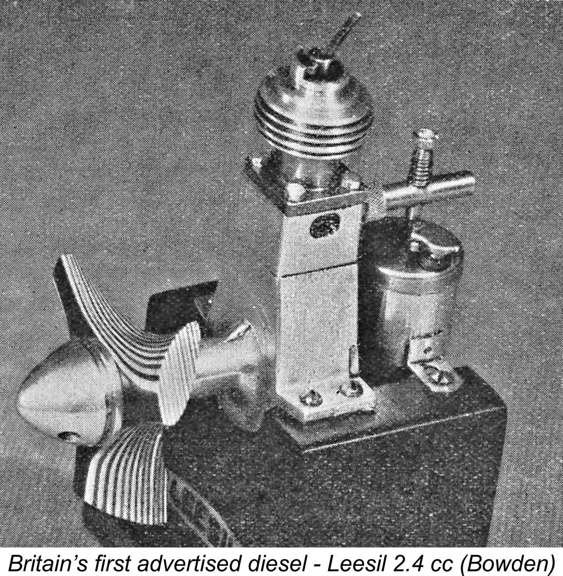 A number of British spark ignition motors did begin to appear in early 1946. These included the
 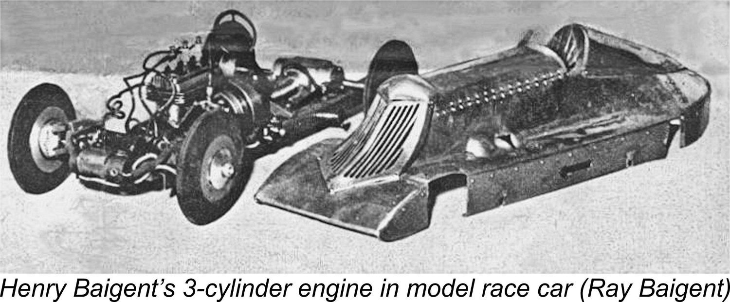 Henry immediately embarked upon the development of a suitable model diesel engine design, becoming increasingly engaged in his self-appointed task as time went by. As his understanding of his subject grew, so did his ambitions, the result being that this engine progressively expanded in scope until it became what must certainly have been the world’s first 3-cylinder in-line model diesel engine! Perhaps not exactly what young Ray needed to power his simple models, but there it was!
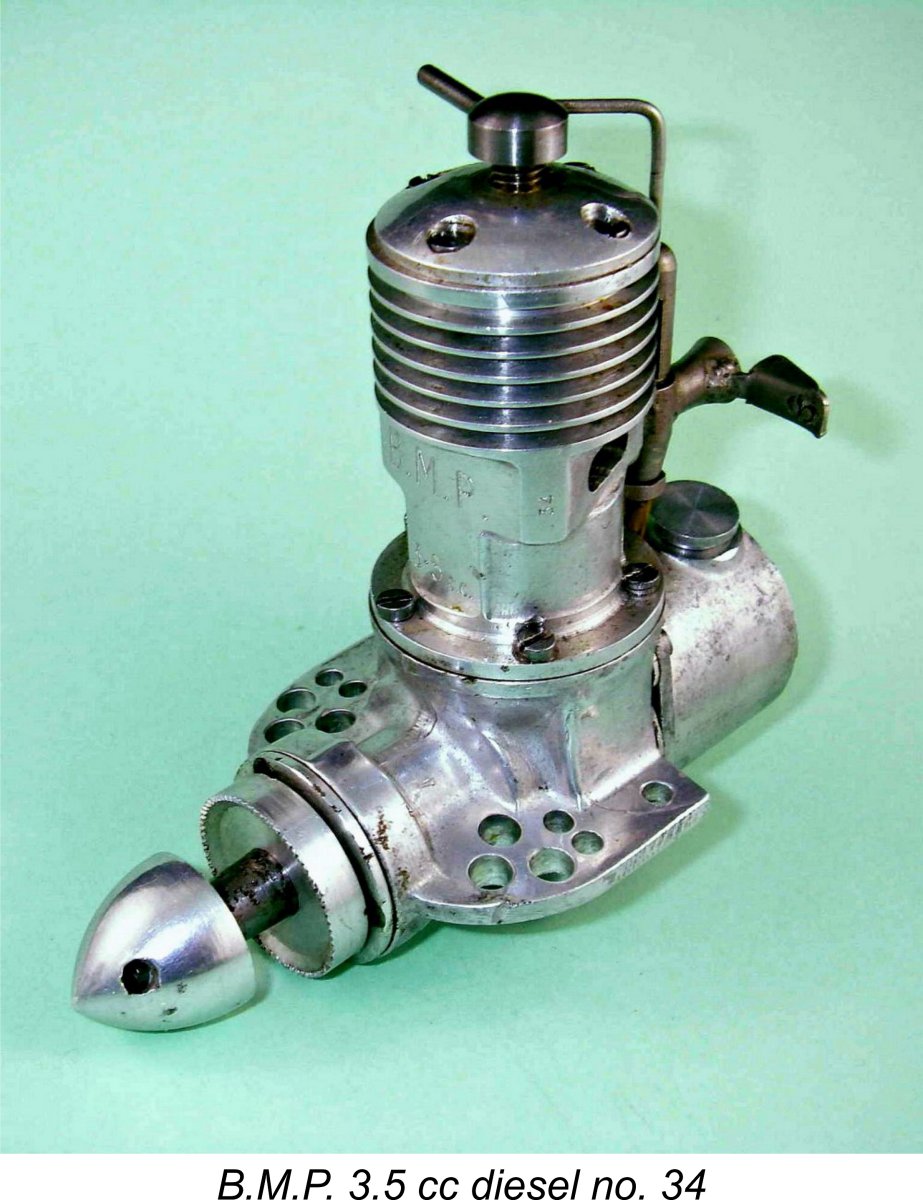 In any event, Ray recalls that the model design which he was then developing would have been both overpowered and overloaded by an engine of this displacement and weight. He therefore pressed his father for the development of a smaller engine, with results which we shall review in a subsequent section of this article. In the meantime, Henry persisted with his original design plan, developing a 3.5 cc single-cylinder diesel engine with a twin ball-race crankshaft. The resulting unit was of course none other than the prototype of the B.M.P. 3.5 cc diesel which is our main subject.
  The introductory national advertisement for the new engine appeared in the January 1947 issue of “Aeromodeller” magazine. This advertisement cited local Bournemouth model shop proprietor and former Wakefield Trophy winner (1933) J. W. “Joe” Kenworthy as the distributor of the B.M.P. engines. Kenworthy was a great supporter of the B.M.P. venture at the outset. However, the ongoing advertisements imply that by May 1947 national distribution had shifted to Henry J. Nicholls Ltd. of London.
 The high price which was attached to the B.M.P. 3.5 as well as other contemporary productions such as the 4.4 cc
 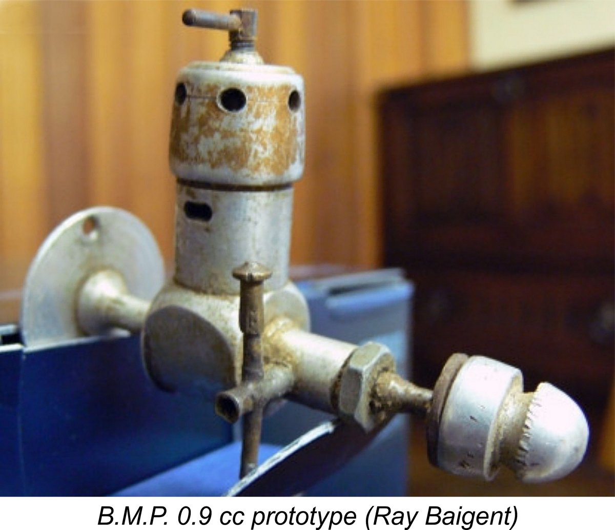 It soon became apparent that the choice of the 3.5 cc displacement had been a mistake in purely commercial terms. At the time, there was no competition class specifically for 3.5 cc engines in Britain, which had a considerably damping effect upon demand for the new product. Moreover, the physical bulk and weight of the engine told against it by comparison with some of the other designs which soon began to appear to challenge the B.M.P.
 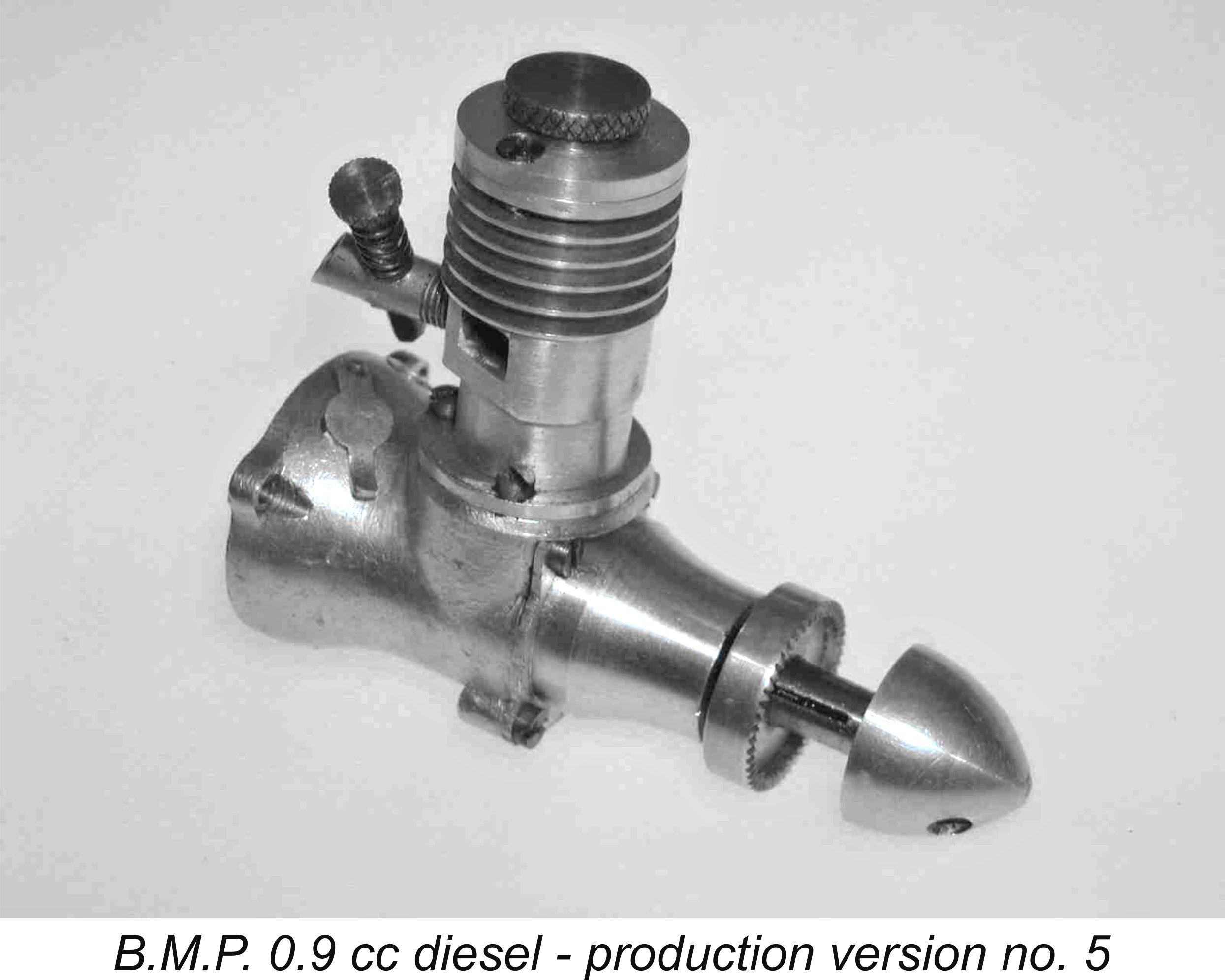 Despite the seeming absence of any further advertising, the B.M.P. 0.9 seems to have entered production on schedule and remained on the market for some time, since it was mentioned again in the May 1947 issue of “Aeromodeller" in an article entitled “British Diesel Summary” by Lawrence Sparey (writing as “Artifex”, pseudonyms being a commonly-employed device among technical writers at the time). One of its purchasers was the redoubtable Col. C. E. Bowden, who mentioned it in his June 1947 “Aeromodeller” article summarizing his experiences to date with diesel engines. Bowden reported having used the little B.M.P. with great success in a 45 in. span free flight cabin model called the “Meteorite”.
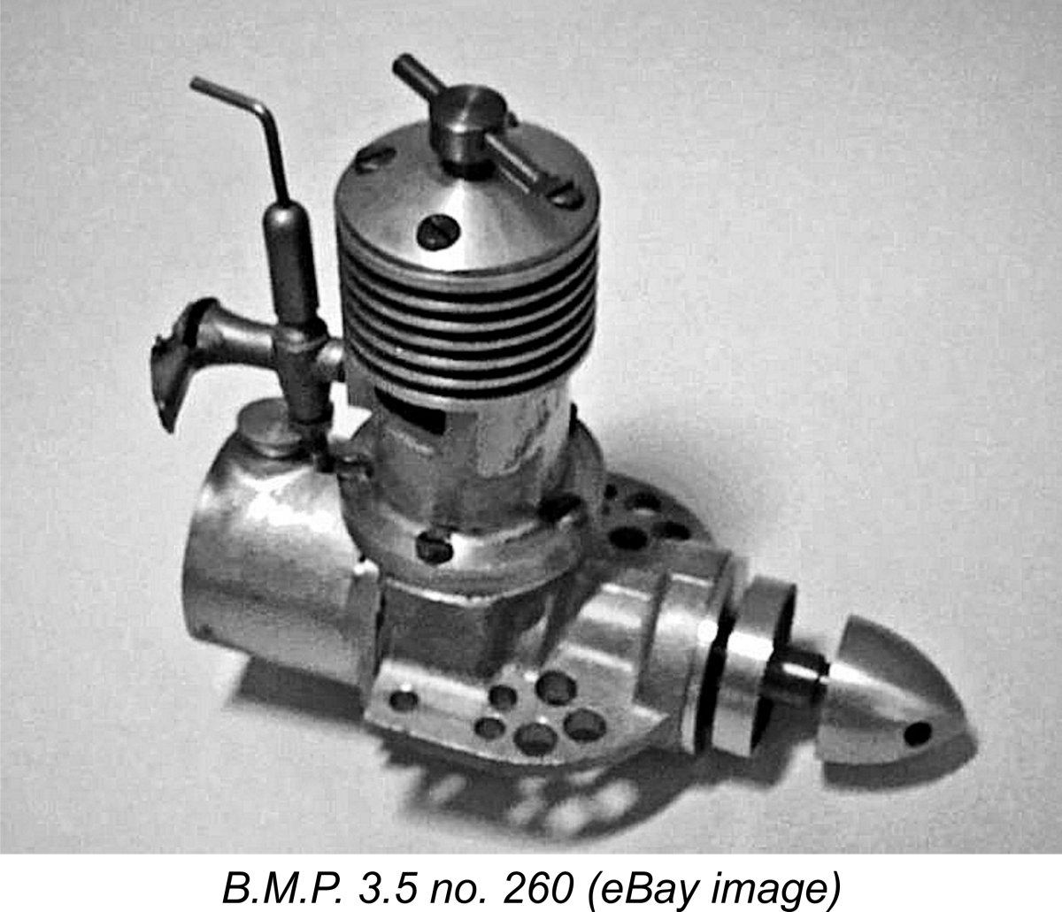 Following completion of my initial research into this engine in late 2011, I would have said that the first numbered run of some 200 engines which followed the un-numbered introductory batch in early 1947 was the only such batch manufactured. However, the subsequently-learned fact that my late and greatly-missed mate Paul Rossiter owned engine number 239 forced a revision of that view. My own even more recent acquisition of engine no. 260 on eBay provoided further confirmation as well as extending the known serial number sequence.
 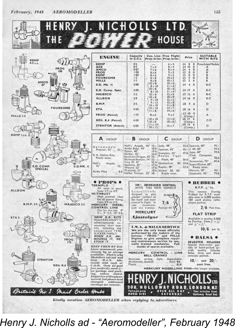 Whatever the true production figures, the B.M.P. 3.5 certainly did not remain long in production. Moreover, those that were produced seem to have been very slow sellers, likely on account of the higher-than-average price combined with the engine’s high weight and bulk for its power output. Henry J. Nicholls advertised the B.M.P. 3.5 sporadically during the period 1947-48, albeit seemingly with very limited sales success. Although as stated earlier Nicholls was still advertising the engine at its original price of £8 9s 6d (£8.47) in February 1948, the price of the engine was soon thereafter reduced to a still significant £6 10s 6d (£6.53). However, this was insufficient to prevent the engine from quietly fading from the scene as 1948 went on.
 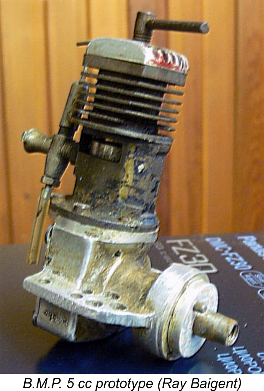 fins. This latter change was necessary to accommodate the larger bore required to reach the desired displacement - the standard alloy component used in the smaller models would not accommodate a cylinder liner of the required size. Although I have no actual dimensions to provide confirmation, I can state that a bore of 0.700 in. (17.80 mm) would combine with the nominal stroke of 0.787 in. (20 mm) to yield a displacement of 4.98 cc (0.304 cuin.). The engine would still have been a long-stroke design, but not by all that much.
 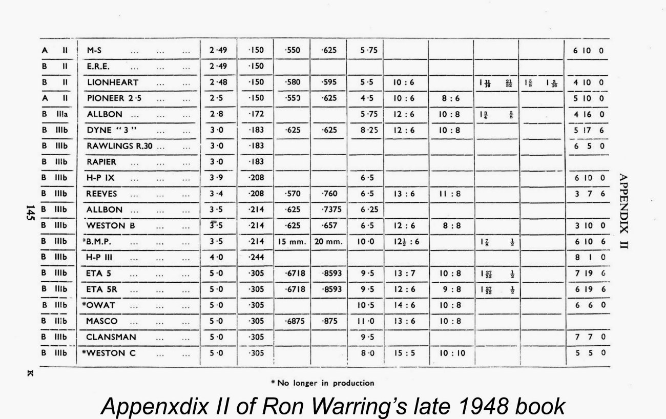 Warring’s book (compiled in late 1948) entitled “
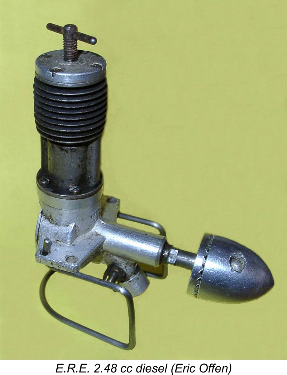 Following the winding-up of the B.M.P. venture, Henri Baigent continued to make model engines on his own account, now working from his own premises at 10 Beverly Gardens in Bournemouth. Ray Baigent recalled that a number of different one-off model diesels were successfully constructed during this period, including one having a displacement of only 0.075 cc - almost certainly one of the smallest engines to have been successfully completed in England at that time.
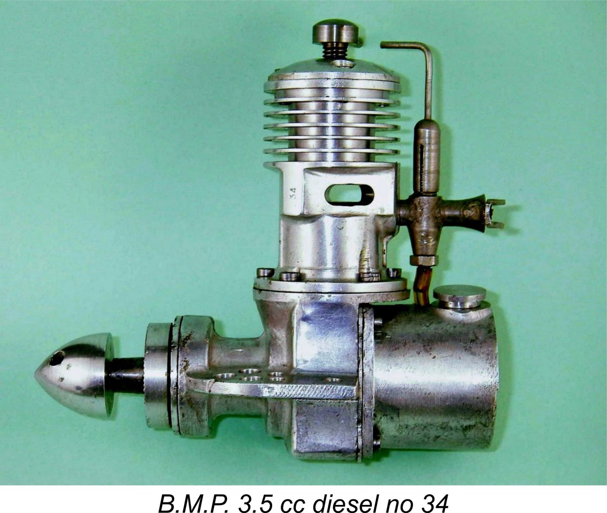 As noted above, the B.M.P. 3.5 cc diesel enjoys the distinction of being the first commercial English diesel to feature a twin ball-race crankshaft. In all other respects, its functional design follows the established contemporary diesel pattern of using long-stroke geometry allied to sideport induction.
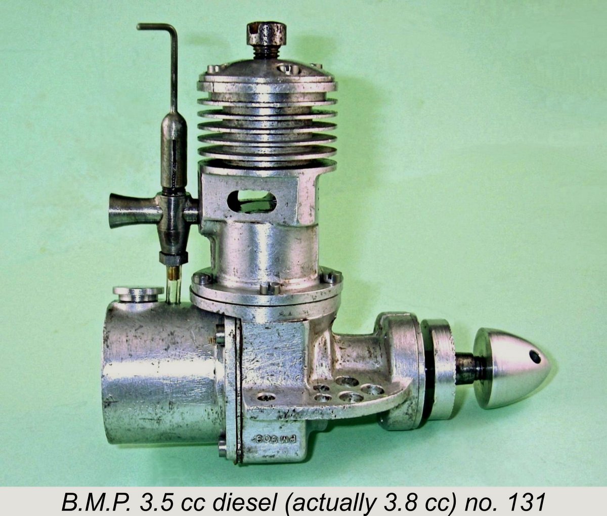
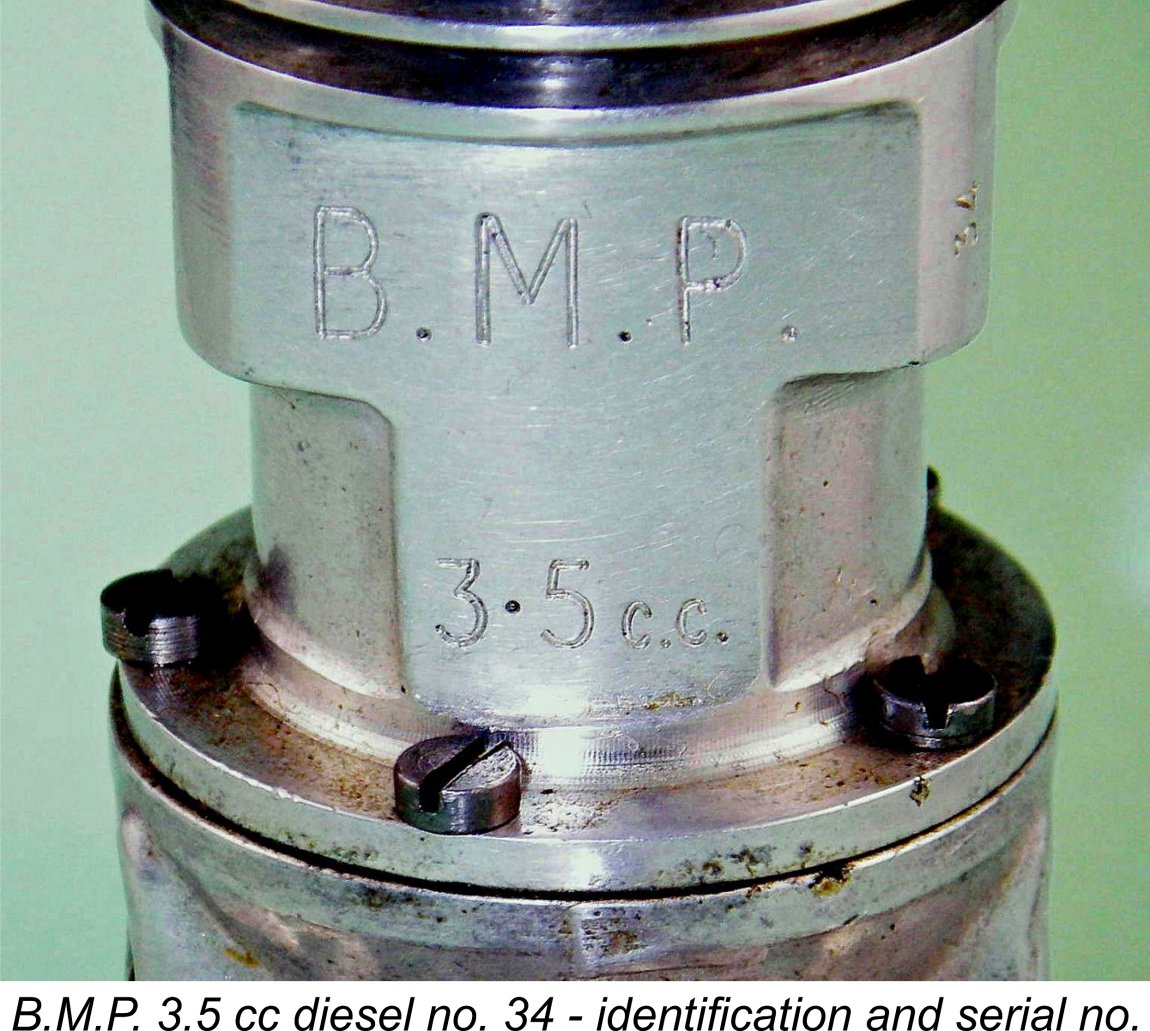 As stated earlier, the initial test batch of the B.M.P. 3.5 cc diesels displayed no serial numbers. I have personally yet to encounter one of those units. The later series-production examples did carry such numbers. My own lower-numbered example bears the serial number 34 neatly stamped vertically in quite small figures on the forward end of the left-hand exhaust "stack" (viewed from the rear) just to the side of the stamped initials "B.M.P." (as written, with periods) which appear on the front of the transfer bulge along with the stamped designation "3.5 cc" just below.
 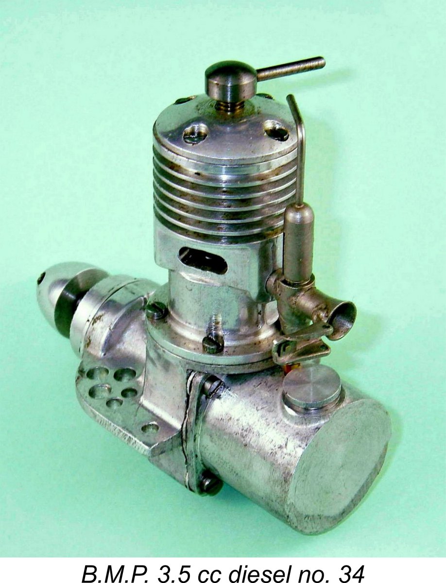 Functionally speaking, the engine is of the conventional side-port pattern. There are two exhaust ports set somewhat towards the rear of the cylinder rather like those of the much later
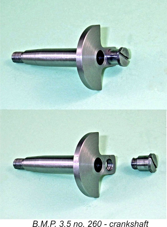
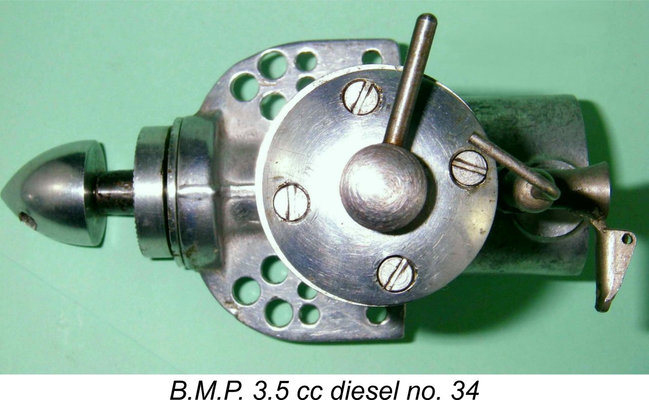
 At the rear, the carburetor body is made up from two steel components which are brazed together to form a classic + shape. The delivery end of the intake threads into a tapped hole at the rear of the crankcase using a ¼-40 Model Engineer thread with no lock-nut. The carburetor is actually one of the most interesting features of this engine. I was forced to take a really close look at the carb from engine number 34 when my second example no. 131 arrived as a bag of bits missing the entire carburetor assembly (among other things).
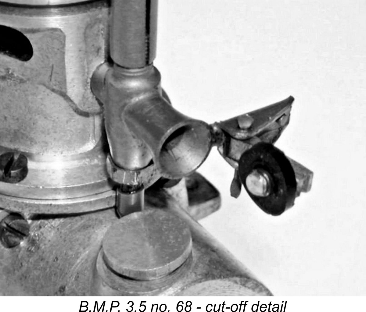 Engine no. 34 was originally equipped with a spring-loaded choke flap which is now missing, although its mounting remains brazed in place along with the base of the flat spring. The spring apparently held the choke flap in the open position, and a timer could presumably be arranged to snap it shut to stop the engine when desired.
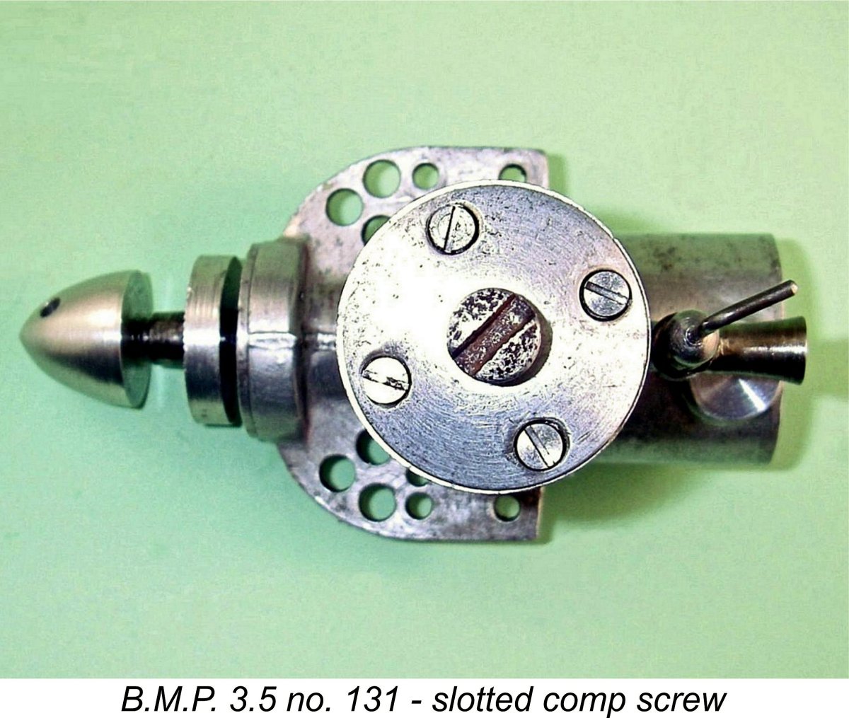 My illustrated example no. 34 has a conventional compression screw with a single-arm tommy bar, as did the example which was illustrated by Peter Scott in his little International Aero Engine Collectors' Society (IAECS) book from long ago (anyone else remember that?!?). Others, including engine nos. 68, 105 and 131 as well as the example featured in issue #1 of MEW and the one in
 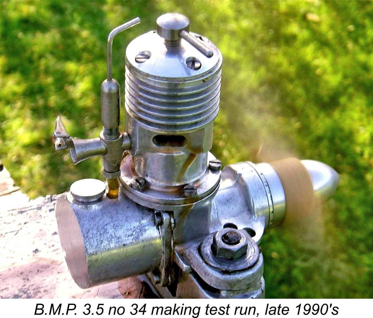 I didn’t test that engine for the earlier article on MEN, presumably because of time constraints. Instead, I relied upon my notes from some far earlier test runs which I had put on in the late 1990’s, just for fun. Not being aware at that time of the likelihood that this engine's crankpin had a right-hand thread, I tested it in the conventional anti-clockwise direction viewed from the front. The crankpin must have been screwed home very tightly, because I didn't experience any problem with an unscrewing crankpin.
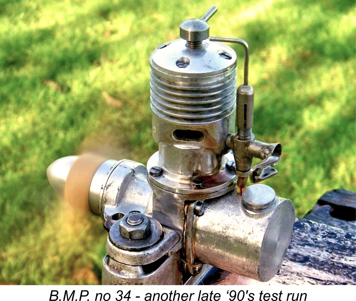
 The tank has an extremely generous capacity, and I found that it gave a leaned-out run of well over 4 minutes. This would be OK for control-line or model boat use, but is of course extremely excessive for free flight purposes. For the latter application, the use of the cut-out would be mandatory.
 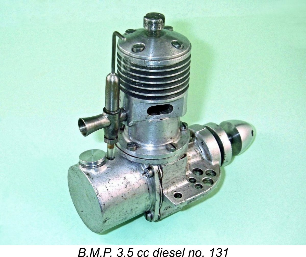 My second example, 3.8 cc variant no. 131, arrived far more recently as a bag of bits! It was missing a number of components, including the spinner, all assembly screws, the tank filler cap, the entire carburetor assembly and the needle. In addition, one of the three small countersunk screws that retained the front bearing cover plate was sheared off flush with the material of the bearing housing. However, thankfully all threads remained in good condition.
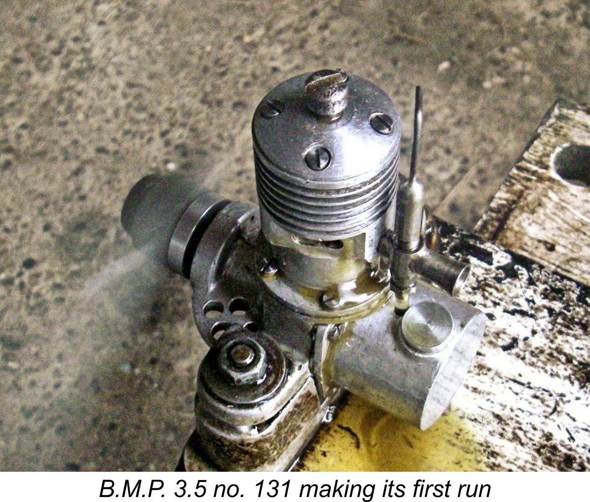 Once that was done, I mounted engine no. 131 in the stand to see how it ran after its rebuild. As I had already noted, compression seal was rather on the marginal side, but the engine started up readily enough with the help of an oil prime and ran perfectly well, with very positive response to both controls. I saw a steady speed of 5,000 RPM on the APC 11x6, indicating an output on that prop of around 0.071 BHP with presumably more to come on smaller props if my earlier notes are to be believed with respect to the engine's preference for somewhat higher speeds. The very leaky piston was obviously not helping either.
 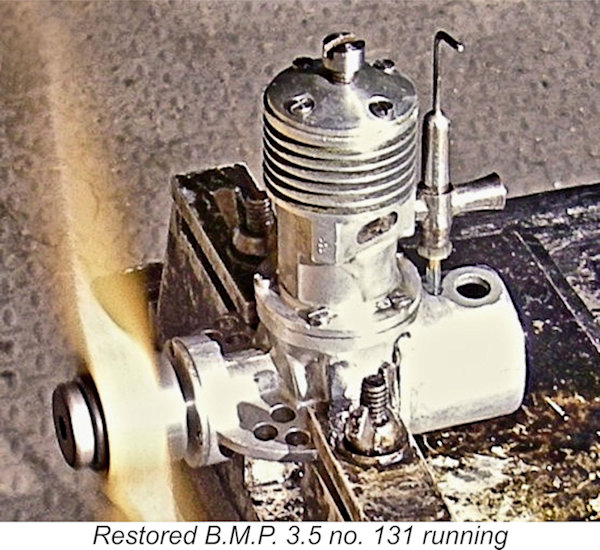 Dean confirmed that, like engine no. 260 mentioned above, this example had a screw-in crankpin with a right-hand thread. This being the case, it's somewhat remarkable that it survived its initial anti-clockwise test running in my hands without experiencing the unscrewing of the crankpin which had befallen engine no. 260. It appears that the engine will stand anti-clockwise running if the crankpin is screwed home really tightly. Even so, Dean concurred with me that the engine really should be operated in a clockwise direction viewed from the front - he tested it in that direction, as seen
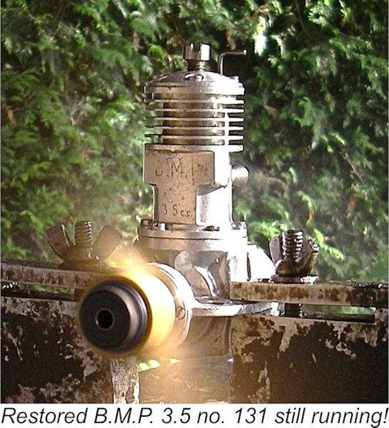
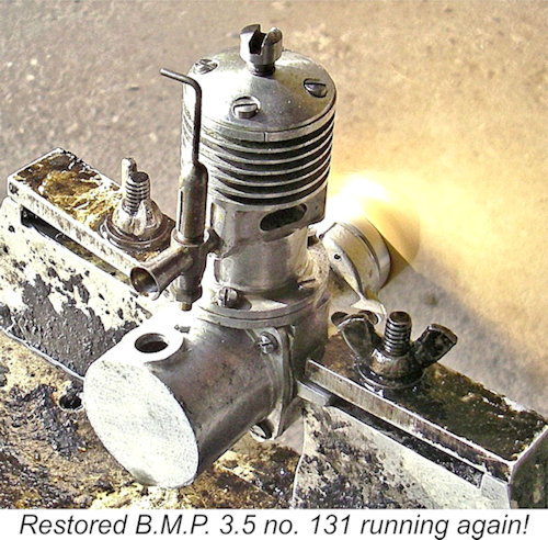 A switch to a 10x6 wide-blade pusher prop cut-down from a 12x6 Zinger saw the speed jump to 6,300 RPM - around 0.118 BHP based on previous testing with that prop. Evidently, the engine had already passed its peak by that speed. Confirmation of this impression was obtained by fitting a Top Flite 10x8 wood tractor prop and running it in a clockwise direction in pusher mode. I had to keep these runs short given the relative absence of cooling air, but nevertheless saw a speed of 6,000 RPM - around 0.131 BHP. It appears that the engine peaked at some point in the upper half of the 5,000 RPM range.
 | |