
|
|
The Milford Mite - England's Worst Ever?
My original article on the Milford Mite appeared on the late Ron Chernich’s fascinating “Model Engine News” (MEN) website in August 2009. However, my mate Ron left us in early 2014 without sharing the access codes for his heavily-encrypted site. Because no maintenance has since been possible, the MEN site is slowly but perceptibly deteriorating - a sadly inevitable process which can have only one ending in the long run. I was unwilling to risk the loss of the information so painstakingly gathered on the Mite, hence the article’s re-publication here. Moreover, a considerable amount of additional information has subsequently come to light as a result of some much-appreciated further research by my Aussie mate Gordon Beeby. As a bonus, the re-drafting of the article has allowed me to correct some errors and omissions in the original text as well as present some more authoritative test data. Before embarking upon this review, I'd like to pay tribute to my good friend and valued colleague Kevin Richards. Kevin was unsparing of his time in tracking down published information on the Mite, including many of the advertisements for the engine. He also supplied a number of images for me to use as illustrations to the following text, some of which resulted from his dismantling of his own example to expose the innards. As if this wasn’t enough, Kevin also read the initial draft of the original article and offered some very useful corrections and additions. So while I accept full responsibility for the content and conclusions presented in what follows, I'd like to make it absolutely clear that I couldn't have got to first base on this project without Kevin's help, which I hereby acknowledge freely and fully. Thanks, mate! OK, so how did an engine which acquired such a sorry reputation come into existence and survive for well over a year in the diesel-savvy post-WW2 British market? In order to understand that point, it’s necessary to review the context within which the engine appeared. I’ll begin by doing just that. Background Following the conclusion of World War II, Britain went through a difficult period as the wartime industrial machine geared down, leaving many redundant wartime production workers joining the large numbers of de-mobilised Service personnel in facing the challenge of readjusting to peacetime life. The country's infrastructure had suffered greatly in the conflict, while many staples continued to be in short supply. Ready cash was tight and it was tough times all round for the average Briton. Winning a war is one thing - winning a peace is quite another!
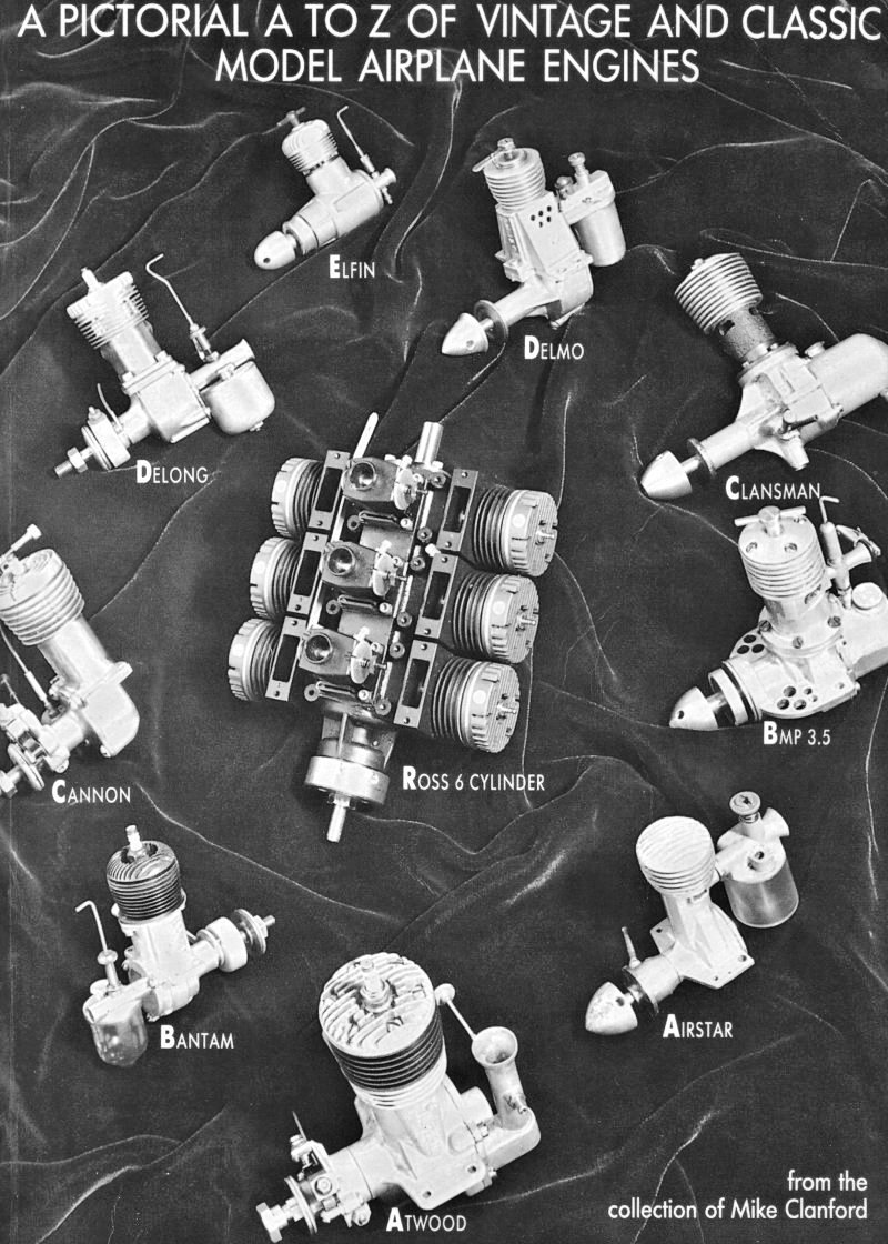
Probably the best-known and most successful of these British post-war model-related entrepeneurial ventures was the original Electronic Developments (Surrey) company, better known simply as E.D.. This venture was founded in 1946 by a group of former employees of the Parnall Aircraft company which had been engaged during the war in making Frazer-Nash gun turrets. However, in an often-repeated scenario following the cessation of hostilities, Ministry contracts were terminated, leaving many Parnall staff looking for other employment. A group of them joined forces However, there were other model engine manufacturing ventures established on a far smaller scale at around the same time which signally failed to leave a lasting mark on the model industry. A number of these took the form of one or two-man "garden shed" operations. In one case (the excellent Clan engines from Scotland), the manufacturing reportedly took place in a converted cowshed in Fife! For the most part, the products of these small-scale operations were manufactured in limited numbers for mainly local sale. As might be expected, the quality of these grass-roots "cottage industry" manufacturing operations varied widely. Some, like the aforementioned Clan engines, were very well made and gave complete satisfaction in use. However, this was not the case for all such productions! In this article we'll turn the spotlight on an early post-war engine that appears to have been the product of just such a small-scale manufacturing operation but has the reputation (deserved or otherwise) of having failed to come up to the generally-accepted British standards of the day. This is the often-maligned Milford Mite diesel of 1.41 cc displacement. This intriguing little engine has fared very poorly over the years in terms of its reputation. Motor Boy Ken Croft once characterized it as "probably the worst diesel ever made in England". Mike Clanford commented in his A-Z compilation (page 130) that the engine's name was incorrectly spelled and that a more appropriate spelling would have been "Might" as in might (or might not) run!! The late O.F.W. Fisher stated on page 26 of his 1977 “Collector’s Guide to Model Aero Engines” that the Mite "left a good deal to be desired in many ways, and some consider that it falls roughly into the Slag category; although it in fact had a cylinder liner, and the engines would run". Well, some of them evidently would anyway! After the above litany, there's probably not a lot that I can say here that could make matters any worse for the reputation of the poor old Mite! However, in fairness to the much-abused little beastie, it seems only right that we should give it a fair trial before acceding to the general condemnation! This requires that we take a somewhat closer look at the engine and objectively determine the true extent to which it lived down to its sorry reputation. Let’s get right to that! Overview
Although the Mite was advertised nationally and was undoubtedly sold in model shops both within and beyond the London area, even being claimed by the makers to have found its way to foreign climes, it seems probable that the engine was sold locally for the most part, in many cases through direct sales from the Rayners Lane shop. Indeed, buyers were encouraged to come to Harrow to see their engines tested before they took delivery - a very direct form of marketing indeed, and one which displayed notable confidence in the engine's ability to perform on demand! Despite the sincere efforts of the makers to promote the engine, its present-day rarity leaves little doubt that overall production figures were quite low. Unkind critics of the Mite have suggested that the rarity factor may be due in part to many of the engines that were sold ending up in the dustbin after their disgruntled owners had given up on them! It's my intention in this article to explore the basis (if any) for such a dismissive point of view, which has been widely expressed in the past.
One very interesting and often overlooked feature of the Mite was the fact that its crankshaft was supported by a single ball race at the rear end adjacent to the crankweb. This actually gives it the distinction of being one of the very first British ball-race diesels, along with the contemporary B.M.P. 3.5. The presence of the ball race and the thickness of the crankweb (see below) jointly explain the rather massive appearance of the front portion of the main crankcase casting.
As can be seen in the accompanying comparative view, the Mk. III Mite is actually a little more compact than the Mills despite its slightly greater weight and larger displacement. No doubt the ball race and unusually thick crankweb account for much of the weight difference.
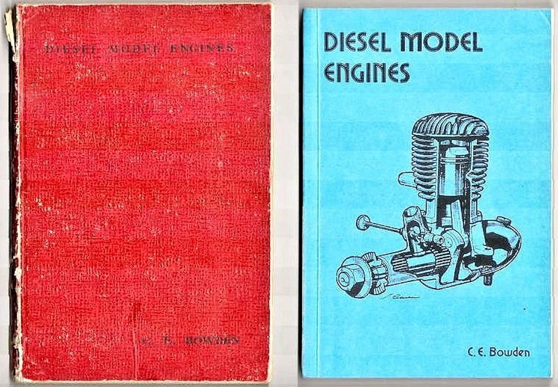
The Mk. I version of the Mite seems to have appeared by November 1946, since it was first advertised in the December 1946 issue of "Aeromodeller" as reproduced below at the right. This places it among the pioneering British model diesels. The advertisement was interesting in that the engine's displacement was cited as 1.5 cc. I suspect The advertisement quoted an introductory price of only £1 for a set of unmachined components and instructions. Finished engines were offered at £3. By late 1946 standards, these were very competitive prices. A highly innovative marketing ploy was embodied in the invitation for customers to show up at the shop to watch their engines being assembled (and presumably tested). The Milford Mite was the subject of commentary by Lawrence Sparey (writing as "Artifex") in the May 1947 issue of "Aeromodeller". However, this original variant clearly didn't remain in production for long. As of July 1947, the Mk. II version of the Mite was being advertised for sale at a price of £4 ready to run - a considerable increase from the introductory price of £3. In common with several other manufacturers of the period, the Milford Gauge Company continued to offer the engine in un-machined "kit" form at an increased price of 30 shillings (£1.50), complete with blueprints and instructions. For an additional 20 shillings (£1.00), one could also get the engine in partially-machined form, but in this case one had to pay 3 shillings and 6 pence (£0.18) extra for the blueprint! It actually seems possible that at least some of the sub-standard examples which have given rise to the Mite's unsavoury reputation may have been the products of less-than-skilled home constructors. Can't blame the manufacturers for that! Mind you, the corollary is equally true - some of the better examples (like my own Mk. II and Mk. III units) may be the products of highly talented hobbyists - the Motor Boys of their day! We would actually expect to find a wide range of quality standards in different examples of an engine which was built both by its original manufacturers and by their amateur machinist customers. As one might anticipate with such a background, complete examples in good condition (by Mite standards ) remain very rare today (2022). Prices in the £350 - £400 range were seen for a "good" one at the peak of The Milford Mite does not seem to have survived long enough or made enough of a national market impression to have attracted much real interest from the contemporary modelling media. As a result, this is one of the more poorly-documented British engines. In fact, the makers themselves created much of the record in relation to the Mite through their advertising. I'll just have to do the best that I can on the basis of the few references that do exist coupled with an examination of several actual examples of the engine. As already noted, three distinct variants of the Mite are attested in the record. Page 130 of Mike Clanford’s well-known A-Z book includes photographs of two versions. A third appears in a captioned illustration in the 1947 first edition of Colonel C. E. Bowden's classic book “Diesel Model Engines”, although there is no accompanying description in the main text. The example in my own possession which formed the basis for the original 2009 version of this article is what Clanford calls a Mk. II, but there's All the evidence in my possession is undeniably consistent with the 1947-1948 production dating given by Clanford for the engine. For starters, all of the manufacturer's advertising that Kevin Richards and Gordon Beeby were able to dig up between them falls within these two calendar years. Furthermore, the Mite was not mentioned in the 1946 first edition of D. J. Laidlaw-Dickson's book “Model Diesels”, which implies that it had not yet appeared as of late 1946 when that book was completed. However, the original Mk. I version of the Mite was certainly in existence by November 1946, as confirmed by its previously-noted appearance in that December 1946 advertisement, making due allowance for Editorial lead time.
It seems likely that the 1.5 cc figure was derived from the manufacturers' own advertising, as mentioned earlier. The cited 1.5 cc model lacking a Mk. number was almost certainly what I've called the Milford Mite Mk. I. The 1.41 cc displacement figure given for the Milford Mite Mk. III is consistent with the factory-cited displacements for the Mk. II and Mk. III variants. However, there are some serious discrepancies in the table's dimensional data which call their veracity into question. For starters, the 11.75 mm figure given for the bore of the Mk. III Mite is at odds with the manufacturer's cited figure of 15/32 in. (11.91 mm), which has been confirmed through direct measurement of my own examples. The same comment applies to the 12.00 mm bore shown in the table for what I assume to be the Mk. I model. Moreover, neither reported bore yields the associated displacement claim in conjunction with the 1/2 in. (12.70 mm) stroke - try it for yourself! I'd actually hazard a guess that all three variants actually shared the same internal working dimensions along with the same 1.41 cc displacement, the discrepancies in the table simply resulting from the failure of the compiler(s) to take their own independent measurements with sufficient accuracy (or to take them at all). By contrast, the engine was not included in the table of model diesel engines for the years 1948-51 which was compiled in 1951 by Ron Warring for “Model Aircraft” magazine. We know that Warring was certainly aware of the Milford Mite, since both Mk. II and Mk. III variants of the engine were included in the listing of British engines which appeared in Warring's early 1949 book “Miniature Aero Motors”. However, the Mite was listed in that work as being no longer in production and there's no comment about it in the main text. This is certainly consistent with the idea that production ended in 1948.
In addition, Warring fails to mention the ball race shaft, citing the bearing as merely a plain bushing. It appears that he may have been going on the basis of somewhat inaccurate second-hand information and did not check his sums all that closely! Further confirmation of our postulated dating is to be found in the late Vic Smeed's very informative 1986 compilation "Fifty Years of Aeromodeller". On page 34, the author notes that by the Spring of 1947 there were no fewer than 14 British-made engines on the market and that by early 1948 this number had doubled. The Milford Mite is specifically included in Smeed's listing of these engines, along with a comment that a number of British-made engines of the period were offered for sale for "only a few weeks before fading away". Based on the manufacturer's advertising researched by Kevin Richards and Gordon Beeby, the Mite actually did a little better than that! As far as Gordon Beeby was able to determine, the final appearance of the Milford Mite in the contemporary modelling media took the form of its inclusion in Peter Chinn's article entitled "Analysis of Engine Data" which appeared in the October 1949 issue of "Model Aircraft". This article consisted mainly of a Class-defined listing of all model engines (both British and overseas) then in some level of use in Britain. The "data" referred to in the title consisted of some basic numerical information (bore, stroke, displacement, weight, claimed performance) on each engine listed, along with a brief comment regarding any notable feature(s). It cites the bore and stroke dimensions of the Mite correctly, but otherwise adds nothing to our knowledge of the engine. The important point to note is the fact that the engine was It seems rather odd that the makers of the Milford Mite were apparently unconcerned regarding any possible confusion between their offering and the equally rare but (it must be said) far better-finished 0.73 cc Majesco Mite diesel which was on sale at the same time. There has in fact been some later confusion between the two contemporary British "Mites" (to confuse things even more, there was also a contemporary American-made 0.098 cuin. Mite fixed-compression diesel of completely different design!). Just to set the record straight, the Majesco Mite was designed and manufactured in Parkstone, Dorset by a gentleman named Jack Colyer, who was a friend of Colonel Bowden and an associate of Ron Warring. Indeed, Warring was closely involved with Colyer in the design and production of the Majesco Mite, as recorded in his previously-cited 1949 book. Colyer clearly had nothing to do with the Milford Mite from far-away Harrow. As stated earlier, the Milford Mite was an essentially conventional side-port design of its era, but it did display a number of rather unique features which set it apart from the rest. The basic design never changed, but certain details of the engine's construction were amended as time went by. Let's have a look at these amendments. Known Variants As far as is known, none of the Mite variants were ever assigned serial numbers. Accordingly, we have to deal with them strictly on the basis of the known Mark numbers assigned by the manufacturers.
I have been unable to locate either an example of this seemingly very rare variant or any other specific references to it. Evidently the Mk. I Mite was a short-lived initial version which was quickly amended for whatever reason. My apologies for the poor quality of the attached images scanned from the two books mentioned, but as these are the sole images of this variant of which I’m presently aware, we're stuck with them! Any image is surely better than none! The engine had evidently only just come to Colonel Bowden's attention when he This impression is heightened by the fact that Colonel Bowden actually seems to have been very poorly informed regarding this unit, citing its displacement as 1 cc instead of the actual figure of 1.41 cc (or 1.5 cc if you go by the "Aeromodeller Annual" table). Mind you, he was not alone in assigning this displacement to the Mite - a December 1947 advertisement placed in “Aeromodeller” magazine by the Hull Model Shops offers the "Milford Mite 1 cc" diesel at the £4 figure mentioned earlier. Remarkably, this was at a time when the makers were advertising the 1.41 cc Mk. II Mite directly above the Hull Model Shops advert on the same page in the same issue at the same price direct from the makers! Presumably dealers received a wholesale discount in order to give them a workable profit margin. Oddly enough, Laidlaw-Dickson (writing at roughly the same time as Colonel Bowden about the same model) got the displacement correct - he quoted it as 1.41 cc. There seems little doubt that this was the engine's true displacement and that the figure quoted by Colonel Bowden and repeated by the Hull Model Shops was in error.
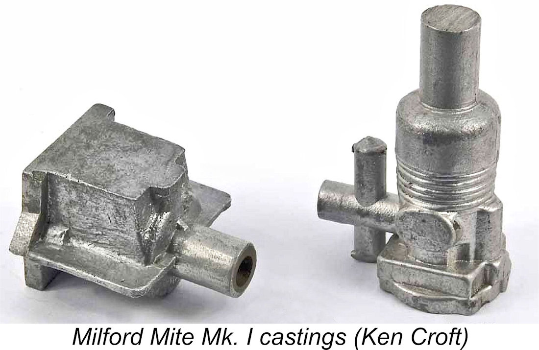
The initial version of the engine was distinguished from its immediate successor mainly by the design of its cylinder jacket. Based on the illustrations, it’s evident that the cylinder liner was contained inside a full-length cast and machined upper cylinder unit which incorporated the stub exhaust stacks, the carburettor body and a series of closely-spaced cooling fins of circular form along with the bypass passage (visible at the front) and the cylinder head with its tapped hole for the compression screw. Quite a complex piece of casting! Like all the other cast components used in this design, it appears to have been produced by gravity die-casting. Ken Croft's attached image of a couple of castings for this engine provides a good deal of clarification regarding the form that they took.
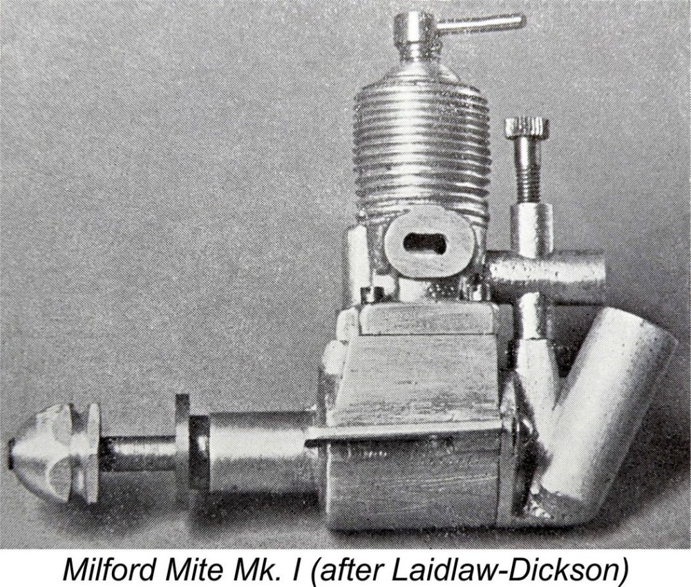
The tank was a most interesting if rather impractical design, being formed as part of a single casting of unusual complexity which doubled as the backplate. This unit was attached to the crankcase from the rear by two screws, and the fuel pickup tube extended downwards from the carburettor into a vertical cylinder which opened into the base of the tank and was cast in unit with the tank and backplate. The tank itself was of cylindrical form and was most unusually angled backwards. It was internally threaded to accommodate a screw-in full diameter plug at its open end with a vent for air admision. More of this below................ Unlike Colonel Bowden's first edition, Laidlaw-Dickson's 1947 second edition included a comment in the main text in addition to the illustration reproduced above. The writer made a few statements which actually have great relevance to this discussion. Since this is the closest thing that we possess to a contemporary "review" of the engine, it seems worth quoting in full: "On practical considerations we must mention the Milford Mite - another newcomer of 1.41 cc. This engine on first sight fails to impress. It lacks those qualities of high grade finish that other manufacturers have concentrated upon. The intended buyer should not be misled by this apparent roughness however. It is what goes on inside that must be the final test. Here will be found that high degree of compression and absence of play so necessary in a small engine. In addition the manufacturers invite buyers to test their own engines in their workshops before taking them away, and what can be fairer than "try before you buy"". In summary, Laidlaw-Dickson was saying that what the engine lacked in immediate eye appeal was more than compensated for by the quality of its internal fitting and finish. He also commented upon the evident confidence in their product which was displayed by the manufacturers. Both comments appear to fly directly in the face of the long-standing legend of the Mite's shortcomings! It's also worth mentioning that the previously-mentioned May 1947 commentary by "Artifex" (aka Lawrence Sparey) was completely consistent with Laidlaw-Dickson's assessment, characterizing the Mk. I Mite as "a diamond in the rough".
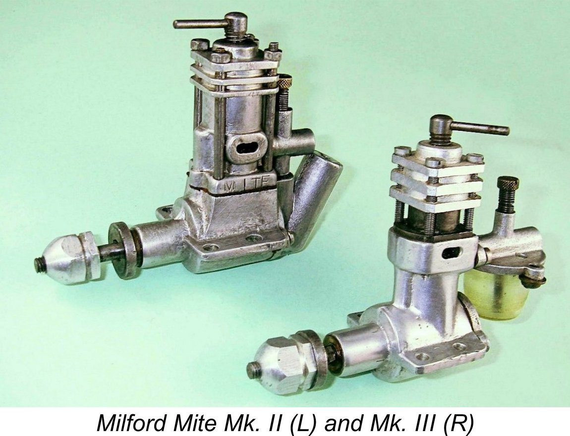
The Mk. II Milford Mite (which Mike Clanford incorrectly calls the Mk. I) retained the same general design layout as well as the same bore and stroke as its predecessor, but exhibited some significant design changes to the upper cylinder jacket. The exhaust stacks and carburettor mounting remained unchanged, but the former circular cooling fins were gone - indeed, the revised jacket was far less well provided with cooling fins. Presumably experience had shown that cooling was not a problem with this design when used in its intended sport free-fight application with associated short runs. Indeed, the absence of fins would promote a quicker-than-usual warm-up, which would be an advantage with such short runs. The sole residual concession to engine cooling was the provision of only three shallow and rather thick integrally-cast cooling fins at the top having a square plan view as opposed to the former circular shape. These fins added very little to the available cooling area, evidently being included more because the customers would expect to see cooling fins than for any other reason! However, advantage was taken of the four "corners" of the square-section fins to replace the former short cylinder attachment screws at the base with far longer studs passing from the cylinder head through the corners of the three cooling fins and on down through holes in the base flange into the same tapped holes in the main crankcase casting that had been used formerly. These studs were exposed for much of their length. They were topped with matching nuts. The only other change worth noting is the addition of the word "MITE" stamped rather haphazardly onto the left-hand side of the upper cylinder base flange. The unique fuel supply arrangements continued unchanged in this second variant, as did the main crankcase casting. Indeed, apart from the revised upper cylinder jacket and method of fastening, this variant appears to be more or less identical to that which appeared in the books by Col. Bowden and Laidlaw-Dickson.
The carburettor body on the Mk. II Mite is cast integrally with the upper cylinder casting. It seems very likely that this was a continuation of the approach applied to the manufacture of the Mk. I model described earlier. The intake tract has a true venturi profile, the measured diameter at the throat being a mere 0.120 in (3.05 mm). Perhaps the greatest disadvantage presented by the use of this very individualistic type of tank was the fact that the design rendered it quite impossible to use the engine with any alternative fuel supply arrangements. The very small tank capacity clearly restricted the engine to free flight applications, and removal of the standard tank to connect the engine to an alternative tank also involved removal of the backplate! Hence it was impossible to connect any form of alternative tank to this engine as supplied. Not only that, but the engine could only be mounted in the upright position - the tank would not hold fuel in any other orientation. At the time, inverted mounting was very popular among free flight modellers, while sidewinder mounting had become widely employed in control line designs. It would be completely understandable if the limitations imposed by this tank design had acted as a major sales deterrent. A compromise applied by quite a few owners was to remove the entire tank casting from the backplate. This was easily accomplished by turning in a lathe or even by the careful use of a hacksaw and file. The existence of a few examples which have been modified in this way has led to a belief that the Mk. II Milford Mite was offered in Series 1 (tank) and Series 2 (tankless) forms. Ted Sladden proposed this scenario in his highly-recommended book “British Model Aero Engines - 1946 - 2011”. However, there’s no supporting evidence to be found either in the media or the advertising record. I believe it to be far more likely that all of these engines began life as standard Mk. II units which were modified either by their owners or by the manufacturer following their return (see below). A tentative attempt to dismantle my example of the Mite Mk. II proved futile, since the cylinder assembly proved to be mated to the lower crankcase unit "for keeps" and I was not willing to force matters given the engine's generally excellent condition. Since removal of the backplate is not possible without prior cylinder removal, I am unable to go further in my description of the Milford Mite Mk. II.
The Mite was also featured in the November and December 1947 advertising placements by Super Model Aircraft Equipment of Queens Road, East Sheen, London S.W. 14. Those advertisements offered the company's Gnat free flight pylon model kit complete with Milford Mite engine for £4 17s 6d (£4.87). It makes for an interesting comparison to note that the same kit with a Mills 1.3 cost £6!! The third and final variant of the Milford Mite which has come to my attention is the Mk. III, which Clanford incorrectly designates the Mk. II. In this final variant (as far as I’m aware), all of the main castings have been completely changed (requiring that new patterns be made), while the fuel system has been substantially updated.
The copywriter of the Milford Gauge Co. advertisement (presumably the effervescent Mr. Smith) once again revealed his chatty style and strong sense of humour by printing an amusing letter ostensibly from a dealer which complains that the Mite was "too square" and was scaring off potential customers because of this!! The text is revealing in that it cites the reason for the minimal cooling provisions on the Mite as being the need to avoid over-cooling in the British climate! There may in fact be something in all of this…………….. A further advertisement for the Mite Mk. III appeared in the June 1948 issue of “Aeromodeller”. The style of this placement was quite different, however. It seems that things had got a little serious for the manufacturers by this time. For one thing, Mr. Smith had apparently exhausted his sense of humour and did not include any of his witty comments as he had done previously. The advertisement was strictly business in nature.
In addition, the makers were now offering a fully machined set of castings needing only assembly and running-in for £3 3s 0d (£3.15) - the un-machined castings were no longer on offer. Most interestingly, the company was offering fully-guaranteed reconditioned Mk. II’s for only £3 even. In other words, they were undercutting their own Mk. III model! From new design to "reconditioned special" in less than a year strongly suggests that a lot of Mk. II’s had been returned as unusable and had had to be "reconditioned" to render them serviceable. It seems not unlikely that the limitations imposed by the fuel tank arrangements may have contributed to the high return rate. Perhaps this In discussing the Milford Mite Mk. III, we are now dealing with a variant for which an accurate and detailed description can be provided, since one of my own examples of the Mk. III engine could be partially dismantled for internal inspection. Moreover, Kevin Richards was kind enough to fully dismantle one of his examples to provide further clarification. As a comparison of the various images will confirm, this variant displays a wide range of design departures from its two predecessors. The crankcase casting is completely different, the upper cylinder casting has been eliminated altogether and the carburettor and fuel tank arrangements have been completely revised. Let's have a close look at an actual example of this version of the Mite. The Mk. III Mite - Detailed Description It appears that the changes in evidence on the Mk. III Milford Mite to be described below were made at least in part to cut down on the amount of casting involved. The design revisions resulted in the elimination of two relatively massive and complex castings in favour of a pair of far simpler and smaller castings.
Although still pretty massive, the crankcase casting was somewhat more "streamlined" and compact than that of its predecessor, also being externally contoured to make provision for the inclusion of some internal machining to allow for con-rod clearance. More of this below. One good feature of all models of the Mite was continued in the new design. This was the use of mounting lugs of very substantial length, with a relatively wide longitudinal mounting hole spacing. The lugs and mounting holes were centred slightly forward of the cylinder axis, more or less on the engine's centre of mass. The design was such that a solid mounting was more or less assured. One slightly unusual feature was the fact that the lugs were centred upon the axial centre line of the crankshaft, leaving the shaft centre line a little above the plane of the mounting surfaces. All of these arrangements were later to re-appear in the Elfin 1.49 and 1.8 BR models.
And it doesn't stop there - the two lugs cast into the sides of the backplate to accept the retaining screws on each side were made somewhat oversize, presumably to reduce the possibility of their opening up under wedging stress applied by the assembly screws. Again, not a bad idea, but the consequence was that the lower edges of the backplate lugs once again extended well into the plane of the model’s bearer surfaces, requiring that the bearers be notched to accommodate this anomaly. Annoying! Bore and stroke of the engine remain unchanged from the Mk. II variant at 11.91 mm (15/32 in.) and 12.70 mm (1/2 in.) respectively for a displacement of 1.41 cc. The figure for the bore differs from that given in the "Aeromodeller Annual" table reproduced earlier, but I can't help that - the above figures are derived from direct measurement. They are also consistent with the prevailing British precision engineering practise of designing to fractional nominal dimensions. The main bearing appeared to be unchanged from the earlier variants. The single ball race at the rear was carried over to the new model. At the front end, the plain bearing section had a nominal as-cast external diameter of 0.500 in. and was equipped with a thick-walled bronze bushing in which the 0.250 in. dia. crankshaft journal ran. This bushing had an O/D of 0.391 in. (nominally 25/64 in.), which means that there was actually not a lot of cast metal left around the bushing itself. Given the fact that the main bearing of this variant was not equipped with reinforcing gussets, the design would appear at first sight to be a bit anaemic in terms of crash-resistance at the point where the main bearing met the front of the crankcase casting - some stiffening gussets might have been a good addition. Indeed, vestigial gussets had been a feature of the earlier versions of the Mite. The manufacturers appear to have been aware of this issue, and in the revised model the reduction in diameter from the ball race housing down to the front bearing "stub" was moved forward in the new design to coincide with the forward ends of the mounting lugs. The result of this change would have been a So much for the revised crankcase. Turning now to the steel cylinder, Kevin Richards' accompanying image confirms that this was a simple tubular item equipped with a conventional locating flange immediately above exhaust port level. The flange was squared off at the sides and rear to match the case but was left in its turned configuration at the front, matching the curved contour of the main casting at that point. The corners of the flange were drilled through to allow the passage of the four long cylinder hold-down screws which replaced the former studs on this variant.
The revised cooling jacket was retained in place by four long hold-down screws which replaced the studs used on the previous model. These screws passed through holes drilled in the corners of the squared-off fins, thence passing externally down the cylinder and through the corners of the cylinder flange to engage with four tapped holes in the crankcase. Hence they retained both the cooling jacket and the cylinder itself. The screws were fully exposed for a substantial proportion of their length. At the rear, things were very different again. An entirely new carburettor casting was employed which included a very substantial integrally-cast tank top. This unit was attached to the rear of the main crankcase casting by two screws which passed through the outer corners of an integrally-cast flange to engage with tapped holes in the flat carburettor mounting surface at the rear of the upper crankcase. This arrangement replaced the integrally-cast construction formerly used.
This tank arrangement had several significant advantages over that used in the previous model. For one thing, it had a far more practical fuel capacity. In addition, the revised carburettor assembly could be removed, rotated axially 180 degrees and remounted in an orientation suitable for inverted mounting of the engine. Moreover, the standard tank could be dispensed with altogether and the engine supplied from any tank of the owner's choosing. This meant that the standard hang tank could be used with the engine either upright or inverted and sidewinder mounting was also perfectly possible provided suitable alternative fuel supply arrangements could be made. This one change made the revised model far more flexible in terms of potential applications. The tubular main jet was made of copper and screwed into the underside of the casting. It doubled as the fuel pickup line. The externally-threaded needle appeared unchanged from that used previously. It screwed into a boss on the upper side of the casting and was tensioned with a coil spring. Since the screw-in main jet stopped at the wall of the venturi opposite the needle, the unit operated on the surface-jet principle which was then very popular in England and elsewhere. The backplate was a very much more compact casting than its predecessor since it no longer incorporated the fuel tank. It was a simple un-recessed (and hence quite heavy) casting which was machined at the front to fit the rear of the crankcase. A gasket was used to seal. As mentioned earlier, the backplate was attached to the rear of the crankcase using a pair of screws which passed through the two hold-down lugs at the sides to engage with tapped holes in the mounting lugs, which were slightly expanded at those points.
An interesting feature was the complete absence of any form of serrations or knurling on the driving face of the prop driver. This was a not-uncommon approach at the time, and in fact prop slippage is not a problem with this engine in my direct experience. The arrangement actually has an advantage in that it allows for some prop slippage during a hydraulic lock or crash impact, which could be beneficial in protecting the crankshaft or other components from breakage. Some examples are seen with a pair of driving pins set into the face of the driver, but these may possibly be an owner modification. So much for what can be learned from an external examination! I'm always a bit reluctant to start pulling apart the older and rarer engines in my collection unless repairs are needed (which they weren't in this instance). In the case of the Mite, I decided that I would be prepared to remove the carburettor and backplate for inspection and photographic purposes. However, I did not wish to disturb the working components in any way given that they were already well "acquainted" and needed no attention. So off came the entire tank assembly, followed by the backplate. Both of these items are secured by 6BA screws, thus being easily removed. These actions were sufficient to reveal the main features of interest in this design. As it turned out, there are one or two such features!
The single ball race is located in a machined recess in the crankcase just forward of the crankweb. It provides excellent radial support for the shaft at that critical point. As mentioned earlier, the forward end of the crankshaft is carried in a bronze bushing which is pressed into the main casting in the usual way. The con-rod is made of steel. The component in my example appears to have been hand-filed from a piece of flat plate! It is undeniably a bit on the crude side by comparison with the work produced by other contemporary British manufacturers. However, it appears perfectly adequate for the job, with good bearing fits at both ends. At least one does not have to look at it while using the engine!
The reason for the angled "columns" cast externally into the crankcase casting at the sides above the mounting lugs becomes apparent immediately upon looking inside the crankcase - in order to provide swing clearance for the con rod it was necessary to form two angled channels in the crankcase interior at the sides. This appears to have been done by milling. The engine is quite conventionally ported along very similar lines to the contemporary E.D. Mk. II and Comp Special models. Exhaust porting consists of a pair of milled rectangular openings which feed into exhaust slots formed in the sides of the crankcase casting. A single transfer port of elongated oval shape is supplied with mixture through the front bypass passage mentioned previously. This bypass passage is quite large and has been produced by milling. The actual transfer port is located quite low in the cylinder wall, necessitating the use of a step in the piston crown, exactly as in the two E.D. models mentioned above as well as the competing Mills diesels. The relatively massive piston is machined from cast iron. It has cutaways in the skirt fore and aft. The front cutaway greatly improves gas access to the bypass passage. It is a feature that E.D. would have done well to copy on their 2 cc models - it is a commonly-encountered and extremely effective modification on those engines. The rear cutaway serves no functional purpose apart perhaps from balancing (and lightening) the piston - it merely dictates the vertical positioning of the induction port. In defiance of the Mite's reputation, the piston fit in both of my Mk. III examples is beyond reproach - compression seal is outstanding, yet there is no trace of stickiness anywhere. The contra pistons are equally well fitted - in fact, if anything they’re a touch on the tight side. It is of course possible that the engines have been rebored at some point, but there's no actual evidence for this. Indeed, both of my examples give the overall appearance of having had relatively little use. Although they have clearly seen some service, I'd expect rebored engines to look a little more "beaten up".
One possible point which could affect consistency should be mentioned here. There is no positive provision for the accurate location of the carburettor assembly on the mounting surface described above. The two screws are the sole means of locating the unit, and they provide no guarantee of precisely correct alignment between the venturi tube and the opening at the rear of the crankcase. The holes in the mounting flange are a sufficiently loose fit that the unit has slight lateral freedom of movement prior to being fully tightened. For best performance, it's necessary to inspect the alignment through the open end of the venturi to ensure that the unit is more or less correctly located. The carburettor casting and the fuel tank arrangements were described earlier. When we examine the actual venturi with the assembly removed, we find some evidence that the maker(s) of this engine knew at least a little about what they were doing! The induction tube has a genuine venturi shape, with a sharper opening angle beyond the point of fuel input than the closing angle prior to that point. The tube tapers steadily from a generous 0.232 in. (5.89 mm) diameter opening at the rear to a throat diameter of only 0.116 in.(2.94 mm), fractionally smaller than the corresponding diameter in the Mk. II Mite, although this The fuel pickup tube, unusually made of plain 1/8 in O/D copper tubing, is externally threaded at the upper end and screws into the central boss on the underside of the venturi casting opposite the needle boss. The pickup tube is installed as-is with respect to its internal diameter, no attempt having been made to provide a smaller jet orifice for better fuel atomization. This requires the use of a needle tip of unusual thickness. The needle is a more or less conventional externally threaded item which is effectively held at its setting by a light coil spring. Its one unusual feature is that the needle control and the needle itself are turned integrally from a single piece of brass, rather than having a steel needle inserted in the more customary fashion. All in all, the Mk. III Mite proves upon examination to be a basically conventional sideport diesel of its period, albeit one with a certain quirkiness in terms of its appearance and construction which give it a character all its own! The Quality Issue Since there's seldom any smoke without at least a little fire, it's pretty clear from the various comments recorded down through the years that many examples of the Milford Mite must have fallen well short of the standards expected from British model engine manufacturers by 1947/48. Indeed, there may be some truth in the earlier comment that one reason for the relative scarcity of surviving examples could be that many of them went straight into the rubbish bin after their owners gave up on them in disgust!! Some of these may of course have been sub-standard attempts by home constructors to make an engine from the casting sets supplied to order. Having made the above statement, I'm now going to start sounding like a bit of a heretic by flying in the face of legend - objective honesty compels me to say that my own examples of the Milford Mite are actually quite well made, especially where it really counts! I commented earlier that the piston fit in my pair of Mk. III engines is notable for the excellent compression seal combined with a virtual absence of any "stickiness" at any point in the stroke. The contra piston is equally well fitted. Crankcase compression too is first rate. There is a Prior to the original publication of this article on MEN in August 2009, I had only a single example of the Mk. III Mite. Subsequently, I was fortunate enough to acquire the illustrated example of the Mk. II Mite from my friend Mel Reid. Although it had clearly seen considerably more use, it proved on direct examination to be just as well fitted throughout - the slightly “softer” compression seal seemed to be a reflection of previous use rather than anything else. It is just as roughly finished externally as its later companion, but seems to be very well put together internally where it really counts. It started and ran very well indeed on initial bench testing. More of its test performance below................ To add to the knowledge database, I later acquired a second example of the Mk. III Mite, finding it to be just as well fitted as its previously-acquired companion. If they were all as well made as these three examples, I'd have to say that the Mite would scarcely deserve the almost universal opprobrium that has been heaped Even so, it actually appears that my engines are not unique and that there were at least some other examples that were well enough fitted to run OK. Mike Clanford claimed on page 130 of his A-Z book that his illustrated example of the Mk. II Milford Mite ran "well" (but see below!). Fisher too made the general statement that the engines "would run". As we shall see, my own examples go one better than that - they run well enough to fly a model quite effectively. Indeed, they all appear to have done so at some point! Further proof of the Mite’s ability to fly a model comes from Ken Croft, who provided several images of Bob Close’s “Wasp”, a 1938 design by L. S. Widgor, powered by a Milford Mite Mk. II with the tank removed as described earlier.
So two of the three running examples of the Mk. II that I thought I could report turn out to be one and the same engine! To offset this, Kevin recalled that although he never ran this example while it was in his possession, he did own another example of the Mk. II Milford Mite some years ago which ran "very well indeed" (to use Kevin's own words). One individual who applied his considerable model engineering talents to the challenge of sorting out a Mk. II example of the Mite was my friend Ken Croft, now of Somerset, England. Following some well-considered intervention to sort a few issues, the engine was turned into a "good runner" by Ken's own account. So the count of known operable examples of the Mk. II Mite has increase to four! I'm sure that there are other equally capable examples lurking about!
I confess to a sneaking suspicion that many of the really bad examples of the Mite were the products of home constructors for whom the task proved too much. In all probability most of these did indeed end up in the rubbish bin, leaving only their sorry legend behind them. It's also perfectly possible that some of the factory-made engines also came up short in the quality department, although this appears to be directly contradicted by the manufacturer's standing invitation for customers to visit their workshops to see their engines tested before taking delivery. A high level of confidence in the product is implied here. Laidlaw-Dickson noted this, also suggesting that the factory-built engines were quite well-made where it really counted. His view was echoed by Lawrence Sparey (aka "Artifex"). Regardless, if the company was in the habit of producing sub-standard engines, most of those examples probably joined their sub-standard home-built counterparts in the rubbish bin! This would explain very well a) why so few examples survive today and b) why a good proportion of the few that do survive appear to Even so, it must be admitted that even on my seemingly better-than-average examples the gravity die-castings are rather crudely executed. Indeed, the main bearing on one of my Mk. III Mites actually has a casting flaw near the front which extends right into the main bearing sleeve and thus looks like a hole! In addition, the shaft in that Mk. III engine is rather a sloppy fit in the bronze bushing, although certainly not enough to worry about unduly. The hand-filed con-rod is definitely a touch on the crude side too, although it does appear perfectly adequate for the job in a purely functional sense. It's not unfair to say that even a "good" example of the Mite (which all three of mine are) shows evidence of its essentially artisan origins in the form of some rather cobbly execution of certain aspects of the design. However, my examples at least are quite well executed where it really counts, i.e., in the piston/cylinder assembly, which is the heart of any model diesel. They're certainly sufficiently well made to run very well indeed and to fly a model quite satisfactorily. Having said this, I must admit that appearances can be deceptive and the old saying about the proof of the pudding definitely holds good here; how do the things actually run? Only one way to find out, and that's to run 'em! The Mite On Test
This being the case, there was clearly no need for me to plan on doing any running-in of the engine prior to testing its performance on my then-usual set of test props. This was all to the good since I wanted to minimize the running time involved and the attendant risk of deterioration or damage. In order to provide some kind of context to the engine's measured performance, I also tested a contemporary Mk. I Series 2 Mills 1.3 at the same session using the same props and fuel. As noted earlier, this is a fair comparison because the two engines have very similar displacements and were in production during more or less the same period.
The engine made an excellent initial impression by starting on the third flick following choking! I'd set the needle a little rich, but it burbled away quite happily, waiting for me to set it correctly. Once set, it ran with surprising vigour and seemed to swing the fairly large prop at a good rate.
Unfortunately, I didn’t include props having a sufficiently wide incremental range of different power absorption characteristics to develop a meaningful power curve on the basis of this earlier test. The figures that I recorded implied an unexpectedly good performance, especially considering the Mite's sorry reputation! Running remained smooth and absolutely mis-free at all speeds tested, with no tendency to "sag". However, the data didn't help much with establishing the actual peak with any authority. This being the case, I decided to give the little Mite another moment of glory by re-testing it 13 years later in 2022 using the set of calibrated APC test props which I've been using in recent years. It started and ran just as well as before - in fact, it was a real pleasure to test. The following data were recorded on this occasion.
As can be seen, I established a well-defined peak at around 7,500 rpm, at which speed the engine developed some 0.071 BHP. These figures represent a far better performance than I had been expecting, especially for an engine which is burdened with the Mite's sorry reputation! It will be noted from the July 1947 advertisement mentioned earlier that the makers only claimed a speed of 7,000 rpm for the Mk. II version of the Mite, also specifying a 9x6 prop. On the basis of my tests, there's little doubt that the Mk. III engine would get a 9x6 up to the claimed 7,000 rpm in flight, but the figures suggest that it may in fact have given its best performance if propped for a slightly higher airborne speed. One thing that I continued to find quite impressive was the general "feel" of the engine. Thanks to a combination of the ball race and the excellent piston fit, the engine had a really "silky" feel about it when turned over. It actually felt like a far more sophisticated product than its reputation would lead one to expect. I then re-tested the Mills 1.3 Mk. I Series 2 on the same props using the same fuel. This example had also been used a little, hence being nicely freed up. It should therefore have been more or less at its peak of condition. Despite this, it was unable to match the Milford Mite on any prop tested - indeed, it didn't come close! Check out the following figures.
These findings came as a total shock to me - solely on the basis of the respective reputations of the two engines, I had been expecting the Mills to bury the Mite despite its .11 cc displacement disadvantage! On the contrary, the Mite did all of the burying, with the gap becoming steadily wider as the speed increased. The Mills was clearly done by around 6,800 RPM (admittedly as advertised), whereas the Mite was still going strong at 7,500 RPM. Setting aside the fact that the Mills is unquestionably a better-made engine overall, a practical modeller offered the choice of these two engines strictly on the basis of performance would opt for the Milford, no question. Heretical, or what? One clue as to the superior performance of the Mite comes from the fuel consumption. To make power you have to burn fuel, and I specifically noted that the Mite went through quite a lot of fuel for its size. The tank is admittedly quite small, but I was expecting more than the 1 minute 15 seconds run time (including warm-up) that I got running near the peak on the 8x6 prop. This is perfectly adequate for a sport free-flight model, of course, but the engine does seem to burn quite a healthy dose of fuel for its size. Perhaps that's where the power comes from. By contrast, the Mills runs forever on its admittedly considerably larger tank. The Mite survived its second lengthy test session with flying colours, no problems at all being experienced throughout. All in all, another convincing confirmation of the fact that a good example of the Mite was an entirely satisfactory engine with a better-than-average performance for a side-port unit of its day. Heresy indeed! Following the original publication of this article on MEN in 2009, I had an opportunity to acquire a second example of the Milford Mite Mk. III. It appeared to be every bit as internally well-fitted as its predecessor. I tested this one too at the time of purchase, finding that it turned the same props within about 100 RPM of the figures measured earlier for its companion. Pretty good confirmation of the validity of those earlier figures! I didn't bother re-testing that example for the revised article.
The Mk. II Mite proved to be a little trickier to start than its sibling, mainly due to a rather sensitive needle valve combined with the fact that a prime was more or less essential - choking alone didn't do the trick. It was also somewhat more worn than its companion, to the extent that the piston seal when lubricated with liquid fuel was less than perfect, although still more than ample for starting purposes. A drop of oil injected into the cylinder created a better seal and greatly improved starting. Using this technique, the Mk. II showed itself to be just as responsive as the Mk. III, starting with a few flicks every time. The engine could be started with the needle left at its running setting, but I found it necessary to reduce compression slightly once a start had been achieved. The slightly “soft” compression seal probably accounted for this - as speed picks up, the time for cylinder leak-down to occur is reduced.
These tests highlighted the previously-discussed limitation imposed by the very small tank capacity. Even with the tank plug out to its limit, a full tank only gave a 35 second run, including warm-up. This is of course adequate for sport free-flight purposes, but only just. It would pretty much be a matter of start-and-launch! Despite these issues, the Mk. II Mite proved to be a very smooth runner with a perfectly useable performance. It failed to match the figures obtained for the Mk. III Mite, but not by an unduly large margin until speeds passed the 7,000 RPM mark. It still handily beat the figures obtained previously for the Mills 1.3 Mk. I Series 2. The following data tells the story.
Despite a few anomalies due in all probability to my missing the perfect setting on a few props thanks to that sensitive needle valve, the above figures for the Mk. II Mite imply a peak output of 0.066 BHP @ 7,200 rpm - more or less exactly the maker's claimed speed for the engine. The manufacturer's suggested airscrew sizes also appear quite appropriate on the basis of the above figures. The engine exhibited no mechanical problems of any kind during the course of this test. The Mk. III Mite showed a clear performance edge at the higher speeds, but it's entirely possible that this may have been at least partially down to inconsistencies in terms of fits and assembly. The overall finding here is that both tested examples of the Mite are perfectly useable engines with a quite acceptable sports performance by the standards of their day. The Aftermath
It thus appears almost certain that production of the Mite ceased at some point in mid 1948. If this is the case, the Mk. III Mite enjoyed a production period of 4 months or so at most. As suggested by the unknown dealer whose letter appeared in the previously-mentioned April 1948 advertisement, the rather angular and "home made" appearance of the engine may well have had a lot to do with its evident failure in the marketplace. The seemingly large number of returns of the Mk. II Mite (as reflected in that June 1948 advertisement) must surely have played a major role in terms of damaging the engine’s reputation, also discouraging further production of the Mk. III variant. However, the disappearance of the engine was probably inevitable anyway in the face of the ever-increasing competition from other manufacturers. E.D. had been there all along with their 2 cc models, and as of mid-1948 new competing models were appearing from the likes of Mills (with their significantly updated Mk. II version of the 1.3), International Model Aircraft (IMA) with their FROG 180 and Aerol Engineering with their 2 cc Hurricane (shortly to be replaced by the even better Elfin 1.8). In addition, the K Engineering Co. were soon to release their lightweight 1.96 cc Falcon and Kestrel models. All of these new designs developed greatly superior levels of performance, also being far more aesthetically pleasing in appearance. The Mite would have had to be drastically updated and "repackaged" yet again to meet this level of competition, and perhaps the financial rewards from the venture simply hadn't been sufficient to justify such a step.
This company described itself as "a newly-opened model centre with new ideas". There can be little doubt that this was the same business carrying on under a different name and expanding into the retail market sector in a far broader sense than before. Engines from manufacturers such as "Mills, Milford, E.D., etc." were said to be in stock, along with "all the latest kits". A most interesting feature of this introductory advertisement was its specific mention of of an "indoor track" using which customers could see daily demonstrations of the company's "control line planes and cars" in action! The implication is that a very large indoor space had somehow been made available adjacent to the shop itself.
Although there's no way of proving this theory, I confess to a strong suspicion that the former Milford Guage Company had been involved primarily with manufacturing up to this point in time - the company's name suggests a prior involvement with the manufacture of gauges of indeterminate types, while the Milford Mite engine may have been an add-on product to make use of surplus manufacturing capacity while broadening the company's sales base. If this notion is correct, a decision must now have been taken to move out of the manufacturing sector into the model goods retail sector, operating from the same premises. In such a case, a fully equipped machine shop would no longer be required. The equipment could be sold off and the vacated space used to accommodate the "track" to which reference is made in the advertisements. I repeat that there's no hard evidence to support this scenario - it simply fits with the observed business changes now taking place. Other possibilities doubtless exist.
By May 1949 the company's advertisements were becoming more specific regarding the range of goods on offer. The list of engines on sale had expanded to include most of the more prominent ranges, while such products as Wasp car kits, radio control units, Jaggers Juggernaut pulse jet engines and Jetex solid fuel jet units were also featured. Buyers of one of the engines offered on hire purchase terms had the option of including a kit of their choice with their purchase under the same terms.
The series of advertisements placed by the Model Stadium during the early 1950’s was distinguished by the incorporation of some very amusing cartoon drawings by the mega-talented Ray Malmström showing a range of fantasy products which the company did not sell! There was also a
The Model Stadium was still in business in mid 1958, at which time it was still placing "business card" advertisements in “Aeromodeller”. I have no idea when it ceased trading under that name. Its location at 5 Village Way E. is occupied today (2023) by a computer software firm called Ecologital. Up to 2020, a model shop called Phil Greeno Models was located two properties away at 9 Village Way E., although that business appears to have had nothing to do with the Model Stadium, having been established in premises formerly occupied by a company called AG Cleaning Services which had been established in 1948 by Phil Greeno's parents. It has since closed its doors, ending over 70 years of service to the aeromodelling community on Village Way E. Conclusion OK, so what's the answer to the question posed in this article’s heading - was the Milford Mite really England's worst-ever diesel? Depends on your point of view, I suppose. I admit that I'm hard pressed to think of a British production model diesel of the period that could match the Mite for lack of sophistication in production and stylistic terms. If that's your criterion for the title of "England's worst", then the Mite takes the crown, no question. Even my seemingly better-than-average examples leave a fair bit to be desired in terms of their architecture and overall production quality, plus they're rather heavy for their power output. But then, so is the Mk. I Mills!
However, on the plus side there's no doubt at all that my examples of the Mite are easy-handling and well-fitted engines that run extremely well, seem quite robust and would definitely do a completely adequate job of flying a basic sport free-flight model. Viewed in those terms, the Mite was at least a practical design, if nothing else. It was consistency of execution rather than any specific design flaws that seem to have let it down. So I have to confess to having slipped into the camp of the heretics on the basis of this evaluation! The Mite is a fascinating testament to the enthusiasm and energy of its makers, who were clearly Motor Boys at heart and are to be commended for at least having a go! Not only that, but they came up with a design that was well outside the box and was capable of delivering a more than acceptable sports performance by then-current standards. It's too bad that their design capabilities were not matched by an ability to maintain consistency in terms of quality. I'm very happy to be the owner of several examples of their work which prove that they were capable (on a good day, perhaps?) of producing an extremely useable engine. In that sense, the Mite was very far from being "England's worst". The fact that not all examples of the engine seem to have achieved this standard in no way diminishes my affection for the makers' ill-starred product or my admiration for their enthusiasm! ________________________________ Article © Adrian C. Duncan, Coquitlam, British Columbia, Canada First published on MEN August 2009 This revised edition published here February 2023 |
||
 In this article, we’ll share an up-close and personal look at a model diesel engine which has been saddled with the reputation of having been perhaps the worst such unit ever to appear on the British market. I’ll be reviewing the Milford Mite, a much-maligned 1.41 cc sideport diesel from Harrow in Middlesex, England.
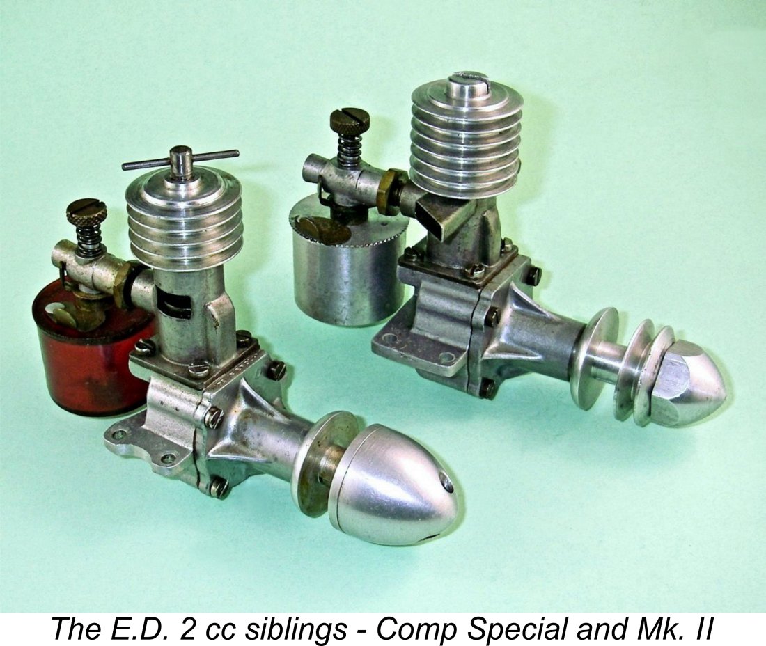 The end of the war and the subsequent release of large numbers of technically-trained individuals both from the armed forces and the wartime industrial complex placed many skilled personnel at something of a loose end in a highly competitive “economic survival” environment. Not surprisingly, a number of them took the entrepreneurial approach by seeking to create their own opportunities through the application of their wartime skills to a "niche" market in which competition might be somewhat less fierce. Some of these individuals were modellers who looked seriously at the model market as a possible commercial outlet for their technical abilities.
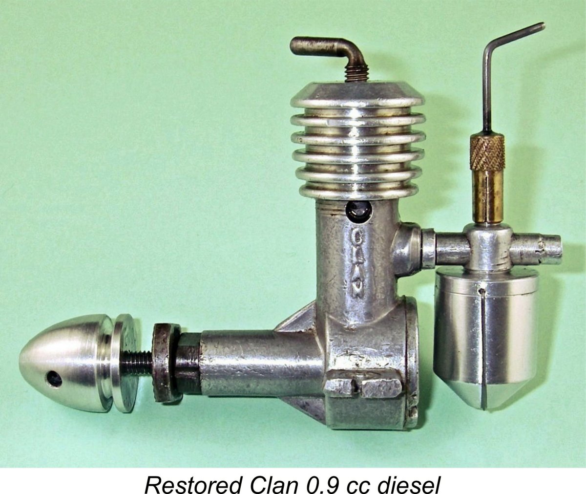 to take control of their own destinies by establishing their own model-related business. The soon-to-be famous E.D. company was the result of their efforts.
 The Milford Mite was a 1.41 cc sideport diesel engine of basically conventional design but displaying some unusual features by the standards of the mid to late 1940's. It was made in relatively small numbers by (or possibly for) a company known as the Milford Gauge Company of 5 Village Way East, Rayners Lane, Harrow, Middlesex (in the North-West sector of Greater London). Production appears to have been confined to the years 1946/48. The engine was evidently the brainchild of a certain Mr. J. R. Smith, about whom very little is known.
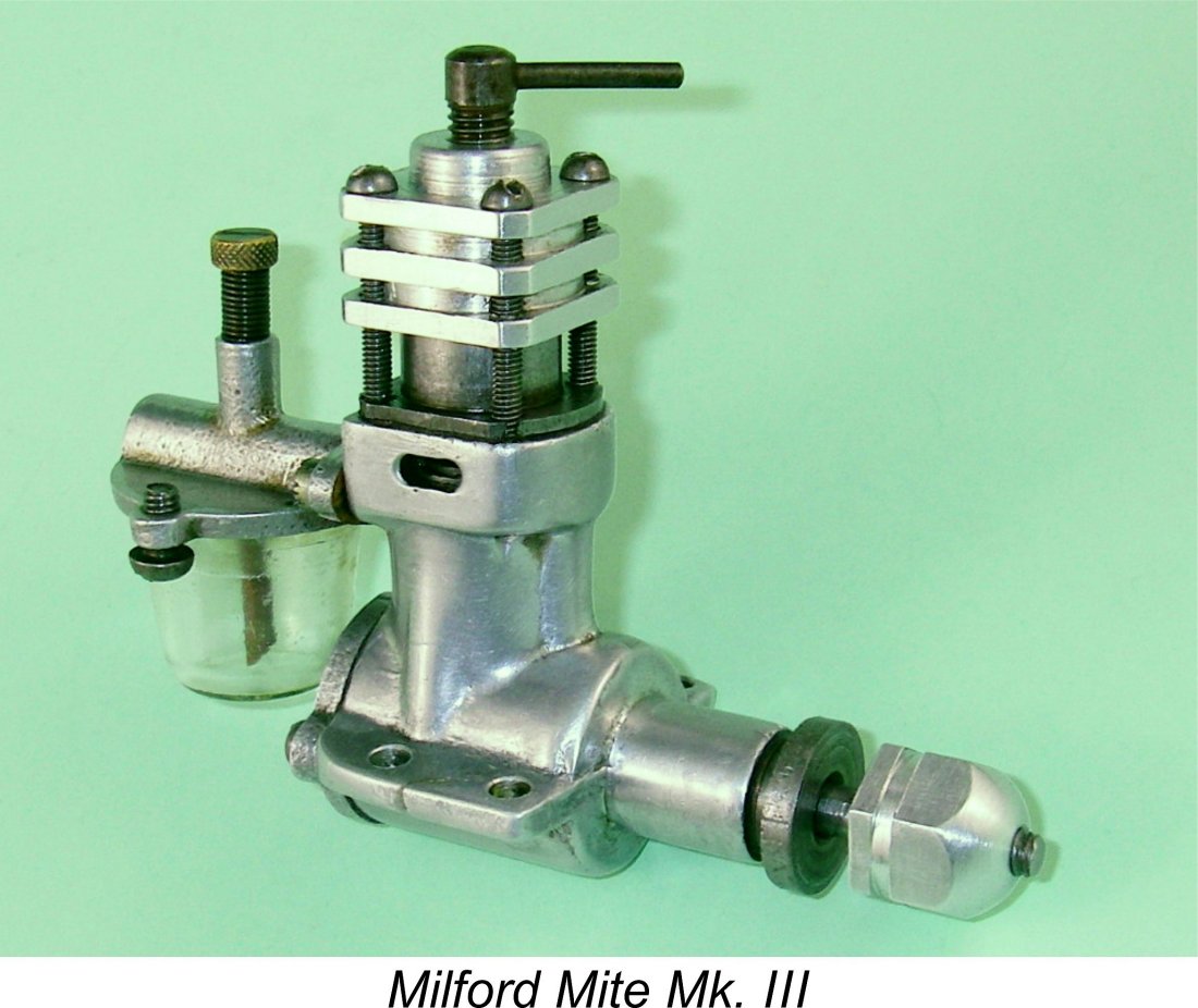 As one would expect from a sideport engine of this vintage, the Mite was a long-stroke engine, although far closer to square dimensions than many other designs of the period. It had a nominal bore of 15/32 in. (0.469in./11.91 mm) and a nominal stroke of ½ in. (0.500 in./12.70 mm) for a stroke/bore ratio of 1.07:1 and a calculated displacement of 1.415 cc (0.086 cuin.). My own Mk. III examples measure up at more or less exactly these figures.
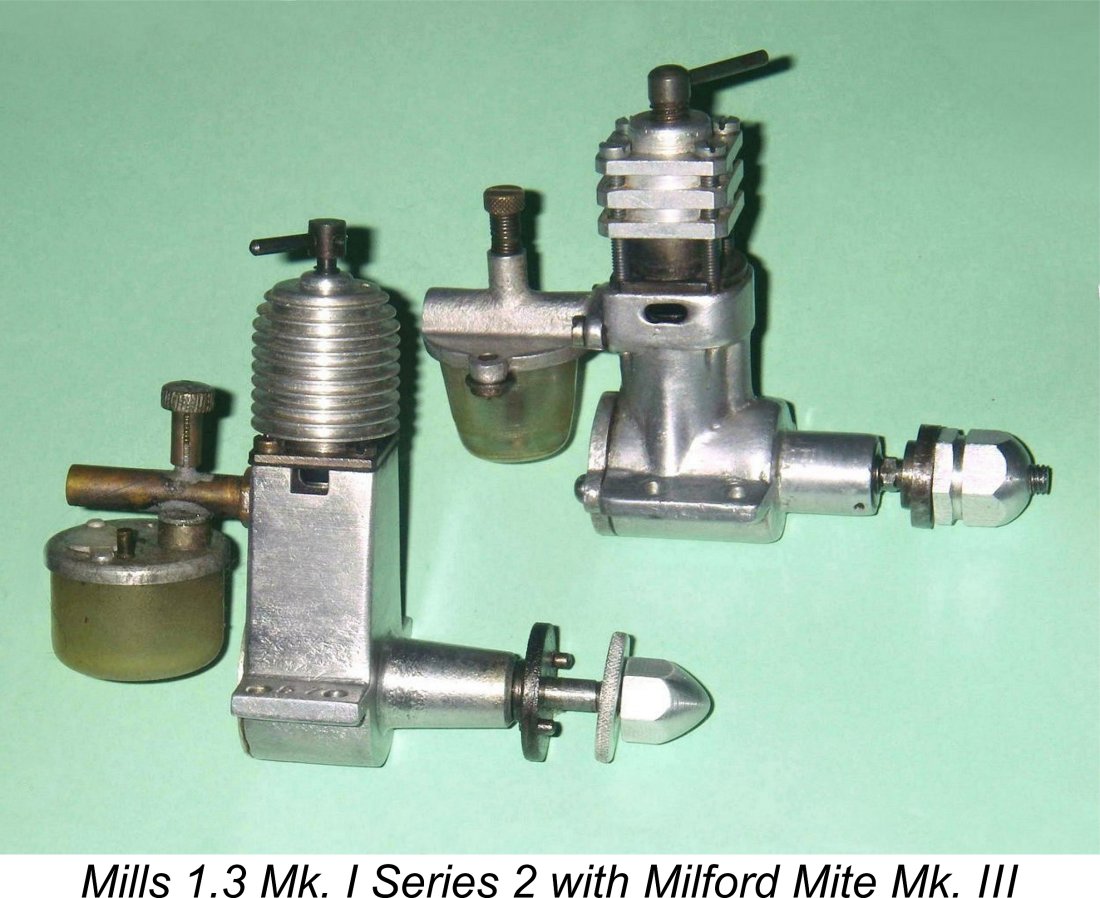 The Mite was made in three distinct variants. The original Mk. I model is pretty much in the unobtanium class in terms of its rarity - I have never encountered an example, either directly or at second hand. However, I do have direct access to examples of both the Mk. II and Mk. III variants. My Mk. II example of the Mite weighs in at a rather hefty 139 gm (4.90 ounces) including the tank. The all-up weight of my Mk. III examples, including tank, is only slight less at 137 gm (4.83 ounces). This is still some 10 gm heavier than the contemporary aluminium case
 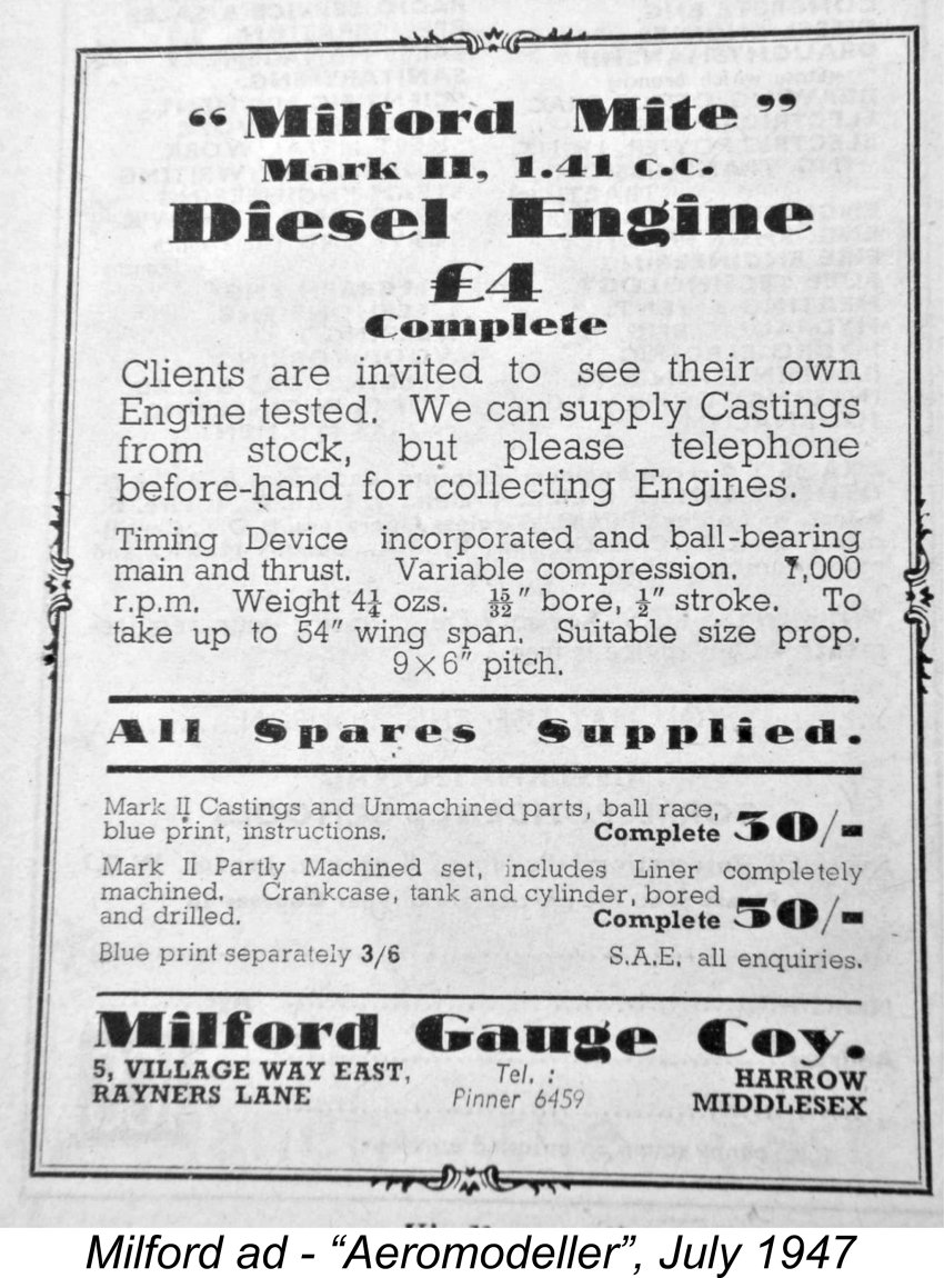 The engine undeniably gives the impression of being one of the "garden shed" products mentioned earlier, evidently having been produced using a rather minimal machine tool inventory along with a fair amount of individual hand-work. This would be entirely consistent with small-scale artisan production and mainly direct distribution. The engine likely represents the efforts of a small group of individuals, presumably led or at least inspired by our mysterious friend Mr. Smith, to earn a little extra money making a simple article that they could sell directly to the public.
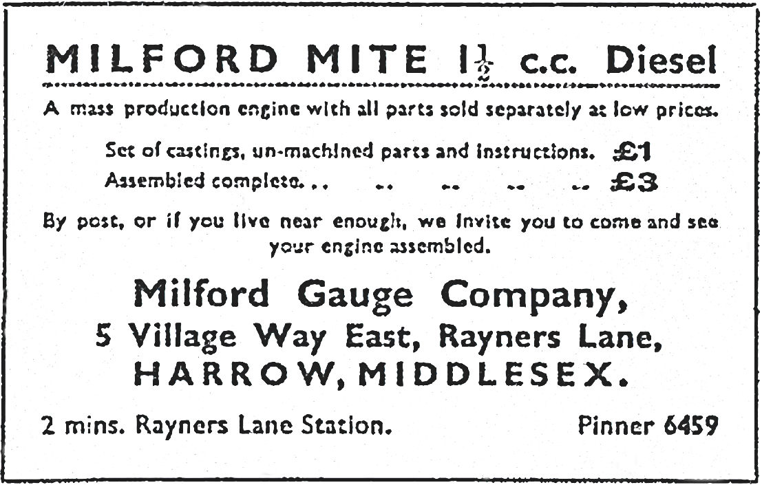
 incontrovertible evidence in the form of manufacturer's advertising to confirm that it is in fact a Mk. III (Wot?!? Clanford wrong again??). Clanford claims on unspecified evidence that very few of these models were made. Based on the scarcity of surviving examples, I'd say that this statement is probably true of all three variants.
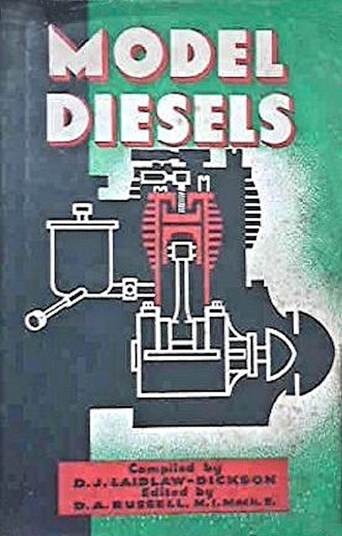 An illustration of this variant appeared in Colonel Bowden's 1947 first edition which was published later in 1947. It was also mentioned and illustrated in the 1947 second edition of Laidlaw-Dickson's book. All of this seems to confirm that the Mite was introduced in early 1947 and that the version illustrated in Col. Bowden's first edition and Laidlaw-Dickson's second edition was the earliest of the three known variants.
 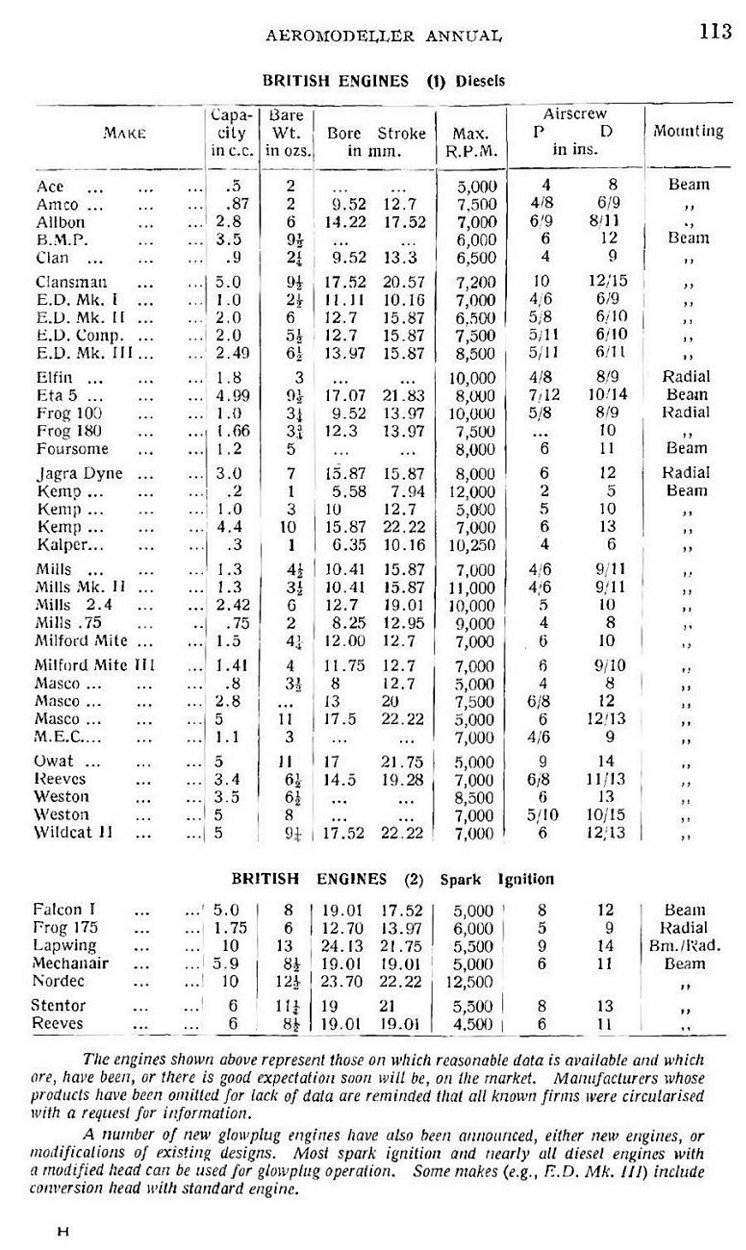 The Milford Mite was also included in the table of British engines featured in the 1948 "Aeromodeller Annual" as reproduced at the left. Oddly enough, two distinct versions of the Mite were mentioned, one identified only as the "Milford Mite" and the other specifically identified as the "Milford Mite Mk. III". Even more strangely, the two variants were cited as having different bores, with reported displacements of 1.5 cc and 1.41 cc respectively.
  It's interesting to note that Warring gave the conrod material for the Milford Mite as being aluminium rather than the actual steel. Just to really confuse matters, he also cited slightly different bore and displacement figures for the Mk. II and Mk. III versions of the Mite. Odd, because the manufacturers made no such distinctions in their advertising! Even more strangely, Warring assigns a larger bore of 0.4657 in. (11.83 mm) to the Mk. III Mite as opposed to the cited 0.4625 in. (11.75 mm) for the Mk. II, but gives a smaller displacement to the Mk. III despite quoting identical stroke measurements! Go figure..............once again, these bore dimensions are inconsistent both with the manufacturer's claims and with my own measurements.
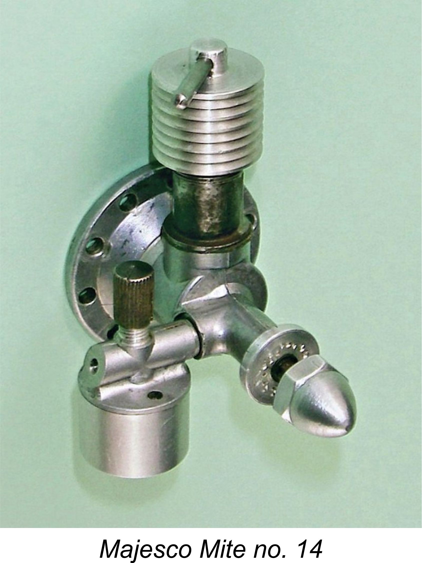
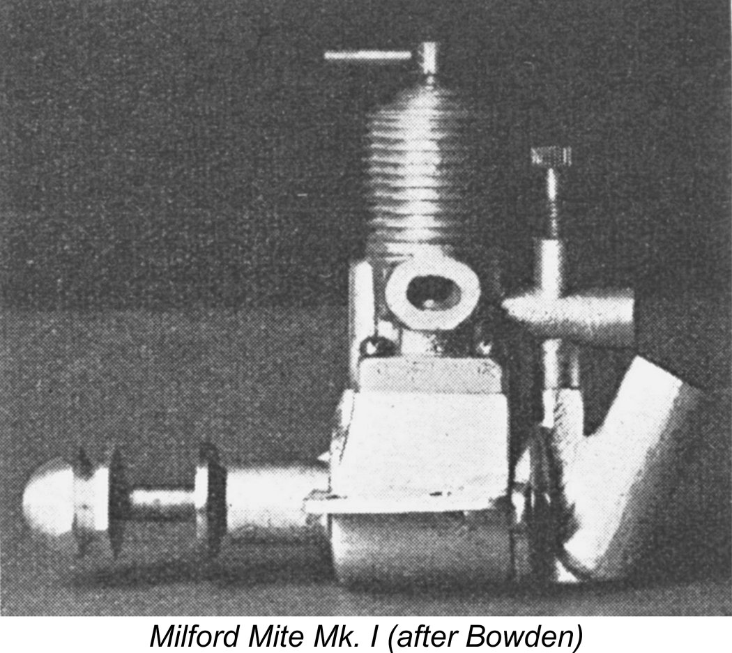 The earliest known variant must surely be the one that appears as figure 40 on page 51 of Colonel Bowden's first edition mentioned earlier, as well as in Laidlaw-Dickson's 1947 second edition. This variant was never advertised, but by reverse extrapolation from the Milford company's later advertising, it appears evident that the makers viewed it as the Mk. I Milford Mite.
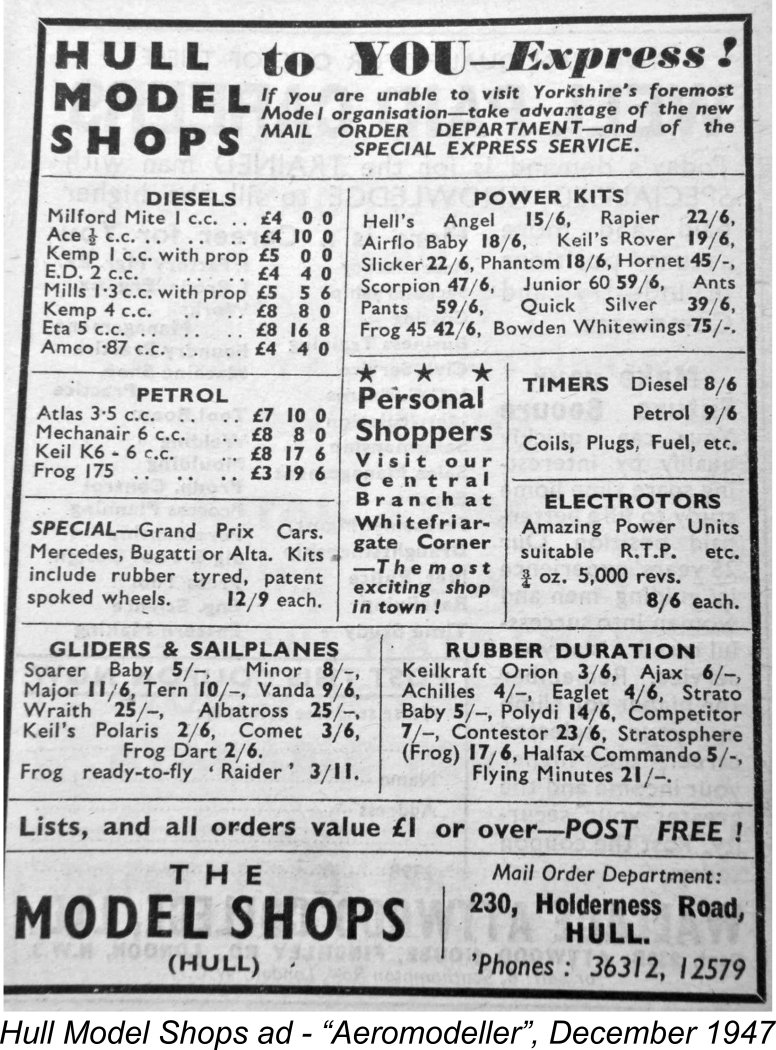
 The liner was presumably inserted into the upper cylinder jacket from below, after which the complete unit was attached to the main crankcase casting by four relatively short screws which bore upon the corners of a flange of square plan view which formed the base of the cylinder jacket casting. The induction tube appears to have been cast integrally with the main upper cylinder jacket. The needle was an externally-threaded item which screwed into an integrally-cast boss in the usual way.
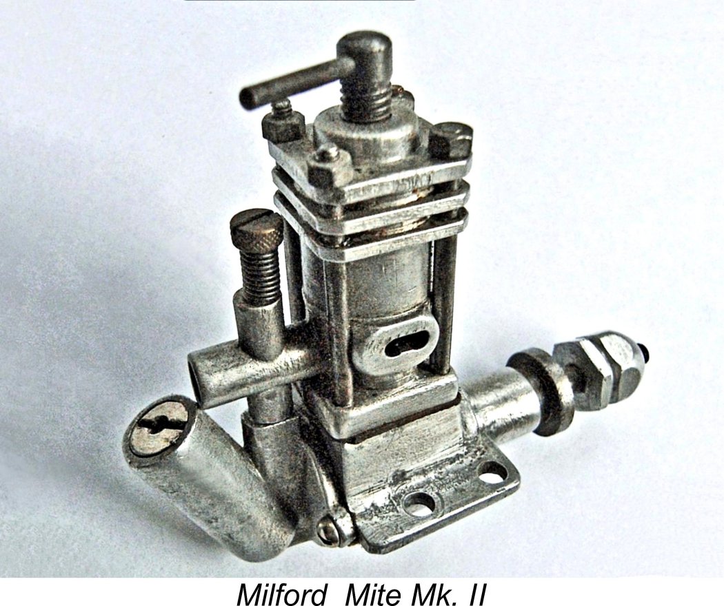 Regardless, the Mk. I version of the engine does not seem to have survived in production for very long - as previously mentioned, by July 1947 the makers were already advertising the Mk. II version of the Mite to be described next. It may be inferred from this that the Mk. I version remained in production for only a few months at most.
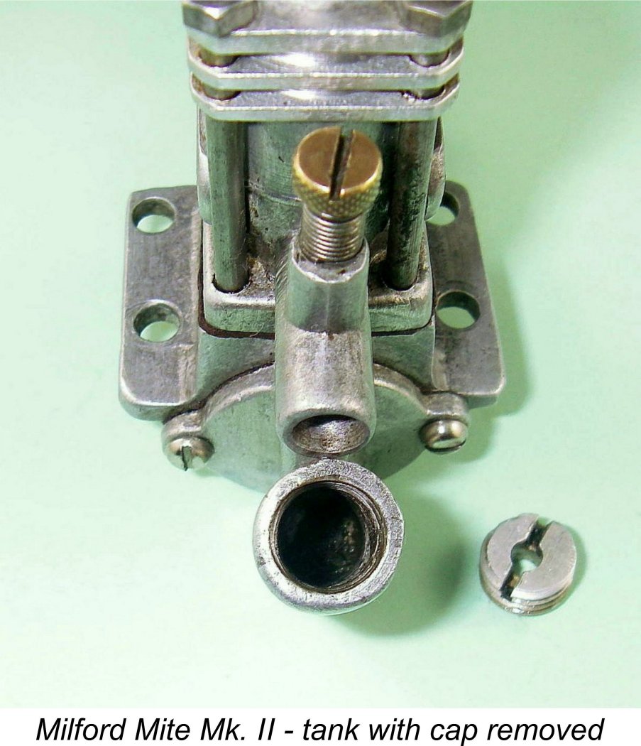 One feature which will be clarified by reference to the accompanying image is the fuel tank timing device mentioned by Col. Bowden in connection with the Mk. I version of the Mite. This device seems to have been carried over directly from the Mk. I to the Mk. II. It consisted of an externally threaded plug which screwed into the tapped interior of the cylindrical fuel tank and had a filler hole at its centre. By screwing this more or less into the tank, one could in effect vary the tank's fuel capacity and hence the approximate length of the expected motor run. I can't personally recall another instance of the provision of a fuel tank of variable capacity - ingenious, if a little imprecise!
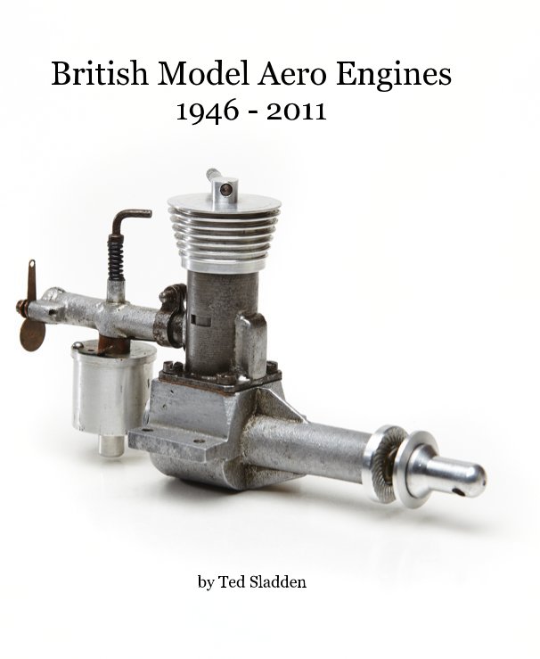 Alternatively, a tankless backplate from a Mk. III model could be fitted. Either way, the fuel pickup tube was exposed, allowing the use of a separate fuel tank.
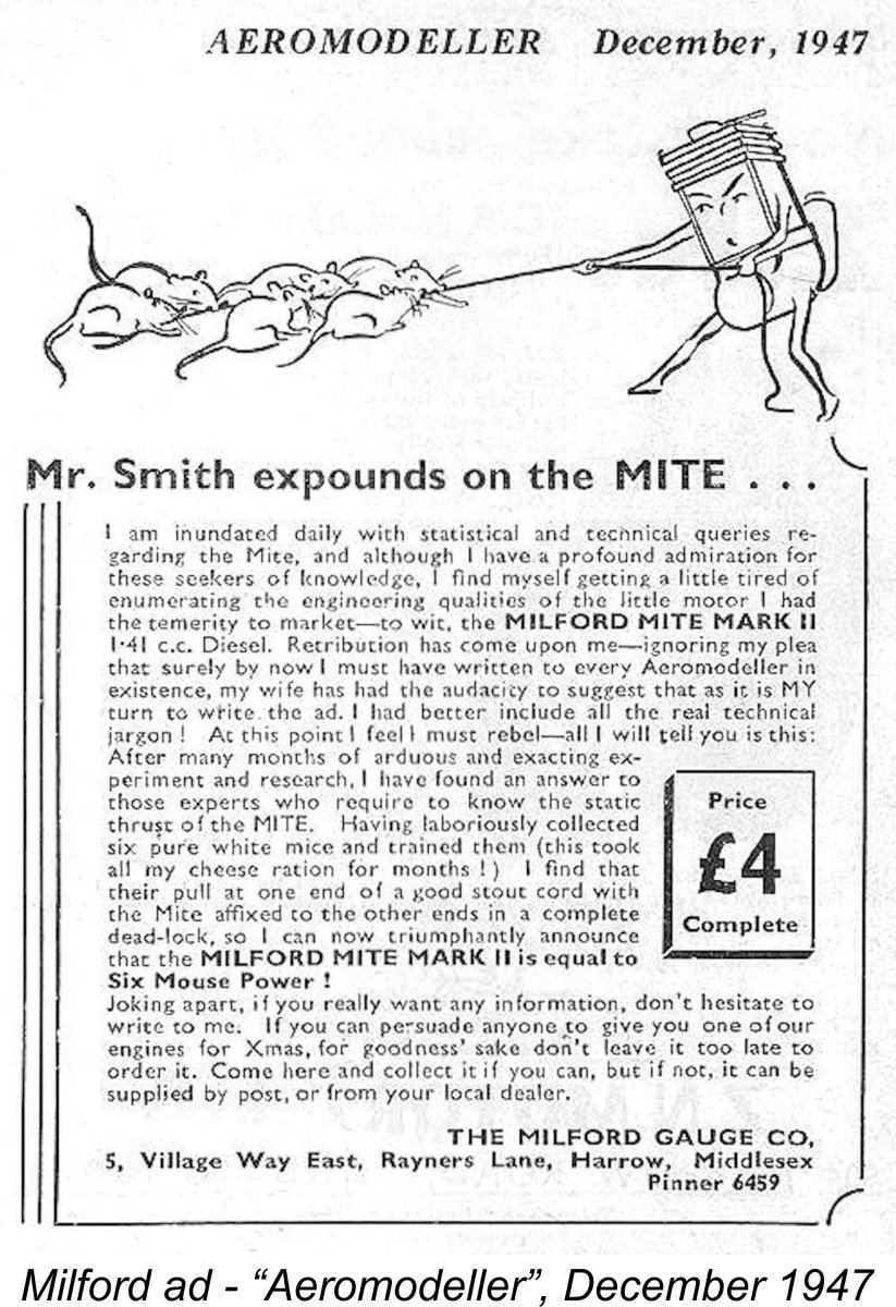 The previously-mentioned advertisement from the December 1947 issue of "Aeromodeller" which appeared directly above the Hull Model Shops placement confirms that this version of the Mite was still on offer as of December 1947. The copywriter was evidently the elusive Mr. Smith, who certainly had a chatty and amusing style! It seems that his wife had been writing some of the advertising copy but had decided that it was his turn and that he should impart some useful technical information. Nothing loath, Mr. Smith proceeded to demonstrate in most amusing terms the fact that the Mite produced an output of 6 MP (Mouse Power)!! I think that I would have got along with this chap, preferably over a pint or two!
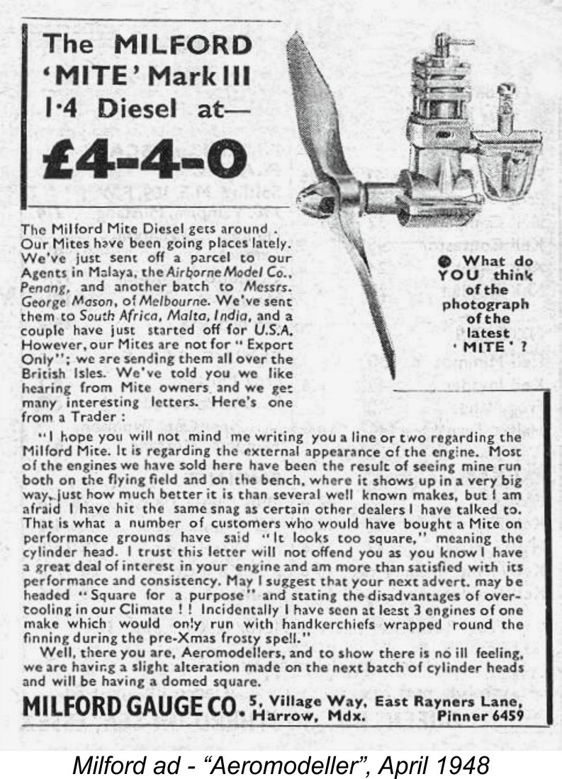 There's no doubt at all that this version of the engine was in production as of February 1948, since an advertisement was placed in the April 1948 issue of "Aeromodeller", which actually hit the newsstands in Mid-March. In this advertisement, the makers cited recent overseas shipments to such exotic locations as Australia, the USA, Malaya, South Africa, India and even Malta! It was undoubtedly true that the Mite had been getting around - that same April 1948 issue of the magazine carried advertisements from Jones Bros. of Chiswick and Modelcrafts of Falkirk, Scotland in which the Mite was among the engines on offer. The Jones Bros. placement referred specifically to the Milford Mite Mk. III.
 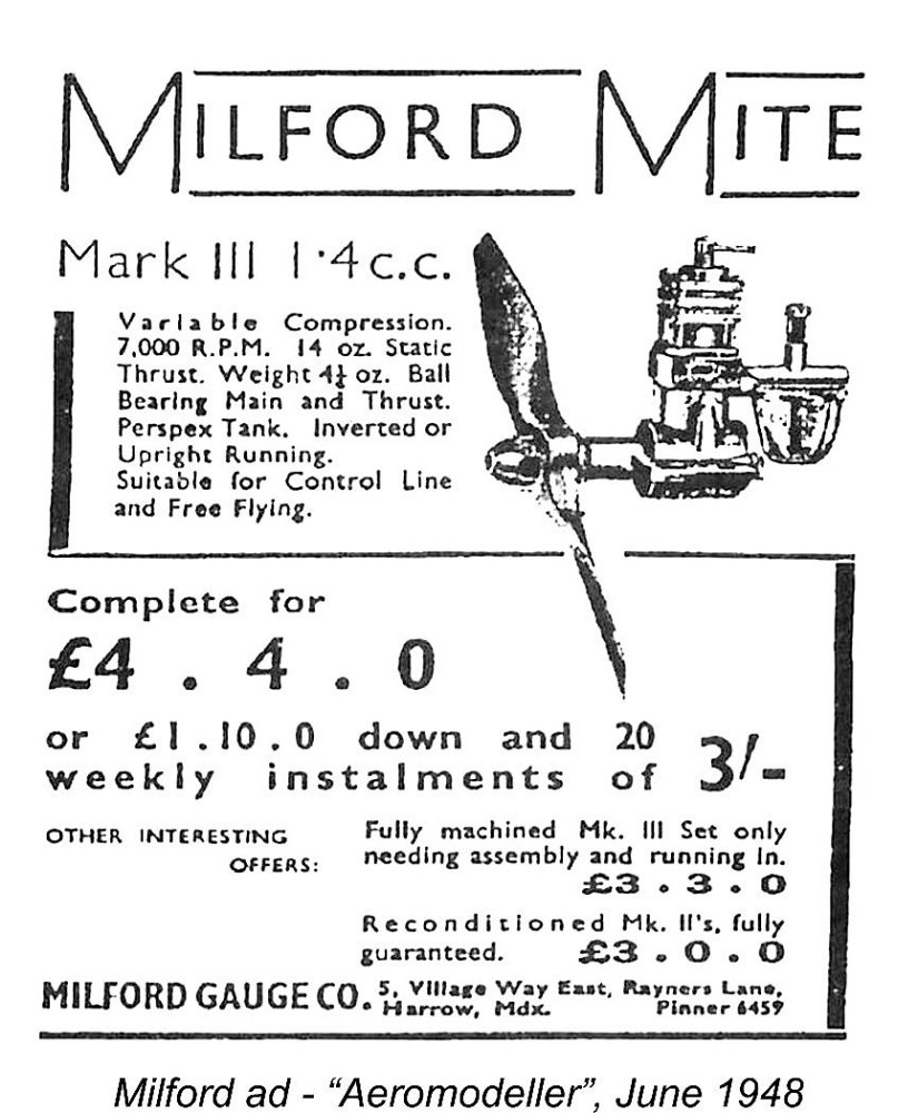 The price of the Mite Mk. III was unchanged at £4 4s 0d (£4.20) but for the first time, the engine was now available on the hire purchase scheme. A down payment of £1 10s 0d (£1.50) allowed the customer to take possession of his engine, after which he was required to make twenty weekly payments of a princely 3s 0d (15p) to complete the purchase. Thus the customer ended up paying a total of £4 10s 0d (£4.50) under this scheme - a credit premium of 6s 0d (30p) over the twenty week period. This translates into an interest rate of 6.66% payable for the 20-week period. Nice work if you can get it!
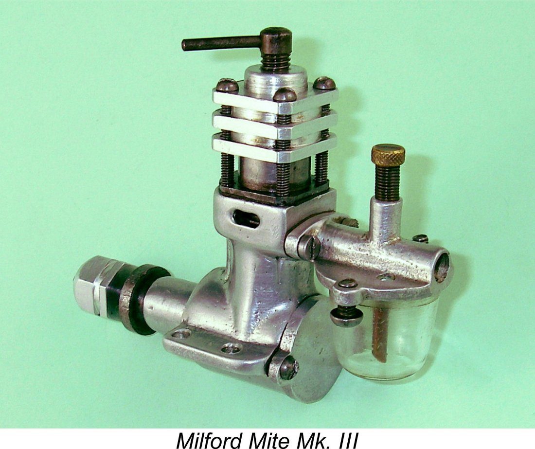
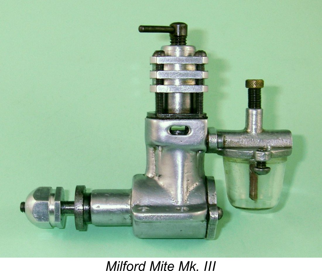 For starters, the crankcase casting was substantially revised. It now extended up above the exhaust location and included both the exhaust passages and the carburettor mounting flange. This flange accommodated a completely new bolt-on carburettor body which incorporated the tank top in unit. The former stubby exhaust stacks were eliminated in favour of a simple pair of slots. As before, a single bypass passage was formed at the front of the casting in the conventional location for a sideport engine. The casting was apparently finished by brushing.
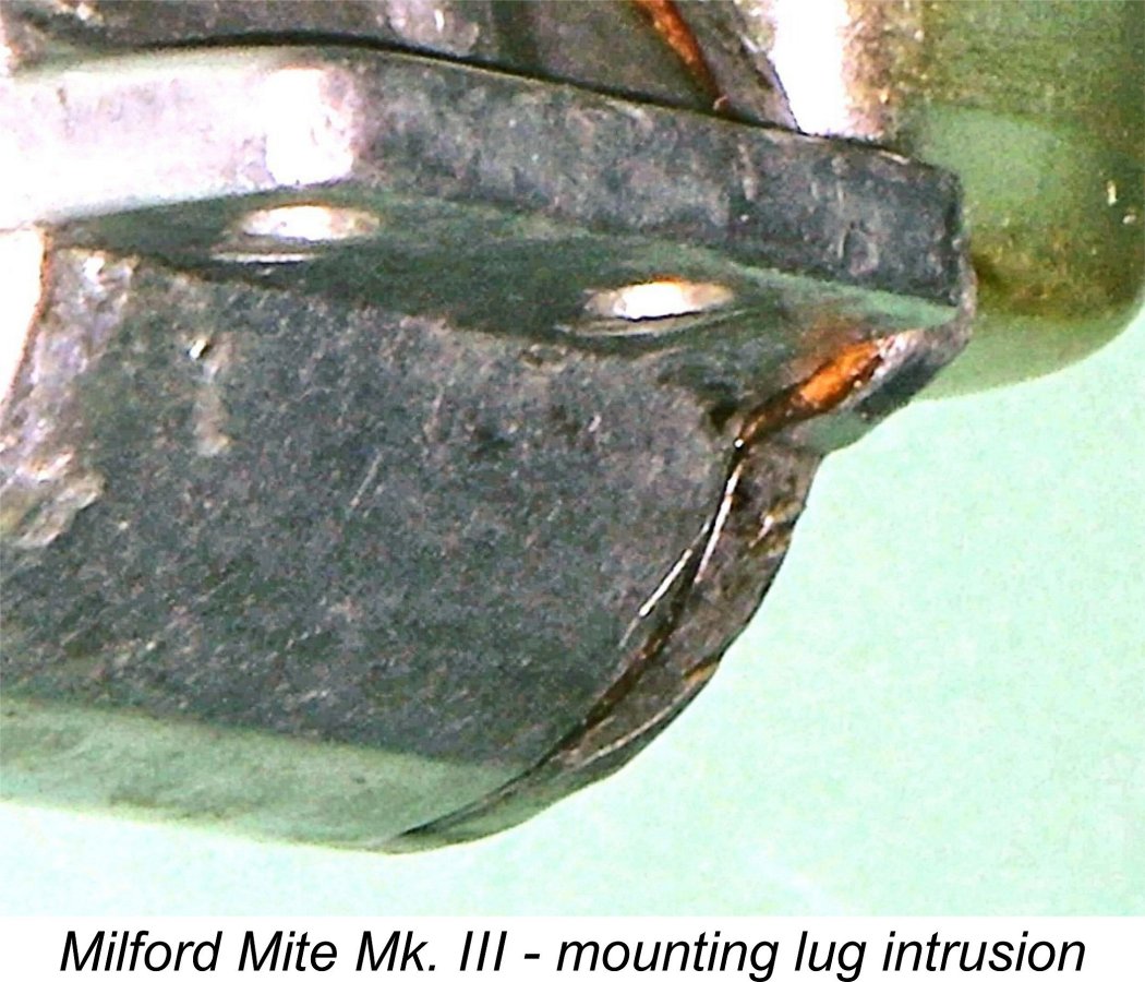 There was however a fly in the above ointment which applied to all variants of the Mite. The rear of the mounting lugs had to accommodate the tapped holes for the two screws that retained the backplate. The designer elected to create a slight expansion of the lug thickness at the rear. While this increased its thickness over that of the Mk. II model, it was still rather marginal for tapping. This would have been a good idea were it not for the fact that the lower portions of the thickened sections naturally extended below the plane of the mounting surfaces and required that the bearers in the model be slightly recessed to accommodate the twin "bulges".
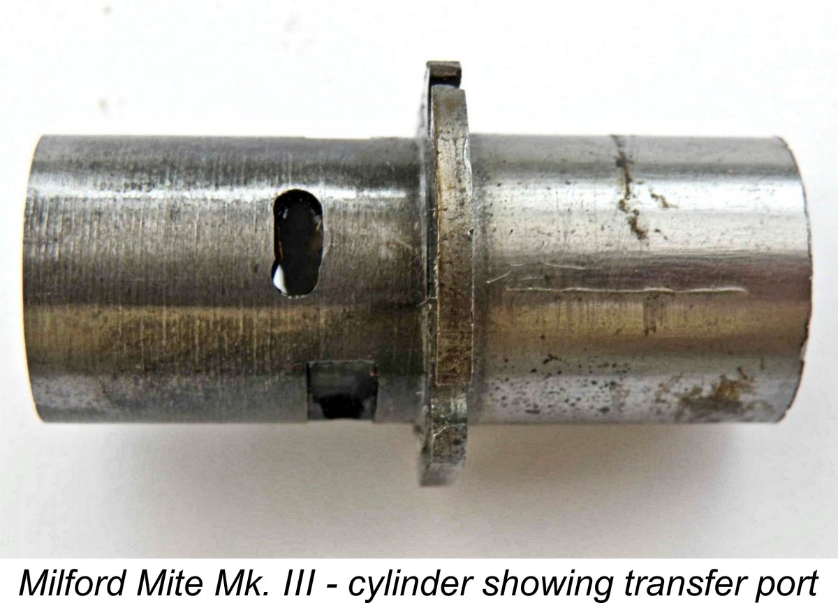 substantial increase in the thickness of the front wall of the crankcase itself. Combined with the facts that the relatively thick-walled bushing itself doubtless added greatly to the strength of the bearing and the rear of the shaft was of course very well supported by the ball race and the strengthened crankcase casting, this was likely an adequate response to the strength issue.
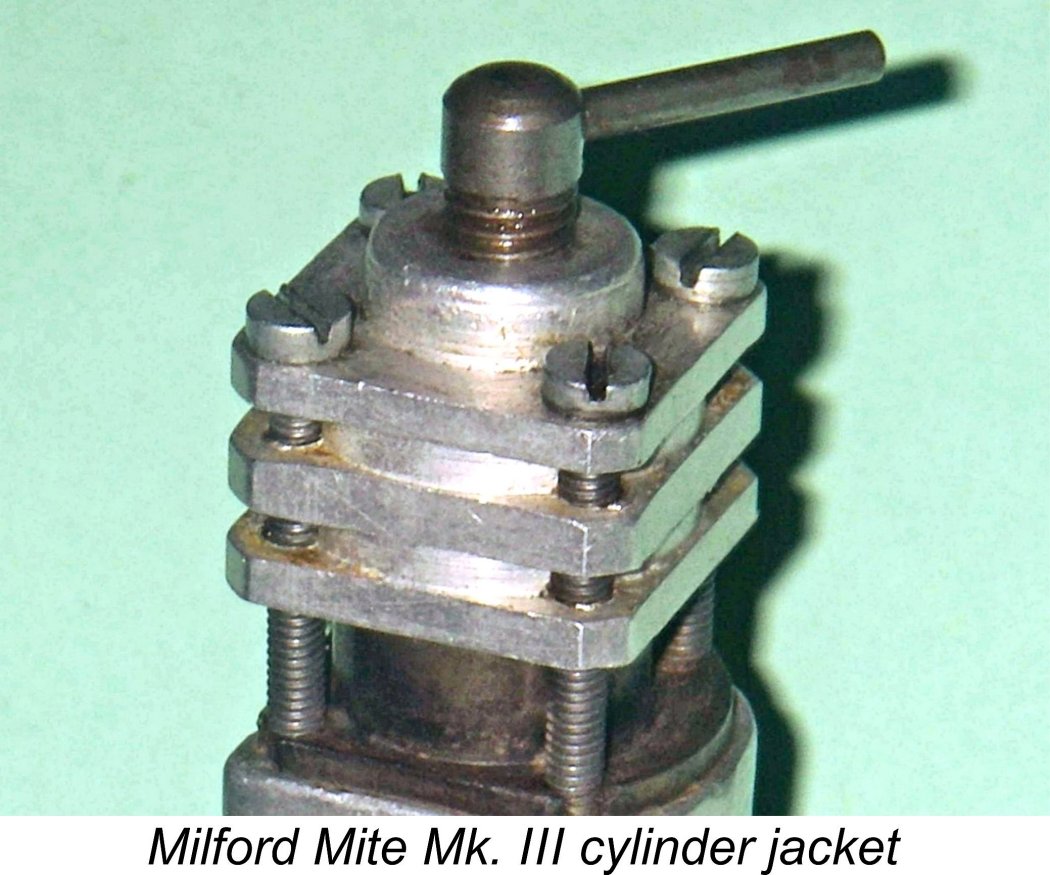 Another very significant change was the form of cylinder jacket used. The full-length cast jacket was replaced by a far shorter machined jacket located at the top of the cylinder, leaving most of the working length of the cylinder exposed with no cooling provisions, exactly as in the contemporary
 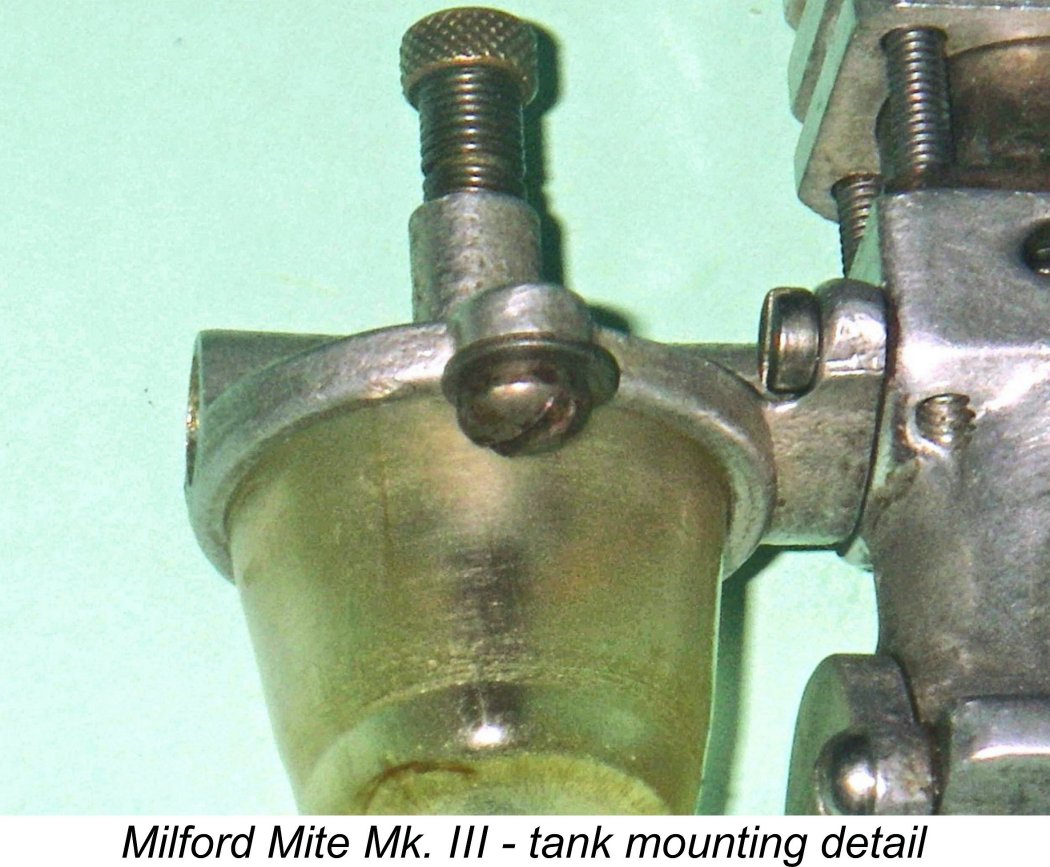 A conventional moulded plastic tank was mounted beneath the cast tank top, being retained at the sides by a pair of screws with washers having flats filed on one side. These functioned as wedges to hold the tank in place. The arrangement seems a little sketchy at first glance, but in fact the tank stays put in use with no problems. Unusually by the standards of the day, there was no provision for a fuel cut-off on this model.
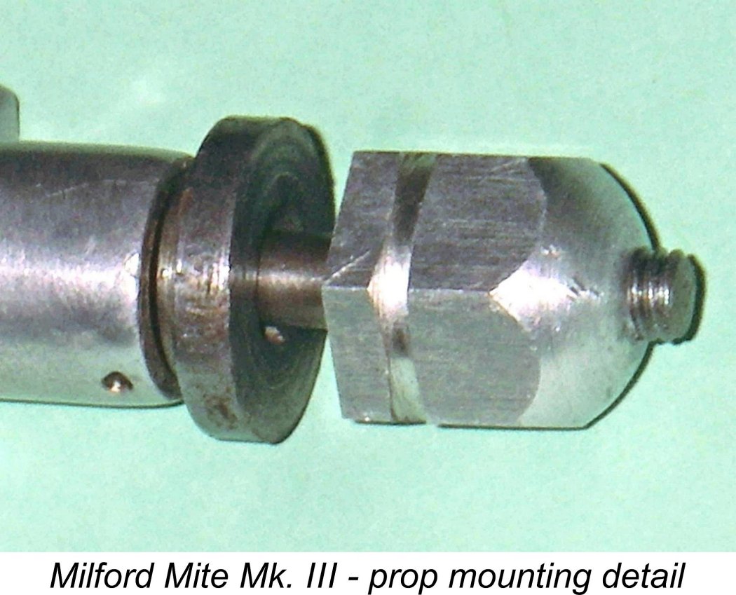 Finally, the prop mounting arrangements appeared to be unchanged from the earlier variants. The steel prop driver had a square opening at the centre which located onto a square section machined into the shaft just forward of the main bearing. The assembly was completed by a neatly-made spinner nut turned from hexagonal bar stock.
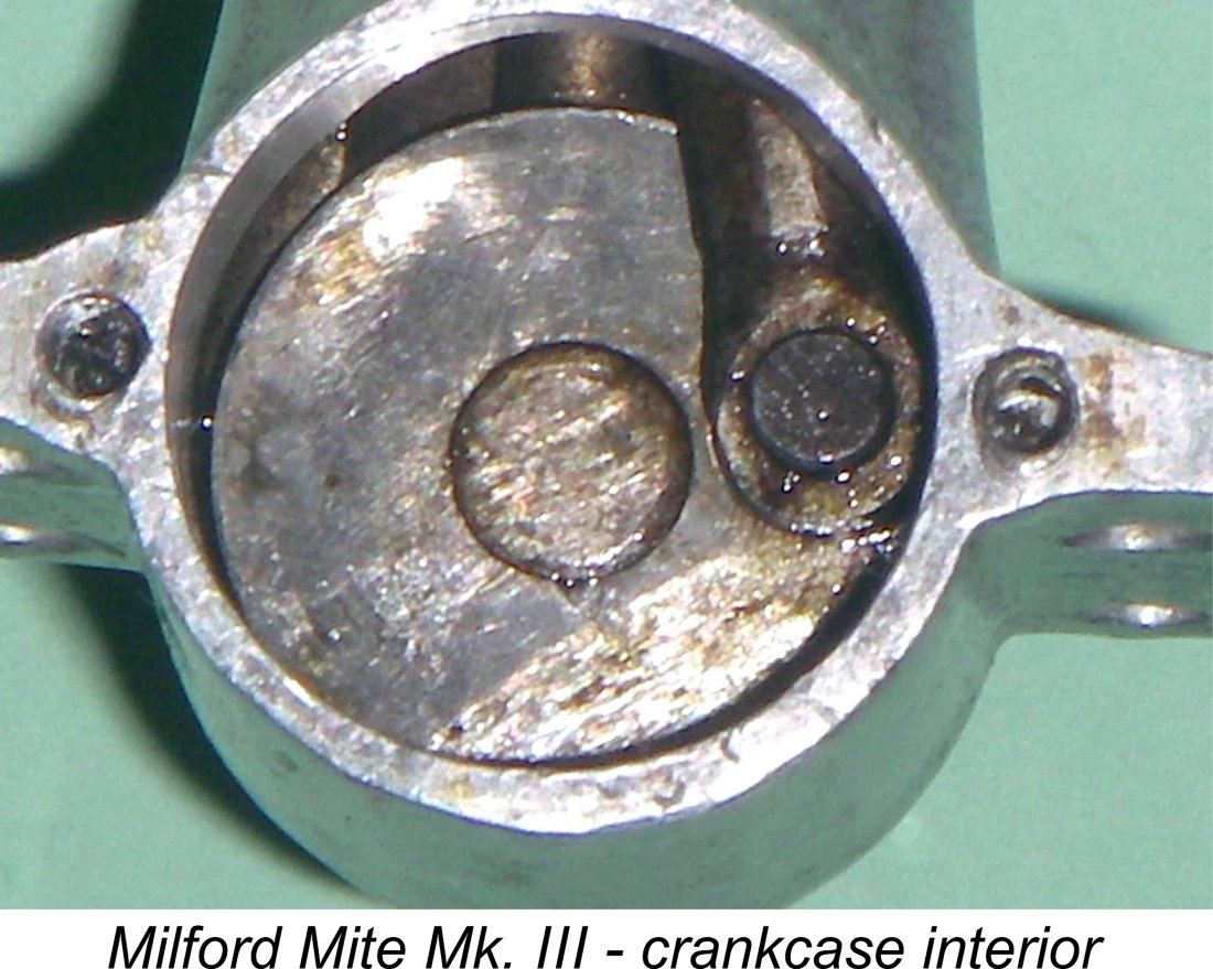 For starters, the crankshaft proved to be a built-up item consisting of a separate crankweb of plain disc form (no counterbalance) which is mated to the nominally ¼ in. diameter shaft. Kevin Richards was kind enough to take his Mk. III example apart a bit further, and this revealed that the shaft is actually made up of three separate components - main shaft, crank-disc and crankpin. The crankpin is pressed into a hole in the crank disc, which is made very thick to provide good support. The crank-disc is retained in position on the main shaft by means of a transverse pin installed in a cross-drilled hole passing through both components. The obvious disadvantage is that there will be a tendency for a "wobble" to develop between the main journal and the transverse pin unless an interference fit is established at the outset and subsequently maintained.
 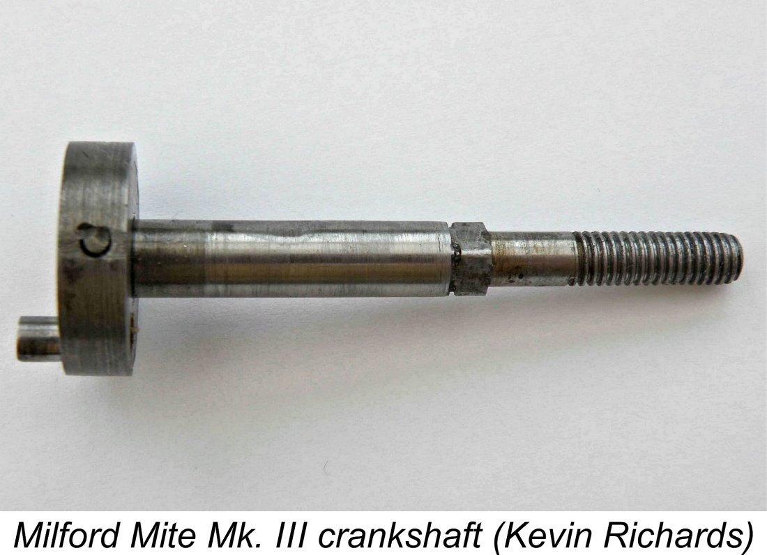 This form of composite construction was by no means unique - the British
 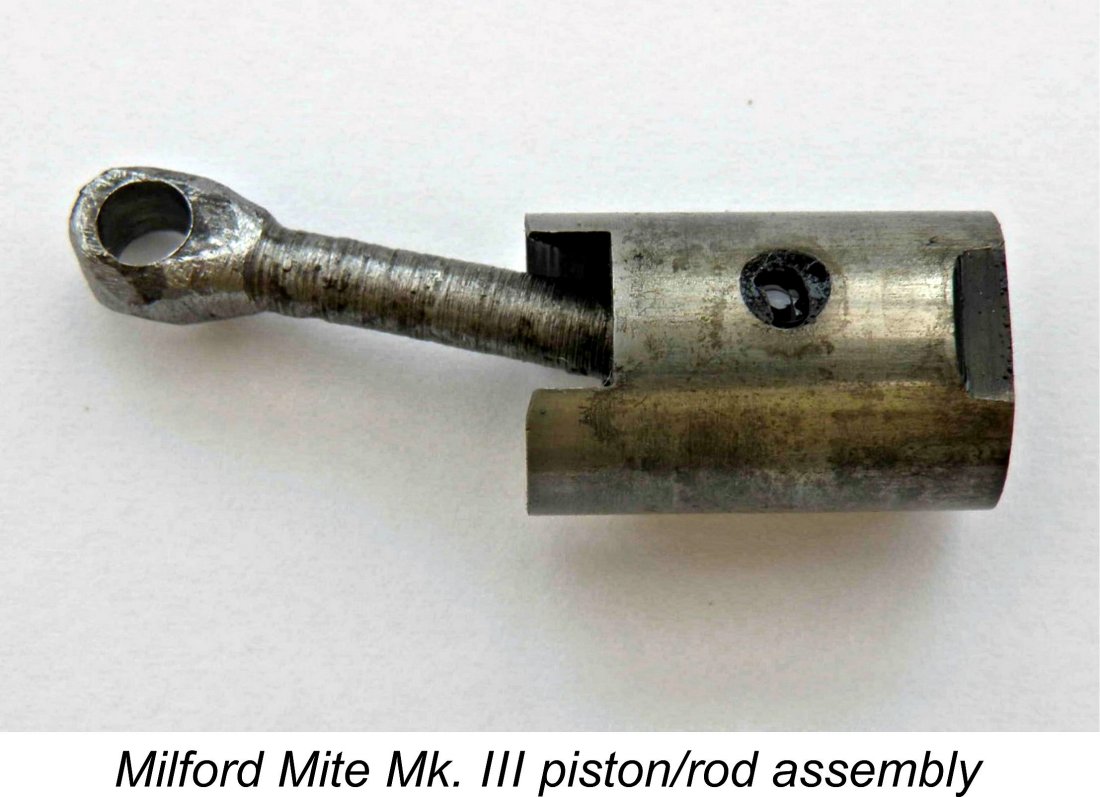 Again, Kevin was able to supply an image of the piston-rod assembly from his example. This shows that the rod in that instance is somewhat roughly turned rather than hand-filed. Perhaps one or the other is a home-built example?? Impossible to say which is which, if so!
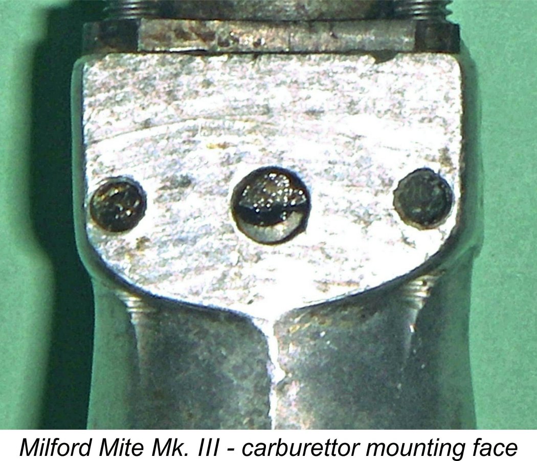 Turning to the fuel supply side, the induction port in the cylinder wall is similar in shape to the transfer port and has a relatively generous area. Indeed, as an overall comment it's fair to say that the porting arrangements in the Mite appear throughout to be more than adequate for the job. The induction port is supplied with mixture through a 0.147 in. (3.73 mm) diameter round hole drilled through the flat surface provided at the rear for mounting the carburettor assembly. Two tapped holes are provided in this surface at the sides to accept the 6BA screws which retain the assembly. A paper gasket is used to seal. There is no supplementary sub-piston induction.
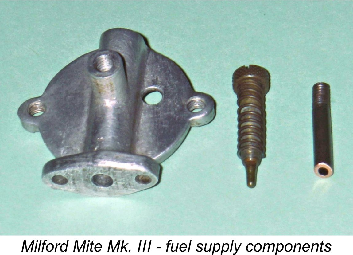
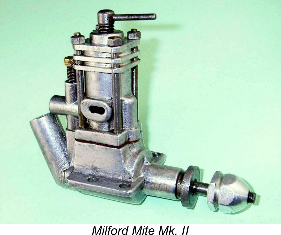 little slop in the rod bearings, but both engines have undoubtedly been mounted and used (Wot?!? Mites getting used?!?) and the small amount of detectable play is consistent with incidental wear arising from normal operation.
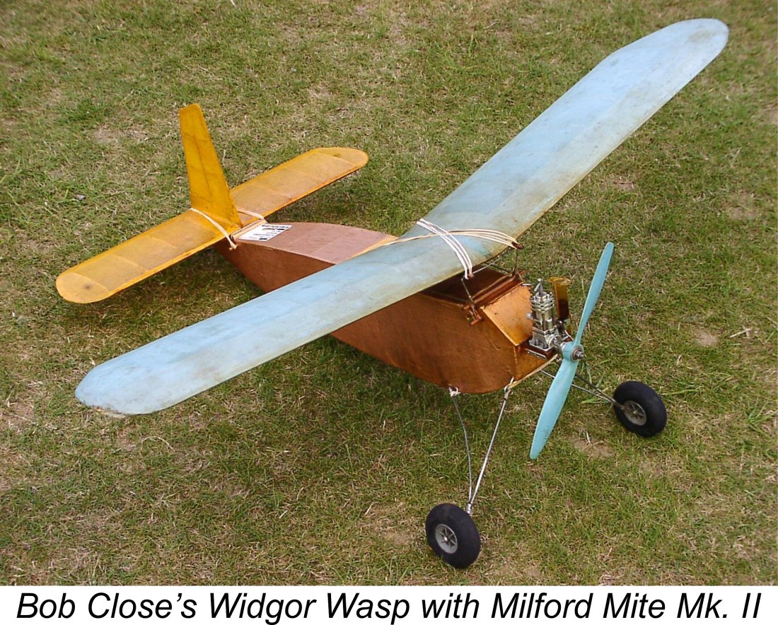 upon it over the years! It may look a little rough, also embodying a few questionable design features such as the composite crankshaft, but its quality where it counts is quite adequate if not exactly outstanding. However, I'm personally able to comment on this issue on the basis of only three examples, and it's certainly true that one cannot draw any truly authoritative conclusions on such a basis. Perhaps I’ve just been lucky …………..
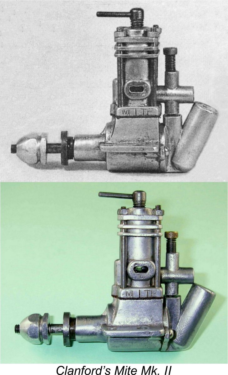 I initially thought that the existence of my own and Clanford's fully functional examples of the Mk. II Mite along with Bob Close’s example constituted proof positive that there were at least three confirmed serviceable examples on record. However, a tracing of its ownership history has confirmed that the Mk. II Mite which I now own is the actual engine illustrated in Clanford's book! It had been purchased from Clanford by another collector and was subsequently acquired from the latter by none other than my mate Kevin Richards! From there, it passed into the hands of Mel Reid and thence to me. Apart from the confirmed ownership history, a number of clearly visible incidental markings as well as the imperfections in the strike of the "MITE" identification on the crankcase put the engine's individual identity beyond doubt.
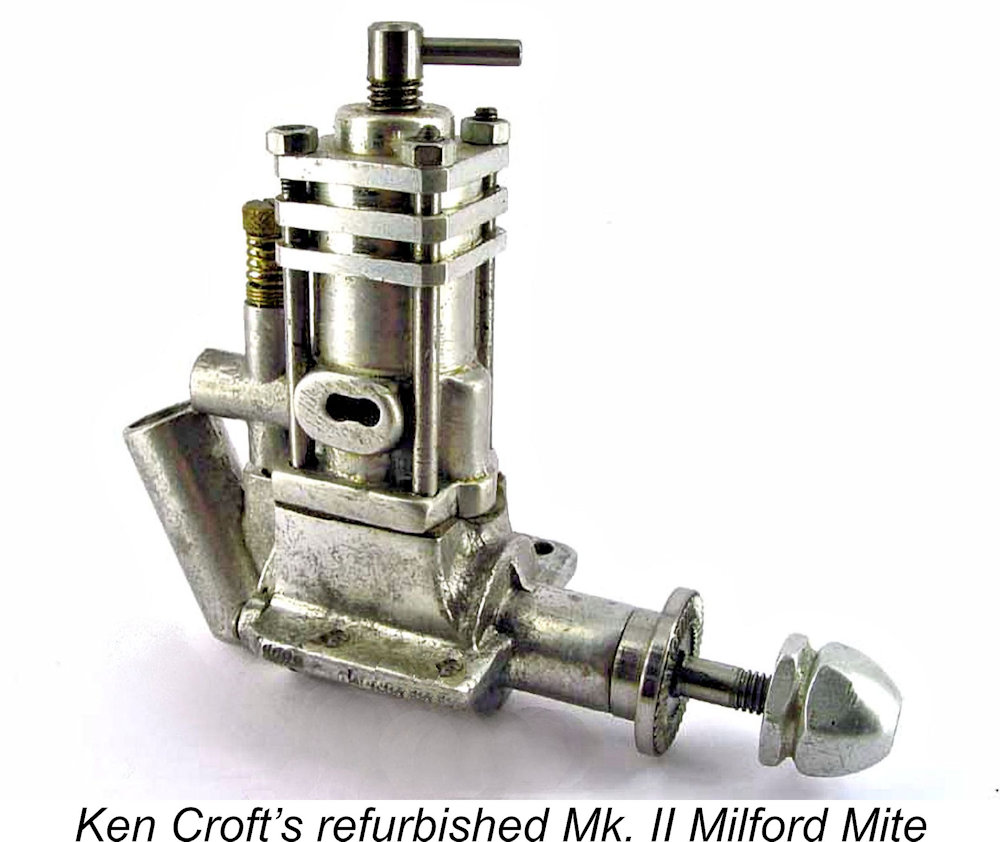 It thus seems certain that least some examples of this much-maligned engine were sufficiently well made to have potentially given good service. That said, the sorry reputation of the Mite and its very short production period combine to suggest that many examples did not come up to the required standard. There must surely be some basis for the long-standing legend of the Mite's shortcomings!
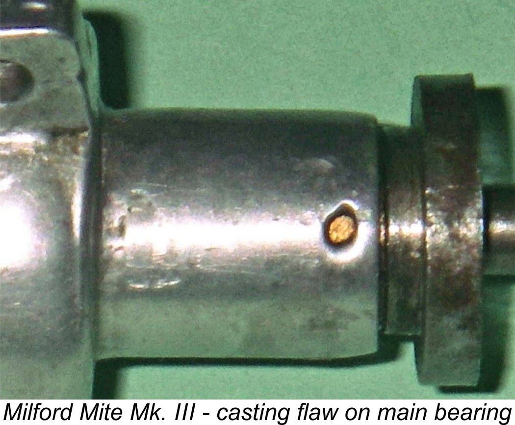 be well capable of giving good service - only the best escaped the rubbish tip!! In other words, the average quality of the surviving examples may be considerably better than the overall average at the time of manufacture, whether by the company or by their customers.
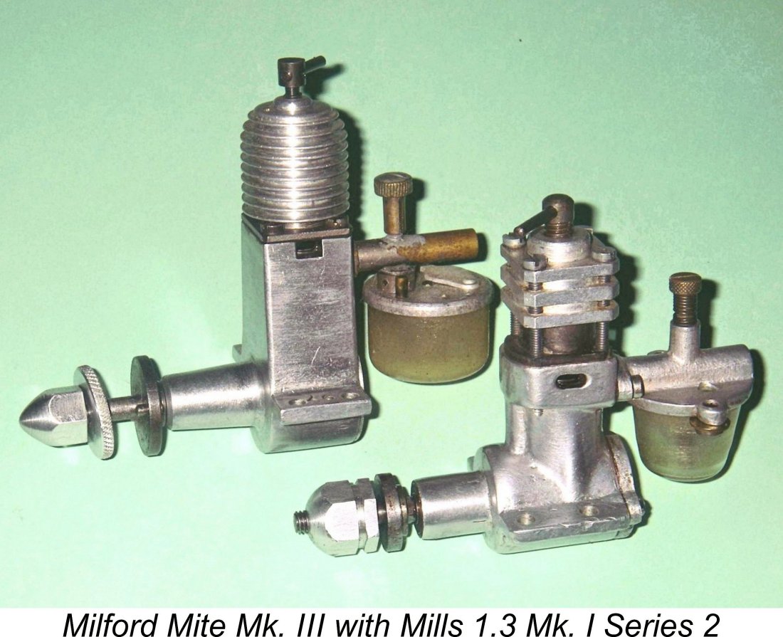 I'll begin this section of the revised article by reviewing the results of my original testing of the Mk. III Mite prior to the publication of my original 2009 article on MEN. The sole example of the Mk. III Mite which I owned at the time had clearly had a fair bit of previous use, although as stated above it remained very well fitted where it counted.
 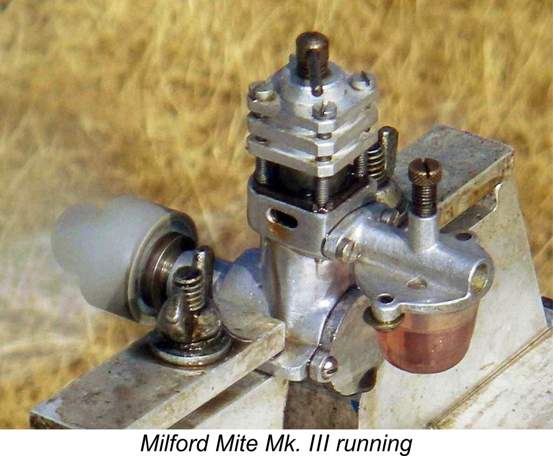 Taking the Mite's displacement, design configuration and reputation into account, I wasn’t expecting much in the way of high-speed performance. Accordingly, I elected to begin with a 9x4 prop just to see how the land lay. I guessed the needle setting, left the compression as set, filled the tank, gave it two choked flicks and was ready for the off.
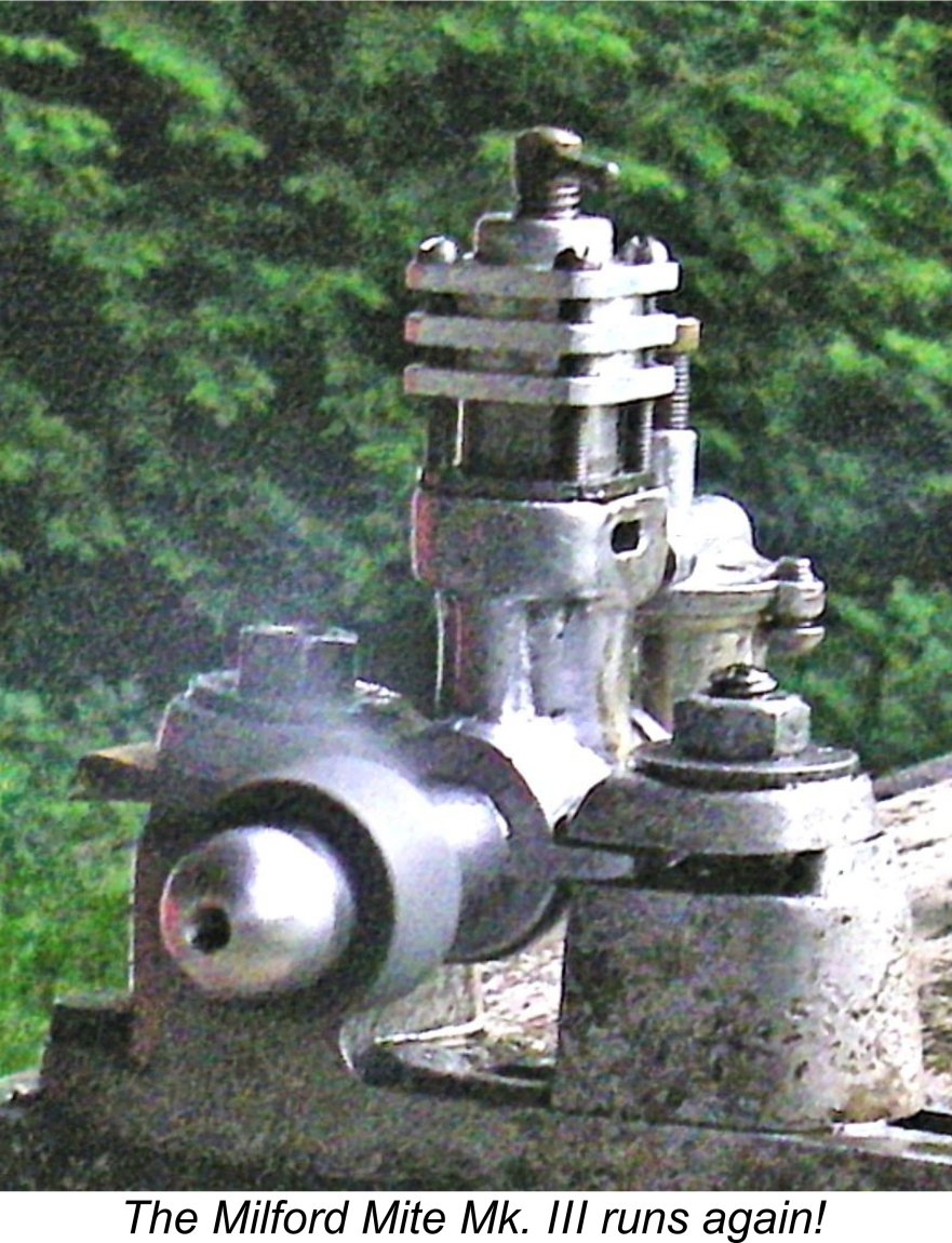 Greatly encouraged, I proceeded to test a series of props that should in theory cover the available speed range. Starting remained foolproof, no prime being required at any time. In deference to its age and rarity I didn't press the engine unduly, keeping it very slightly rich and under-compressed apart from a brief leaned-out period to establish the best speed for each prop. It must be said that the results achieved were by no means unflattering to the little Mite.
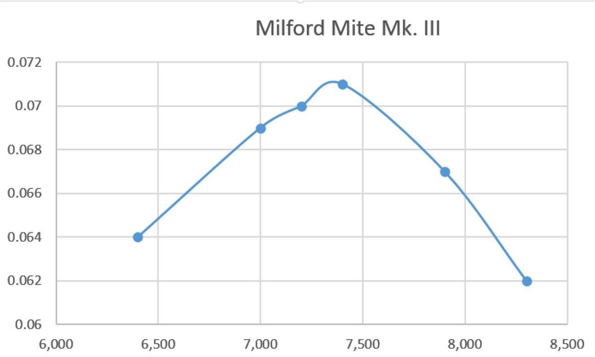
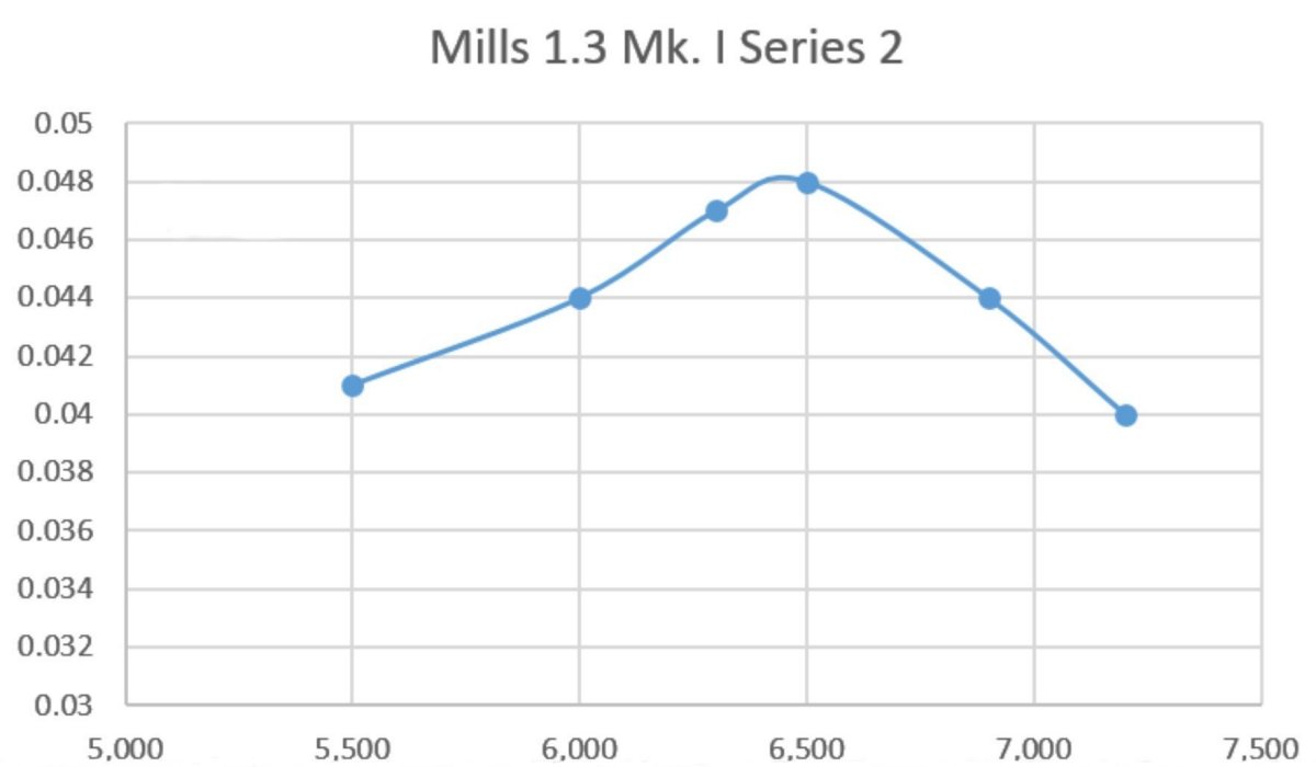
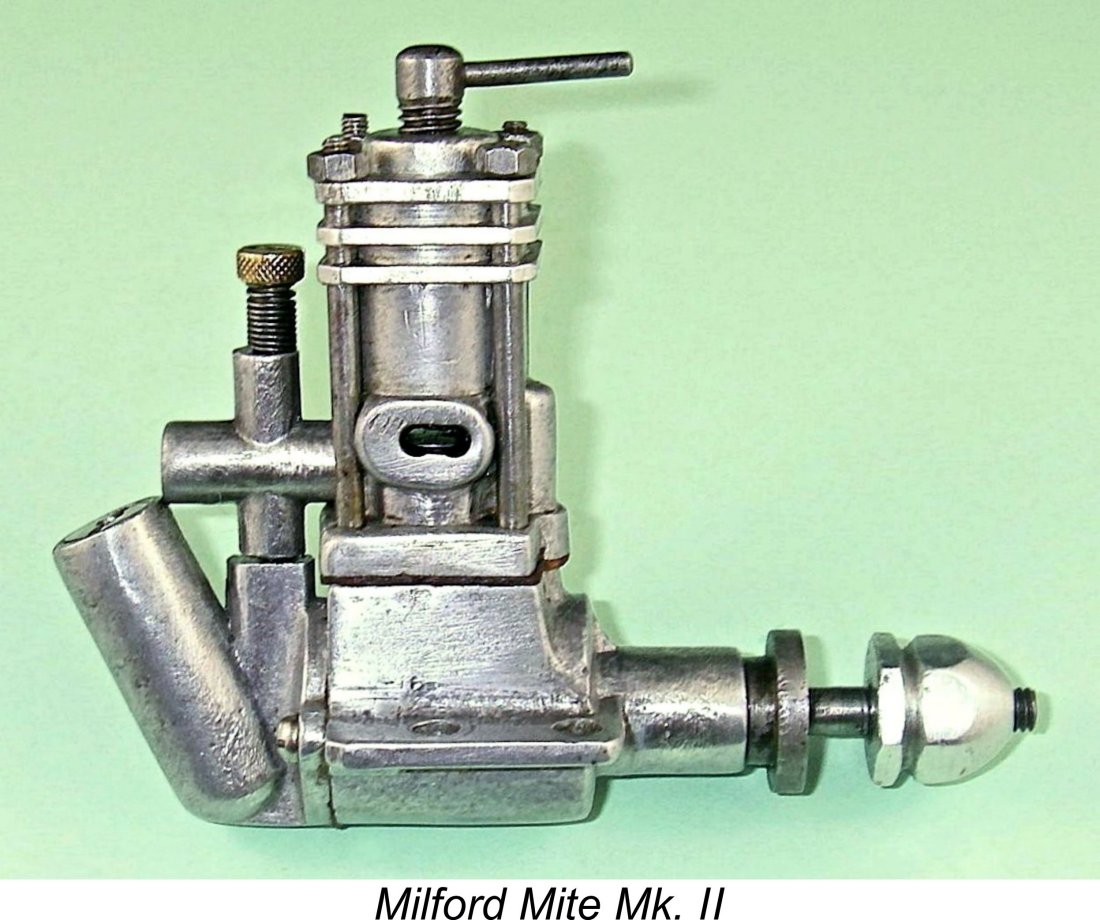 Happily, Dame Fortune wasn’t done with me yet! As previously noted, I was subsequently able to acquire the ex-Clanford Mk. II Milford Mite. Consequently, I had the opportunity to subject that model to a repeat of my tests on the Mk. III Mite and the Mills using the exact same airscrews from my APC test set.
 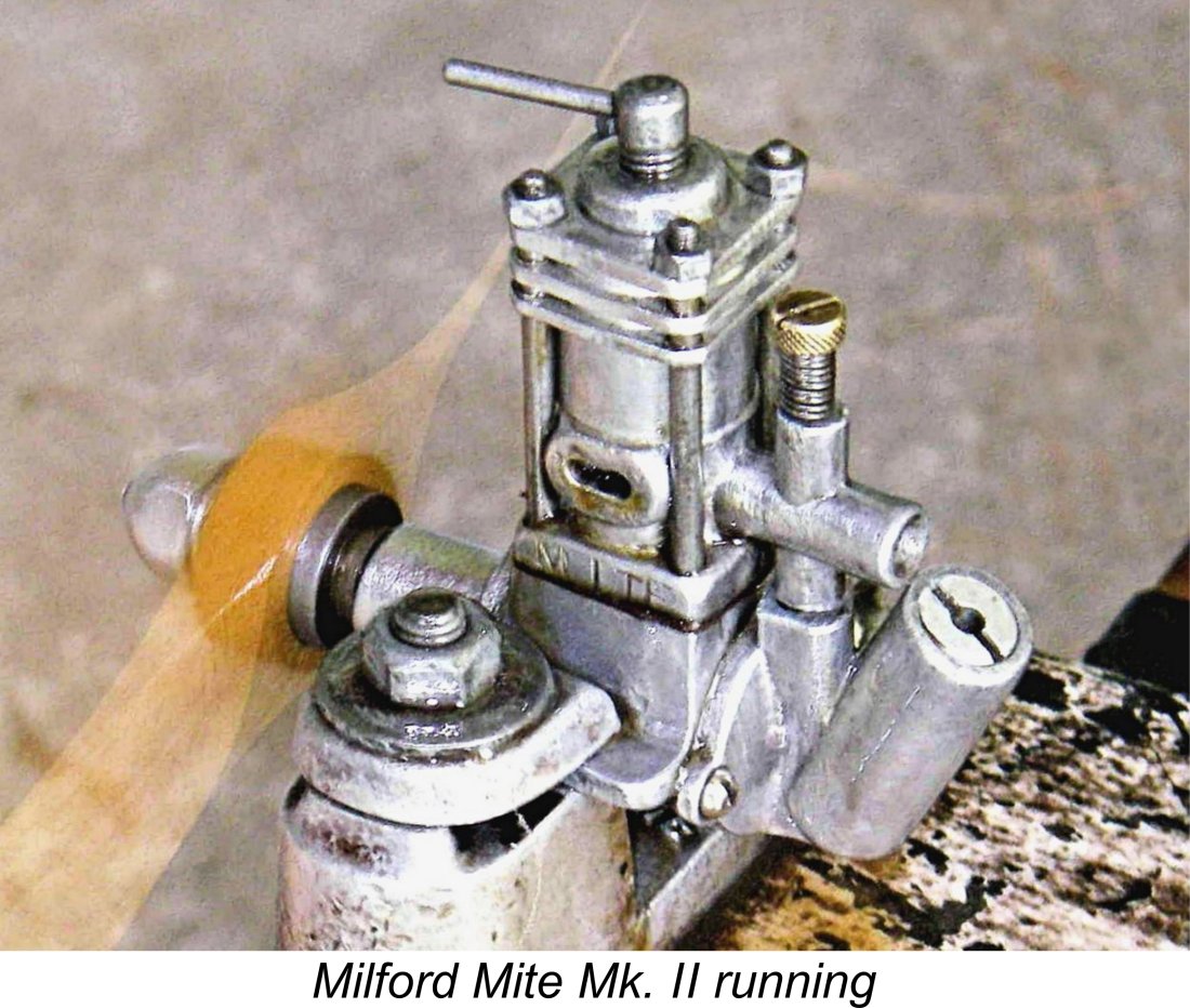 As noted earlier, the needle valve on the Mk. II proved to be far more sensitive than that of the Mk. III in terms of the optimum setting. Another issue was the large variation in fuel head as the level in the unusually deep tank went down. The engine had to be set a little rich when starting on a full tank in order to have it "come in" to an optimum mixture setting towards the end of the run.
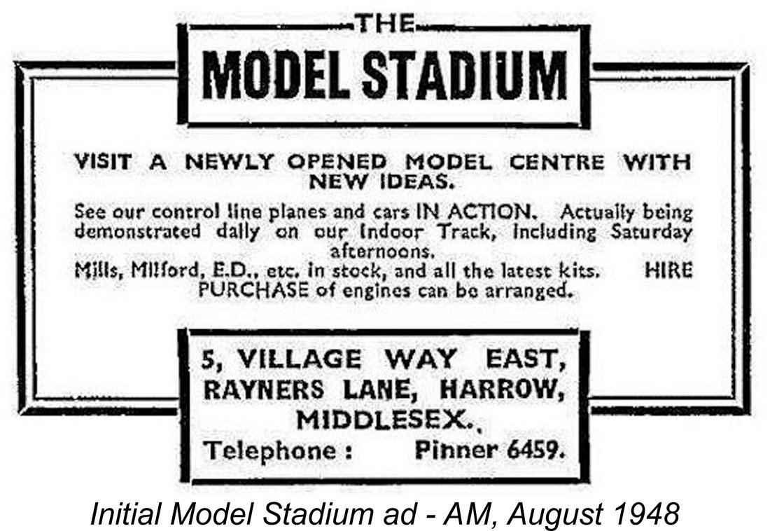
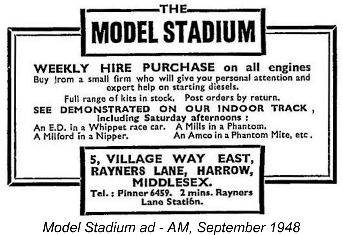 The Model Stadium advertisement for the following month of September 1948 offered further insights into the changed business focus of the reorganized company. Some of the demonstration models were specifically mentioned, including "A Milford in a Nipper" (presumably a Veron Nipper C/L trainer). A full range of kits was said to be in stock, along with an offer of "expert help" in learning to start a diesel engine.
 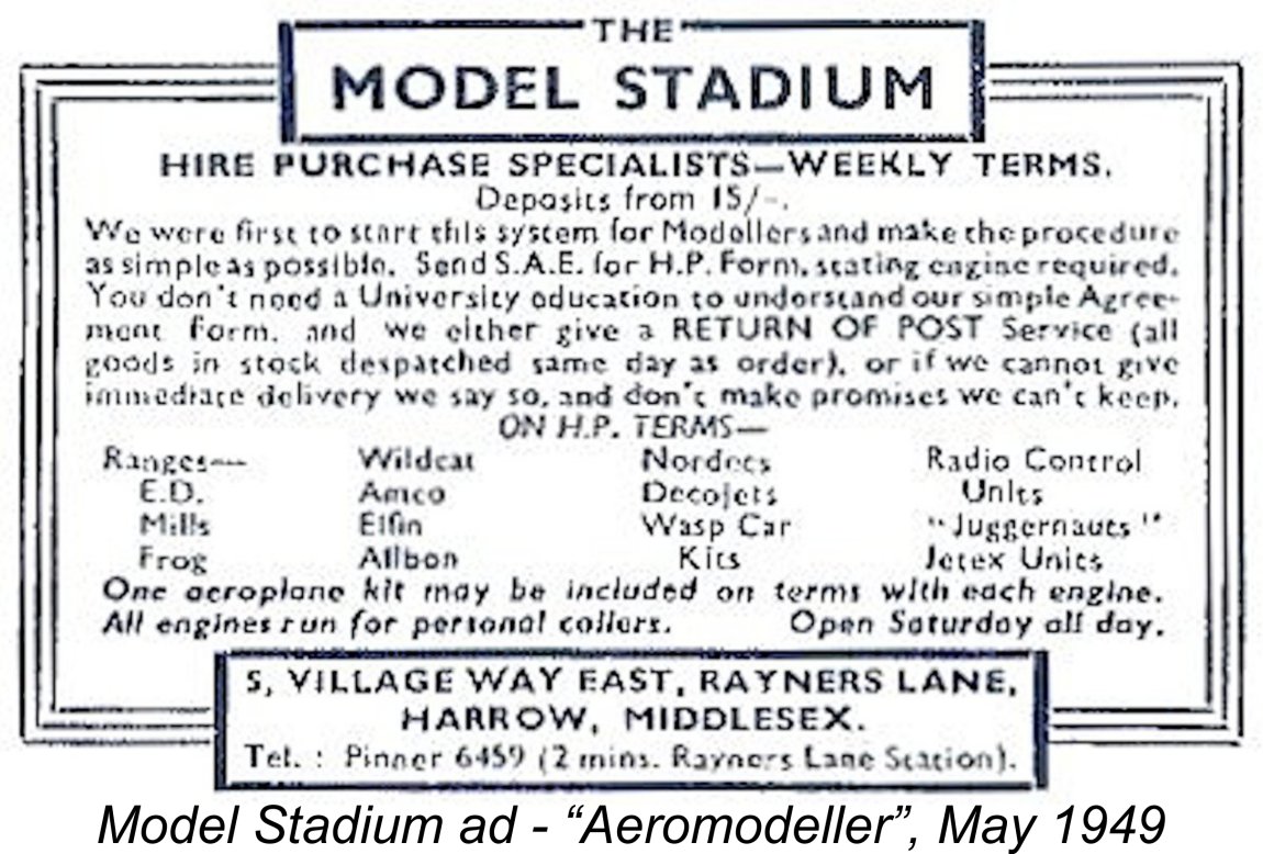 The renamed company offered a range of modelling goods, including both kits and engines of various makes. Interestingly enough, the new company continued the previously-mentioned hire purchase option first offered during the final months of the Milford Mite; in effect, an early example of buying on credit before such buying became the norm. Some degree of continuity in management is likely
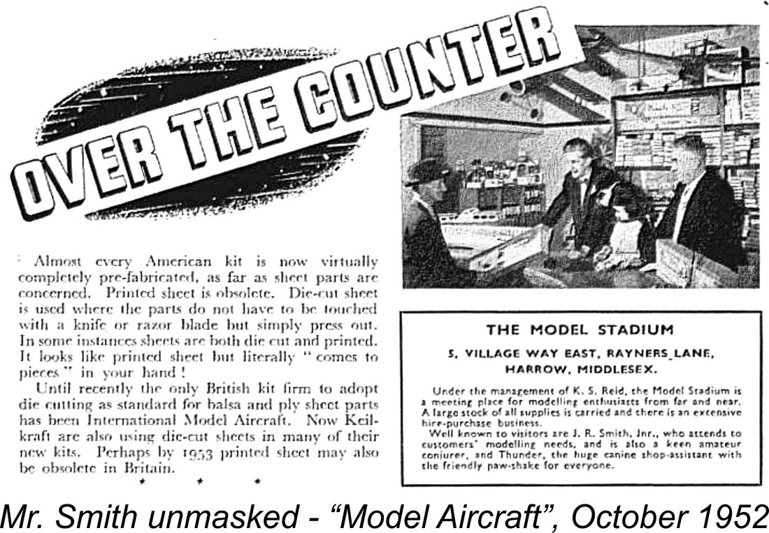
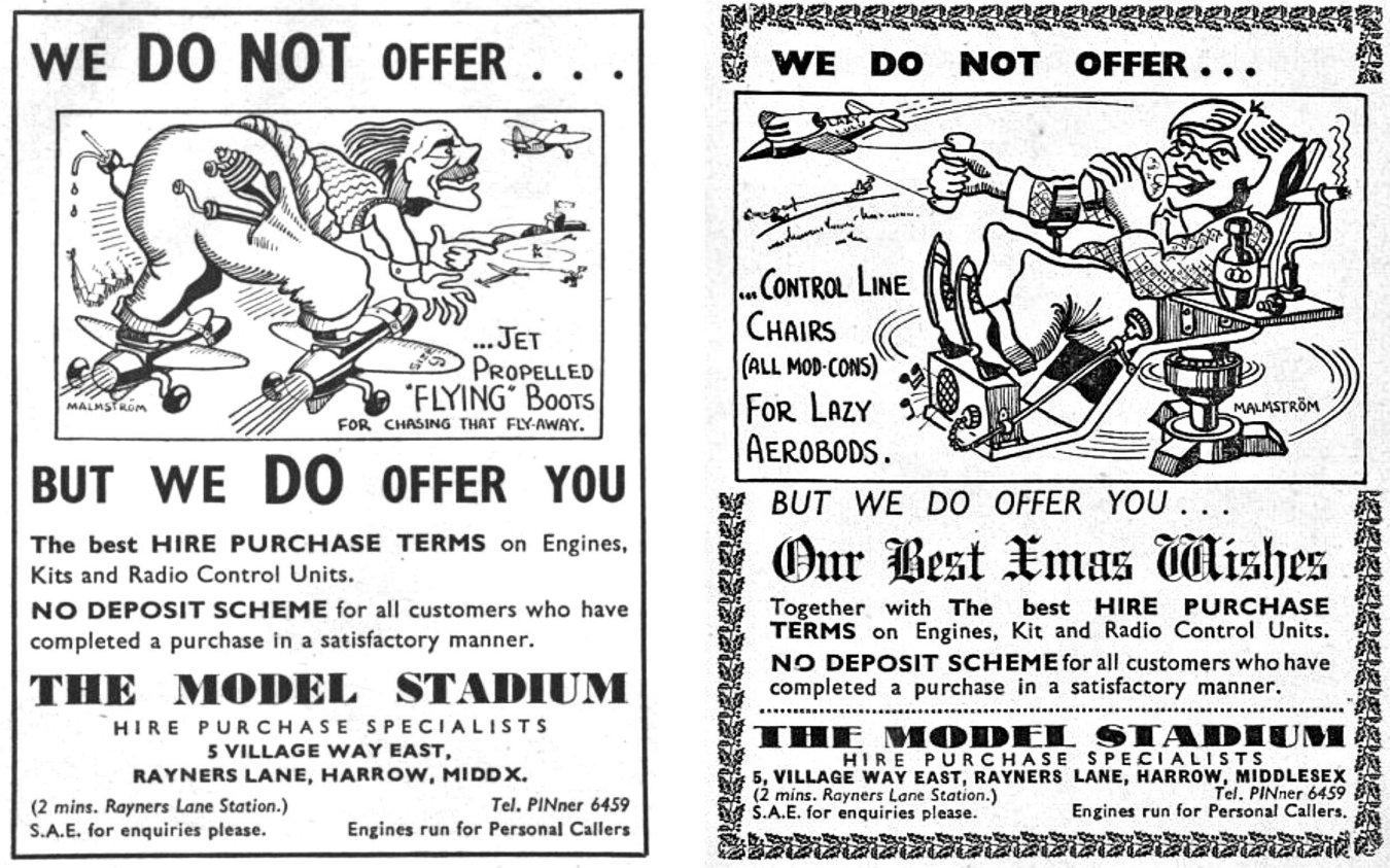 series of hilarious drawings depicting Ray’s unique visualisations of certain familiar aeromodelling terms! These cartoons alone made the searching out of the Model Stadium ads in each magazine issue well worth the trouble - some of Ray’s best work, albeit generally overlooked in retrospectives on his life and accomplishments. I strongly suspect that our friend Mr. Smith was continuing to display his flair for creative
 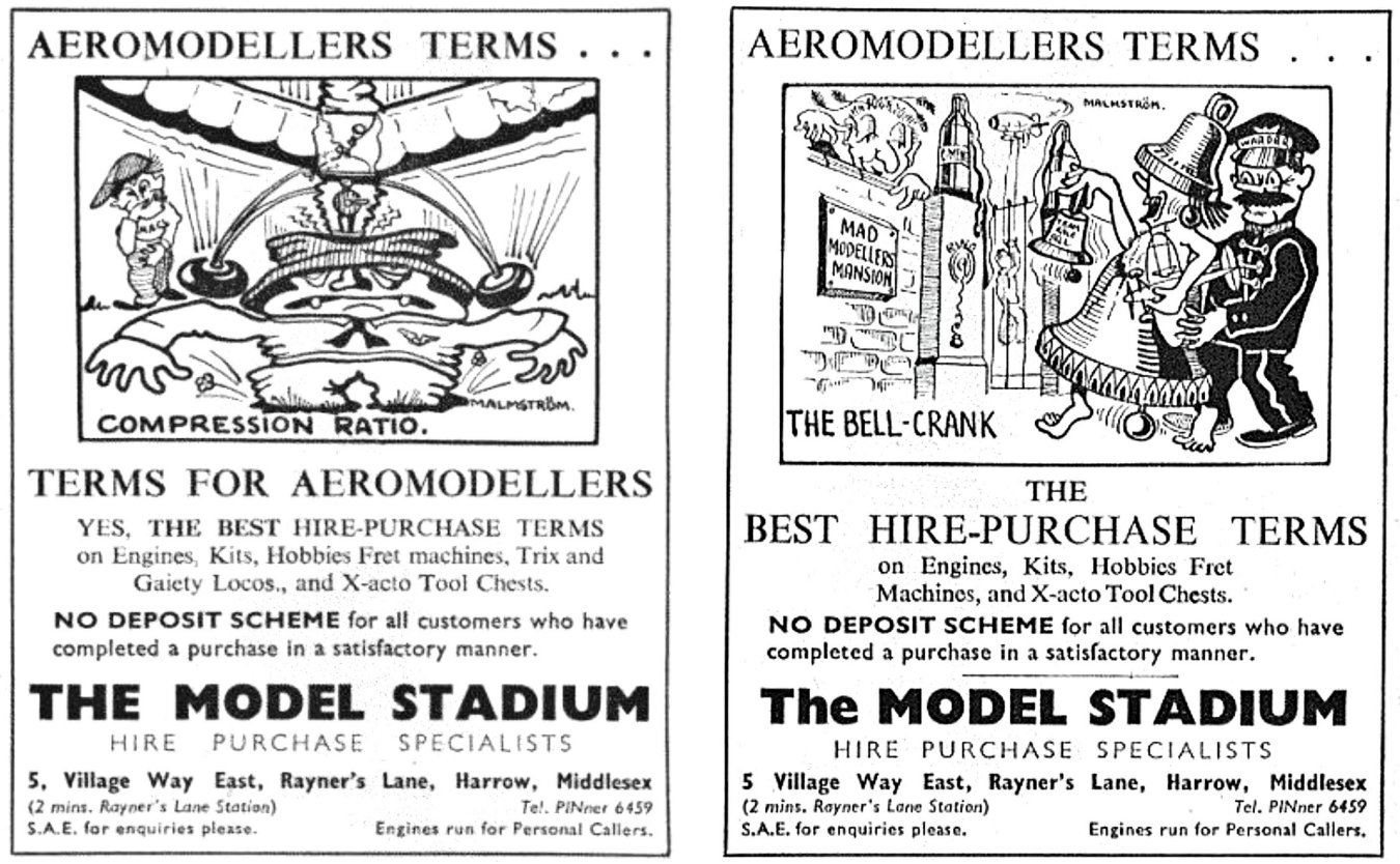 Quite apart from their value in the enhancement of the advertisements, these cartoons serve in themselves as a reminder of the immense contribution which Ray Malmström made to the enjoyment of their hobby by countless aeromodellers worldwide. Any hobby which receives support from artistic talents such as Ray's may consider itself fortunate indeed!
 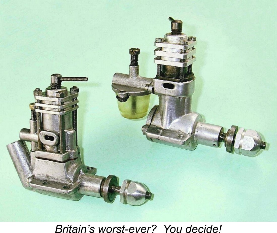 If your criterion is general "useability", then once again it's hard to think of a less flexible British diesel than either of the first two variants of the Mite with their tiny built-in tanks which severely restricted the available motor run, did not permit the use of a separate fuel tank and thus restricted the engines to free flight applications using upright mounting only. The third variant with its revised tank was considerably more flexible in terms of potential applications, but that was definitely a case of too little, too late.
| |