
|
|
The Model Dockyard Cub By Maris Dislers
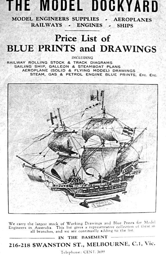
The Model Dockyard’s earliest engines may have been offered only as kits of castings and plans. These included the 25 cc “Grayson” 4-stroke, the 15 cc “Grayspec” 2 stroke, the heavy-duty horizontal water-cooled 25 cc “Vanguard Senior” gas engine, the 25 cc two-stroke "Vanguard Atom" and the 12 cc 2-stroke “Vanguard Junior”. For the most part, these units were likely destined for use in tethered speed boats or hydroplanes.
The marketing claim that the Whirlwind was “The most popular general-purpose engine in Australia” was true only because during WW2 it was essentially the only engine on the market! The Whirlwind went through several makers and different models, ending in the early 1950’s. The accompanying image illustrates the extent of some of the changes, which were sufficient to create a completely different engine bearing the same name.
Better suited to model aircraft applications, the Model Dockyard’s 7 cc “Vanguard Pup” model (essentially a clone of the Bill Atwood/Mel Anderson Baby Cyclone) was also marketed around the same time, but in much smaller numbers. Also, a few examples of the “Hurricane” (essentially a clone of the 10 cc Hornet racing engine from America) were offered after WW2. The Model Dockyard Cub Origin Mystery
Ham Harvey sold his Central Aircraft Co. not long before WW2 to partners Major George Mason and Captain James, then owner of the Model Dockyard. Perhaps the attraction was Central’s growing model aeroplane kit production, at a time when aeromodelling was the fastest-growing technical hobby in Australia. We do not know who designed or manufactured the Cub engine, or when they first appeared. Although this model is quite unlike the Whirlwind, it embodies design features firmly rooted in the pre-war era. Perhaps it was originally designed as a crossflow-ported engine and was mothballed when the actual maker went into war service work for the duration. Under this scenario, eventual postwar production began with the cross-flow engine shown in the Model Dockyard catalogue. Whether it’s a Central Aircraft Gnome or the short-lived original Model Dockyard Cub variant (or both), the extreme rarity of this variant suggests that production was very small. The marketed construction plan for the spark ignition Cub is titled “New Era 3 cc Motor” without brand or draughtsman’s name. The design features the T-scavenged cylinder porting (single front transfer port between two opposed exhaust ports) and flat-top piston that was first seen on the DYNO 1 diesel. This arrangement only became common knowledge outside of continental Europe after peace was declared. Perhaps a decision was quickly made at that point to drop the earlier 3 cc engine’s cross-flow porting to facilitate the eventual development of a diesel version while retaining most of the original components. In spark ignition form this became the recognised twin-exhaust Model Dockyard Cub, which probably appeared in 1947. The Cub Described
The result was a relatively compact and light 158 gm (5.6 oz) engine, complete with spark plug. The engine looks somewhat overshadowed Also noteworthy is the unusual spring and ball bearing ratchet for the fuel mixture needle. This works excellently in use. This ratchet design has also been noted on several examples of the Whirlwind within the same serial number range. The catalogue cites both bore and stroke as 5/8 in., which would yield a displacement of 3.14 cc. However, the stroke of the few available production examples of this engine matches the construction plan at 11/16 in., giving a nominal swept volume of 0.211 cubic inches (3.46 cc). Measured port durations are: intake 87 degrees, transfer 105 degrees and exhaust 112 degrees. Compression ratio is a little under 4.7:1. The Cub Diesel
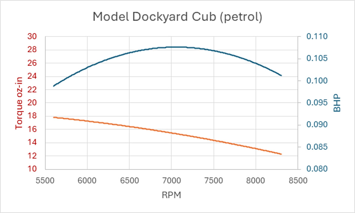
The crankshaft was made from high-grade steel with a 12.5% larger journal diameter than that of the sparkie. It incorporated oil feeder holes and extra crankweb counterbalancing, although The unusually shallow contra piston (height less than 1/5th bore diameter) had a threaded spigot both for facilitating withdrawal and seemingly to prevent skewing by registering inside the The plan for the Cub 3 cc diesel shows dimensions in inch fractions. Such dimensions were typical at the time but are very difficult to use in my opinion, since they require conversion to the decimal figures registered by precision measuring equipment such as micrometers - a potential source of error. Their appearance on the plan may have caused some difficulties for home constructors of the engine. Running the Spark Ignition Cub All test runs were made in clockwise rotation, knowing that this was the only way to guarantee that a crankpin with a right-hand installation thread will stay put during operation. The non-availability of suitable pusher props forced the use of regular tractor props for these tests. Providing that runs were kept short, the Cub tolerated such running well considering the lack of cooling propeller blast when using regular calibrated tractor propellers. We tested the engine in this way on both petrol and methanol-based fuels. I rate the Cub as a thoroughly delightful engine to start and operate. Some finesse in priming routine is required, but once the ideal measured small prime is found, it’s a piece of cake. The Cub was not so keen on making a clean two-cycle run, being better set close to the four-cycle to 2-cycle break, rather like a modern C/L aerobatics engine.The following prop/RPM data were obtained.
Individual data points were somewhat scattered due to this, but the trends show power on petrol peaking at 0.107 BHP around 7,000 RPM. Torque declined gradually - 0.1 BHP was recorded at the highest 18 oz-in developed torque at 5,600 RPM dropping to 0.1 BHP and 12 oz-in at 8,300 RPM. Sensible flyers would likely opt for a 10x6 or similar flight propeller, but with some leeway without drooping appreciably off the peak. Performance with methanol fuel was clearly better. The engine became more amenable to a clean two-cycle mixture setting and enhanced higher-speed running. The new power peak of 0.13 BHP at 8,000 RPM represented a solid gain, along with a 20% average torque lift. As glow-plugs came became available, Cub owners would likely have made the switch. Our tests with a 3/8 in. K.L.G. glow-plug resulted in almost identical results to those achieved with the gasoline fuel on spark. No surprise, as the very low compression ratio was clearly unsuitable for glow-plug operation. Of course, the absence of ignition troubles and ignition equipment weight would be of advantage. Running the Diesel Cub Any Cub is a rarity, but we know of only two production diesel Cubs in existence. We were fortunate to have one in excellent condition for testing via Ken Maier. The other one is hopefully safely preserved in the Richard Dalby collection.
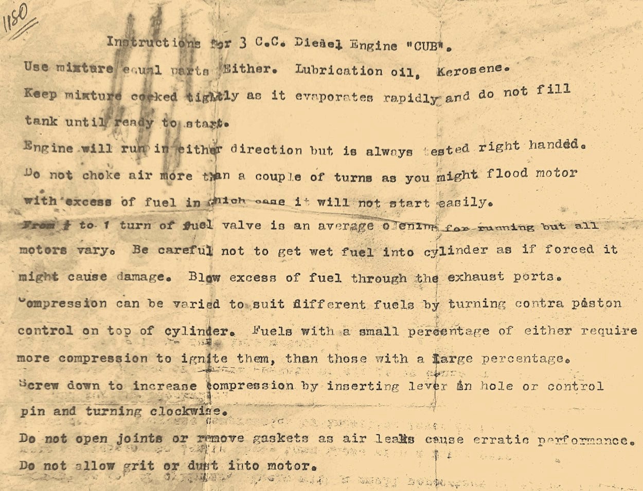
Fixing this condition required the removal of the contra piston to relieve the fit a little. Thank goodness for the threaded withdrawal spigot, even if that required the machining of a suitable tool. Surely easier than pushing it down the parallel cylinder bore without skewing. The typed original instructions specify equal parts “either” (sic), lubricating oil and kerosene. Incidentally, those instructions appear to be individually typed, supporting our assumption of truly miniscule production volume. All I can say after reading them is – good luck to any first-time diesel users!
Starts were again very good once the settings were found. These could then be left unaltered for subsequent starting. A light prime onto the piston crown worked well. Mixture adjustment lay within a click or two either side of the best spot. Even with the contra-piston fit having been eased a little, increasing the compression setting was still a struggle, partly due to the large and coarse thread size. The long compression screw lever was really needed. Adjusting compression was seemingly envisaged only when the fuel formula was changed. So, like the E.D. Mk. 2 “penny slot” engine, best done after stopping the engine. Not as specific as some, and operation slightly below the peak setting gave a comfy burbling run only a few hundred RPM less than peak. Backed-off running was a joy. Operation in this mode seemed better suited to the Hearns’ HM-3 or Model Dockyard/Central Stork model options, unless the aim was to poke holes in the cloud base. Restarting while still warm was almost instant and there was none of the excessive vibration or coarseness associated with such larger diesel engines of yore. We noted a certain lack of enthusiasm for the lighter 9x6 propeller. The engine was fine with 10x6 and best gruntled with 11x6. This behaviour was no doubt influenced by the mild port durations and the maker’s expectations when choosing a small effective choke area. We recorded 6,500 RPM with a 10x6 propeller for 0.1 BHP and 17.4 oz-in torque. 5,600 RPM with 11x6 for the same power but slightly higher torque. At those speeds the diesel was equivalent to the spark ignition Cub running on petrol. Serial numbers and production volume Model Dockyard engines were available as castings/plans sets. The number of those sold is not known. The quality of known DIY examples is typically poor, since they were often made by those unfamiliar with the finer points of model engine fits and finishes. Moreover, errors were easily introduced when converting those inch-fraction plan dimensions. Ready-to-run engines were stamped with serial numbers at the time of sale, regardless of type. Cubs were stamped on the back plate flange. The lowest number in my list of 31 examples of Model Dockyard engines is number 116, while the highest is 1364, representing the entire documented run of Model Dockyard engines. The implied average is around 100 units per year, most of which were Whirlwinds. My list includes the following numbers:
These give an insight to individual engine model sales during the period and likely quantity sold. Build quality of all Model Dockyard production engines was of a very high standard, while the retail price was consistent with output by artisans having no mass-production machinery. A Unique Cub ball race Diesel
Measurements imply that the crankcase was cast using the original pattern, rather than patterned from a casting, following ad-hoc addition of material to arrive at a crankcase suitable for housing ¼ inch ID ball races. The crankcase has a neat threaded dust cover up front. The piston has the same two oil grooves as our production diesel. The cylinder liner closes off the finished original side-port induction position. Perhaps the engine was initially run in side-port mode. The rotary intake timing of 210 degrees induction period seems more than adequate. The aperture for the accommodation of the intake tube is threaded 3/16 x 40 ME, implying a skinny intake tube with a very modest venturi choke area. This engine may have been produced by the maker as a one-off experimental unit to determine its potential for doing battle with the E.D. Mk. III and lesser diesels in the tether car class for smaller engines circa 1948. Summary The present-day rarity of Cubs (even accounting for likely low production volume) might stem from its screw-in crankpin feature. The maker evidently had great faith in that, as the instructions for the diesel Cub state “Engine will run in either direction but is always tested right-handed”. But should the crankpin ever come loose when running, the resulting damage to its fine 40 TPI thread would likely prevent effective retightening. Or tightening at all, if the engine kept clattering on for some time. You might scoff at the performance level from Cubs. However, it must be recalled that the more powerful American alternatives were not available commercially in Australia at the time, unless you knew someone in the USA who could send you one as a “gift”. In the company of first-generation Mills, E.D. and FROG engines, the Cub doesn’t look so bad. Mal Sharpe considered his Cub diesel to be quite powerful for its time. The engine’s ease of operation would have been valued by first time engine owners. Of course, by 1950 and beyond the situation had changed quite dramatically, with second generation British diesels and FROG 500 glow-plug engines coming on tap. By the early 1950s, the Model Dockyard “house” engines and perhaps their castings/plan kits were gone, as the traditional school of model engine design epitomised by Edgar T. Westbury had retreated into the realm of dedicated model engineers. ___________________________ Article © Maris Dislers, Glandore, South Australia First published September 2026 |
||
 The
The 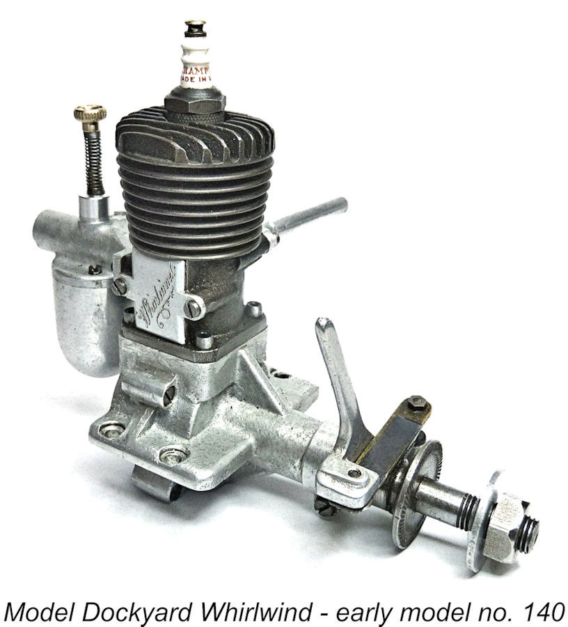 It’s possible that the growing interest in powered model aircraft in Australia persuaded the owners to commission a smaller 2-stroke type, to be made by others for sale in ready-to-run form. Information is now almost non-existent, but the late David Owen reported on his extensive research relating to the resulting 8.5 cc Model Dockyard “Whirlwind” sparkie in Merv Buckmaster’s “Aero Modelling Digest 1997”. The designer is unknown, but Cliff McGuinness is known to have made at least two prototype engines in 1936-37.
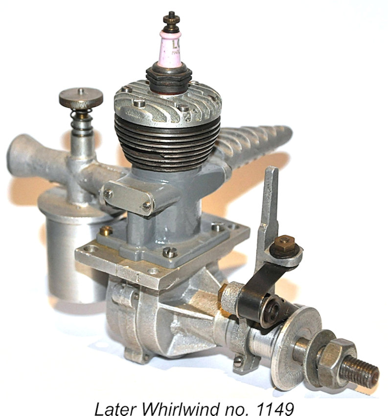 The production version of the Whirlwind (circa 1938) reverted to side-port induction, perhaps because an updraught carburettor dripping gasoline from a gravity feed tank into the hold of a model boat might end in tears. The 8.62 cc (0.526 cuin.) engine featured bore and stroke dimensions of 0.875 in. (22.225 mm) each. Its design had a whiff of the
 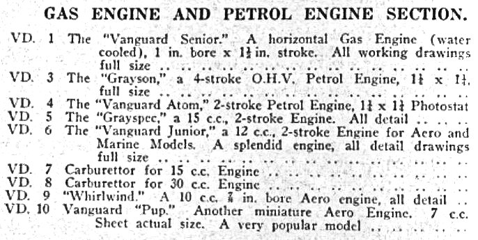 Even after the Model Dockyard began to offer complete ready-to-run examples of their engine designs, the entire range continued to be offered as sets of plans and castings. The acccompanying model engine listing from the Model Dockyard catalogue shows the range of available drawings and blueprints as it existed c. 1946-47.
 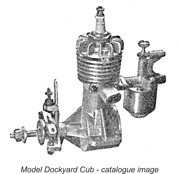 Smallest of the Model Dockyard engines, the story of the 3 cc Cub begins with a mystery. The catalogue image (left) shows a crossflow-ported engine, while all known Cubs have two opposed exhausts. Such apparent anomalies are not unusual when artwork is prepared before the final design is completed. All production Cubs have two opposed exhausts.
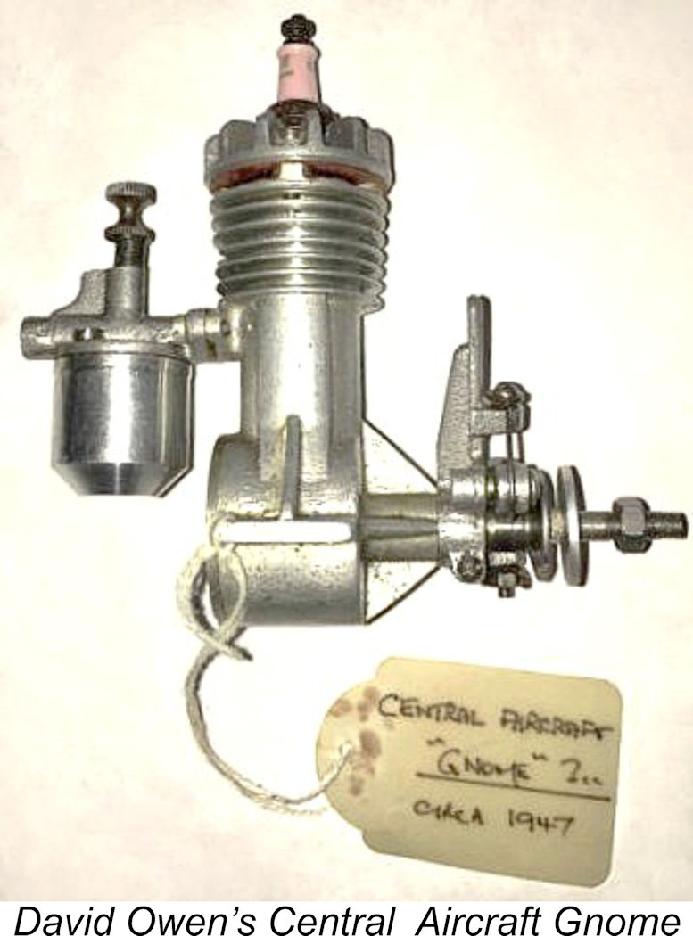 That having been said, the cross-flow variant’s existence did go beyond a mere pre-production prototype. One example was in David Owen’s collection, although slightly altered. This engine was labelled (presumably on good authority) as a “Central Aircraft Gnome”. Other sources also mention the Gnome engine and one was shown on the plan for the 44 in. wingspan HM-3 kitted by Hearn’s Hobbies circa 1947. This is as close as we got to finding any documentary evidence.
  Under the new ownership, Central Aircraft Co. continued in business at 5 Princes Walk, Princes Bridge, Melbourne at least into the 1950’s.
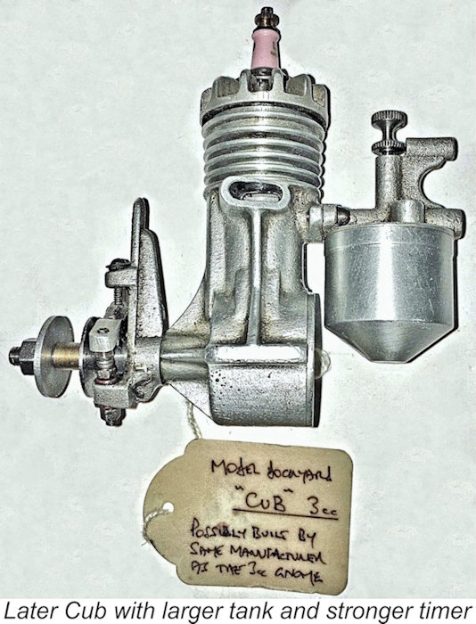
  The Cub's sand-cast monobloc aluminium crankcase featured beam mounting lugs supported by webs, a webbed main bearing housing, two opposed exhaust stubs and machined cylinder cooling fins. Extensive use was made of castings for other components as well. The engine featured a pressed or shrunk-in cylinder liner of drawn steel tubing along with a cast iron piston. Later Cubs had slightly thicker lugs, a stronger timer arm with perpendicular web and a larger fuel tank bowl, perhaps with control line flying or tether cars in mind.
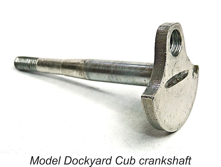
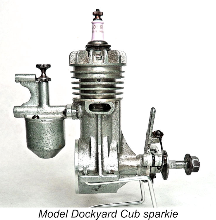 The crankshaft was produced from a car engine intake or exhaust valve – an interesting approach to the reduction of manufacturing cost. The visible indentation in the centre of the crankweb is the giveaway here. The use of a separate screw-in crankpin (right-hand thread) was a necessity for assembly, as the piston and connecting rod assembly must be inserted vertically downwards as a unit from the open cylinder installation bore.
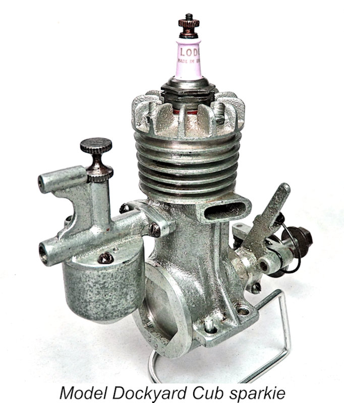 by the size of its 3/8-24 spark plug, which looks out of place for this nominally 3 cc engine. However, the smaller ¼ inch size might not have been available in Australia when the engine was designed and made. Whirlwinds supplied during wartime had by necessity been fitted with ungainly 10 mm spark plugs normally used in motor vehicles
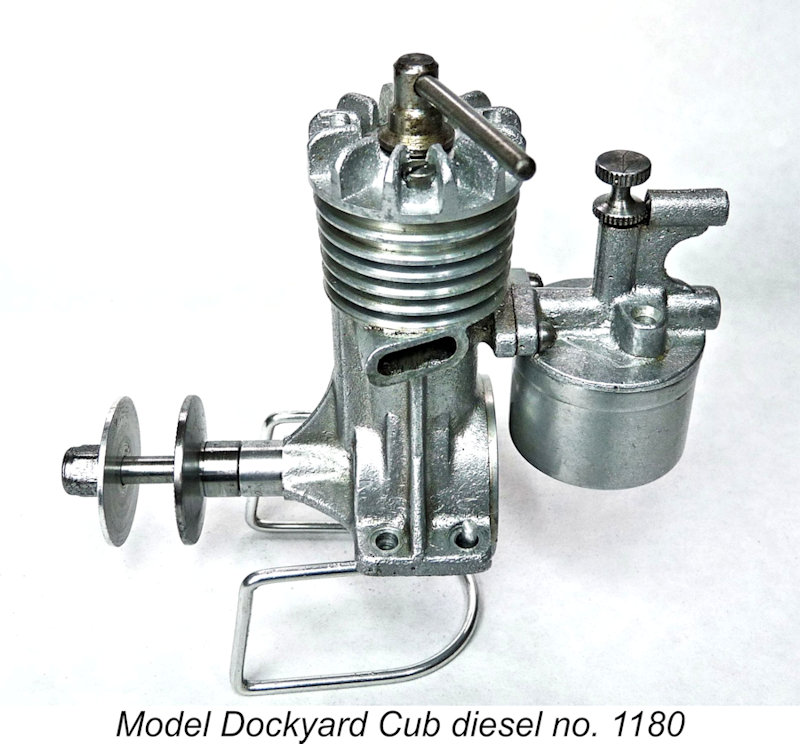 This variant was most likely first marketed in late 1948, going by a brief review by “Footslogger” in the December 1948 issue of “Hobbies Illustrated”. The writer praised its light weight (165g or 5.8 oz) and strong shaft material but didn't report having undertaken any actual testing. He enthused about being able to revert to spark ignition simply by removing the contra piston. A curious observation considering that such a conversion would also necessitate a prop driver with cam, a complete timer assembly and heavy ignition support equipment.
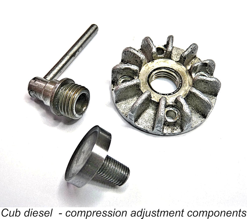 space considerations limited the crankweb’s thickness to only 1/8 in. (3.2 mm). This may have been more or less adequate for spark ignition operation, but it appears to be a structural weakness in the diesel version of the engine, inspiring little confidence.
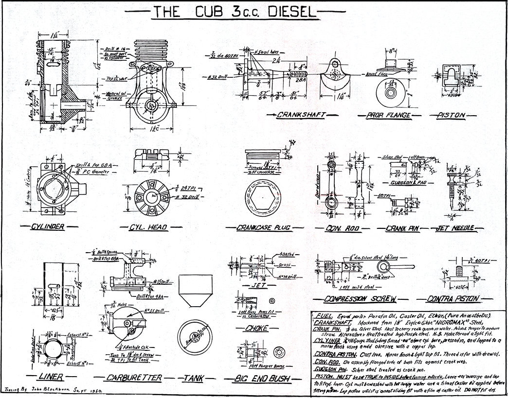 compression screw. The comp screw threaded into the 3/8-24 TPI spark plug cylinder head thread. The propeller driver had a larger-diameter face for better propeller grip. The engine’s machined dural connecting rod was provided with a bronze big end bush. The effective choke area of the intake venturi was reduced to 4.33 mm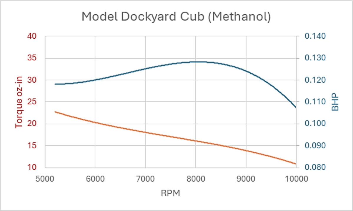
 During preparation for these tests, the contra piston was found to be too tightly fitted, risking a stripped cylinder head thread. Tell-tale carbon deposits on the piston crown and combustion chamber surface, along with the compression screw being wound down to its flange stop, suggested that the original owner had worked it in a “fixed” and over-compressed state. Not much fun, and perhaps explaining why the engine was so little used. However, the fact that the crankshaft had survived this mistreatment did provide some assurance of sufficient crankshaft web strength for a few test runs to lightly gauge the engine’s merits.
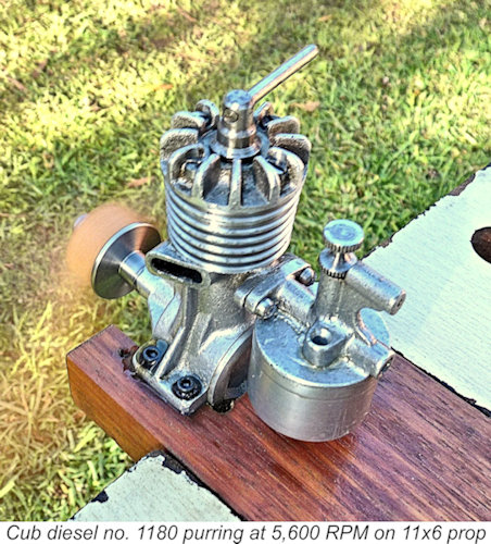 We tested the diesel with equal parts ether, kerosene and Aeroshell 100 (SAE 50) mineral oil, plus 0.8% ignition improver. Straight fuel would likely need a higher (and riskier) compression ratio. We also tried a regular modern mix with 25% castor oil and 1.5 % improver. That was perhaps worth a few hundred RPM after careful warming up to stable temperature.
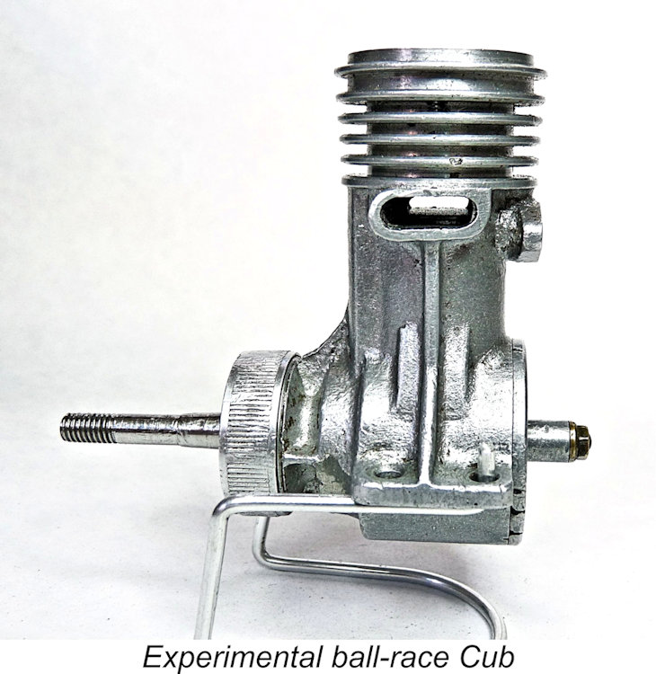 As a final treat, we have a fascinating incomplete Cub with its crankshaft mounted in twin ball races and featuring disc rotary valve induction. This example is missing the intake carburettor and cylinder head and with bare crankshaft. The engine was seemingly sidelined when half the crankpin flange had broken off, preventing effective driving of the rotary induction disc. The engine feels stiff – as if something is bent. I suspect the crankweb rather than the
 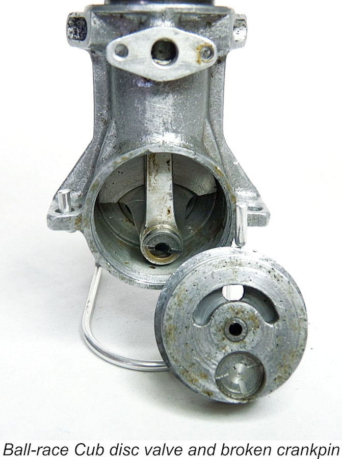 chunky dural connecting rod. There’s no provision for the mounting of a spark ignition timer, implying that the engine was originally a diesel.
 | |