
|
|
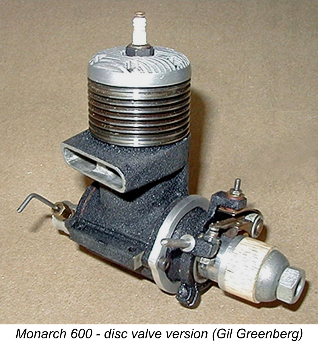
The Monarch 600 – One of Canada’s “Lost” Racing Engines This engine is so rare today that one is forced to the conclusion that it was a very limited-production design indeed, perhaps individually constructed to special order. It seems extremely unlikely that total production reached three figures or anywhere near it. Having been fortunate enough to acquire my own example, I found myself in a very good position to undertake a review of this very rare unit. My late good friend and valued colleague, former “Engine Collector’s Journal” (ECJ) publisher Tim Dannels, then of Buena Vista, Colorado, USA, was deeply involved with engine collecting and model engine history for many decades, hence knowing as much as the next three individuals combined about North American model engines. Despite this, Tim confirmed that he had never even seen so much as an image of a Monarch until the late 1990’s. Even 20 years later at the time of writing of this article (late 2017), he was aware of only three surviving examples – that which I now own plus those formerly owned by the late Ward Hallenberg and the late Gil Greenberg, the present whereabouts of which are unknown (mine is not one of them). I should take this opportunity to record my indebtedness to Tim for his unstinting assistance during the preparation of this article, including the provision of a number of the images which appear here. He is greatly missed.
This example had reportedly been mounted and used, but was said to be in fine mechanical condition. Even more interestingly from a historical research standpoint, it was still accompanied by its instruction manual. For a historian like me, that's treasure trove indeed! My attention was very kindly drawn to this eBay offering by my valued Aussie mate Maris Dislers. Although it wasn’t the ideal time to be splurging on another model engine with Christmas just around the corner, I immediately recognized this as a once-in-a-lifetime opportunity to study this very rare Canadian product and perhaps do something to bring it out into the light. So I dug deep and ended up acquiring the engine. It turned out to be just as described, having evidently seen only a little use. Maris, I owe ya, mate! Upon receipt of the Monarch, I immediately set about investigating the engine’s structural features with the goal in mind of giving it a few test runs if I judged it to be up to the task from a mechanical standpoint. But before I report on those activities, I think that considerations of context require me to present a long-overdue summary of Canadian model engine manufacturing during the early post-WW2 period. The Canadian Model Engine Manufacturing Scene in the 1940’s Canada is definitely not the first country that comes to mind when the subject of commercial model engine manufacturing comes up. In large part this is doubtless due to the combination of two factors – one, Canada's huge geographic area which created a very wide spread among a relatively small population and hence a highly fragmented domestic marketplace; and two, the presence of a ready source of competitively-priced engines which were mass-produced to a high standard immediately south of the border in the USA. The first of these two factors tended to restrict model engine manufacturing in Canada to small-scale ventures located in major population centres which produced limited numbers of engines primarily intended for the local Canadian market in the immediate area of production. The competition from the USA made it very difficult for Canadian manufacturers to compete price-wise in the broader marketplace. Those few who tried certainly deserve our respect!
The Ajax engines were predominantly marketed through the St. John Model Shop on Portage Avenue in Winnipeg, although a couple were sold in Saskatoon, Saskatchewan and a small number in Minneapolis, Minnesota. The associated brochures specifically cited this engine as “the first motor to be manufactured in Canada”, seemingly confirming its priority. According to research carried out by Paul Knapp and Arthur Polson and published by Tim Dannels in ECJ no. 221 (April 2014), around 20 examples of the Ajax were constructed and sold between March 1938 and sometime in 1939. No surviving examples of the production model are known today, although one of the 1937 prototypes does survive along with a few brochures and advertisements. The venture was doubtless killed off by the previously-mentioned competition from the neighbouring USA as well as by the onset of WW2, in which Canada was engaged from September 1939 onwards.
The next model engines to be produced commercially in Canada were the Strato series of 0.604 cuin. models which were constructed between 1940 and 1946 by an individual named Randall Bainbridge (1913 - 2006) of Montreal, Quebec using the registered trade-name of Strato Model Engines. According to the genealogical information very kindly tracked down by Tim Dannels' son-in-law Sheldon Jones, Bainbridge had been born in northern England on January 1st, 1913 at Tynemouth, Northumberland. Bainbridge's father was a bricklayer who emigrated with his family to Quebec, Canada in 1925 when his son was 12 years old. Randall followed in his father's footsteps by also becoming a bricklayer, living the rest of his long life in Montreal and finally passing away there on March 7th, 2006 at the grand old age of 93. The sideport units constructed by Bainbridge generally followed the standard design style for general-purpose engines which had evolved in North America during the nineteen-thirties. They were individually constructed to very high standards - Bainbridge was clearly a very talented model engineer. When considering the Strato venture, it must be remembered that unlike the neighbouring USA, Canada was heavily embroiled in WW2 at the time in question, with a consequent re-focusing of national attention away from hobbies such as aeromodelling as well as a diversion of both materials and precision engineering capacity into war production. Indeed, it’s a bit of a matter for wonder that Bainbridge managed to produce any model engines at all under the circumstances! It seems certain that model engine manufacture was a sideline hobby activity for Randall Bainbridge. Since he was 27 years old when he produced his first engine in 1940, Bainbridge was definitely of military age. However, he was not called up when Canada began to implement conscription in 1944, a move which was strongly opposed in Quebec. According to his nephew Robert Lejeune he contracted tuberculosis in 1942, spending a year in the Montreal T.B. sanitorium and eventually having a lung removed. This would have rendered him unfit for military service. Following his recovery and release, he returned to his bricklaying occupation.
Somewhat unusually for its date of manufacture, the Strato was a short-stroke design having bore and stroke dimensions of 0.9375 in. (23.81 mm) and 0.875 in. (22.22 mm) respectively. My thanks to my good friend and colleague Peter Rathke for providing the attached image. This model’s main drawback was its weight – all of 15 ounces (425 gm) exclusive of the ignition support components. That’s a lot for a simple plain bearing sideport unit of this displacement! After only some 10 examples had been built, a somewhat lighter Mk. II model was developed having revised crankcase and cylinder castings produced in light alloy from permanent molds. There were also performance-related changes to the engine’s porting dimensions and timing. About 8 examples of this second variant were manufactured before production seemingly ground to a temporary halt, likely due to the ongoing exigencies of wartime. It's actually somewhat unclear who Bainbridge's customers may have been at the time in question when other priorities predominated.
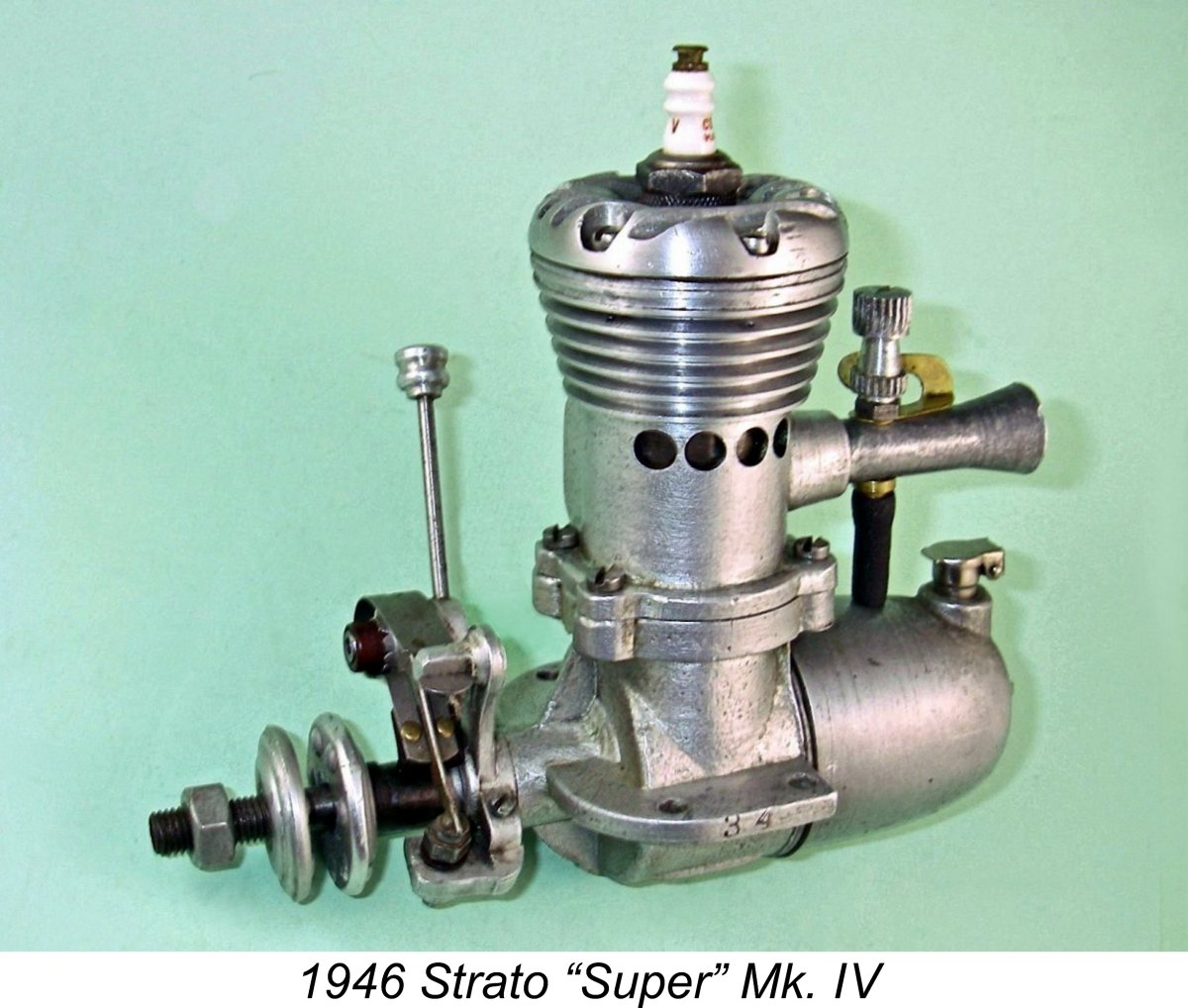
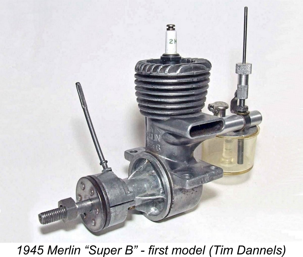
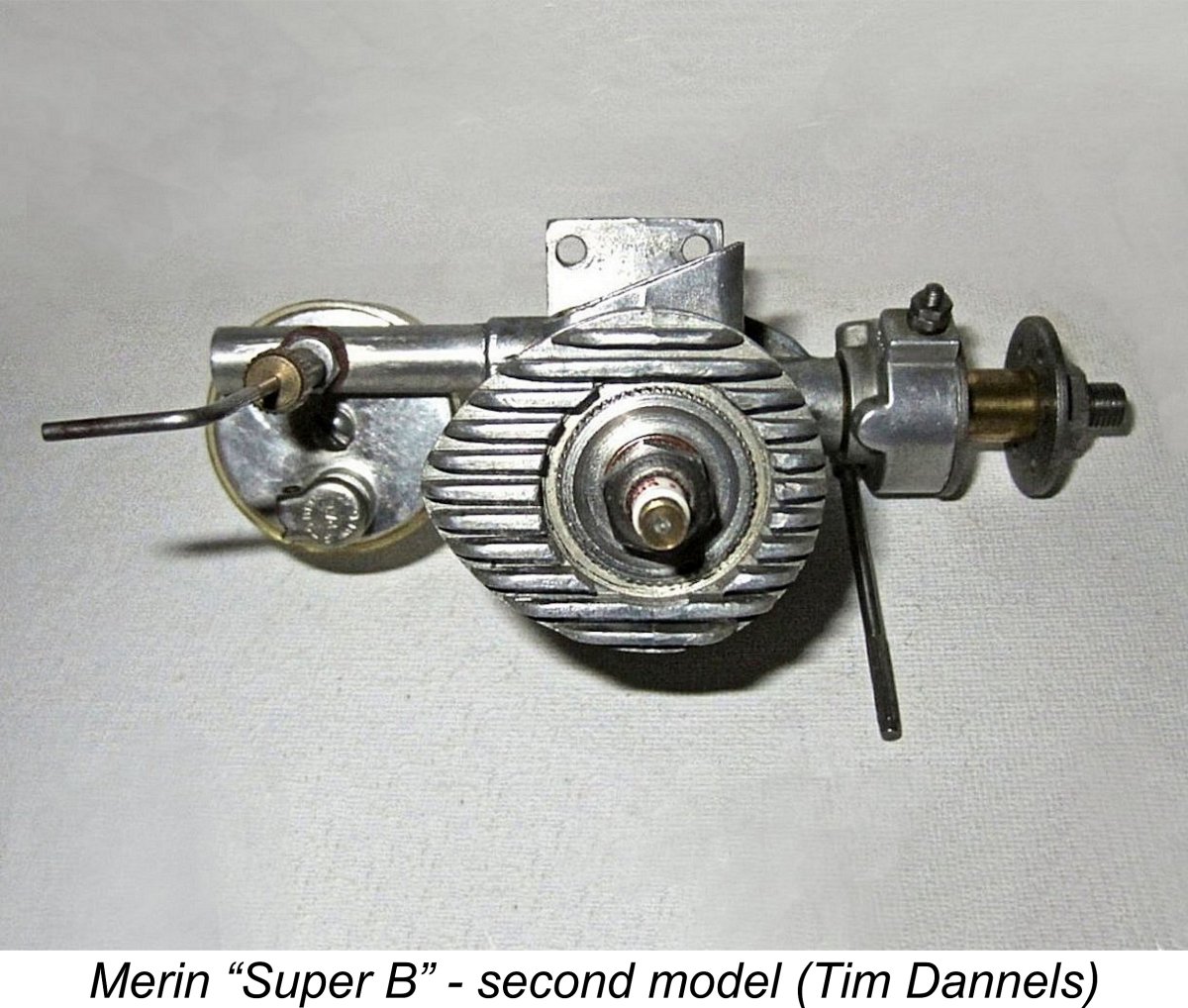
The final Strato design to make a commercial appearance was the Strato “Super” Mk. IV which made its debut in 1946. It was another .604 cuin. spark ignition sideport unit which featured a completely revised set of castings and a different method of assembly using bolts instead of screw-in components. Most of these engines such as illustrated engine no. 34 featured metal tanks, but a few later examples sported plastic items. Bainbridge also produced two crankshaft front rotary valve (FRV) units and a single fixed compression diesel as experiments, but these never saw production. Sadly, Bainbridge found that with his very limited production capacity based upon individual construction to very high standards he could not However, his efforts had not gone unnoticed! It’s very likely that these efforts inspired a number of other Canadian manufacturers to enter the model engine field at the conclusion of WW2. Among these was a firm called Merlin Miniatures of Toronto, Ontario, which was owned by a gentleman named Sam Crystal. This company’s flagship product was the 0.232 cuin. (3.80 cc) Merlin “Super B” spark ignition unit. This well-made and lightweight engine appeared in three successive variants between 1945 and 1947. It was manufactured in considerable numbers. The first model of the Merlin “Super B” as illustrated at the right had an exhaust stack with an outer end which was parallel to the engine’s main axis. The serial numbers were stamped on the top of the right-hand mounting lug, beginning with the letter “A”. The second variant was basically similar, but the outer end of the exhaust stack was now sharply angled towards the rear. Both variants had “Made in Canada” Interestingly enough, the rearward angling of the exhaust stacks on the later models was created with the use of a bandsaw or some equivalent tool. This implies that the same casting was actually used throughout. The final variant was supposedly manufactured in the USA, although the possibility exists that they were merely assembled in whole or in part from components shipped down from Canada. They were marketed by a Brooklyn-based firm calling itself Merlin Miniatures, Inc. Its only given address was Box 33, Station V, Brooklyn 15, New York - no actual location was provided. The supposedly US-made Merlin was essentially identical to the second version, including the rearward-angle exhaust stack created by sawing, but lacked the “Made in Canada” stamping, while the serial number was now stamped onto the intake tube. In addition, the edge of the cylinder retaining ring was now serrated, presumably to allow the use of a special tool for tightening. A very positive test of the American-made Merlin “Super B” by Louis Garami appeared in 1947 in the pages of “Air Trails” magazine. Production of the Merlin "Super B" seems to have ended in late 1947 or early 1948, presumably as a result of the arrival of the commercial miniature glow-plug in late 1947. There's no evidence that a glow-plug version of the engine was ever developed.
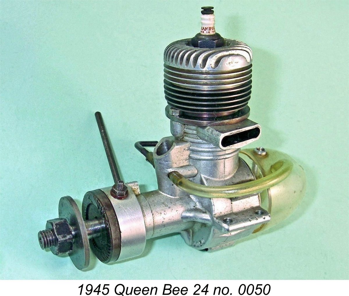
Apart from their serial numbers, neither the Queen Bee 24 nor 29 bear any marks of model identification. They look very similar, to the point that they have often been confused. The 29 has slightly larger cylinder and crankcase external diameters, but that’s not much help unless you have both models side by side.
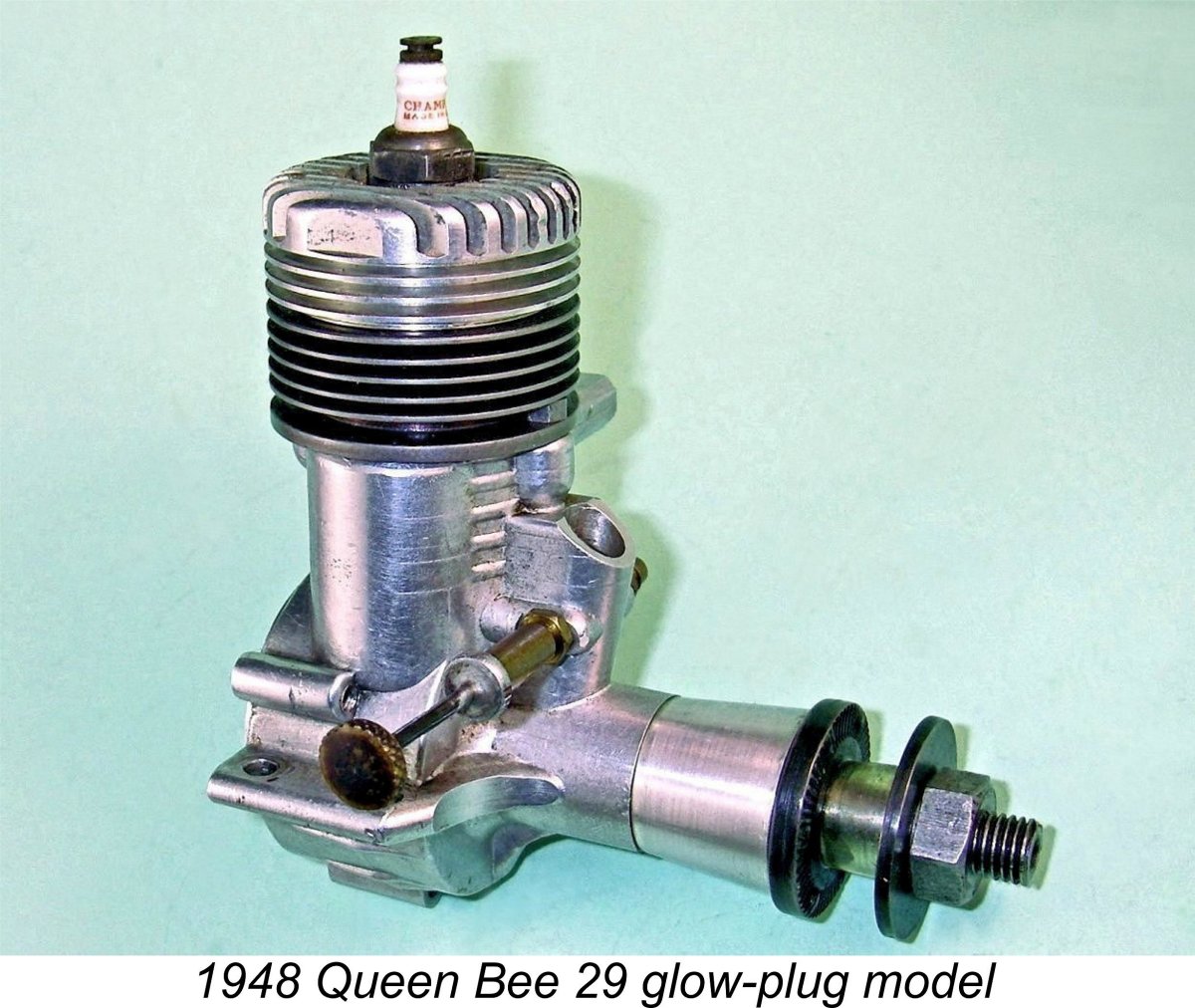
Both models carry serial numbers stamped onto the front of the crankcases. My own 24 bears the number 0050, while my two examples of the 29 carry numbers 0118 and 0131. If the reported total production figure of 140 examples of the 24 is correct, this implies that the sequence was re-started when the 29 came out. More serial numbers would be required to clarify this point. The final commercial offering from the Salonen brothers was a glow-plug version of the Queen Bee 29 which appeared in early 1948 shortly after Ray Arden’s late 1947 introduction of the commercial miniature A few experimental prototypes were also constructed, including around half a dozen diesel variants as well as one example each of a pair of .60 cuin. FRV units featuring glow-plug and spark ignition respectively. However, none of these prototypes ever reached production status. Production of the Queen Bee engines was quite small – probably no more than 400 units of all types were constructed in total. In the interests of conservation, two points should be mentioned here. Firstly, these engines should not be dismantled without really good cause. The cylinder is retained by two nuts on studs located fore and aft which act directly upon the cylinder installation flange immediately above the exhaust port. The nuts are thus necessarily positioned inside the lowest cooling groove. Even using the appropriate tool, their removal and re-installation is a royal pain which can easily cause damage to the cylinder. In addition, it is really difficult to re-establish both the correct cylinder head alignment and a good head seal when re-fitting the head. Best left alone …….. The other point to be aware of is that if you’re ever lucky enough to find a spark ignition example which retains its screw-in plastic tank, those tanks become incredibly brittle with age, shattering with almost no provocation. Handle those tanks with the very greatest care. and do not attempt to run the engine with the tank fitted!! The Queen Bee saga reportedly ended rather precipitately! Finding that he couldn’t compete price-wise with the new offerings from K&B, OK, Ohlsson and others, Al Salonen apparently expressed his frustration by throwing the Queen Bee dies and tooling into the waters of Vancouver’s Burrard Inlet! There they repose to this day ……………..
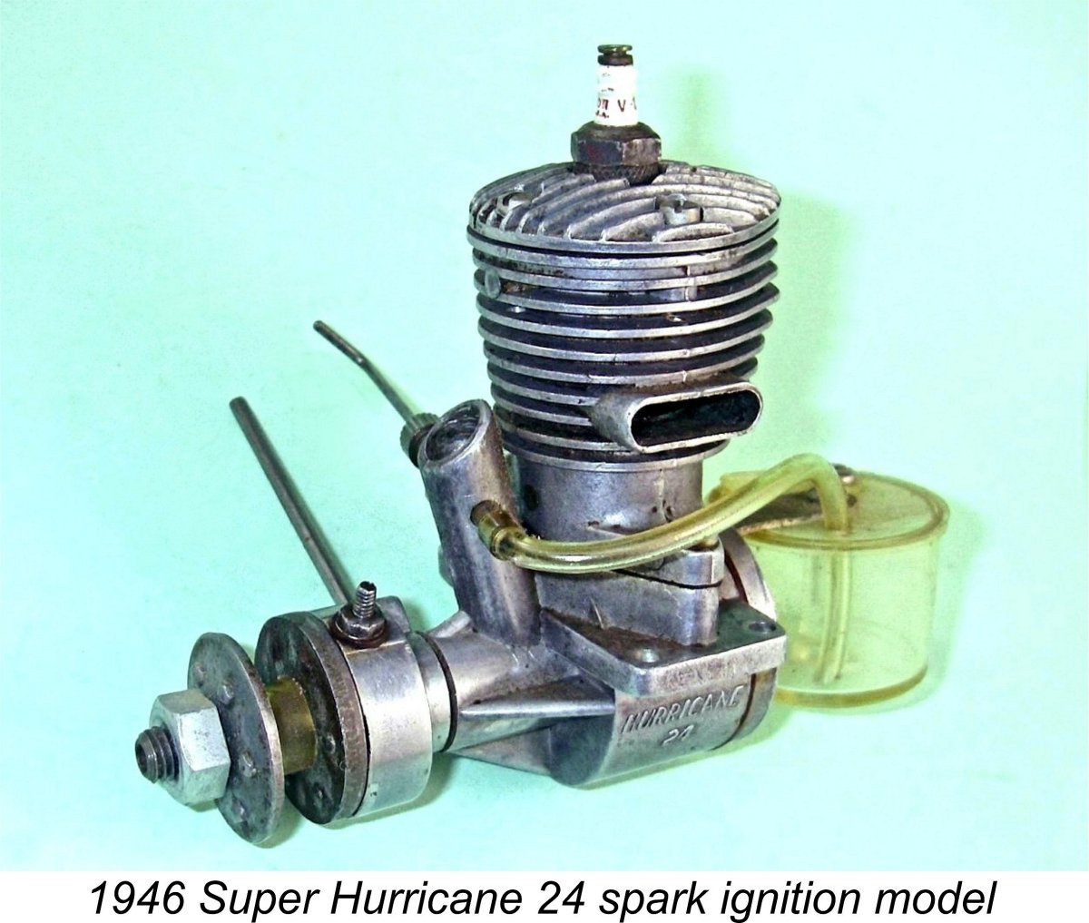
Two further minor variants of the Hurricane 24 followed in 1945, along with a very few examples of a short-lived .198 cuin. spark ignition design which followed a generally similar design layout. In January 1946 the first of three successive “Super Hurricane 24” variants appeared with its “trademark” streamlined cooling fin profile. These Super Hurricane .24 cuin. spark ignition models remained in production into 1948, hence being manufactured in substantial numbers. However, their run came to an end in early 1948 when the advent of the commercial miniature glow-plug and the consequent general This was simply a straightforward glow-plug conversion of the final Super Hurricane sparker. It was basically the same engine with the timer omitted and a metal tank replacing the former plastic item. It was a very serviceable powerplant which performed well by the standards of its day. However, it did not sell in sufficient numbers to ensure the survival of the Hurricane marque – production seems to have ended at some point in 1950. This did not prevent Lawrence H. Sparey from publishing a rather belated test report in the December 1951 issue of “Aeromodeller” magazine, long after production had ceased. Sparey reported an output of 0.279 BHP @ 11,600 rpm, a very respectable performance for a 0.244 cuin. (4.0 cc) glow-plug design dating back to 1948 and running on a low-nitro fuel (Mercury no. 8). Interestingly enough, Sparey commented upon the fact that while currency restrictions had severely limited the number of examples of the Hurricane “Hot Top” reaching Britain, those that had done so seemed to have acquitted themselves well. Sparey made particular mention of one Johnny Jones, who had achieved excellent results in Class B team racing with his “Scramble” design powered by a Hurricane “Hot Top”. Although the Hurricane gave away a full 20% displacement to other competing engines built to the full 5 cc displacement limit, such as the ETA and McCoy 29's, the engine’s fine handling and excellent fuel economy evidently allowed Jones to get away quickly and complete the full five mile heat distance non-stop on a single 30 cc tank of fuel while maintaining an airspeed of around 75 mph.
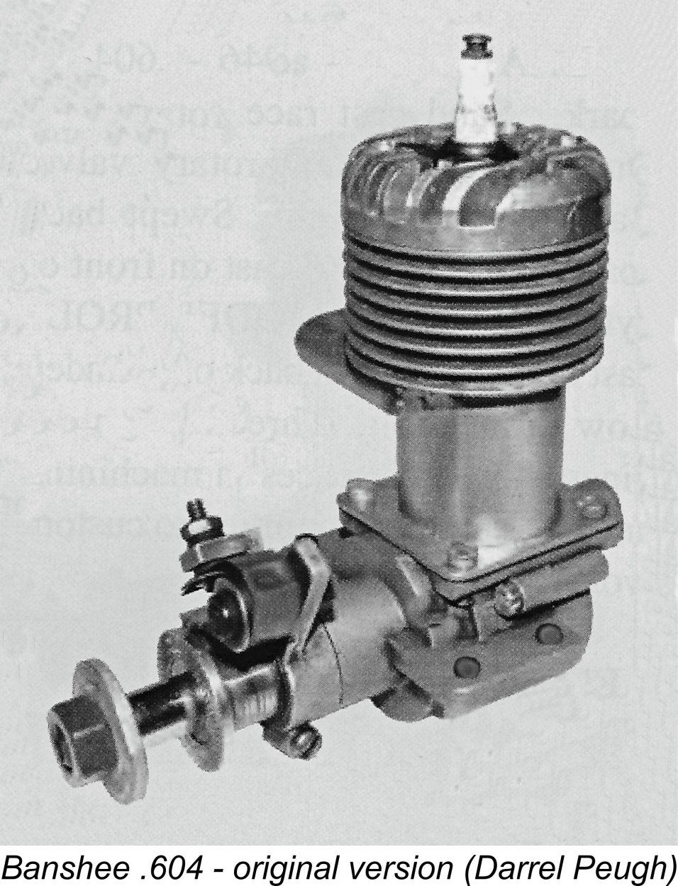
A far less well-known Canadian product was the Banshee .604 cuin. spark ignition racing engine which was mentioned earlier. This disc rear rotary valve (RRV) unit was made in 1944-45 in very small quantities by George Barrett, trading as Barrett Engines of London, Ontario. The engines were distributed by Model Aircraft Hobbies Ltd. of Toronto. For a North American racing engine, the Banshee was unusual in featuring only a single ball race at the rear of the crankshaft. The rest of the shaft was carried in a bronze bushing. Although the absence of a front ball race may seem a little odd in a racing engine context, there was actually sound reasoning behind it. Check out my companion article on the Mamiya range from Japan for a full discussion of this issue. The Banshee has one other claim upon our interest - it was the subject of a "collector's re-issue" by its original manufacturer all of 40 years after its original release! Both original parts and some re- There were a few very small-scale Canadian productions which scarcely seem to qualify for inclusion in a listing of commercial products. A very few examples each of several different CANUCK models were produced in the late 1940's by Lionel Gay and Keith Wooley using the facilities of the AVRO full-scale aircraft plant at Malton, Ontario, where they both worked. Both .049 and .35 cuin. models were made, albeit in far less than commercial numbers - perhaps 12 examples of the .049 and a couple of .35's. Much later, there were also a few high quality team race diesels made by Brian Fairley in a variety of styles. Some of these even bore a maple leaf emblem. Now, having briefly surveyed the Canadian model engine manufacturing scene during WW2 and the subsequent half of the 1940’s, it’s time to return our focus to our main subject, the Monarch 600 racing engine. As a first step in this review, it seems necessary to include some discussion relating to the engine’s date of introduction. The Dating Issue
An on-line investigation reveals that the only present-day Audrey Avenue in Metro Toronto is actually located in Scarborough, a formerly independent community which now forms a major administrative district within Metro Toronto. A quick search using Google Maps revealed that this address is located on a long-established single-family residential avenue, which retains this character to this day. Since Scarborough was a completely separate city during the 1940's, it seems a bit strange that the maker of the Monarch would place his business in Toronto rather than Scarborough. Perhaps he did so because nearby Toronto would have been a far more familiar and hence "mainstream" place name than Scarborough! Alternatively, there may once have been a completely different Audrey Avenue in Toronto proper which has now disappeared or had its name changed. That said, City of Toronto archival records show no evidence of such a street ever existing in Toronto proper - the Audrey Avenue in Scarborough seems to be the only Toronto-area street of that name that has ever existed. Moreover, no-one at the City was able to shed light on the mysterious district indicated by "Toronto 13"! It seems that no such official area designation has ever been assigned at any time ...............
Records held by the City of Toronto indicate that in 1940, 169 Audrey Avenue was occupied by one William J. Shaw, who was still registered as the occupant in 1945. It seems quite likely, albeit unprovable at this point in time, that William Shaw was in fact the maker of the Monarch engines. The City of Toronto's only record of a registered business named Monarch Motors operating at the right time comes from a 1945 business directory. It records Monarch Motors as being a used car dealership operated by Fred McIvor and Alfred Granger at 1616 Danforth Avenue in Toronto, a considerable distance to the west of Audrey Avenue. It seems highly unlikely that this business had anything to do with model engine manufacture, leaving William J. Shaw of 169 Audrey Avenue as our prime suspect. My very sincere thanks to City of Toronto archive staff for their very considerable help in tracking down this information. OK, so now we know where the engine was manufactured, more or less. We even have a highly tentative name for its constructor. Next question – when was it produced? The Monarch was included in both the first and second editions of Tim Dannels’ indispensable “American Model Engine Encyclopedia” (AMEE). However, by his own candid admission to the present writer, Tim had no authoritative historical information whatsoever on the engine. Illustrations of the previously-mentioned examples formerly owned by Ward Hallenberg and Gil Greenberg are featured in both editions of AMEE. Both editions give a date of 1940-41 for the production of the Monarch. I have to say that I immediately found myself entertaining serious doubts regarding the accuracy of this dating. I checked with Tim, who admitted that the dates given were second or third-hand “heard it through the grapevine” figures with absolutely no supporting evidence to back them up. He included them solely because they were all that he had! OK, so let’s consider this issue objectively on the basis of what little additional information is now available. Perhaps most importantly, there’s the evidence provided by the instruction leaflet, which was not available to Tim when he was preparing either edition of AMEE. As of 1940, the market for large racing engines was pretty much confined to the tether car and tethered hydroplane fields. Indeed, even the tether car market was very much in its formative stages – as of 1940, the Hornet 60 from Fresno, California, the Atwood Blue Crown Champion from Glendale, California and the Hassad-built H/S .604 from Maywood, California were the only commercially-available purpose-built large racing engines, and they were all targeted directly at the tether car market (although Bill Atwood did offer a simplified non-racing aero version of the Blue Crown called the Green Crown Champion). However, the Monarch’s instruction sheet specifies the use of a 12 to 13 in. dia. airscrew of 8 in. pitch for free flight, with a 10 in. dia. prop of 10 to 12 in. pitch for control line. The latter sounds very much like a control-line speed prop! No mention is made of car or boat service beyond a passing reference in the Since Jim Walker didn’t apply for his later-nullified US Patent for U-Control until December 1940 (it was actually issued in August 1942 and nullified 11 years later), the above-noted control line prop specification seems highly improbable in connection with a 1940 engine. As of that year, control-line was a mere blip on the aeromodelling radar – very few people even knew about it. Consequently, it’s really hard to see control-line as a potential application meriting recognition in the instructions for an engine released in that year. As far as I can determine, no other manufacturer was featuring control-line as a focused target market at this time or for some years after. Until around 1946/47, the major market for large racing engines like the Monarch was the tether car field, which was then quite popular. Another factor which argues strongly against a 1940 origin is the engine’s use of a ¼-32 short-reach plug thread. While such plugs were undoubtedly introduced before the outbreak of WW2, their use was very largely confined to the relatively small engines which were then just beginning to appear. This was true even in the United States where they originated. It’s very difficult to see a Canadian model engine maker in 1940 electing to use a ¼ inch short reach plug in a new big-bore racing engine given the far greater availability (and durability) of the 3/8 inch plugs then in common use. It was only after the conclusion of WW2 that ¼ inch plugs increasingly became the norm, even in large engines. Another circumstance arguing against a 1940 release (although not prohibitively, recalling the Strato series) is the fact that at that time Canada was deeply embroiled in WW2 as a member country of the British Empire (as it was then). It seems highly unlikely that a Canadian manufacturer would release a new racing .60 in 1940 or indeed at any time prior to 1945 – the attention of Canadians was very much focused elsewhere during this period, while the activities of Canadian precision engineering firms were being Another factor which may speak to the date of the Monarch’s release is the engine’s general design. If it was released in 1940, it would have been among the very first disc rear rotary valve (RRV) racing engines to appear, being preceded only by the Hornet 60 and its direct predecessor, the A.C. Special. This is of course possible, but to me it seems rather unlikely, particularly give the degree of development which seems to be reflected in the Monarch’s design (see below). The Hornet 60 emerged from the WW2 period as still the engine to beat, hence exerting a significant influence upon would-be competing racing engine designers. Even the McCoy 60 as produced by Duromatic Products Ltd. beginning in 1945 was strongly influenced by the Hornet, as were many of the small-scale competing models of the 1945-47 period such as the Batzloff, Atomic, Talisman and Rowell designs.
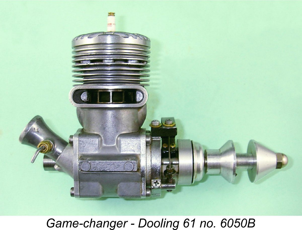
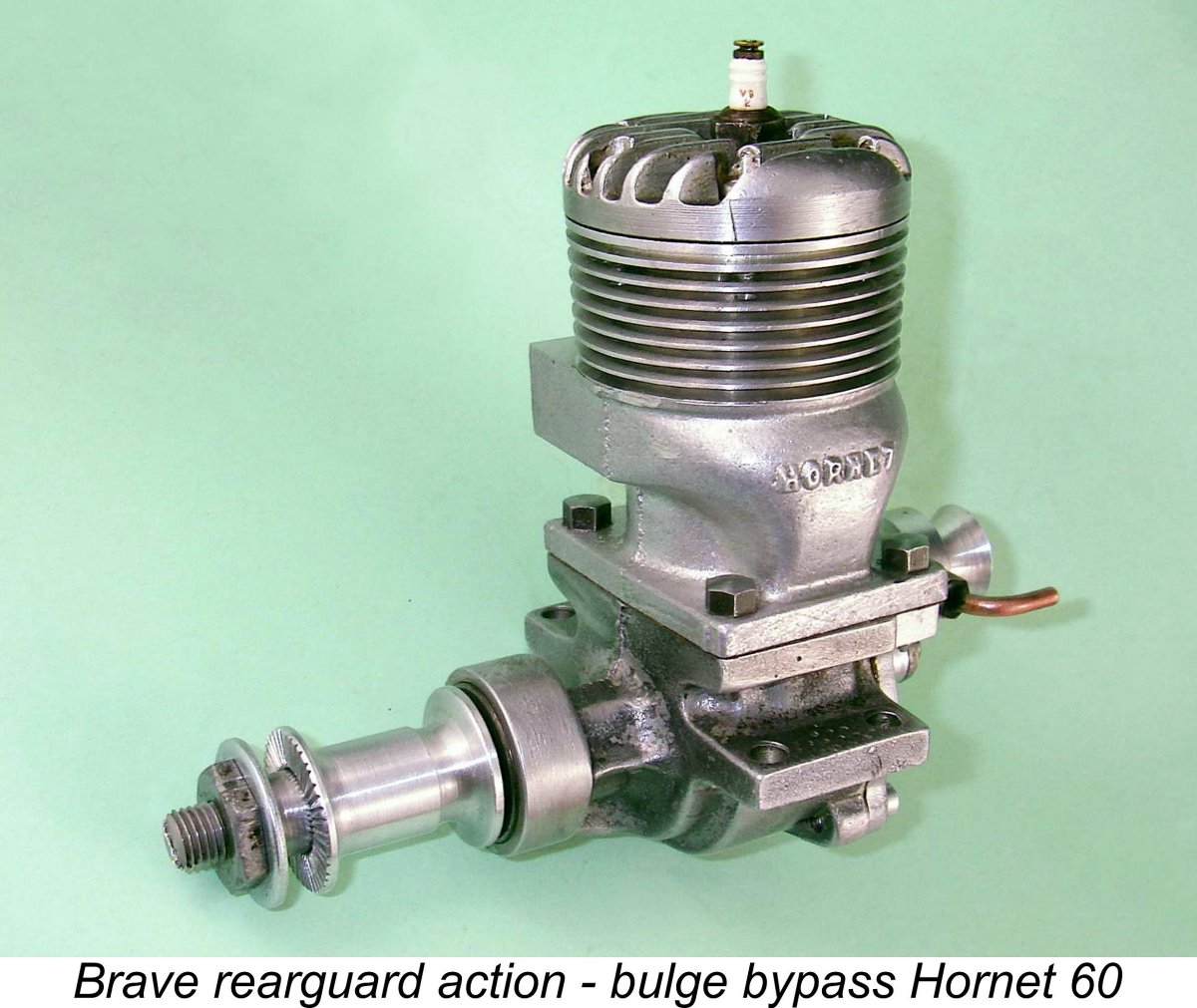
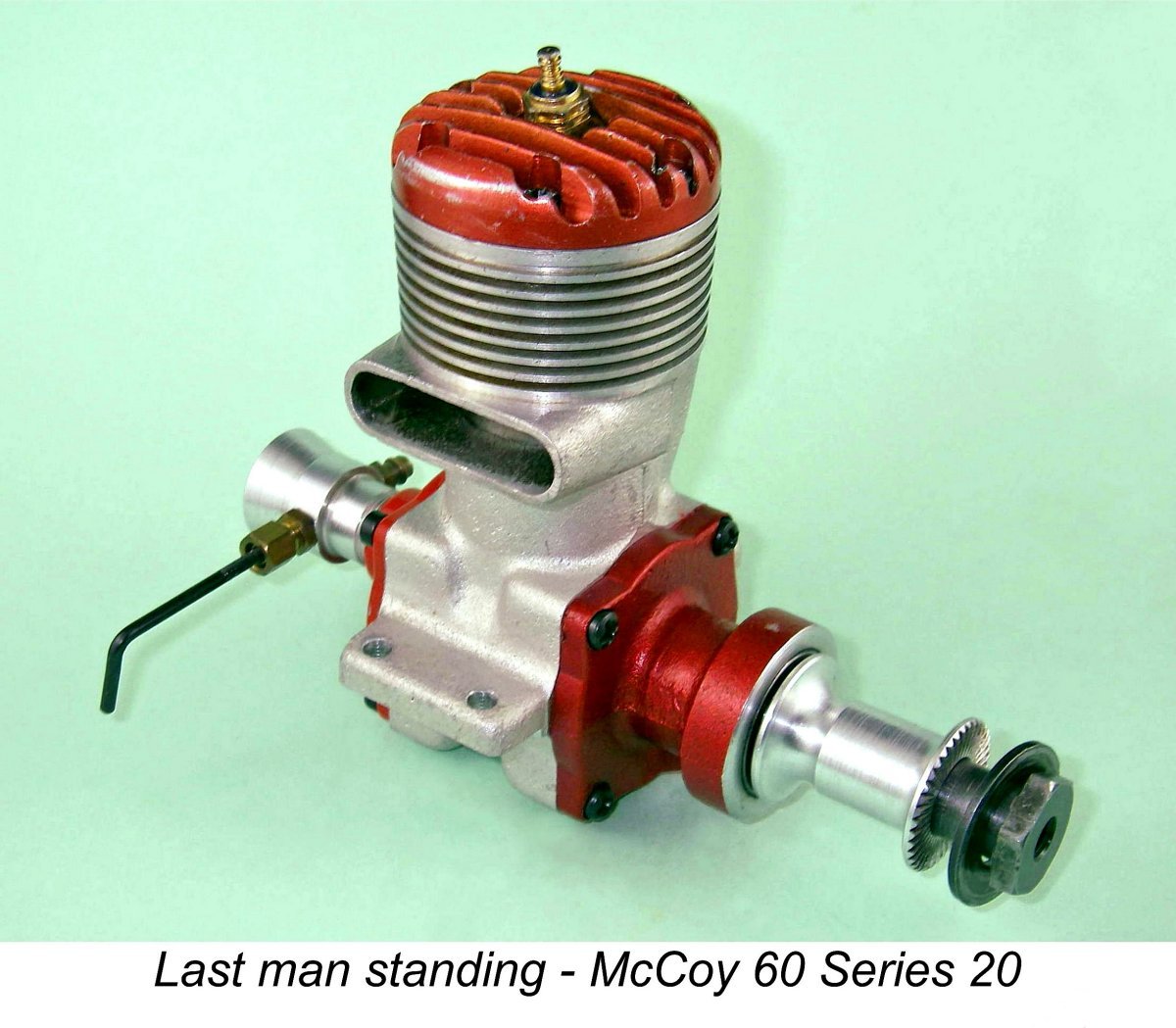
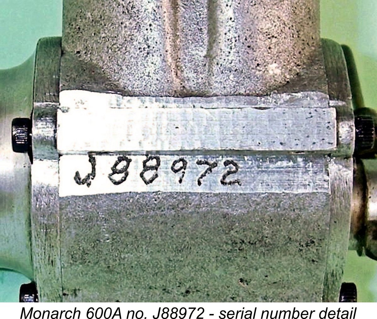
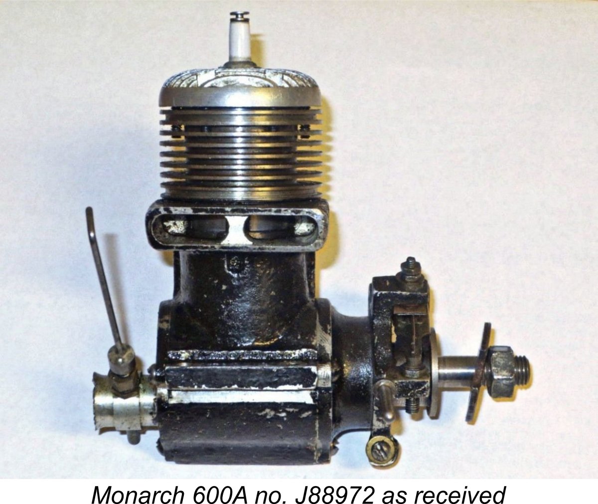
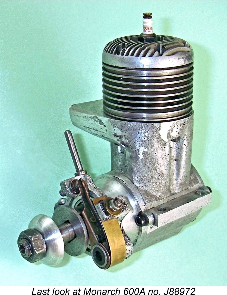
Assuming that this dating can be provisionally accepted as being most probable in light of the above considerations, what about the engine’s withdrawal from production? The event which changed the thinking of racing engine designers overnight by establishing a new performance standard was the mid 1947 appearance of the Dooling 61. At a single stroke, this ground-breaking design rendered all then- Hornet manufacturer Ray Snow responded with a “bulge bypass” upgrade kit for the Hornet 60 which stemmed the tide briefly but could not stave off the final withdrawal of the Hornet in early 1950 after almost a decade of near-dominance. Almost all of the others fell by the wayside too, the sole exception being the McCoy 60 Series 20 which had been developed very rapidly by Dick McCoy in response to the challenge posed by the Dooling 61. Dick's iconic design actually ended up outliving the Dooling model which had prompted its creation. To me, it seems highly unlikely that the manufacturer of the Monarch 600 could have failed to recognize On the basis of all of the above arguments, I personally have little hesitation in voicing my own opinion that the production of the Monarch 600 was most probably confined to the years 1946-47. To me, the evidence of the instruction manual appears to settle this matter conclusively – I can imagine no scenario under which the manual for a 1940 racing engine would include operational guidance for control line aero use. Unless or until persuasive evidence to the contrary comes to light, I will continue to maintain this opinion. The Monarch 600 – Description Here we are on somewhat shaky ground, because there may not have been a “standard” model of the Monarch 600! As stated earlier, only three examples of this engine are presently known to have survived, and only It would appear that the engines all bore serial numbers. That on my example is J88972 which is hand-engraved on the crankcase beneath the left-hand mounting lug. It’s quite evident that this cannot be based upon production figures, nor does it appear to relate in any rational way to a 1940’s date (although I suppose that the final 72 figures could possibly imply February 1947). This being the case, it seems probable that it relates somehow either to the specification of the particular engine involved or to the purchaser of the unit. It’s extremely doubtful that we’ll ever know, although the reporting of additional serial numbers might shed some light upon this matter.
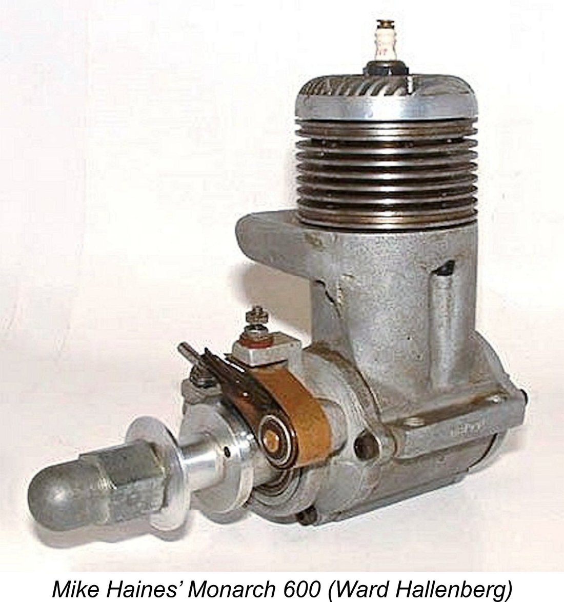
Mike also presented me with the evidence required to correct an apparent error in the record with respect to this engine. In Tim Dannels' invaluable "American Model Engine Encyclopedia" (AMEE), the entry for the Monarch includes images of two distinct engines owned respectively at the time of AMEE's publication by Gil Greenberg and Ward Hallenberg. The unit then owned by Ward Hallenberg was said to be a reed valve variant, while Gil Greenberg's example featured a rotary disc valve. This inevitably forced us to the conclusion that the engine was made available in both reed valve and disc valve versions.
The main point here is that Mike was able to confirm that this engine was in fact a disc valve model just like the two other reported examples. How Ward Hallenberg came to inform Tim Dannels that his engine was a reed valve variant will forever remain a mystery. However, the upshot is that as far as the present evidence goes, we now have no basis whatsoever for presuming the existence of a reed valve version of the Monarch. I must say that I'm not surprised - why would you put a reed valve on a high-performance racing engine like this?!?
This constitutes further evidence to suggest that the engine was produced prior to the arrival of nitromethane on the modelling scene courtesy of the Dooling brothers’ experiments which commenced in late 1947, as documented elsewhere. From 1948 onwards nitro was an almost invariable constituent of model racing engine fuels. According to the instruction sheet, this model was referred to as the Monarch 600A. It's possible that more than one designation was used, but we have no basis for stating this as a fact, nor is it readily apparent why different designations would have been applied to the same basic design. It seems most likely that "Monarch 600A" was the engine's generic name. The use of such a designation implies that the maker had visions of developing an upgraded version of the engine to be called the Monarch 600B. However, there's no evidence to suggest that such a model ever appeared. All known examples of the Mike Haines' example (formerly owned by Ward Hallenberg) features as-cast surfaces, while the engine owned by Gil Greenberg had a black crackle paint finish on all castings apart from the cylinder head. This of course means very little – the black paint could have been removed from Mike's example by a previous owner. Alternatively, the black crackle paint on Gil Greenberg’s engine could equally well have been applied by an owner to give a fashionable McCoy-like appearance. There’s just not enough evidence, and at this point in time we’ll probably never know …………… My own example arrived sporting a rather patchy semi-gloss paint finish on all castings other than the cylinder head. This paint proved to lack any resistance at all to the common solvent materials with which The paint on my engine certainly wasn’t proper engine enamel - it looked nothing like the black crackle finish on Gil Greenberg's previously-illustrated unit. Given the evident care which went into the construction of these engines, I’d be really surprised if our unknown maker used such a paint. I suspect that my engine had a coating of regular paint applied by a previous collector owner simply to give the engine a black-case appearance. Whether or not that appearance is original is a matter for debate, although no final resolution is now possible. The patchy appearance of the paint layer on my example may well be the result of a previous attempt to run the engine, which has undoubtedly been mounted and run in the past.
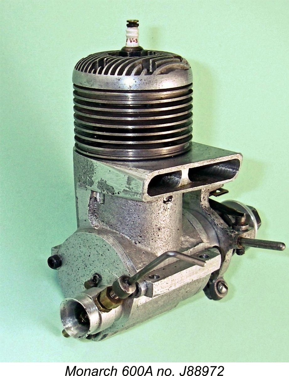
Gil Greenberg’s engine featured a clamp ring to reinforce the securing of the front housing. However, this is absent from either of the other two confirmed examples. It may be original, but it could also be a modification by a previous owner to improve the security of the front housing, which is after all retained by only three screws. Alternatively, it may have been a repair to get around a broken “mouse ear” eyelet. There’s no way of knowing at this point in time. I was able to remove the front and rear covers of my engine fairly easily. I found that no gaskets were used to seal – in typical “racing engine” fashion, full reliance was placed upon finely-finished metal-to-metal joints. I elected not to go further with the disassembly process since I was reluctant to disturb what appeared to be first-class head and cylinder base seals. However, this degree of disassembly was sufficient to facilitate a pretty complete description of the engine. The Monarch 600A is basically a fairly conventional large racing engine of the early post-WW2 period. However, it does display a number of features which imply a considerable amount of original thinking, along with some very precise and painstaking workmanship. First, its internal operating geometry is very considerably over-square, featuring checked bore and stroke dimensions of 24.5 mm and 21.0 mm respectively for a bore/stroke ratio of 1.17:1 and a displacement of 9.90 cc (0.604 cuin.). This is yet another factor which argues strongly against a 1940 origin – engines of such significantly over-square dimensions were far from common at that time. Even the iconic Hornet 60 racing engine with its bore and stroke dimensions of 23.87 and 22.22 mm respectively (ratio 1.07:1) didn’t match those figures. The Monarch actually lay midway between the Hornet and the later Dooling 61 in this respect. Its geometry would have been viewed as extremely radical in a 1940 context. The engine weighs in at 429 gm (15.15 ounces), complete with plug and timer. This is a pretty average figure for a 10 cc racing engine of the period – in fact, it’s actually lighter than some.
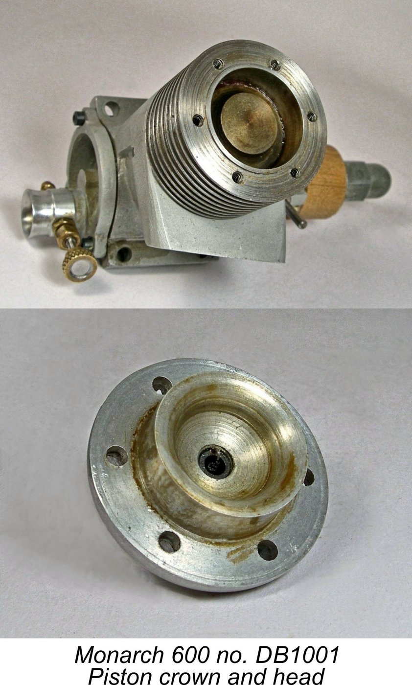
The head is secured to the top of the steel cylinder with six 4-40 Allen-head screws. Initial impressions to the contrary, these screws are only long enough to fully engage with the corresponding relatively short tapped holes in the upper cylinder flange – their sole function is thus to secure the cylinder head. The compression ratio generated by the head on my example is unusually high – around 11:1 by direct volumetric measurement. You certainly feel this when flipping the engine over! Such a high compression ratio implies an expectation that the engine would be operated primariy on a methanol-based fuel. The steel cylinder itself is provided with integrally-machined cooling fins. Rather unusually, it is retained by four more 4-40 Allen-head screws which are inserted from below and pass upward through holes in the I’m unable to provide any images of the piston in my example since I chose not to disturb the cylinder/head assembly. However, inspection through the very large exhaust ports and the crankcase confirms that the piston is formed as a rather complex iron casting, complete with internal gudgeon (wrist) pin bosses of substantial length as well as a high domed baffle piston crown looking very much like that used in the Hornet and McCoy 60 models. The walls of the piston are quite thin, implying a relatively low weight for a cast iron piston of this size. The fit of the piston in the bore is truly superb – a near-perfect compression seal with only the slightest sign of pinch at top dead centre. The visible surfaces Engine number DB1001 now owned by Mike Haines features a completely different piston configuration. There is no baffle, the high crown simply extending uniformly around the entire piston circumference. This high crown presumably performs the function of the baffle, which had evidently been found to be unnecessary. The head is provided with what amounts to a squish band around its outer edge. This should combine with the piston crown to create excellent swirl within the combustion chamber, also promoting the concentration of the mixture near the ignition source to facilitate more rapid combustion. It must be said that this is a very advanced design indeed for an engine dating from the 1940's. The engine’s porting arrangements are a little unusual. The exhaust porting consists of two neatly-cut rectangular openings of generous dimensions which discharge into a pair of separate ducts formed by milling inside the exhaust The crankcase is a relatively complex sand casting which has clearly received a good deal of careful hand-work to remove flashing, burrs and the like. It is a little rough in terms of its surface finish but appears to be perfectly sound. A point of great interest is the configuration of the exhaust stack outlet. The outer face of the stack is angled both rearwards and downwards. This may be clearly seen in a number of the attached images. I though at first that this might be an owner modification, but in fact the outer edges of the stack retain their as-cast surface finish with no evidence of sawing, milling or filing. I also note that both Mike Haines' and Gil Greenberg’s examples appear from the photographs to have similarly-configured stacks. It would seem that this was the standard configuration as supplied by the manufacturer.
The port timing is once again of some interest. The exhaust port opens at 110 degrees after top dead centre (ATDC) for a total exhaust period of 140 The piston drives the crankshaft through a sand-cast alloy conrod of quite generous proportions. All fits are excellent, with absolutely no detectable play in the assembly. I can’t comment on the small end since I didn’t dismantle the engine sufficiently, but the big end is bronze-bushed. The finely-finished crankpin has a generous diameter of 0.312 in. (5/16 in., or 7.94 mm). The crankshaft seems to be a composite construction of some kind. The heavily counterbalanced crankweb appears to be mounted on a spigot extending rearward from the main journal forward of the web. I was unable to shift the crankshaft rearward in its bearings using fair means, hence being unable to report in detail on the approach taken to securing the web to the main journal. The shaft runs in two closely-fitted ball bearings. These are Norma-branded items of American manufacture. They are mounted in an extensively-machined front housing The timer cam is ground into the rear of the hardened steel prop driver, which is keyed to the shaft through having a square-section central hole closely corresponding to a square male section of the crankshaft immediately forward of the main journal. There are four possible prop driver mounting orientations using this system, which thus allows the owner to orient the timer in any desired configuration to suit the model installation. An issue which immediately rears its ugly head is the fact that the front face of the prop driver is devoid of any knurling or grooving which would promote a good grip between the driver and an airscrew. Given the high torque figures developed by engines of this sort, prop slippage might well be an issue with this unit as received, particularly during hand-starting. It would probably be necessary to glue a disc of coarse sandpaper onto the front of the prop driver to overcome this problem.
My own engine arrived with a plain steel nut and a somewhat graunched steel washer which I’m certain was an owner replacement. I elected to make a “look-alike” domed washer along the lines of that featured on Gil Greenberg’s example. There is of course no way of knowing which of these styles are correct – it’s quite possible that both styles may have been used on different examples. The timer is an essentially conventional design by mid 1940’s standards, being based on a set of standard automotive points. The sand-cast frame is unusually lightweight in section – I’d caution owners to handle this component with great care. My newly-acquired example had a cracked clamp lug which I secured using the ever-dependable JB Weld. The timer mounts on a shoulder which is machined into the front of the main bearing housing.
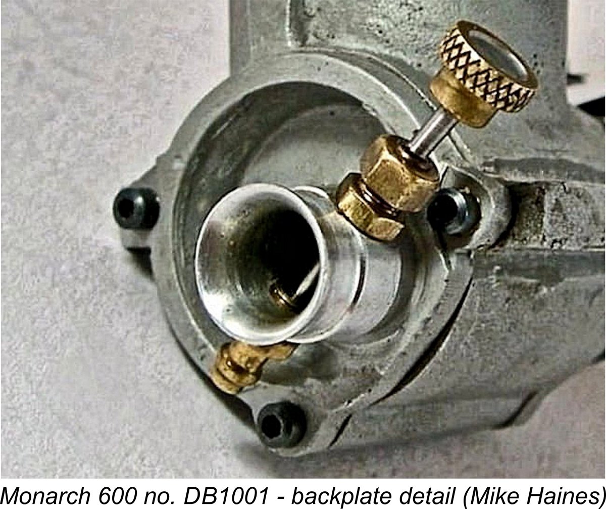
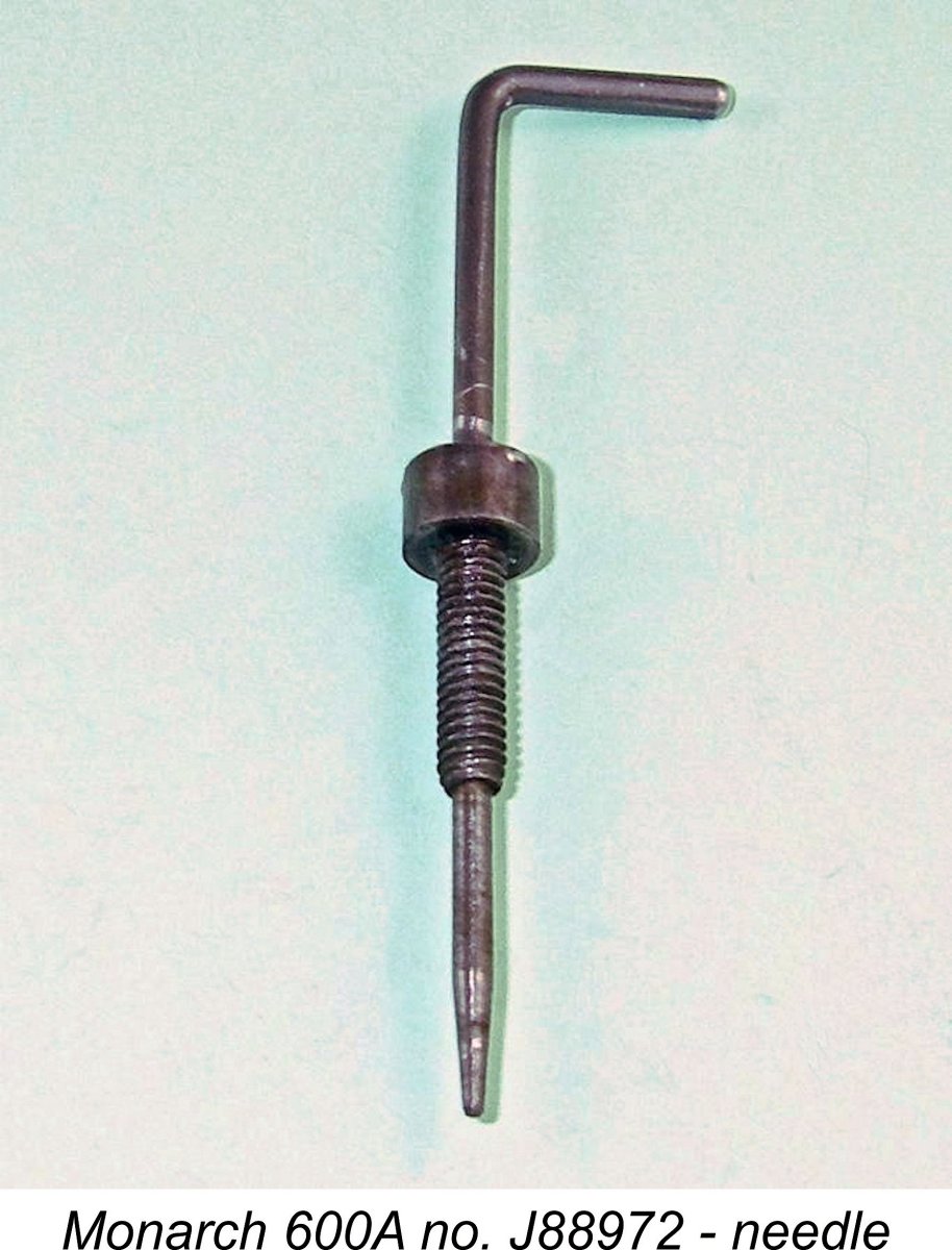
The induction hole in the backplate is a perfectly round drilled aperture having a very generous internal diameter of 0.375 in (3/8 in. or 9.52 mm). It is a close match for the kidney-shaped induction port in the disc valve itself, opening and closing quite rapidly. Timing is fairly conventional, although it could of course The backplate itself is another noteworthy component. It appears that two distinct light alloy sand-castings were used to generate different versions of this component. The examples formerly owned by Ward Hallenberg and Gil Greenberg both used what appears to be the same casting having a recessed rear face apart from the necessary boss to accommodate the intake. This casting placed the intakes of both versions in the lower right quadrant of the backplate (viewed from the rear). The backplate of my example is also produced from a high-quality sand-casting. The original as-cast surface is visible in a couple of pockets incorporated into the front face behind the disc valve, presumably both to serve as oil reservoirs and to reduce friction and viscous drag. However, the rear face of the component is not recessed, being machined all over. The casting has also been subjected to a considerable amount of careful hand work. As with the front housing, the profile of the backplate mounting flange has been Of even greater interest is the fact that the intake venturi on both variants is machined in one piece with the rest of the component using an eccentric work setting. Its previously-noted internal diameter of 0.375 in (3/8 in. or 9.52 mm) works in conjunction with a conventional Hornet/McCoy style surface jet needle valve assembly to offer minimal air flow restriction through the venturi. It’s clear that suction draw with such a wide-open system would be marginal at best. Small wonder that the instructions specified the need to arrange for gravity fuel feed! The location of the intake in the lower right quadrant of the backplate (viewed from the rear) may well have had the objective of facilitating the provision of gravity fuel feed when the engine is mounted in an upright or sidewinder orientation. It also The tapped holes for the needle valve assembly are drilled through the intake venturi at a 45 degree upward angle to the right (viewed from the rear). Since the integrally-machined venturi can’t be re-positioned, this means that the owner is stuck with this needle orientation regardless of any model constraints. The needle and fuel pickup can be switched around for sidewinder mounting, but that's it. A good design feature of the 0.074 in. dia. needle is the fact that it is mounted in a separate body having a relatively large-diameter threaded portion, thus creating a far more stable and wear-resistant system than would be the case with a directly-threaded needle. It is tensioned with the usual racing engine split carrier/gland nut combination. Overall, we have here a well-executed and quite original design presenting some unusual features along with a very high standard of workmanship, especially where it counts. The Monarch really does credit to its unknown designer and builder. Each example appears to have received far more than the usual amount of individual attention for a commercial product. Conclusion
However, I have elected not to put this particular engine into the test stand. This decision was based in large part on my inability to fully assess the crankshaft’s durability. I also took account of the questionable integrity of the cast alloy rod (not a good choice for a high-compression racing engine) and seemingly flimsy timer frame with its repaired clamp. It would probably be OK, but you never know..........anyway, conservation is critical when dealing with an engine of this rarity, and an assessment of its performance would really do nothing more than satisfy curiosity. Not worth the risk of damaging something this rare in my view. Quite apart from the conservation issue, there was also the matter of the plain prop driver surface to which attention was drawn earlier. Past experience with large high compression racing engines displaying such a feature has not been positive – prop slippage can be chronic due to the high torque figures involved. There are ways around this, but once again – why bother? Mike Haines tells me that curiousity led him to give his example number DB1001 a few runs after he received it from America. He didn't take any RPM figures in deference to the engine's obvious age and suspected rarity, but it was clearly a very potent unit. He particularly recalled it as having been the loudest engine that he had ever run, putting his example of the infamous Yulon 49 in the shade! The engine survived the running that he gave it, so presumably the components are up to their tasks. Anyway, there we have to leave it. At least I’ve hopefully been able to do something to bring this generally-overlooked high-quality Canadian racing engine out into the light. I hope that a few more examples may surface as time goes by. If so, I’d be delighted to receive further information! In particular, more serial numbers would be of the greatest interest ……… ____________________________ Article © Adrian C. Duncan, Coquitlam, British Columbia, Canada First published February 2018 Updated May 2018 - info from Mike Haines |
 Looking over the contents of this website in late 2017, I found to my chagrin that I had yet to feature a Canadian engine in these pages. Given my long-time residency in Canada, I thought that it was about time for me to remedy that deficiency! I decided to do so by presenting what little can be learned about one of only two classic racing engines to originate in Canada, the almost completely forgotten 10 cc Monarch 600 spark ignition unit from Toronto, Ontario. The only other classic Canadian racing engine was the Banshee .604, of which more below in its place.
 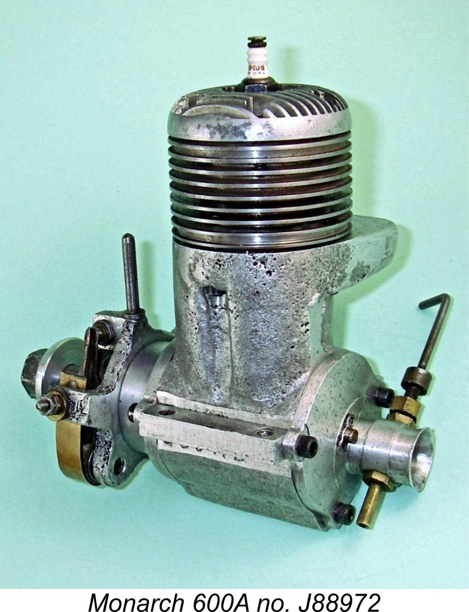 For my own part, I certainly never expected to have the opportunity to examine and test an example of this very rare unit. However, a nice used example appeared out of the blue on eBay in November 2017. The seller was located in the engine’s hometown of Toronto, Ontario, so it apparently hadn’t travelled very far during its 70 year lifetime up to that point! The seller informed me that he had acquired the engine only a year or so before from a hobby shop in Barrie, Ontario (a little to the north of Toronto), which had a sideline trading used modelling items. He had no knowledge of the engine's previous history - that trail is cold.
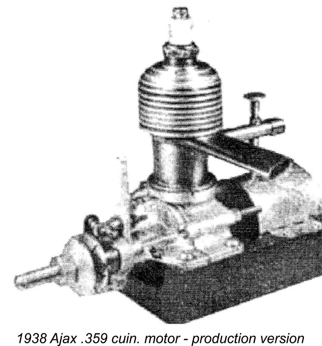
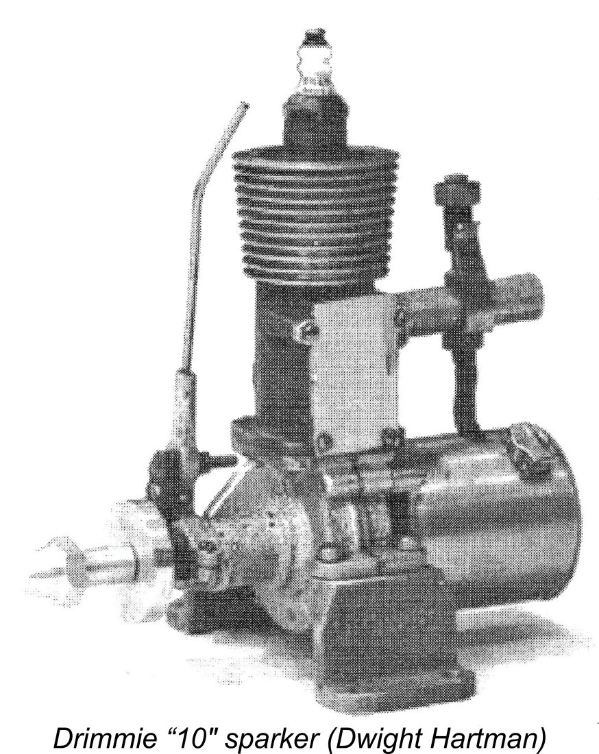 Despite this involvement, an enthusiast named Paul Drimmie of Toronto, Ontario somehow managed to produce a very small number of examples of a 0.607 cuin. (9.95 cc) sideport spark ignition engine called the Drimmie ”10” in 1940. However, this effort ended almost as soon as it had begun, doubtless due to the intrusion of other more pressing concerns. It seems that Drimmie never resumed model engine manufacture after the war.
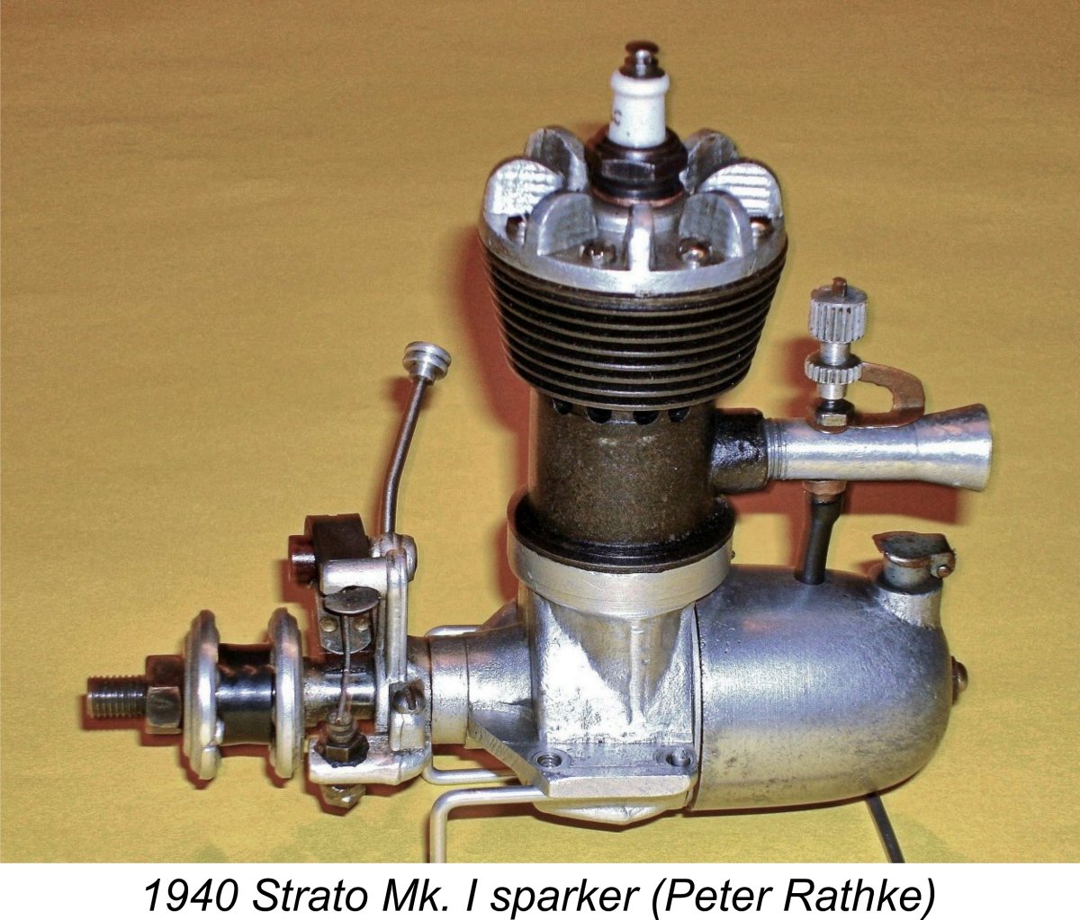
 Out on Canada’s West Coast, the
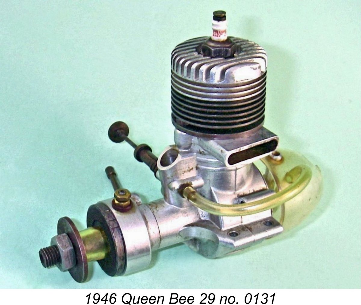
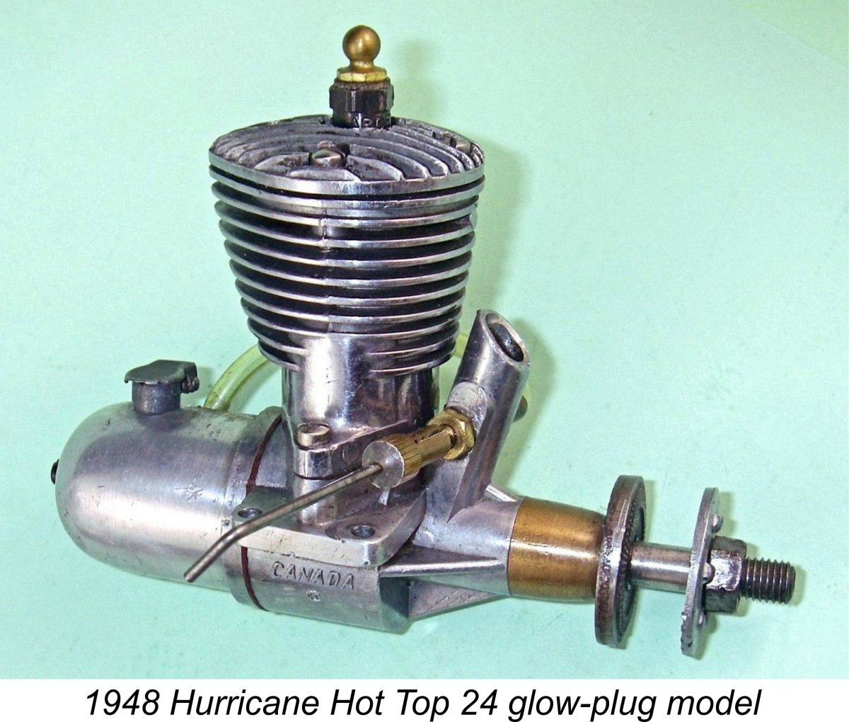
 In the interests of conservation, I should take this opportunity to point out that many examples of the Hurricane “Hot Top” have been damaged by ill-informed attempts to remove what appears to be a slip-on bronze cam cover at the front of the main bearing, the intent being to retro-fit a timer. In reality, this
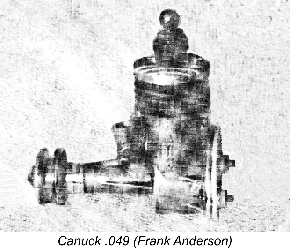
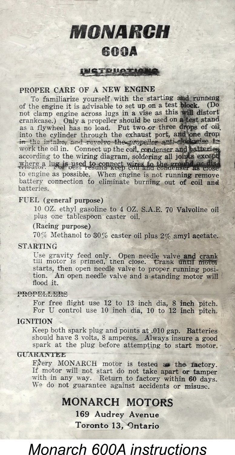
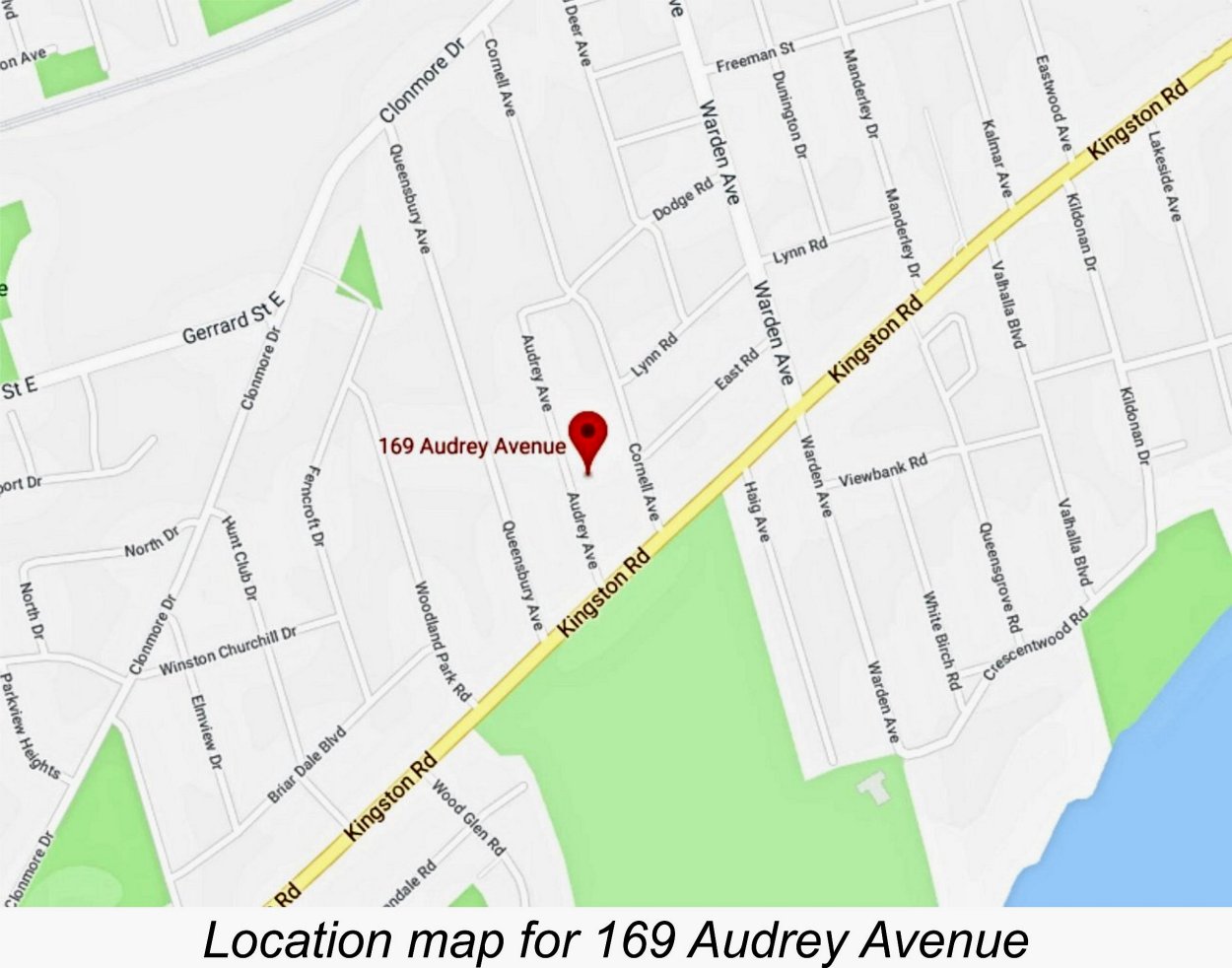 According to the instruction leaflet which fortuitously still accompanies this example of the Monarch, the engine was manufactured by Monarch Motors of 169 Audrey Avenue, Toronto 13, Ontario, Canada. The engine is actually referred to on the instruction sheet as the Monarch 600A.
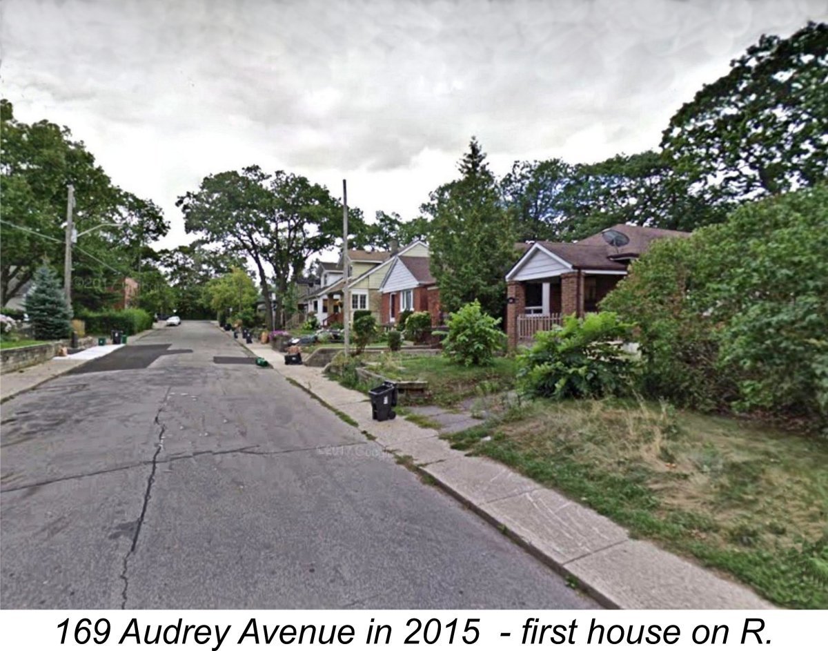 If the Scarborough address is indeed the correct location, it would seem that either the engines were made elsewhere and marketed from the Audrey Avenue residential address, or (in my view far more likely) the engines were made at that address by an artisan producer working in the proverbial “garden shed” or basement workshop. The seemingly miniscule production seems entirely consistent with the latter hypothesis. The engines never appear to have been advertised nationally, implying that they were made in very small numbers purely to serve the Toronto-area market. It’s quite likely that they were marketed by word of mouth and individually constructed to special order.
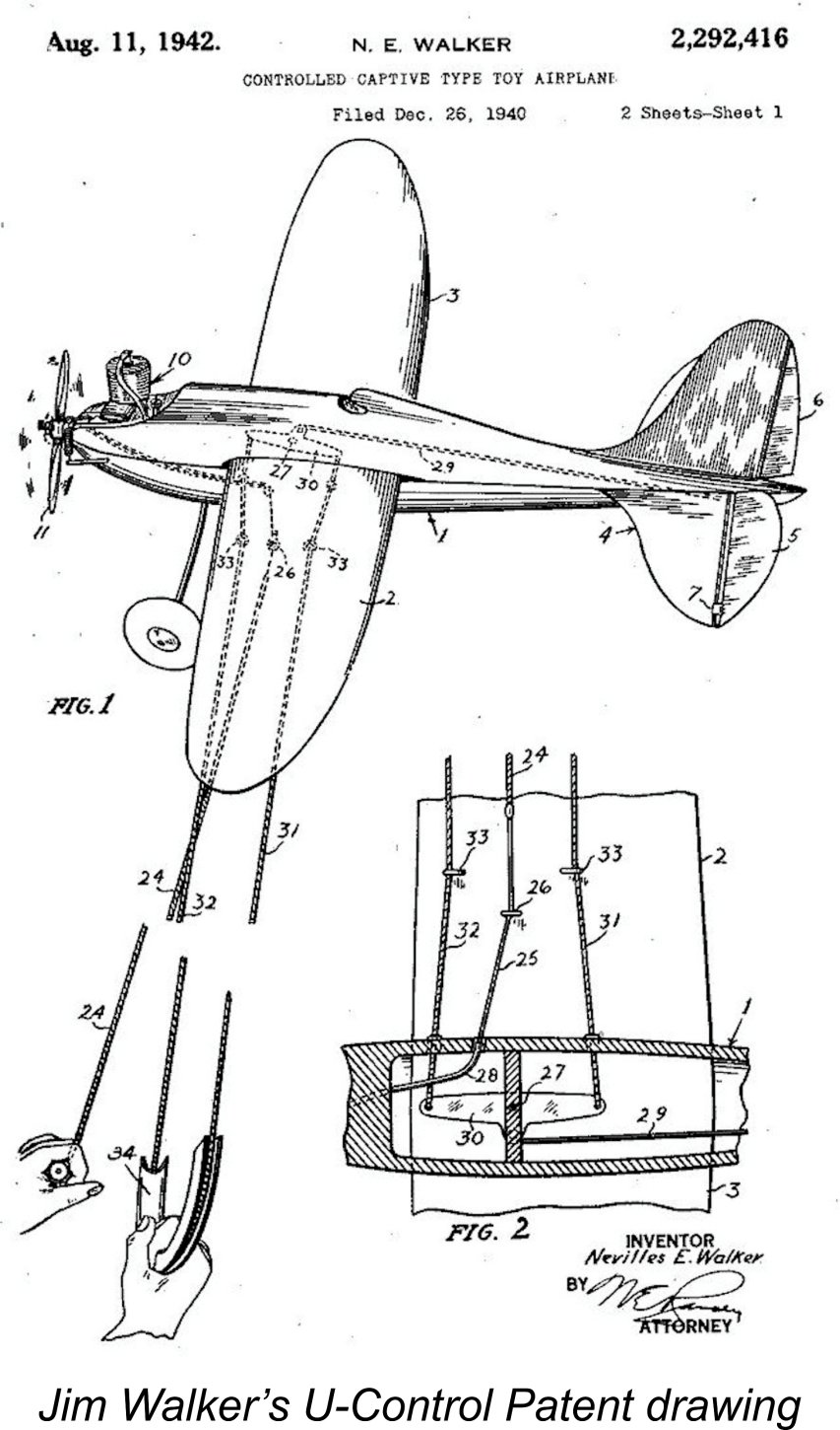 instructions to the effect that bench running with a flywheel should be avoided due to the risk of over-speeding. This clearly indicates that the aeromodelling sector was the primary target market for the Monarch. In the context of large racing engine production, this didn’t become a viable market until 1946-47 at the earliest.
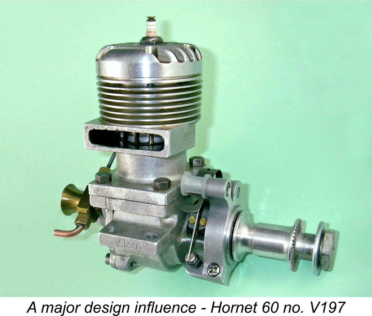
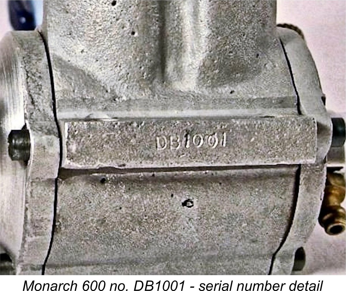 In that regard, I was delighted to hear from reader Mike Haines of Worcestershire, England, who reported that he owned engine no. DB1001 which he obtained a few years ago from a now-deceased US collector. Unlike my example, Mike's engine is stamped on the outer end of the left-hand mounting lug. I can see absolutely no connection between these two numbers, making it appear that there wasn't any kind of logical sequence involved.
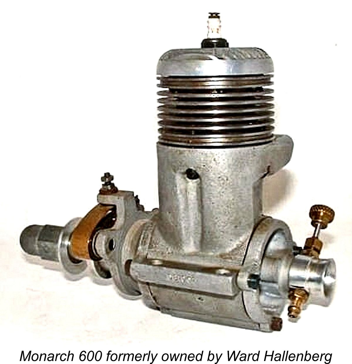
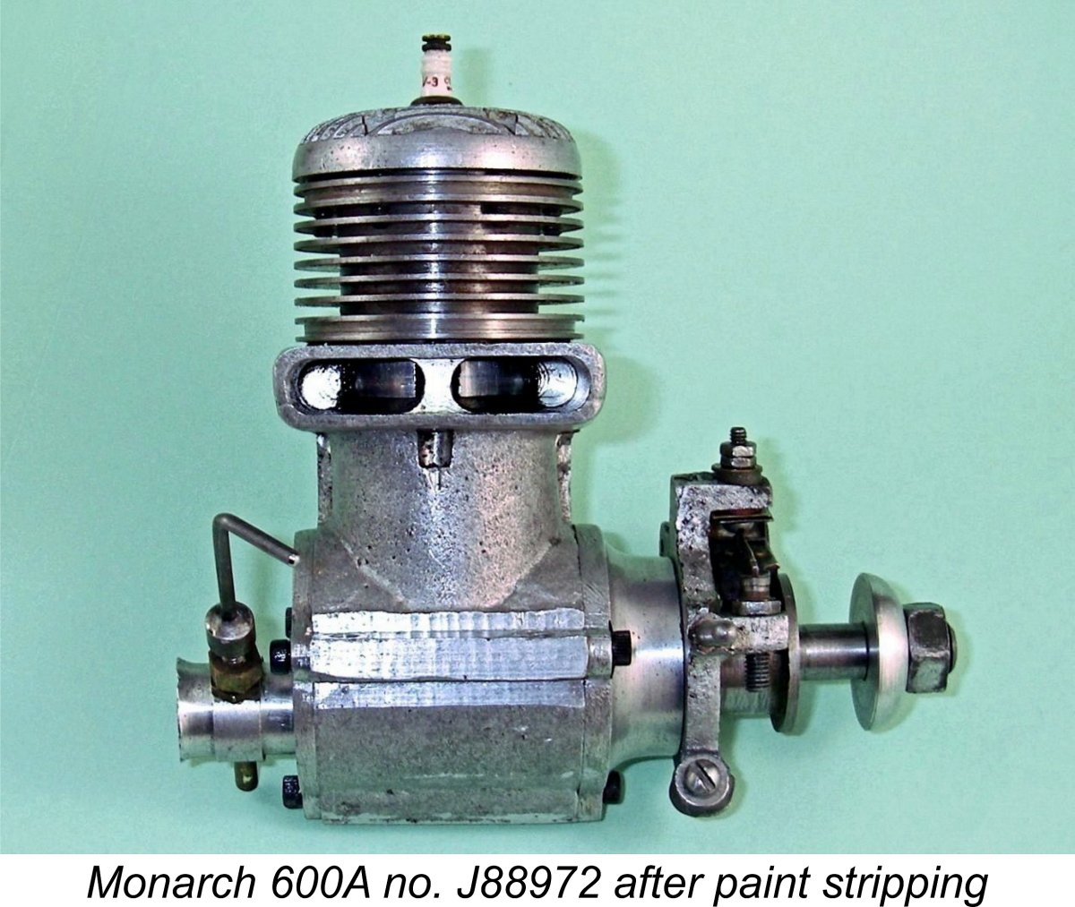 Given the chronic instability of the paint on this example, I elected to remove it entirely, thus making the engine “fuel proof”. This simply involved soaking the parts in methyl hydrate for a few minutes, after which the paint simply flowed off easily using a toothbrush! The plain as-cast surface proved to be of more than acceptable quality. I actually prefer engines with unpainted castings – the paint inevitably chips or wears off, imparting a very "battered" look. Any future owner of this engine will of course be at liberty to re-paint it using proper solvent-resistant engine enamel!
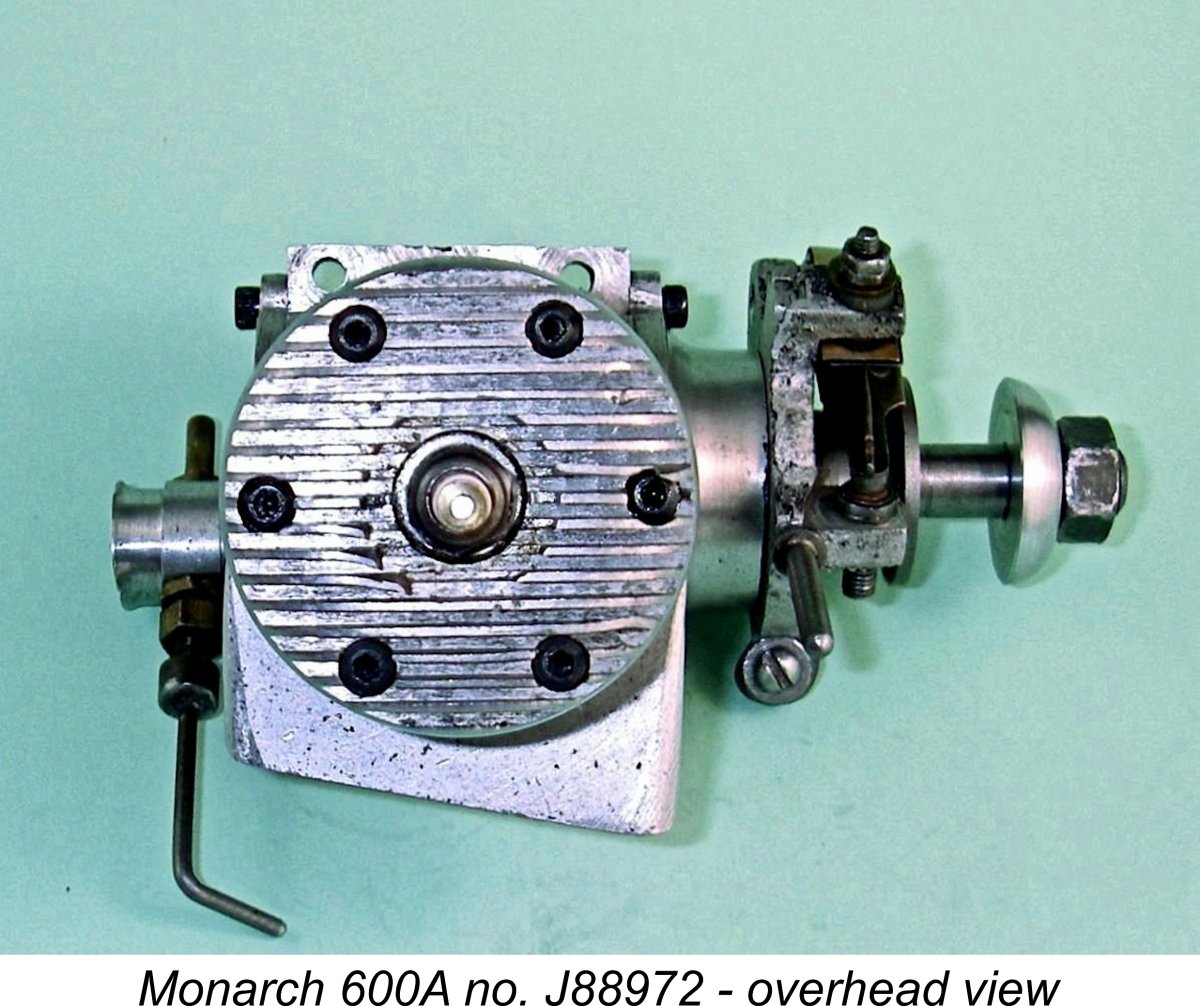 The cylinder head is very nicely machined from a light alloy sand casting. It incorporates a centrally-located ¼-32 plug installation thread – another indicator of a probable post-WW2 origin as noted earlier, since the vast majority of large pre-war engines used
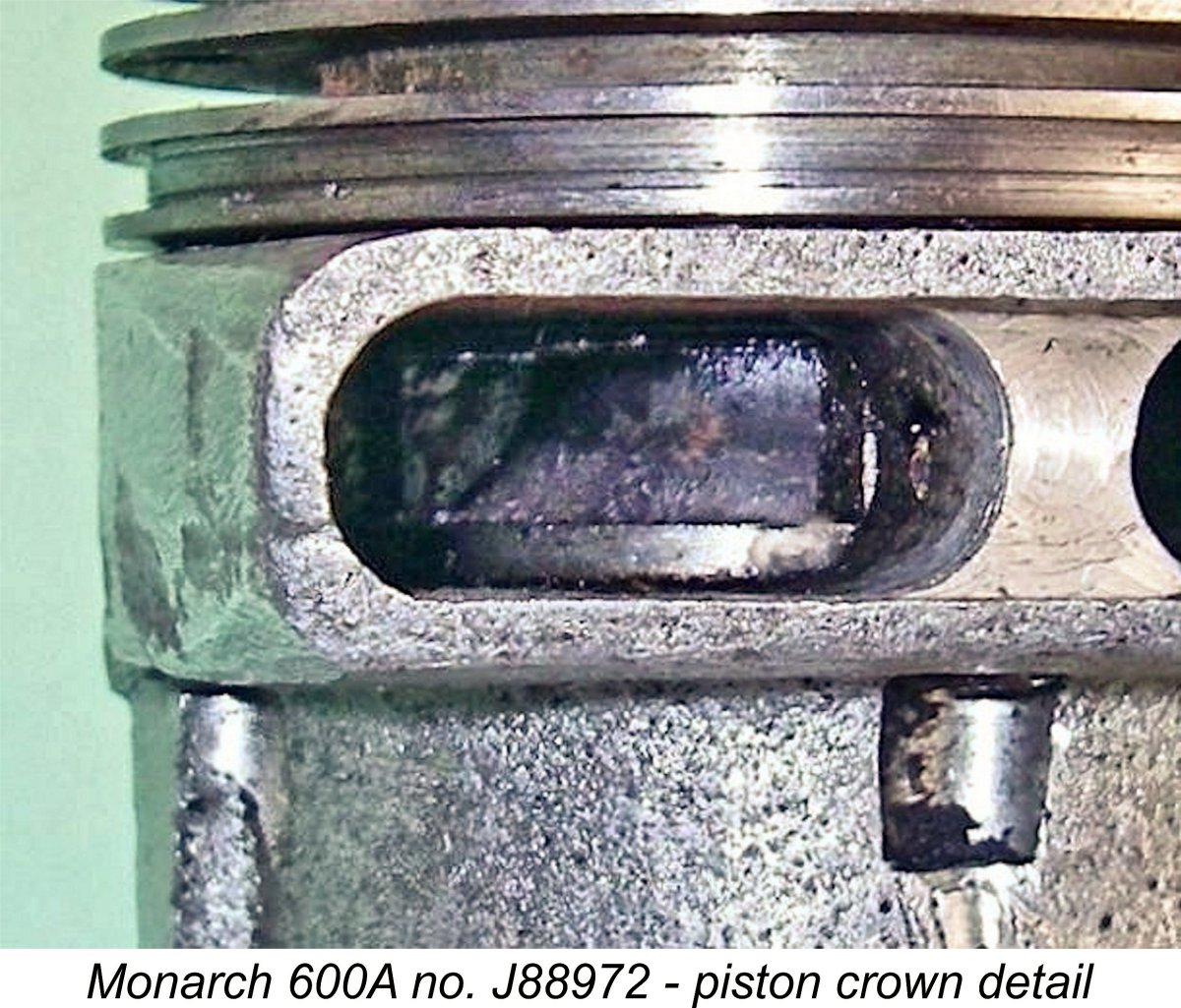
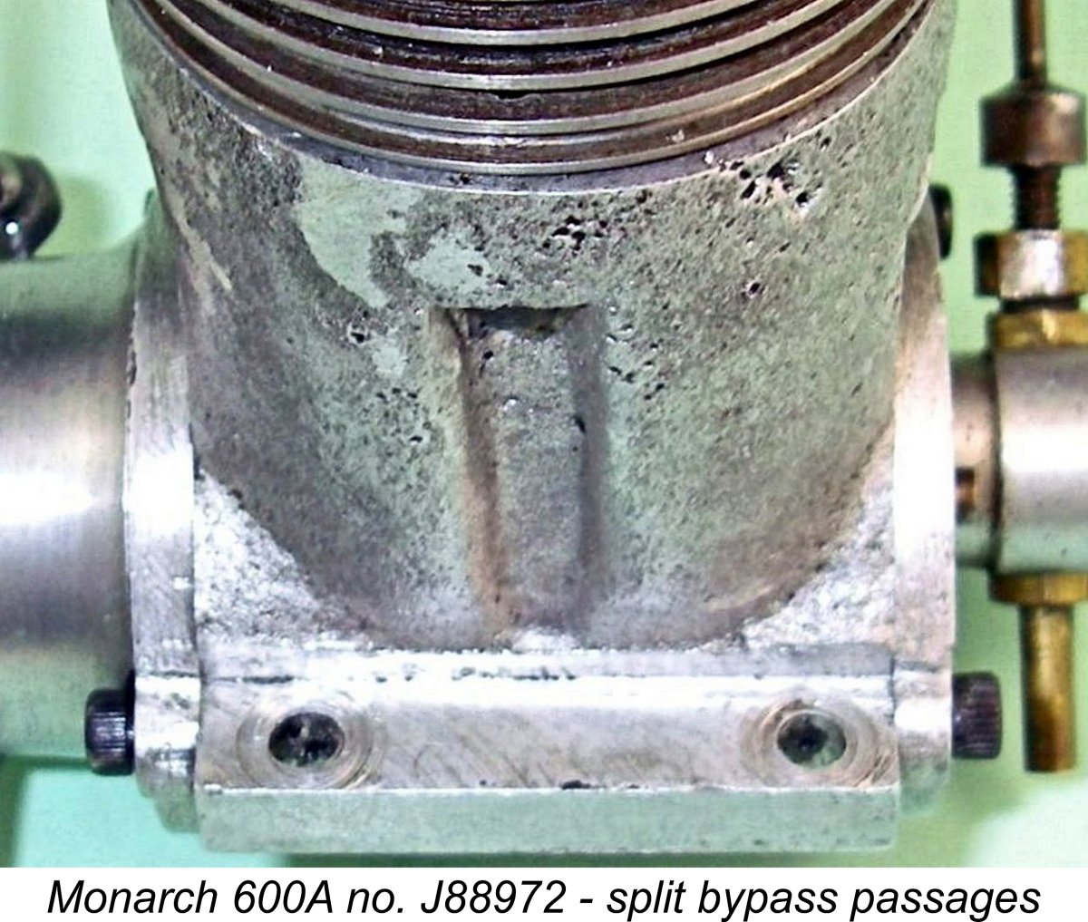 Of equal interest is the transfer porting. The bypass “bulge” in the upper crankcase casting is divided into two parallel bypass passages radially spaced roughly 60 degrees apart, once again to leave sufficient material between them to accommodate one of the cylinder hold-down screws. Each of these two bypass passages supplies its own rectangular transfer port. To some degree, the arrangement actually foreshadows the system pioneered in 1956 by Enya with their
 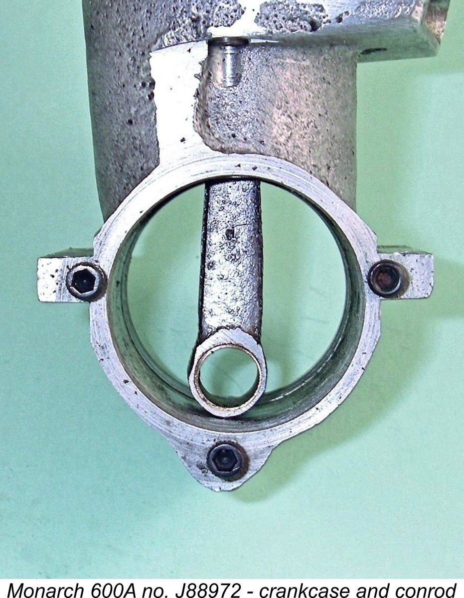 degrees of crank angle. Somewhat unusually for the period, the transfer ports open only some 5 degrees later for a very short 5 degree blow-down period and a lengthy 130 degree transfer period. These are quite aggressive figures, particularly for the mid 1940’s. There is no sub-piston induction on my example.
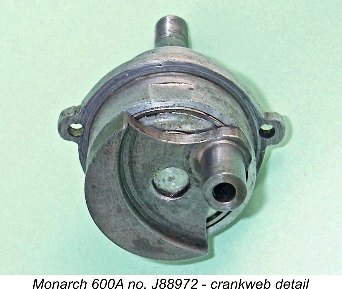
 Two distinct prop retaining configurations have been documented. Mike Haines' example (formerly owned by Ward Hallenberg) features a nicely-machined bullet-shaped spinner nut with an aluminium washer, while the previously-illustrated unit owned by Gil Greenberg used a plain steel nut with a thick dome-shaped aluminium washer.
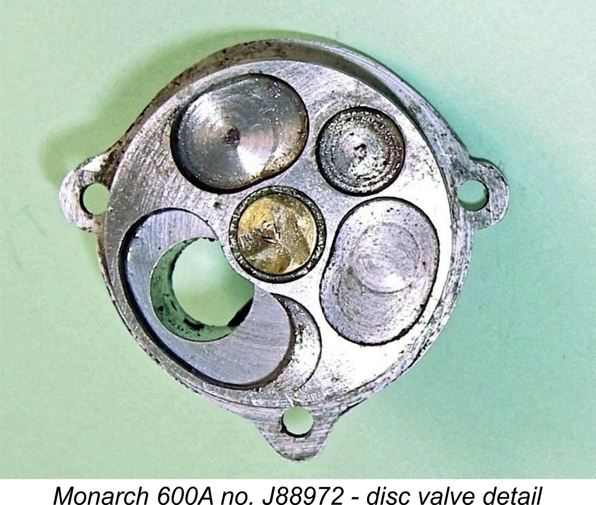
 be easily modified by an owner if desired. As supplied, the induction opens at 45 degrees after bottom dead centre (ABDC) and closes at 30 degrees ATDC for a total induction period of 165 degrees.
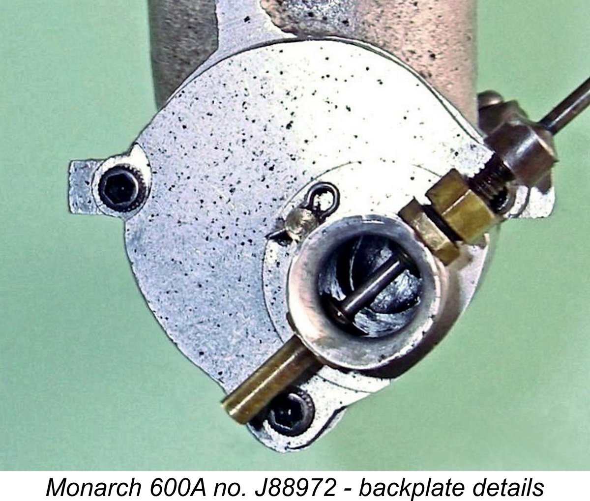
 As noted earlier, the preponderance of cumulative evidence suggests a production period for the Monarch which lay somewhere between 1945 and 1947. Looking at the design objectively, I would expect it to deliver a fairly sprightly performance by the standards of that period.
| |