
|
|
A London Rarity - the Comet 0.4 cc Diesel
I’ve previously covered the Comet in an earlier article which appeared in October 2012 on the late Ron Chernich’s ever-engaging “Model Engine News” (MEN) website, where it may still be found. So why the re-publication here?!? Simply because my mate Ron unfortunately left us in early 2014 without sharing the access codes for his heavily-encrypted site. Because no maintenance has since been possible, the MEN site is slowly but perceptibly deteriorating - an inevitable process which can have only one ending in the long run. I was unwilling to risk the loss of the information so painstakingly gathered on the little Comet, hence the article’s re-publication here. This is one of those subjects about which almost nothing of substance appears to have been recorded, either in contemporary sources or latter-day writings. Accordingly, I'll pretty much have to make do with what little can be gleaned from the few available advertisements together with a close examination and test of an actual example. Let's see how I get on ................ Background
Following the conclusion of the war, information regarding this new form of model power unit quickly spread to England. Much was learned from examples of model diesels brought back to Britain by returning servicemen who had acquired them while serving in countries such as France and Italy where model diesels had been developed during the war years. Initial development in Britain was carried out almost exclusively by the model engineering fraternity - the Motor Boys of their day. An article by pioneering British diesel experimenter and later engine tester Lawrence H. Sparey appeared in the December 1945 issue of “Aeromodeller” magazine under the title "The Gen on Diesel Engines". This article proved to be highly influential in stimulating the further development of the model diesel concept in Britain.
Progress was rapid, the result being that within a year or two the best British diesels were well up to par with the majority of their Continental rivals. This chain of events initiated the love affair between British modellers and the model diesel engine which was to endure for the following three decades or more. For some of us, the affair has never ended! One of the great advantages of the model diesel over its spark-ignition counterpart was its potential for construction down to extremely small displacements. The absence of the complex, heavy and frequently undependable ignition components as well as any form of plug were the keys to making this possible. The consequent potential for sub-miniaturization was quickly recognized, with experiments soon getting underway to probe the lower limits of practicable construction. An article describing these efforts in some detail may be found elsewhere on this website.
This incredible little creation was claimed at the time (probably quite justifiably) to be the smallest operating I/C engine in the world. Fjellström backed up this claim by making frequent public demonstration runs at various model-related events, to the extent that it eventually needed a rebore! Amazingly enough, Harry’s little masterpiece still exists, forming part of the Harry Fjellström collection at the Swedish National Museum of Science and Technology in Stockholm, where it may be examined by appointment along with a number of other examples of Fjellström's supreme model engineering skills. All well and good in terms of showing what could be done in a purely technical sense, but the series manufacture of model diesels of this near-microscopic displacement could never have been seen as a mainstream commercial proposition - quite apart from the limited practical application of such a "novelty", the amount of detailed individual work and consequent production costs required to achieve the necessary extreme levels of precision would doom such a project commercially. Series manufacturers therefore quite understandably set their sights a little higher in terms of displacement.
Harry York's initiative in promoting the Ace 0.5 cc model (it's highly unlikely that he actually manufactured it) seems to have prompted several other London-based retail Another retail firm which elected to follow Harry York's lead was the famous Gamages department store at 116-128 Holborn in Central London. Gamages had been established in 1872, initially as a watch repair shop, but quickly grew into one of London's best-loved sources for toys, games and general hobby and model supplies, including (but by no means limited to) model aircraft. Sadly, the business finally closed its doors in 1972, a full century after its foundation. However, at the time of which we are speaking it was very much a going concern. Although not a model aircraft shop per se, Gamages were heavily involved in the aeromodelling trade, advertising regularly in the major model aircraft magazines of their era and serving as trade distributors for a number of aeromodelling product ranges. Their It appears that in early 1948 Gamages decided to cover the parallel moves on the part of several competing retailers by becoming involved in the model engine market with their own "house" offering, namely the Comet 0.4 cc diesel. This was by no means their first such move - indeed, as early as 1909 their catalogue had included a 25 cc single-cylinder 2-stroke engine that was recognizably a direct predecessor of the model engines that were to follow in subsequent decades. It is of course entirely possible that the appearance of the Comet resulted from an initiative by the engine’s manufacturer(s) rather than Gamages. The designer(s) of the Comet may have developed the engine independently on their own account, subsequently reaching a distribution agreement with Gamages to market their product. Whatever the facts of the matter, the result was the April 1948 appearance of the Comet 0.4 cc diesel which forms the chief subject of this article.
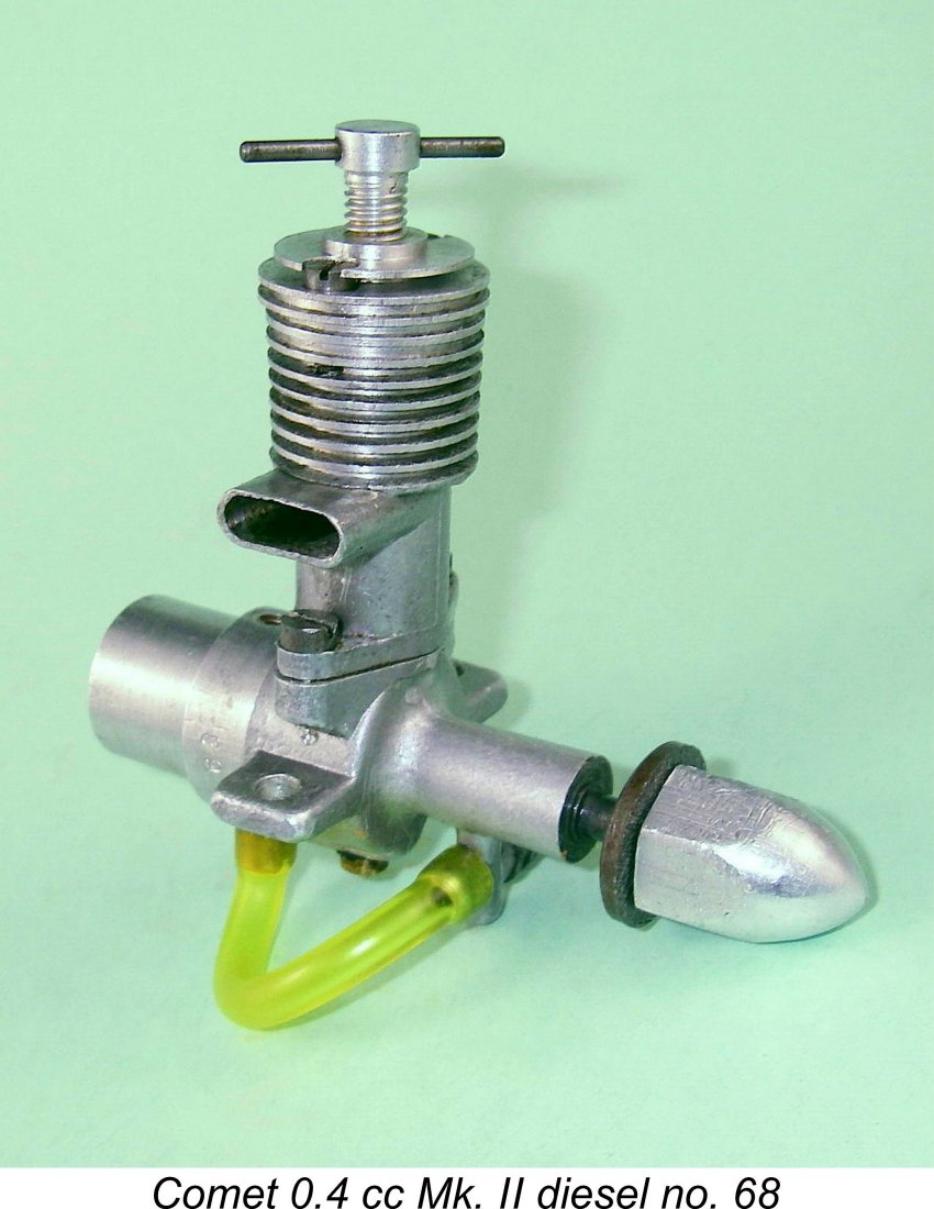
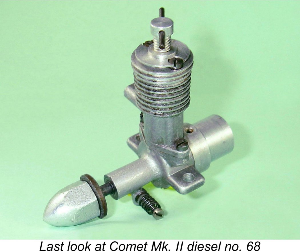
The identity of the actual manufacturer(s) has now apparently been lost forever in the mists of time. In an article on the Comet which appeared in the December 1993 issue of "Aeromodeller", the late O.F.W. "Peter" Fisher noted an unsubstatiated suggestion by the late Harry Hundleby that the Comet may have been designed by future FROG engine designer George Fletcher. However, Harry admitted that he wasn't certain about this. If any reader can enlighten me further, please do so - all contributions gratefully acknowledged! The Comet sold for the remarkably low price (for the period) of only £2 15s 0d (£2.75). According to Fisher, both Mk. I and Mk. II versions were offered. There is certainly some persuasive evidence which appears to support this statement. The primary evidence is the illustration of the unit in the Gamages adverts and on the box labels. The engine pictured in both contexts is specifically identified as the Comet 0.4 cc Mk. I diesel. However, it differs from illustrated engine number 68 in my own possession as well as engine number 133 seen recently on eBay and those pictured by both Fisher and Mike Clanford (see below). Fisher's example bore the number 146 both on the engine and on its box. Miles Patience’s engine no. 56 is similar to all of these examples.
Although there is no absolute proof, it appears logical to assume that the engine shown in the ads and on the box was the Mk. I version, while my own illustrated unit and the other cited examples are Mk. II's. If this is the case, the Mk. I version illustrated in the ads didn't last long - I've never seen one, and my own engine bearing the relatively low number 68 is of the presumed Mk. II type, as is engine no. 56 in the possession of my good mate Miles Patience. I would hazard a guess (and I must emphasize that it is no more than a guess) that experience with the first few dozen examples sent out into service showed the original main bearing configuration to be overly vulnerable to crash damage. The obvious and easy fix was the omission of the machining fore and aft of the "strap" at the intake location, thus increasing the thickness of the main bearing housing and eliminating the stress-raising sharp corner at the point when it joined the crankcase. Presumably the hexagonal alloy prop driver was also found wanting, hence being replaced with the very sturdy steel item seen in the images. There may also have been some internal changes, perhaps explaining the apparent reduction in weight.
The engines were supplied in a sturdy cardboard box with a label showing an illustration of the Mk. I engine (which was a different image from that used in the Gamages advertising) Following the original publication of this article on MEN in 2012, I was delighted to hear from reader and well-known collector Sten Persson of Sweden, who advised that he owned engine number 50 of this series. More importantly, this unit retained both its box and its instruction leaflet! Sten was kind enough to send along a scan of the leaflet, which is reproduced here. Somewhat oddly, neither the box nor the instruction sheet bore any reference to Gamages. Unfortunately, the leaflet is less informative than I had hoped in that it provides no information regarding the actual maker(s) of the engine. It does however confirm that the engine was made in England, a matter which has occasionally been queried. It also includes an interesting recommended fuel mix of 50% ether, 40% Castrol XL (SAE 30) mineral-based oil and only 10% kerosene. Sounds more like a fixed-compression fuel than anything else - I bet that my Drone diesels would run just fine on this brew!! The claim is included that the engine would turn a 7 in. dia. airscrew of unspecified pitch at 6,000 rpm. My sincere thanks to Sten for sharing this interesting piece of model engine history with us. The Comet 0.4 cc Diesel in the Literature As far as I’m presently aware, the Comet 0.4 cc diesel was never the subject of commentary in the contemporary modelling media. The sole contemporary reference to the engine that I've been able to uncover appears in the table of British motors in Ron Warring's early 1949 book "Miniature Aero Motors". The engine was listed in that table (probably compiled in late 1948) as being still in production or at least on sale. No design or structural details were provided, nor were any dimensions included. This presumably indicates that Warring had not had an opportunity to examine an example at first hand. Perhaps a little strangely in view of the above reference, the Comet was not included in Warring's later table of model diesel engines for 1948/51 which appeared in “Model Aircraft” magazine in 1951. Warring's omission of the Comet from this table was most likely due to a not-unjustified opinion on his part that the engine had made an insufficient impact upon the market to warrant inclusion. The engine naturally failed to make an appearance in the 1947 first edition of Col. C. E. Bowden's classic book “Diesel Model Engines“, since it had yet to appear at that time. It was also omitted from Col. Bowden's 1951 third edition, presumably because it had fallen by the wayside in the interim, thus no longer being a relevant inclusion. As a result, it was not until 1977 that further notice was taken of the Comet. The engine was mentioned on page 41 of O.F.W. "Peter" Fisher's interesting albeit often inaccurate “Collector's Guide to Model Aero Engines“, along with the previously-reproduced illustration of an example complete with box. Fisher confined himself to noting correctly that the engine was marketed in 1948 and was produced in very limited quantities in both Mk. I and Mk. II versions. As we’ve seen, this information was almost certainly well founded.
Mike Clanford's useful albeit frequently unreliable 1987 “Pictorial A to Z of Vintage and Classic Model Airplane Engines” included an illustration of the Comet on page 32. The caption added no new information to that already presented above. The example illustrated by Clanford had damaged cylinder fins as well as having the upper cylinder casting installed backwards with the exhaust stack facing left (viewed from the rear of the engine in the normal direction of flight). It also featured a non-original spinner nut. It appeared to have the same kind of modified machine screw needle as that seen on my own illustrated example. As mentioned earlier, "Peter" Fisher contributed a brief article on the Comet to the December 1993 issue of "Aeromodeller" magazine. However, Fisher was unable to add anything significant to the Comet story as presented in this article. Finally, Ted Sladden included a single image of a Comet with its box in his 2014 book entitled "British Model Aero Engines 1946-2011". However, he added nothing to the information summarized earlier. The above account summarizes all of the media references to the Comet that I've been able to find. Not much of a legacy! As a result, I’m forced to rely upon the evidence of a few contemporary advertisements as well as an examination of the engine itself to gather any additional facts. Let's begin by seeing what can be gleaned from the advertisements. Production History
The announcement of the Comet took the form of an insert in Gamages' typical "cut and paste" style of advertising placement. The illustration of the engine showed the Mk. I features described earlier, while the associated write-up extolled the virtues of the design, describing it as "a new engine at a new price" and claiming it to be suitable for models of up to 36 in. wingspan and 6 ounces all-up weight. The engine was claimed to be "the result of months of careful design and test". The rather proprietary style of this advertisement is entirely consistent with the notion that Gamages may have had some level of direct involvement in the engine's inception, although it falls well short of constituting proof. The Comet made a few more advertising appearances thereafter, including the previously-mentioned July 1948 listing in the Henry J. Nicholls "Aeromodeller" advertisement for that month. The last listing that I can find was a one-line mention in Gamages’ October 1948 placement in the same magazine. It appears from this that the engine was not much of a sales success, being withdrawn quite quickly in consequence. Production appears to have been confined to the period April to October 1948.
All that we can legitimately deduce from this is that perhaps some 150 examples were made in total. The number could of course have been higher, although the extreme present-day rarity of the engine makes it appear unlikely that the total produced was significantly greater. Although there must surely be more out there, a determined search has so far confirmed the existence of only eight distinct surviving examples worldwide, including my own as well as the units illustrated by Fisher, Clanford and Sladden. If anyone out there can add to the tally or has any additional serial numbers to share, please let's hear from you! All contributions gratefully and openly acknowledged.................. Having established credible estimates for production figures and dates, let's now see what can be learned by taking a look at an actual example of the Comet. Description In presenting the following description, I must record a debt of thanks to my good English mate Miles Patience. Miles was kind enough to partially dismantle his example of the Mk. II Comet, engine no. 56, to reveal some details of its internal structure. Thanks, mate!
The stroke/bore ratio of 1.44:1 resulting from the above figures is unusually high, even by the standards of 1948. In my experience, only the Kalper 0.32 cc, the Foursome 1.2 cc and the Ace 0.5 cc models exceeded this figure. This ratio explains the very "tall and skinny" appearance of the engine by comparison with later models of similar displacement.
The Comet is built around a lower casting which incorporates the crankcase, main bearing housing, intake venturi, needle valve housing and fuel supply nipple in a single component. A separate casting incorporates the upper cylinder jacket, turned cooling fins, bypass "bulge" and exhaust stack in a single unit. The two castings are secured to each other with a pair of 8 BA machine screws. Both components appear to have been produced by gravity casting using permanent moulds, implying that the intention was to go for a significantly larger production volume than was actually achieved. The cylinder head is a separate component which is turned from aluminium alloy bar stock. It is secured to the cylinder casting The engine is of the cross-flow loop scavenged type. Three drilled holes in the liner serve as exhaust ports, with two more drilled holes directly opposite to act as transfer ports. The latter are fed by a bypass passage formed in a "bulge" incorporated into the upper cylinder jacket casting. Miles Patience’s accompanying image at the left should make this arrangement clear.
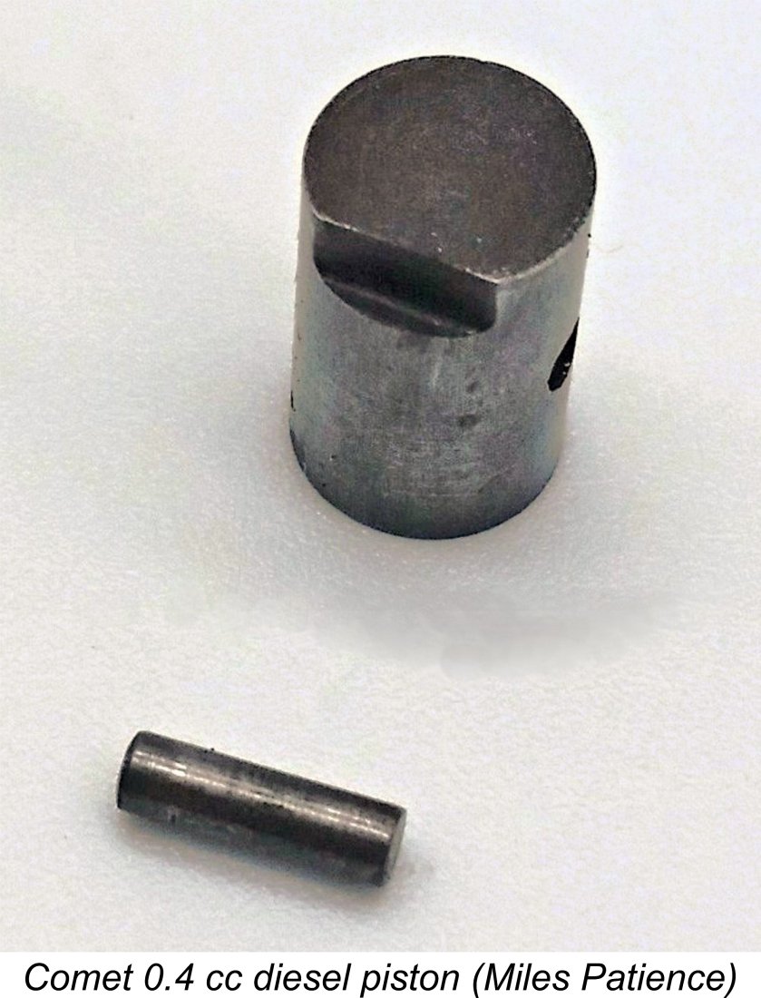
The underside of the crankcase is provided with a drain hole which is tapped 8 BA and sealed with a brass screw and fibre washer. This was a not-uncommon feature of early diesels, being intended to aid in clearing a flooded crankcase. The cast iron piston drives the crankshaft through a long steel conrod of seemingly rather minimal Presumably the makers felt that with this small an engine there would be sufficient friction within the system to secure the prop adequately in normal operation, with an allowance for slippage in the event of a crash or a hydraulic lock to minimize the chance of internal damage. The same system was in fact employed somewhat problematically in the far larger ETA "5" diesel.
At the rear, the engine features an aluminium alloy fuel tank which doubles as a screw-in backplate. The tank is turned and bored from bar stock and sealed at its open rear end by an end-plate which is neatly swaged in place. A brass fuel nipple screws into either of two tapped 8 BA holes at top and bottom of the tank, with a fibre washer being used to ensure a seal. These holes were presumably drilled and tapped after being marked during a test assembly. The nipple can of course be screwed into either hole, thus facilitating either upright or inverted mounting. In either case, the open hole serves as the fuel filler and vent. The hole size is such that a syringe is required for filling the tank. Overall, the quality of the engine's construction is very good indeed. All fits are superb, with no trace of play anywhere in the system and an excellent compression seal with no trace of binding. Indeed, I would objectively say that the standard of fitting is well up to accepted "model engineering" standards. The Comet 0.4 cc Diesel on Test The Gamages advertisements for the Comet claimed that it would turn a 7x5 prop at 6,000 rpm. Interestingly, the manufacturer’s own claim confined itself to citing a speed of 6,000 rpm using a 7 in. dia. airscrew of unspecified pitch. Regardless, this would be a reasonably sprightly performance by the standards of the day for such a small engine. Accordingly, this claim certainly warrants testing! So out to the area under the sundeck behind our house went your intrepid tester, armed with the Comet, a suitable test stand, some fresh fuel and a selection of potentially compatible airscrews. I wasn't expecting this engine to be up to much in the noise stakes, hence my decision to do the testing at home. I was also planning to do only the minimum amount of running necessary to get a feel for the engine's performance - no sense in beating up on an engine of this rarity!
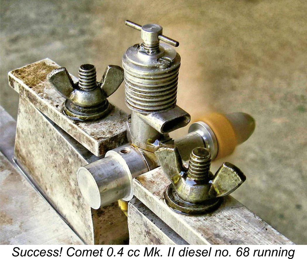
I began the testing with a 7x4 wood prop fitted. It doesn't take much excess fuel at all to flood these small engines, for which reason I set the needle lean and the compression very low at first, my main fear being that a hydraulic lock might develop and cause internal damage. With these old and very rare engines, it's always best to start low and work up by small increments. As it turned out, the potential for a hydraulic lock proved to be the least of my worries! I soon discovered that the prop driver system noted above (no splines, no taper) was problematic in the extreme. The engine fired immediately, but the slightest resistance due to pre-ignition or excess fuel in the cylinder caused the prop to slip and require re-tightening. It's very hard to avoid getting such a small engine a bit wet, especially when unsure of the correct needle and compression settings. Consequently, I never managed to achieve a start - the constant slippage eventually caused me to give up in frustration due to concerns over possible thread wear with the constant re-tightening and excessive tightness required. To get around this issue and allow the testing to proceed, I made up a replacement prop driver of light alloy with a split collet fitting. This completely solved the problem. Prop slippage proved to be a thing of the past, allowing the test to resume with no difficulties. This experience highlighted the fact that the method of prop attachment was perhaps the Comet's major Achilles Heel. Many owners would have given up in frustration when faced with problems such as those which I encountered. This in turn may have led to sales resistance as word got about that the Comet was a problem child in this respect. It may also have led to many of the engines being discarded early on by their frustrated owners. It would have been both easy and logical to incorporate a self-releasing taper in the shaft design, with a corresponding taper at the rear of the prop driver. Why this wasn't done is one of those mysteries which these early model engines constantly throw at us! Following the fitting of the revised prop driver, I re-mounted the little Comet in the test stand and got down to business. It's very hard to choke this engine due to its very small size coupled with the updraft intake, so a small "dry" prime (exhaust port closed) proved more or less essential for starting. As noted earlier, it's extremely difficult to avoid getting this small engine too wet to begin with - either there's no fuel in the cylinder or there's too much! So compression had to be well backed off to achieve an initial start. Once this was done, however, the little Comet proved to be a very easy starter, firing immediately and picking up nicely as one screwed the compression down while the prime ran off.
The compression control was delightfully smooth and responsive as well, making the establishment of the best setting very straightforward. The engine held its compression settings perfectly with no tendency to run back. When starting from cold, the compression had to be raised a little above the best running setting to warm up the cylinder, after which it could be reduced to the optimum setting. Once this was done, the engine ran each tank out cleanly. The tank proved to have more than ample capacity. In fact, the engine ran for over three minutes on a full tank with the 7x4 Top Flite wood prop which I used at the outset. This is of course far longer than required for free flight use. Since no cut-out is provided, one would either have to meter the injection of fuel into the tank or use a separate tank. As expected, noise levels proved to be quite low, although the engine had a very pleasing crisp quality to its sound. So far, everything looked good. However, reality set in when I started taking readings using the various calibrated test props on hand. Despite its truly excellent starting and running qualities, the engine proved to be a rather marginal performer. The results obtained were as follows:
The power absorption coefficients for some of these small props are a bit uncertain, but the figures seem reasonably consistent, suggesting a very modest peak output of around 0.0153 BHP at somewhere around 6,500 rpm. Not an earth-shaking level of performance by any means, but there's certainly enough power there to do an adequate job of flying a small sport free flight model. The figure of 6,100 rpm for the 7x4 Taipan prop undoubtedly lends some credibility to the maker's claim of 6,000 rpm on a 7 in. dia. airscrew. Based upon the above figures, it appears that a fast 7x5 or perhaps a 7x4 prop would have been ideal for flying purposes. It's likely that the very marginal power output combined with the previously-mentioned prop mounting difficulties together explain the Comet's extremely short tenure in the marketplace. While it was basically a very compact, well-made, easy-starting and smooth running unit which sold at a very competitive price and would unquestionably give good service within the limits of its capabilities, it simply lacked what it took to excite the 1948 market. Conclusion
The engine's rarity is also no reason at all to leave its story untold. In making the first-ever serious attempt to document this neat little engine after all this time, I trust that I've created a long-overdue record of a pioneering product of the British model engine industry which would have served its owners well (apart from the prop driver issue!) and hence certainly doesn't deserve to be forgotten. The Comet came and went so fast that it really didn't have a chance to write its own story, as many of its contemporaries managed to do. It's accordingly been down to me to finally give the little Comet its moment in the sun. I sincerely hope that you enjoyed the results! If this article scares a few more examples out of hiding or stirs a few memories which readers are willing to share, no-one will be better pleased than I! __________________________ Article © Adrian C. Duncan, Coquitlam, British Columbia, Canada First published on MEN October 2012 Revised edition published here October 2023
|
||
 Here I’m inviting my readers to share the first-ever in-depth look at another ultra-rare, poorly documented and hence little-known British diesel engine from the early post-WW2 years. I'll be examining the Comet 0.4 cc model which made a very brief market appearance in mid 1948 and then disappeared without trace later in the same year, not to reappear until the onset of the mainstream collector era some decades later, and then only in very small numbers.
 The basic principle of the model diesel (or more correctly, compression ignition) engine originated
  It wasn’t long before a number of commercial interests began to take notice of the efforts of Sparey and his fellow pioneers such as
 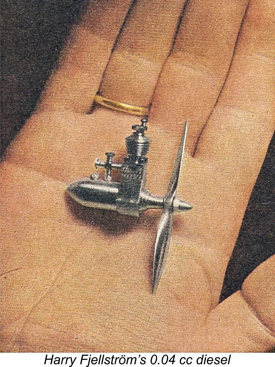 The French took the early lead with the cute little
 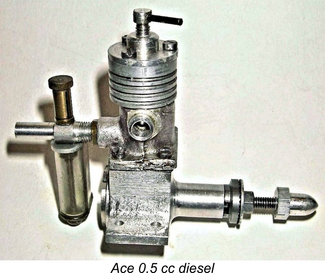 The first British move towards the commercial development of sub-miniature diesels came in mid 1947 with the introduction of the London-made
 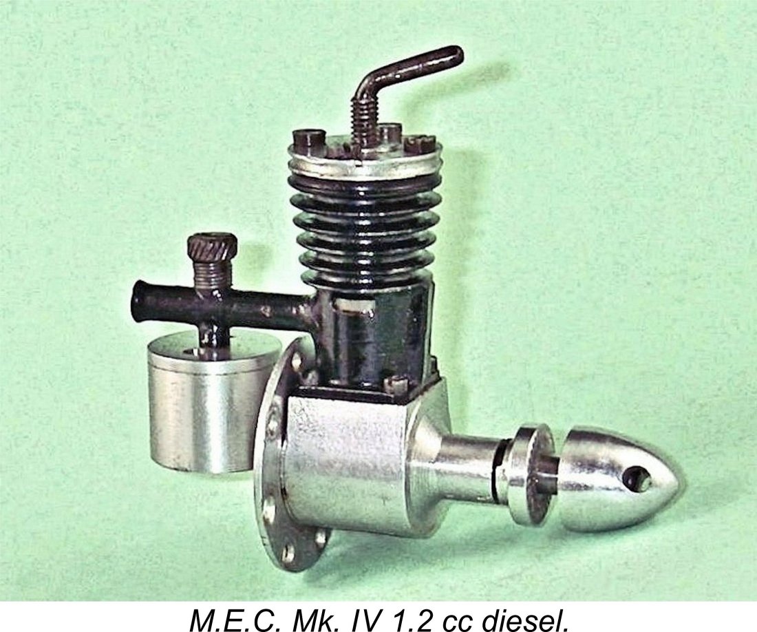 businesses to start thinking about getting into the game with their own "house" model engine designs. The Milford Gauge Company of Harrow had actually initiated this process somewhat earlier by introducing the Mk. I version of their 1.41 cc
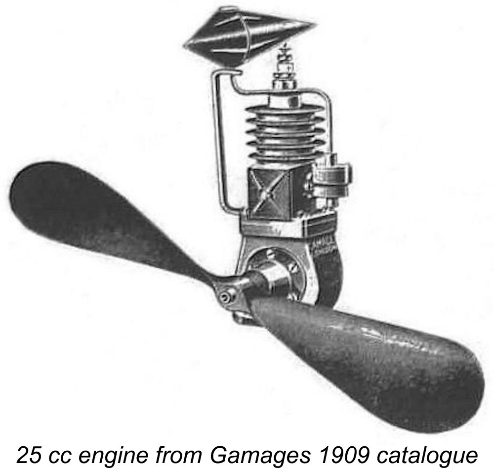
 The advertising record seems to confirm that this engine was predominantly sold through Gamages, making it appear highly likely that it was either commissioned by that company or handled by them on the basis of some kind of distribution agreement. However, the engine's appearance in the Henry J. Nicholls "Aeromodeller" advertisement of July 1948 confirms that Gamages were not the exclusive sales outlet.
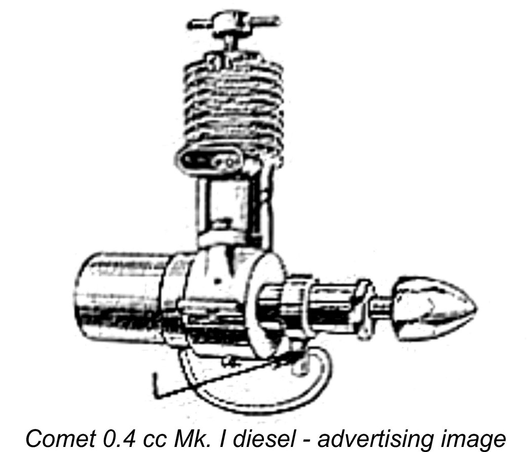
 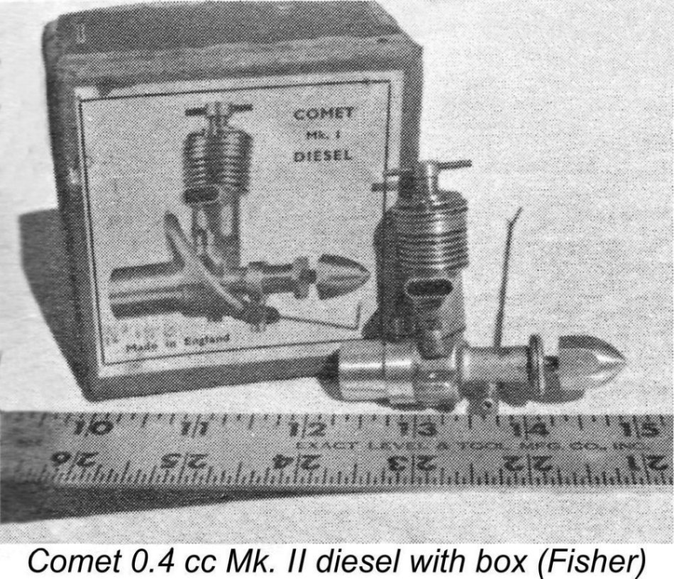 The engine depicted in the adverts and on the box has what appears to be a different tank as well as a hexagonal prop driver apparently machined from the same hexagonal light alloy bar stock used to make the spinner nut. It also features a pronounced "strap" around the main bearing housing at the intake location. This "strap" appears to have been created by machining the housing fore and aft of the intake location, resulting in a substantially smaller-diameter main bearing housing with an extremely vulnerable-looking sharp corner at the junction of the bearing housing with the front of the main crankcase. Worse yet, the housing was completely unbraced. The advertised unit had a claimed weight of 1.7 ounces, substantially more than the measured 1.4 ounces of the actual example on hand for examination.
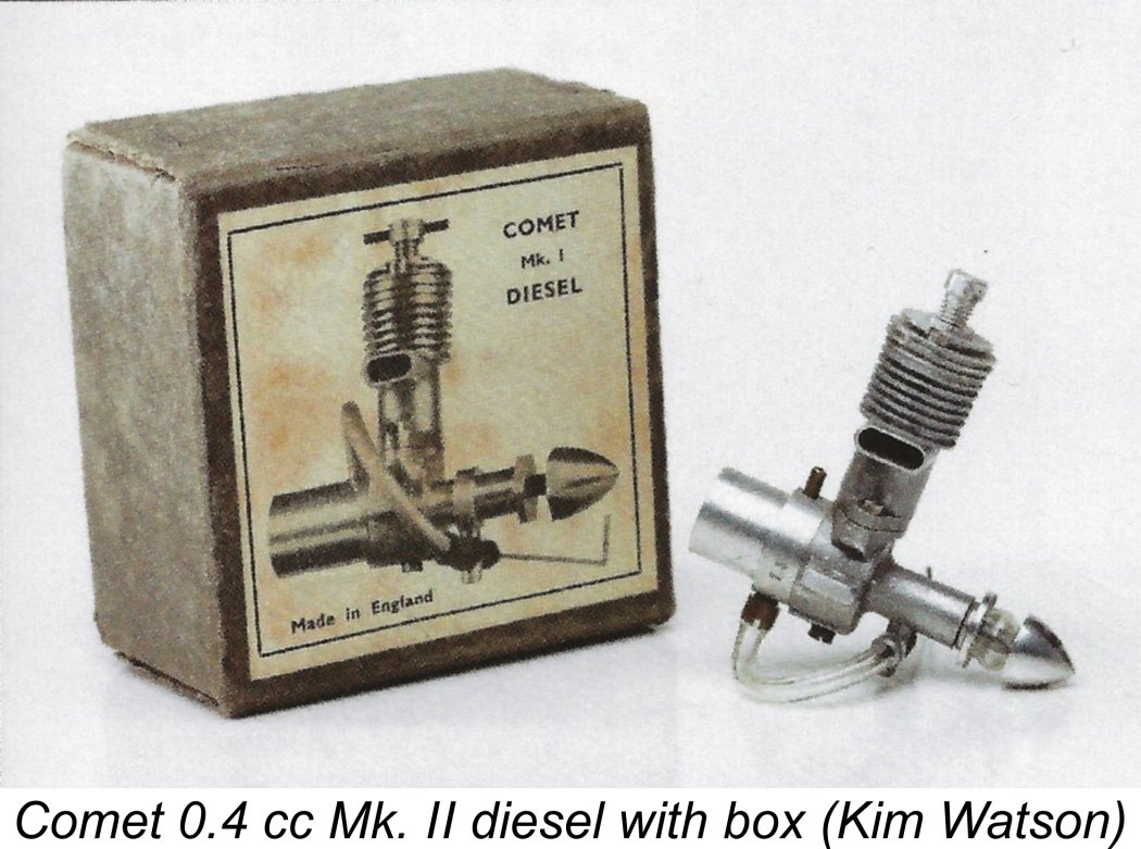 Some may see the continued use of the Mk. I boxes throughout as a fatal objection to the Mk. I/Mk. II hypothesis. For my part, I can’t agree with such a viewpoint. In reality, the very low production figures which are suggested by all the evidence would logically have led the makers to use Mk. I boxes already on hand when packing the Mk. II versions rather than going to the expense of printing a new set of labels for an engine with a highly uncertain sales future. Far from considering this to be a death-blow to the Mk. I/Mk. II hypothesis, I would actually have been surprised to see the Mk. II version being re-packaged under these circumstances.
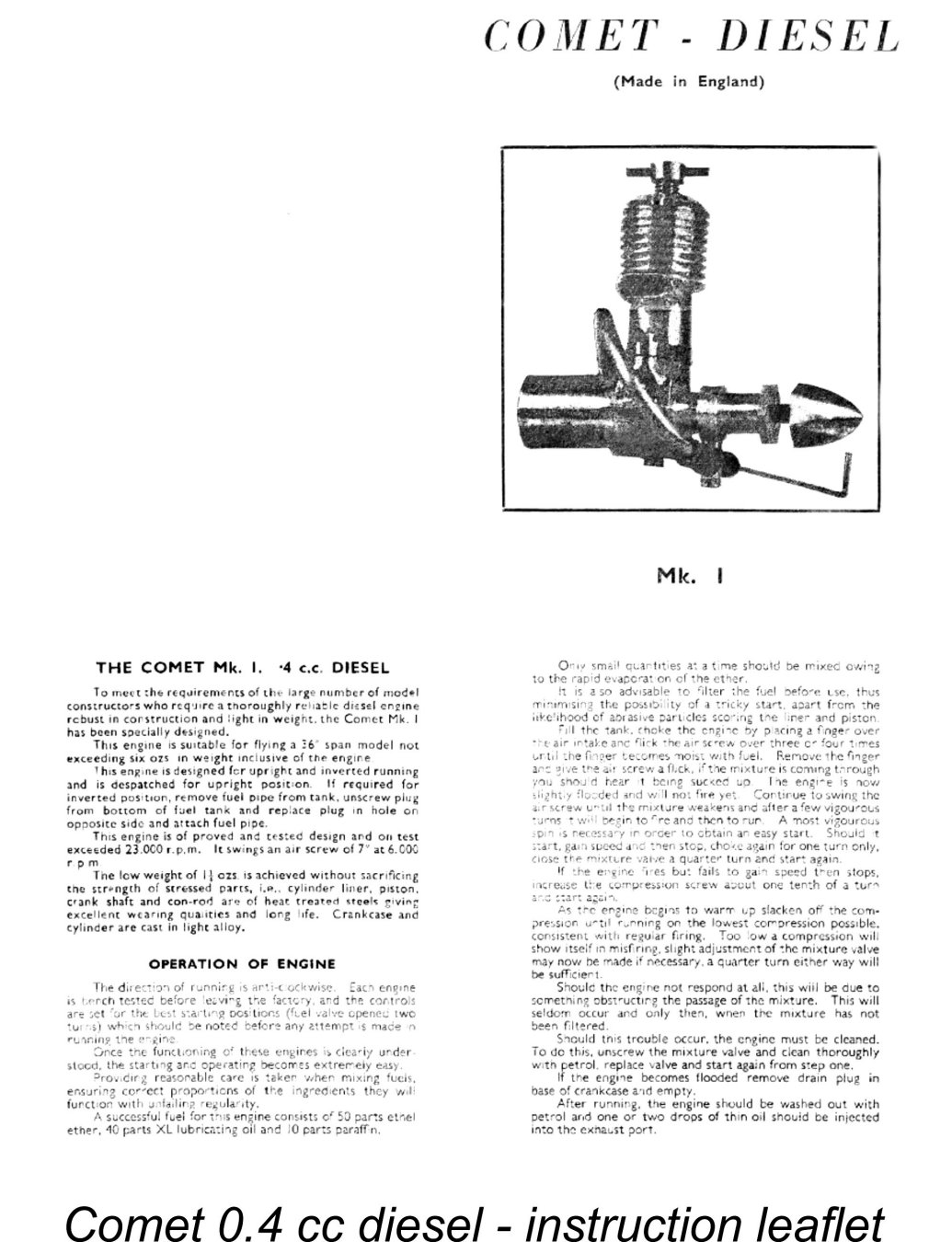 together with the serial number hand-written in one corner in most cases. The same number normally appeared stamped onto the tank/backplate unit of the engine itself, although the odd example has been encountered with no serial number on the engine itself - as of September 2012 my good mate Kevin Richards had such an example.
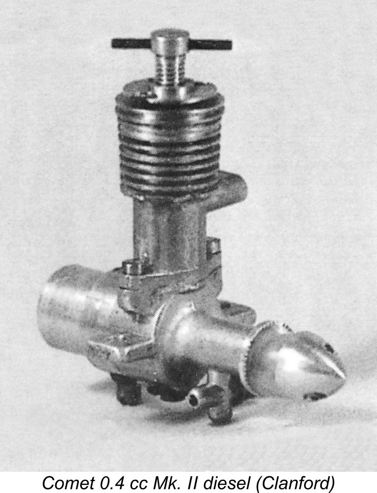 Page 37 of the late
 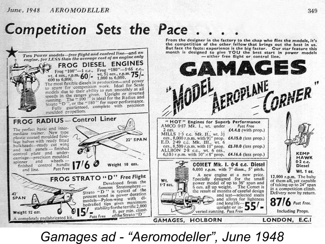 The Comet 0.4 cc Mk. I diesel made its initial public appearance in a Gamages advertisement in the June 1948 issue of “Aeromodeller” magazine. Allowing for editorial lead time (the June issue actually appeared in mid-May), this implies that the engine must have been in existence no later than April 1948.
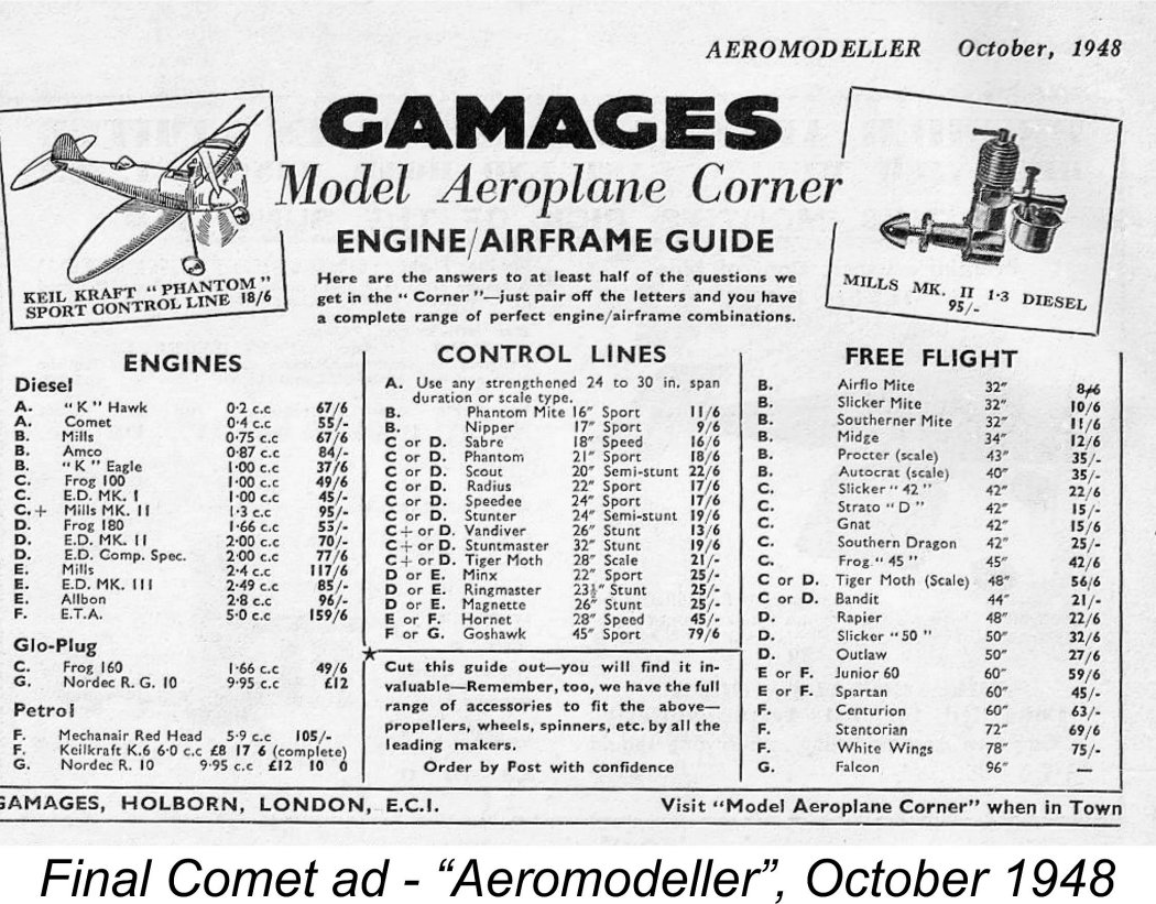 Whatever the facts of the matter (and it's highly unlikely that we'll ever know the full story), there's absolutely no doubt that total production was very small, making the engine extremely elusive today. The only five serial numbers of which I have certain knowledge are Sten Persson’s boxed engine number 50, Miles Patience’s engine no. 56, my own engine number 68, boxed engine number 133 which appeared on eBay some years ago and Fisher's engine number 146. The boxed example illustrated in Ted Sladden's previously-cited book appears to be engine no. 73, but this number is somewhat unclear. All of these are Mk. II variants.
 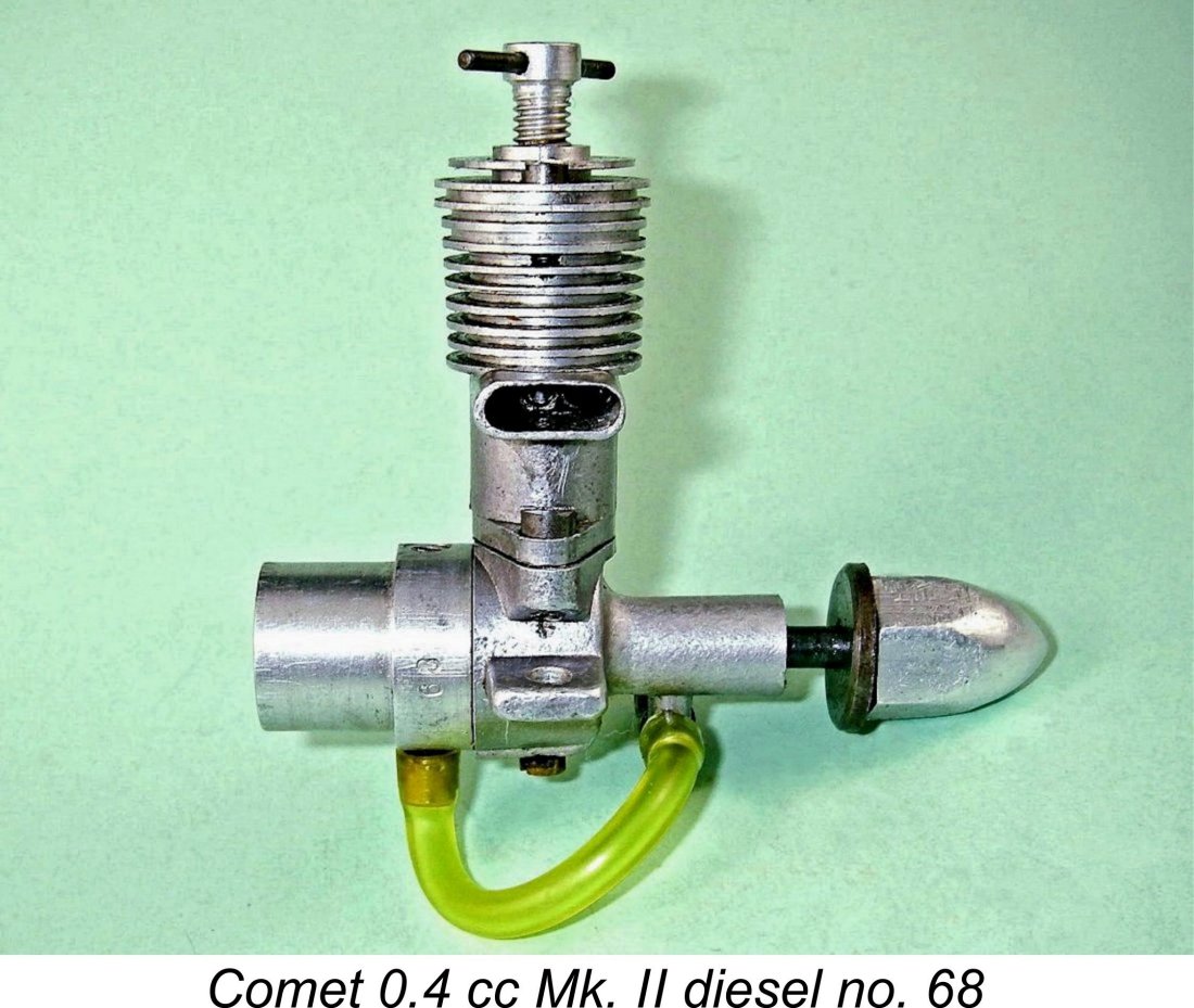 The Comet 0.4 cc diesel is a basically conventional cross-flow loop scavenged long-stroke crankshaft front rotary valve (FRV) compression ignition engine. Although I was unwilling to disturb the excellent seals or risk thread damage on my little-used example of the engine by undertaking a full disassembly, it proved possible to obtain accurate bore and stroke measurements. These yielded figures of 0.281 in. (nominal 9/32 in. - 7.14 mm) and 0.406 in. (nominal 13/32 in. - 10.32 mm) for the bore and stroke respectively for a calculated displacement of 0.025 cuin. (0.413 cc). British designers of the period tended to work with nominal dimensions expressed in fractions of an inch - why beats me given the fact that they always quoted their displacements in cubic centimetres (cc)!!
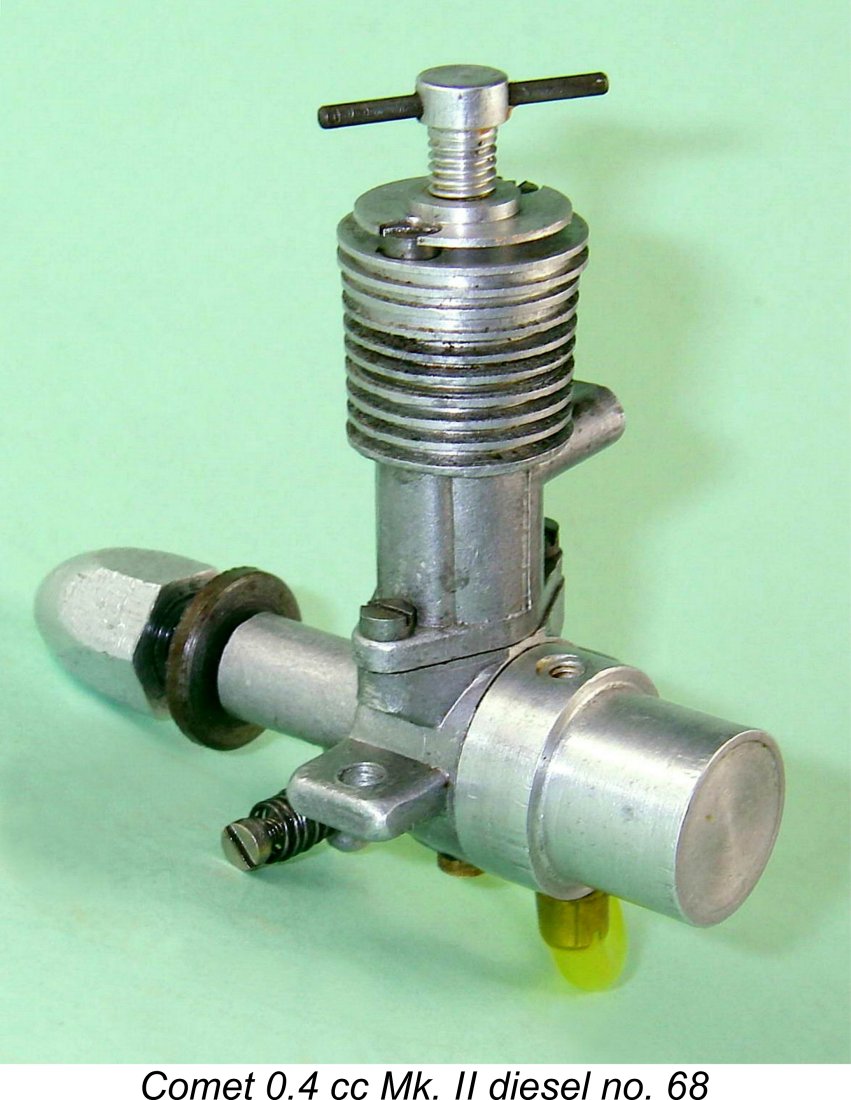
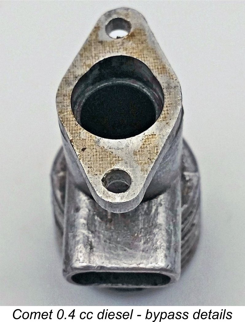
 The transfer openings are located considerably lower down the bore than their exhaust counterparts. The attached image at the right provided by Miles Patience shows that the appropriate port timing is maintained through the inclusion of a step along the lines of the pre-existing
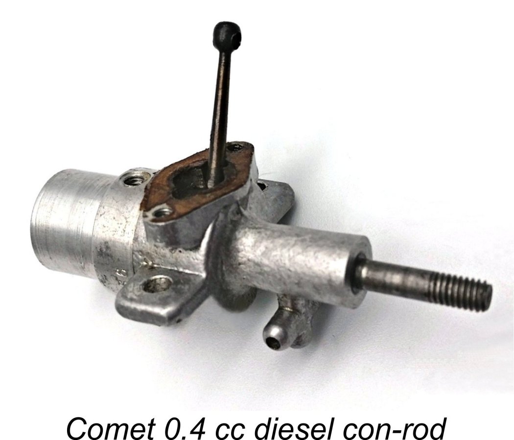
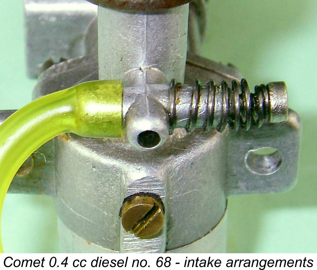 The integrally-cast updraft venturi stack is located beneath the main bearing housing. It incorporates both the needle housing and the fuel nipple. The needle valve is of the surface jet type, with the actual needle being externally threaded 8 BA to match the female thread formed in the needle housing. This type of carburettor is generally considered to give relatively poor suction, but the fact that the intake bore is only 0.078 in. (2 mm) dia. leads one to suspect that suction would not be a problem in this case. All of the engine's air supply has to pass through this very small bore, since no sub-piston induction is incorporated.
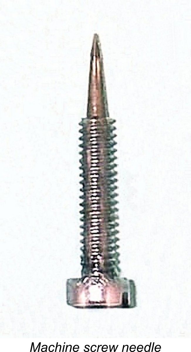 Most of the images of this engine that I've seen previously show it equipped with an absurdly long and highly vulnerable extended wire needle valve control. The illustrated example, which appears little used and completely undisturbed, features a far more practical needle made by adding a taper to the end of an 8 BA slot-head machine screw. The taper is cleanly and accurately formed, leading me to suspect that this is an original component, like the rest of this example. Perhaps it was offered as an alternative. The unit illustrated by Clanford evidently featured a similar needle. This design is certainly far more practical in terms of crash resistance, although a small screwdriver is required for manipulation. Tension is very effectively provided by a coil spring.
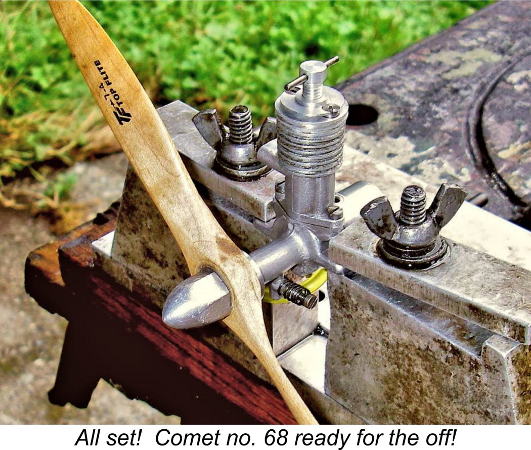
 Once running, the Comet proved to be a very steady performer indeed, holding its note without a trace of a misfire and maintaining a very steady speed on a given prop. The needle was a bit on the sensitive side, with the optimum setting being a touch critical, but response to the needle was sufficiently positive that the ideal setting could be found with little trouble by making very small adjustments (using a small screwdriver), pausing in between adjustments to assess results. The really good news was that once the setting had been found, the engine would re-start easily hot or cold without the need for any further needle adjustment. The spring tensioning arrangement was completely effective in maintaining a given setting during operation. One turn of the needle was found to be the perfect setting for most props tried.
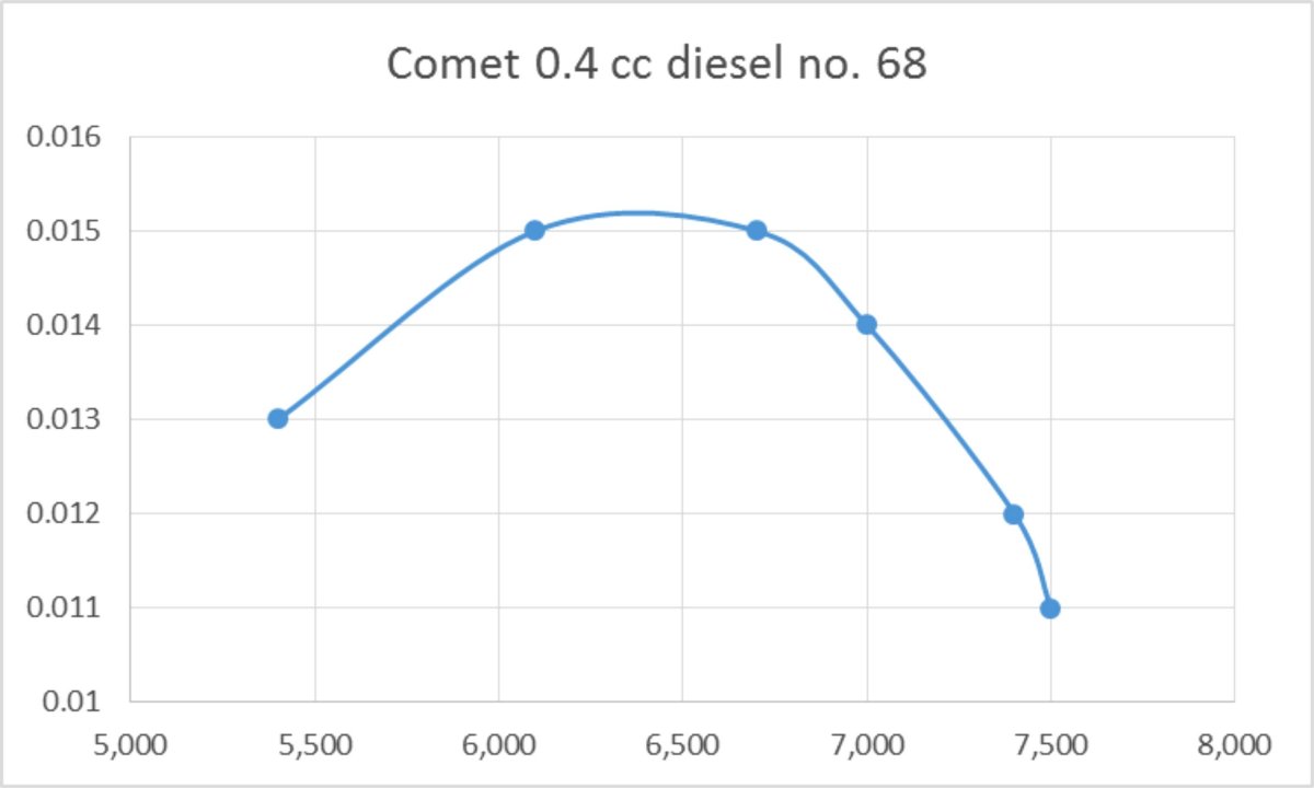
 The Comet 0.4 cc diesel is so rarely encountered these days that I'm forced to admit that any interest which it possesses is mainly academic - few of us will ever enjoy the privilege of owning one. However, that's no reason to stop looking - hopefully a few more examples will fall out of the attics where they've been hiding all these years! After all, at least 150 of them once existed - a reasonable percentage of those should surely have survived.
| |