
|
|
Danish Delicacies - the Viking Range
It was my personal curiosity about the Viking engines that got this project started. Once my interest had been aroused, I realized right away that in order to do justice to the topic I would need help from some knowledgeable individual(s) in Denmark. Immediately I thought of Danish team-race expert and multi World Championship engine builder/tuner Luis Petersen, who has become a good friend and valued colleague over the years. I have published Luis’s work before in the form of his most interesting 1977 comparative test of a number of then-current (and now classic) team race diesels of the mid 1970’s. Recalling this article, I had little doubt that Luis would be the right guy to help out with the Viking project. When I first contacted Luis in early 2016 to see if he could assist me in the preparation of an article for this website covering the Viking engines, his initial response was to send me a copy of his own earlier Viking article which had originally appeared all of 26 years previously in a 1990 issue of the Danish modelling magazine “Modelflyvenyt” (issue 1990-1). Naturally, the original article was in Danish, a language with which I have no familiarity. However, Luis very kindly agreed to assist by providing a translation of the earlier article for my reference and editing. It’s hard for me to find the words to express my gratitude.
In addition, my good friend Lars Gustafsson from Sweden also got in on the act by providing scans of a number of Swedish advertisements for Danish engines, complete with English translations. This did much to inform my research into the penetration of Danish model engine ranges to other Scandinavian markets. Thanks, Lars!! All of this information was far too interesting to go unused, since it added a great deal of historical context to the Viking story. Consequently, I elected to create a completely new article which combined Luis’s original 1990 Viking material with the additional information that he, Jens and Lars subsequently provided on other Danish model engine ranges from the pioneering era. The resulting article on Danish model engine manufacturers may be found elsewhere on this website. The Viking range was the last Danish model engine series to emerge, doing so in early 1950. By that time the earlier Diesella, Deofok and Mikro diesels were history, but the Thorning and CEROS models as well as the Greig engine kits were still in circulation. This was the domestic competition that the Viking range had to face. Details of these engines appear elsewhere on this site.
In support of this effort, Luis published a brief note in the Danish modelling magazine "Modelflyvenyt" in which he requested that anyone having an example of the very rare Viking 3.2 cc diesel model get in touch. The amazingly productive results of this inquiry were summarized in a subsequent article by Luis which appeared in the pages of "Modelflyvenyt" in 1990, the year in which the Viking range turned 40 years old. To summarize what was learned as a result of Luis's original inquiry, I can do no better than turn the pen over to him at this point. What follows is my edited, updated and slightly reorganized rendition of Luis’s own translated words on the subject. The Viking Range Turns 40 Years Old! By Luis Petersen Some years ago, in an issue of the magazine “Modelflyvenyt”, I placed a small note with a request that anyone having a 3.2 cc Viking diesel should contact me. I've never received so many inquiries in such a short time, despite the fact that some of my other articles were far more interesting in my own opinion! Several people explained that I had probably made a mistake and called for a 3.2 cc Viking glow-plug motor. Others asked whether an engine that they had in their possession was one of these models. Fortunately, one reader called who knew this engine well. He told me that in 1950 he had purchased just such an engine as new from the Hobby Shop (that's the name of the store) at 175 Vesterbrogade in Frederiksberg, near Copenhagen. He still had the engine and was happy to lend it to me for measurement and photography for the magazine. There was also an individual who had chanced to read that issue of “Modelflyvenyt” with his brother after Christmas dinner. This came about entirely fortuitously because that issue of the magazine had been an Almond Gift. (Editor's note - In Denmark on Jule Eve (Christmas Eve), Danish families share an elaborate dinner in which a rice pudding dish is the featured dessert. One of the dessert servings has an almond concealed in it. The finder of that almond is entitled to a small additional gift. The magazine was that gift in this instance - A.D.). Solely through this lucky chance, this particular reader was made aware of my interest in the Viking engines. In view of the great ongoing interest in these engines that had been found to exist, the Comet Model Flying Club of which I am a member began to consider creating an Oldtimer competition class for these old engines, to be flown both at our home Amanger Field (2 km. from Copenhagen town centre) and elsewhere. The decision was eventually taken to adopt the British Weatherman class, merely substituting the Viking 2.5 cc diesel for the British Mills 1.3 model. Coincidentally with the appearance of the present article in May 2016, we were preparing to hold our first contest under these rules. I plan to provide pictures of the finished models and the contest results to be added to this article in due course.
Fair enough, but how did it all begin?? Well, Tommerup Clausen had a factory at Lundbyvej in the northern part of the south-central Danish island of Fyn, on which the city of Odense is also located. The facilities were housed in a former nursery! The workshop equipment included lathes, milling machines, grinding equipment and honing machines. Using this equipment, Clausen manufactured an amazingly diverse range of products, including complete gramophones, tools, window fittings and parts for vacuum cleaners and milking machines. However, his most famous products were probably the Viking model engines, which were produced from 1950 to the late nineteen-sixties. The staff consisted of a foreman, a few journeymen and a succession of apprentices and boys. I was lucky enough to establish contact with a few of the former apprentices, and the following is a synthesis of their recollections along with information extracted from various media articles from that time.
The crankshafts were turned from the material of an old automotive half-shaft, then nitride-hardened in a cyanide bath. The use of old half-shafts was in fact very common at this time – a number of early British manufacturers are known to have obtained their crankshaft steel from a similar source. The crankcases were cast after discussions with the Kramer foundry, who made the early castings. Clausen later established his own foundry to make crankcases and other cast components. Cylinder sets were machined, honed, measured, sorted and then lapped to a final fit with Brasso. The latter step was one of the earliest apprentice duties. Clausen also ensured that all engines were test-run prior to dispatch. Every Thursday, he delivered the weekly production of an average of 25 units to the sales agency for the Viking range. This was DMI (Dansk Modelflyv Industri or Danish Modelaero Industries) of Brogade 6-8 in Odense, which by then was owned by Svend Schou. The original selling price was 27 kr., and this transaction provided Clausen with the wages for the week, which were due on the following day - Friday! During testing of the engines, a form of vibration tachometer was used. This consisted of a rod having a Eventually one of the apprentices learned to pick the “good” engines. He was a model car enthusiast, and he installed a good 'un in a small shaft-drive car of a type known in Scandinavian model car racing circles as a "Toad" (a generic term used in the Scandinavian countries to denote an American-style "teardrop" tether car - in Swedish for example, "padda" - A.D.) He used this vehicle to set a course record at an Odense model car club meeting. Unfortunately for him, when the other club members learned where he was working, his performance was nullified on the grounds that he was a “professional”!! A total of 5 Viking models were manufactured over the 19 years during which production continued. The final total produced was reportedly some 25,000 engines of all types combined. OK, Adrian here again! Our very sincere thanks to Luis for providing the information set out above. It’s now time for Luis and I to combine our efforts once more by presenting some basic information about each of the Viking model engines produced by Christian Tommerup Clausen. We'll deal with the various models in the order in which they appeared on the market. Viking 2.5 diesel – 1950 – 1969
The initial retail price was 27 kr., which was clearly an artificially low figure intended to stimulate initial interest and get a few examples out into the field. It was soon increased to a more economically-rational 54 kr. By the time of publication of the 1968 catalog from DMI, the stated cost was 87 kr. A brief earlier article about this engine appeared some years ago on the late Ron Chernich’s invaluable “Model Engine News” (MEN) web-site. That article may still be accessed through this link. Considering its introductory date, it’s a remarkable fact that a total of some 20,000 examples of this retrospective sideport design ended up being produced over its almost twenty-year production life. These are impressive statistics for a model engine design which was basically outdated at the outset from a technical perspective. The only parallels that we The reasons for the widespread long-term use of the Viking 2.5 cc diesel by Scandinavian modellers were closely parallel to the reasons for the ongoing use of the E.D. and Mills sideport engines in Britain and elsewhere. The Viking engines were well made, sufficiently robust, easy starting, dependable, reasonably priced and well marketed, so that owners could easily get spare parts from all Danish hobby shops. Even as late as 1979, some ten years after the final withdrawal of the Viking 2.5 cc model, it remained possible to find new spare parts in certain Danish model stores. The Viking 2.5 cc diesel was an exaggeratedly long-stroke unit featuring bore and stroke measurements of 12.72 mm and 19.50 mm respectively for a displacement of 2.48 cc. These figures were actually borrowed from the earlier Thorning III model (which remained in production at the time when the Viking 2.5 first appeared). The engine weighed a quite reasonable 145 gm (5.12 ounces) complete with tank. Claimed output was 0.15 BHP @ 6,000 rpm. This was very definitely a low-revving long-stroke unit whose strong suit was the development of high torque at low speeds.
However, in the case of those two models the motivation was almost certainly to facilitate the effective use of dual bypass/transfer ports, one on each side. The use of sideport rear induction pretty much mandated the use of a single front exhaust if twin opposed transfers having reasonable timing were to be employed. The detail and workmanship displayed in the Viking 2.5 were first class. The way in which the lower fins were flared into the inlet boss at the rear is particularly noteworthy. Cutting those fins in this configuration required that they be formed with a slitting saw (or possibly a gang of them) while the crankcase was rotated around the bore axis between very precise limits. Quite a challenging manufacturing step, and one which most manufacturers would probably have sidestepped for cost reasons. That said, it does result in a very attractive appearance. The fuel tank of coloured plastic (blue initially, later red) is also very eye-catching. Further attention to detail may be seen in the design of the needle valve assembly. All versions of the engine used an externally-threaded steel needle. Prior to the summer of 1953 the engines featured a neat but fragile screw-in cast carburettor body which incorporated both the tank top and an internally-threaded It appears that experience in the field soon demonstrated that the cast carburettor was unacceptably prone to breakage from one cause or another. It was evidently for this reason that the cast carburettor was supplanted in the summer of 1953 by the far more sturdy and sophisticated set-up seen in the attached photographic images. The induction venturi tube was now turned from aluminium barstock while the tank top was now a separate soft aluminium stamping. The "spraybar" was now a two-piece screw-in set-up featuring a surface jet on one side and a needle carrier on the other. The screw-in surface jet did double duty by securing the stamped tank top in position. The little locking thimble on top of the needle carrier made for an excellent air-proof joint as well as ensuring the stability of the needle setting. This "gland nut" feature was similar to the designs seen on contemporary high-performance engines like the Dooling, ETA, Nordec, Super Tigre and older McCoy models. The rather thin drop-in Meehanite cylinder liner was retained in the upper cylinder jacket by an externally threaded brass plug that engaged with an internally threaded recess at the top of the cylinder casting. The G/A cut-away section reproduced above should make this clear. The hardened nickel-chrome steel piston had an exaggeratedly-long skirt, which was thought necessary in the early days to ensure adequate compression seal. A number of other early designs such as the original FROG models from England also exhibited this feature.
Another legitimate criticism is the somewhat insubstantial construction of the cylinder liner. As noted earlier, this is made with very thin walls. Moreover, it is split at the sides at exhaust port level to create the two lengthy bypass passages. This makes the lower cylinder extremely prone to "pinching" when it is installed in the crankcase. The fact that the bore has almost no taper doesn't help - many of these engines are encountered with pinched pistons around bottom dead centre. Luis noted that this is a well-recognized trait of these engines, and one which gives rise to the need for great care in re-assembly. It's essential that any high spots be relieved so that the liner is no more than a smooth light push fit all the way down. It's also vital that scrupulous cleanliness be maintained during re-assembly. The above issue is somewhat exacerbated by the fact that the cylinder liner is subject to hold-down stresses throughout its full length. In consequence, the two halves of the lower cylinder are somewhat prone to distortion though microscopic buckling. The Thorning III with its identical cylinder design got around this by incorporating a location flange just above exhaust port level which bore upon the top of the crankcase casting. The cylinder was retained by a "dog collar" which acted against this hold-down flange, thus relieving the actual cylinder liner of any hold-down stresses whatsoever. It has to be said that in mechanical terms the Thorning design was greatly superior, if far less elegant in terms of appearance. The centre of the very substantial compression screw is drilled out. The weight saving resulting from this additional manufacturing step is negligible, making it appear likely that the motivation was actually to eliminate any chance of point contact between the screw and the top of the contra piston. This configuration has been shown to significantly reduce the tendency of compression screws to unwind under operating conditions. It’s a modification that I have frequently and successfully applied to my own “flying” engines.
We already noted the summer 1953 switch from a cast carburettor body to a composite affair utilizing a stamped tank top. The first engines had blue plastic tanks, but from 1954 onwards the tanks were made of red plastic. Apart from these few relatively minor changes, the engine remained unaltered right through to the end of production. At the outset, a production rate of 25 units per week was achieved. However, this must have been increased significantly fairly early on, since by September 1952 it was claimed that a total of some 7,000 examples of the Viking 2.5 cc diesel and its low-production 3.2 cc companion (see below) had been sold. As of January 1st, 1956, production figures for all Viking models was said to be around 12,000 units. By 1959 this total (again for all models) had reached a claimed 15,000 units. Throughout the life of the marque, the 2.5 cc model remained the most enduringly popular member of the Viking family. In all, some 20,000 examples were manufactured prior to the withdrawal of the range in 1969. This represents around 80% of the total number of engines produced for all models. The Viking 2.5 cc Diesel on Test
The writer of the Viking test report praised the engine's handling and overall performance very highly, citing it as the most powerful Danish 2.5 cc engine yet to appear. He found a peak output of 0.132 BHP @ 6,000 RPM, a little less than the manufacturer's claim of 0.15 BHP at the same speed. Having two well-used but still highly servicable and completely original examples of the engine on hand, I felt that I had no excuse for not putting the test stand back to work and conducting an independent evaluation of the manufacturer’s performance claim. I was also curious regarding how my results would compare with those published in "Teknik for Alle". Frankly, I was a bit skeptical going into this test, because that’s a lot of power at such a relatively low speed! If the manufacturer’s claim was anywhere near accurate, the engine was a mega torque producer at low revs. In theory, it should turn an 11x6 APC airscrew at somewhere near its claimed peaking speed of 6,000 RPM. I elected to begin with that prop just to see if theory was borne out in practise. My skepticism was reinforced by Luis's comment that he and his friends used to use SEMO 8x6 plastic airscrews on their Viking 2.5 cc models. Admittedly that prop was a bit of Neither of my examples of the Viking are anything like pristine - they have both clearly seen a lot of use and have led a hard life - note the broken cooling fins! However, they remain in good mechanical condition. The compression in both examples is a bit on the leaky side, but all other fits remain excellent and there's plenty of compression for starting and running. The two engines are both in completely original condition, hence being truly representative test samples. The tanks on both engines are faithful replicas very kindly provided by Luis (thanks, mate!), but that doesn't affect the engines at all in an operational I've had these engines for many years and had run them both a long time ago, but that was way back then .........I welcomed the present opportunity to get reacquainted! I elected to give both engines a chance to show what they could do, because there's always value in duplicating tests with different examples of the same engine. A wise decision, as things turned out........... So without further ado, the first engine to be tested went into the test stand with an APC 11x6 prop installed at the business end. A point to note here is the fact that the undersides of the mounting lugs on these engines are not laterally parallel - they slope upwards towards the outer edges. Accordingly, they don't sit flush on a pair of parallel flat mounting surfaces such as those of a typical test stand. I use shims under the outer edges to spread the load and thus prevent distortion or even cracking of the crankcase. I recommend that others do the same. I used a straight fuel mix of equal parts ether, kerosene and castor oil, which generally works pretty well in these old long-stroke sideport engines. It was a bit of a chore to get the Viking going first time thanks to the years of storage oil that remained in it. However, once I got it well flushed out with fresh diesel fuel it started readily enough.
Once running, the engine was a real pleasure to set thanks to the very fine mixture control afforded by the externally-threaded needle. Compression settings too were non-critical and easily established. The engine ran very smoothly and consistently at all times with no detectable tendency to sag as it warmed up. The one oddity was the way it looked when running - throwing the exhaust gas stream forward right into the prop disc where it was comprehensively dispersed, oil residues and all! No matter where you stood, you got well doused with castor oil spray! Shades of WW1....... The following speeds were recorded on the various props tried:
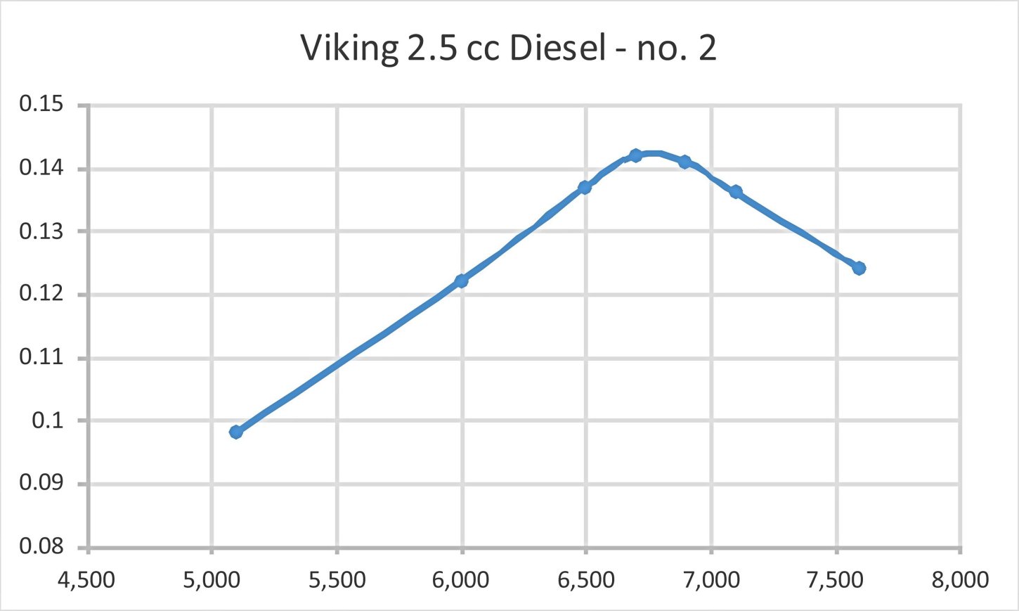
By the time I got to the APC 10x6, vibration levels were becoming pretty noticeable. Because of the vibration issue, I never got close to the 8x6 prop size which Luis Petersen recalled using in former days. In any case, such a prop would have taken the engine way past its peaking speed. This is not an engine to under-prop! The tester for "Teknik for Alle" had said as much way back in 1950, and he was right. The above results generally met my expectations going in. It's worth noting that my pre-test prediction of something close to 6,000 rpm for the APC 11x6 proved to be pretty accurate! The engine peaked as expected at a slightly higher speed than claimed by the manufacturer, but didn't deliver quite the quoted power. I found a peak output for this example of around 0.124 BHP @ 6,500 rpm. Since these figures are generally consistent with the findings of the previously-cited test report in "Teknik for Alle", I was feeling pretty This is actually a pretty respectable performance for a 2.5 cc sideport diesel of basically vintage design. There's no doubt that this engine would do a highly creditable job of flying a sport or scale model - those big props shift a lot of air! A 10x8 would probably be an excellent flying prop for this engine. Moreover, the Viking's user-friendly handling characteristics would greatly add to the enjoyment of using it in the field. No wonder it remained as popular as it did for so long! OK, so much for engine no. 1. Next up was its partner, engine number 2! Ths one proved to be if anything a little "leakier" in the compression department than its companion, and I actually found that my standard remedy for worn engines - an extra prime of straight upper cylinder lubricant - was a great help in starting. Using this approach, it started just as readily as its opposite number. Once going, running qualities too were just as positive. It only took a couple of test runs on different props to confirm that this example was going to surpass the performance of engine no. 1 by a substantial margin. It was well up on all props tested above 6,000 RPM. The results below speak for themselves:
Now that's a bit more like it! The implied peak of around 0.142 BHP @ 6,700 RPM is as close to the manufacturer's claim as you could wish, exceeding the figures reported in "Teknik for Alle" by a healthy margin! Note however that as expected, the peak was found at a slightly higher speed than that cited either by the manufacturer or the "Teknik for Alle" writer. For a 1950 2.5 cc sideport diesel, this really is a pretty impressive performance. Massive amounts of lovely low-end torque on hand, allowing the engine to swing a really meaningful prop to good effect. Combine that with their excellent handling, and these engines undoubtedly deserved their positive reception from the Danish modelling public! Viking 3.2 diesel – 1950-1951?
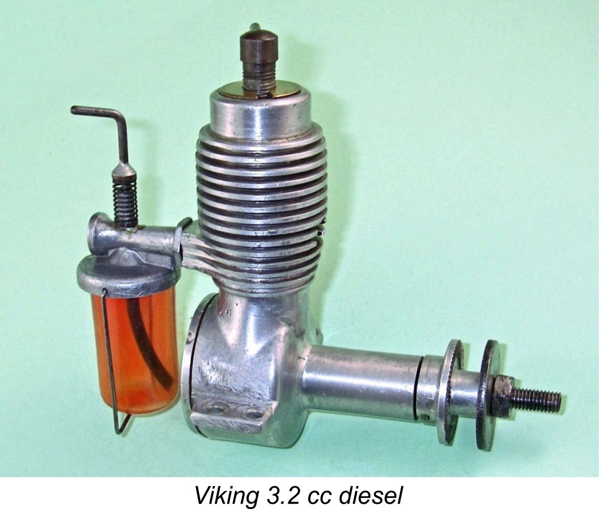
The external appearance of the engine was little changed. The most obvious difference is the larger-diameter unfinned top portion of the cylinder jacket which had to be sized to accomodate the larger-diameter brass disc required to retain the bigger-bore cylinder. The cooling fins are less inwardly tapered at the top to accomodate this feature. The grooves between the fins are also less deeply cut to provide sufficient material for the enlarged installation bore for the cylinder liner. Apart from these relatively subtle differences, it would be very easy to mistake this engine for the more common 2.5 cc model. The illustrated example of this relatively rare engine is a well-used unit which was very kindly made available to me by Luis Petersen. Before sending it to me, Luis took it apart to check the internal geometry. The measured bore and stroke of this example are 14.30 mm and 19.65 mm respectively for a displacement of 3.16 cc. Near enough, allowing for "lathe operator's license"!
One interesting observation is the fact that the manufacturers don't appear to have taken the extra bore fully into account when laying out this design. It would appear that they just assumed that the 2.5 cc crankcase using the same stroke would accommodate the extra bore, hence making no design changes. As a result of this incorrect assumption, the piston in this example had been contacting the backplate. This required correction through some appropriate shimming of the backplate. This is the kind of error that we might expect from a designer who drew his engineering drawings in chalk on a work-bench! This slightly enlarged version of the standard 2.5 cc model seems to have been intended primarily for car and boat operation, since most of the relatively few examples encountered today are equipped with a heavy flywheel. That said, the checked weight of 157 gm for the illustrated aero example is only 12 gm more than the weight of the 2.5 cc aero model.
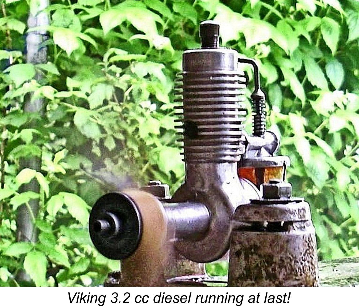
The retail price of this engine was set at 54 kr. However, it does not seem to have attracted much customer interest, since only around 300 examples were reportedly produced. Manufacture seems to have ended in 1951 after only a year or so. Consequently it is a very rare engine today. Claimed output of this model was 0.20 BHP @ 8,000 RPM. If true, the engine delivered a power-to-weight ratio that was well in excess of that developed by the 2.5 cc version. It also peaked at a considerably higher speed. I was hoping to test this claim prior to the initial publication of this article, but as events transpired the engine only arrived a few days before the publication deadline. Nonetheless, I set it up in the test stand right away to attempt to conduct a quick test using a range of suitable props. At that point I was hit with the first of a series of time-consuming problems. Firstly, the pin which secured the prop driver to the shaft sheared off during my initial starting attempts. I replaced it - same problem with the replacement! So I ended up making a split collar mounting for the prop driver, which should have been used from the outset, as it was on the later 2.5 cc models. End of that particular problem...... The next issue was the fact that the contra piston proved to be far too loosely fitted. It was actually following the power piston up and down during starting attempts. So I had to make a new replica replacement, which I lapped to a perfect fit. Another problem solved, but it took time .............
Once going, the engine ran extremely smoothly, never missing a beat. My replacement contra piston turned out to be perfectly fitted, holding its settings firmly while remaining fully adjustable at all times. Needle valve response was also very positive. Given the time pressures under which I was working, I decided to spot-check a few of the same props used in the earier 2.5 cc tests. It was immediately clear that this engine developed considerably more torque than its smaller brother. I got as far as measuring 5,500 RPM on the Zinger 11x7 wood (0.124 BHP), 6,800 RPM on the Top Flite 10x7 Power Point wood (0.156 BHP) and 7,200 RPM on the APC 10x7 (0.167 BHP). However, at this point the glued-on needle carrier fell off! Evidently the glue used wasn't up to the task - it was more of a cosmetic repair. I later repaired the component with JB Weld and then undertook a re-test of the engine. This time I made it through the selected suite of test props, with the results shown below:
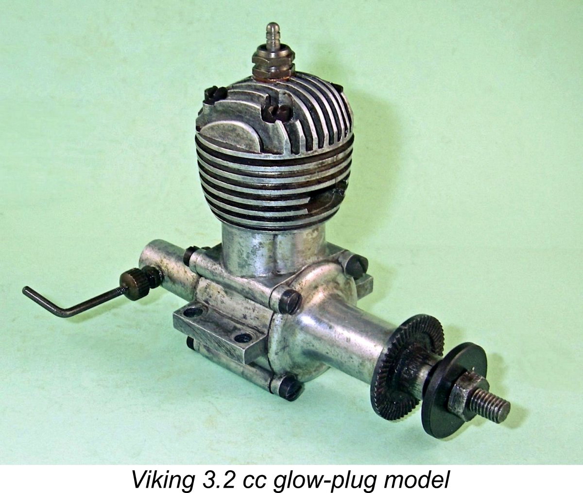
These results confirm that the 3.2 cc model definitely possesses a significant performance advantage over the 2.5 cc version. What's more, it does peak at a somewhat higher speed, just as claimed by the manufacturer. However, the implied peak output of 0.168 BHP @ 7,400 RPM falls well short of the 0.200 BHP @ 8,000 RPM claimed by the manufacturer. Even so, the 3.2 cc diesel should have appeared rather attractive to some owners of the 2.5 cc model, since it was a simple bolt-on replacement for the smaller unit. This created the possibility of gaining extra "urge" at a minimal weight penalty. Rather like the relationship between the original FROG 100 diesel and its larger bolt-on replacement, the FROG 180 diesel, of which more elsewhere. Viking 3.2 Glow-Plug Model – 1952-1954
As with the earlier diesel models, twin bypass/transfer ducts were provided, one on each side. In effect, this was the familiar Cox-style four-port reverse-flow scavenging system. A quality touch was the design of the needle valve assembly, which followed the estabished "racing engine" surface jet pattern by using separate screw-in needle carrier and fuel jet components with an externally-threaded needle. Tension was provided by a split in the needle carrier which in turn was tensioned by a knurled gland thimble. Both elegant and effective!
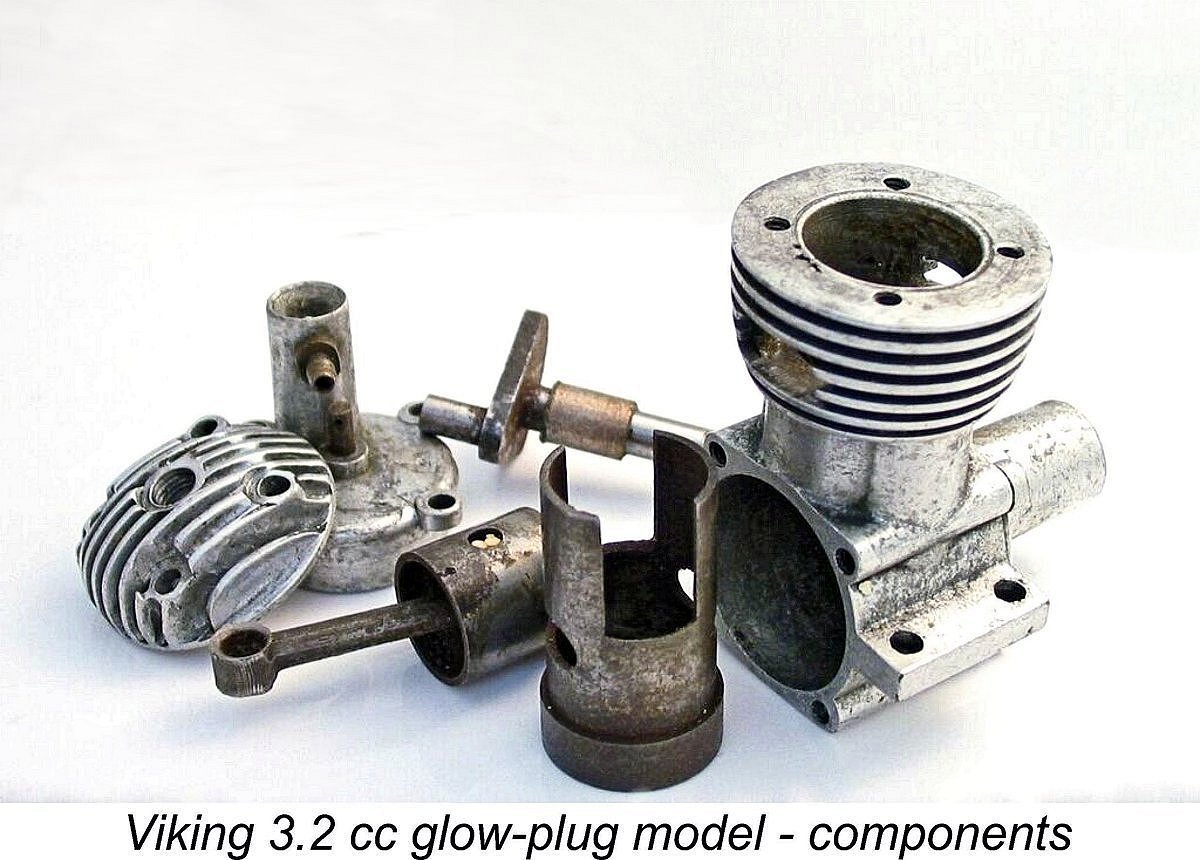
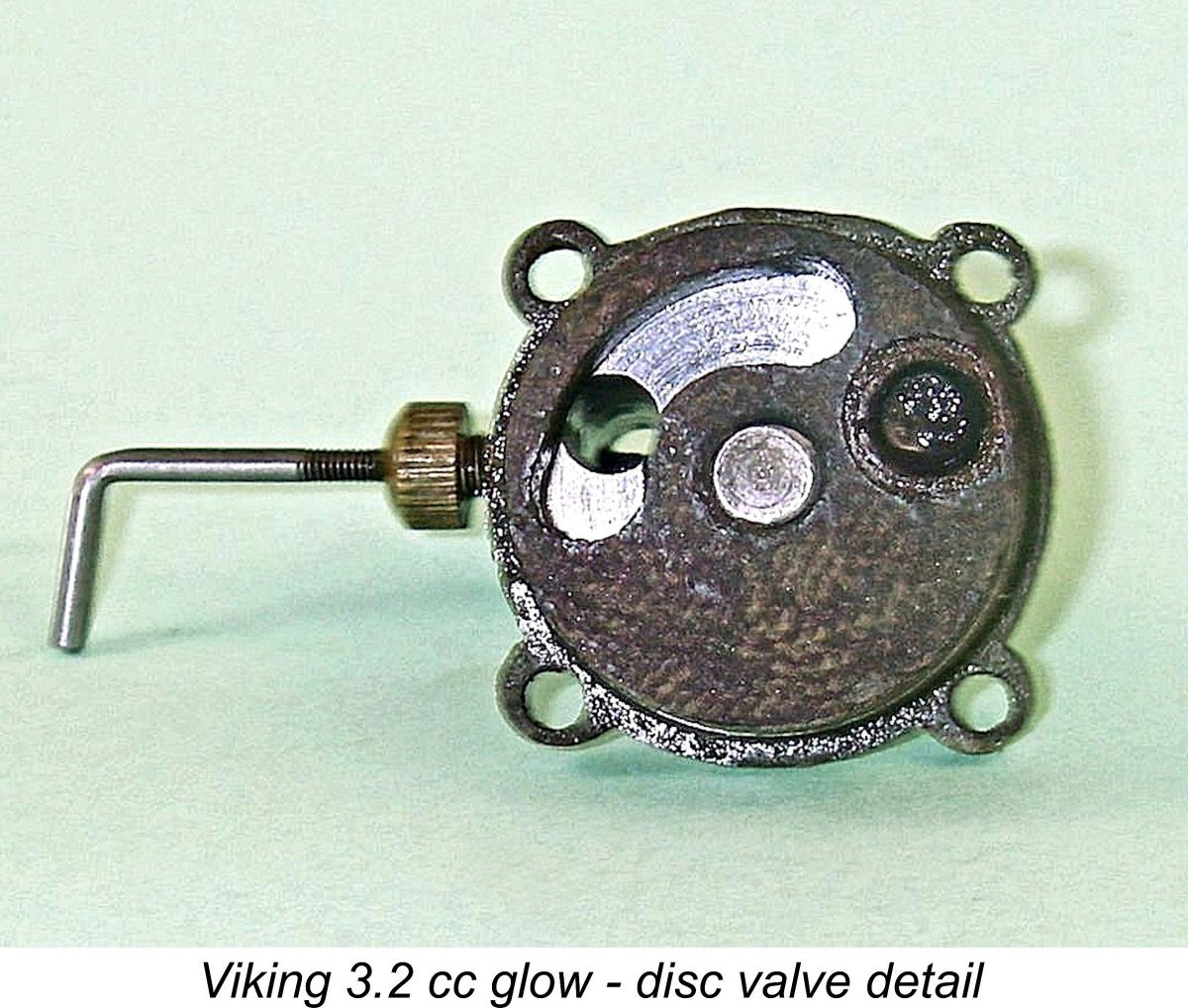
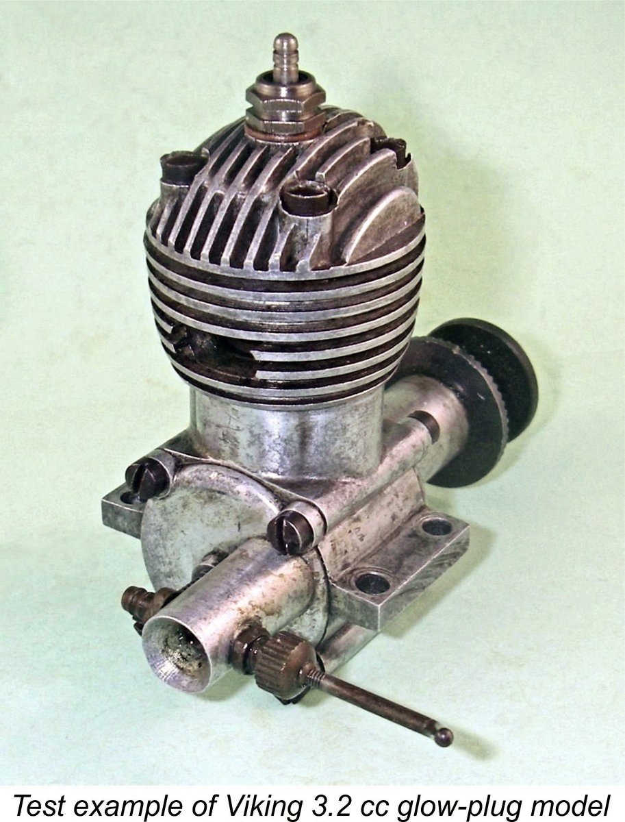
Unfortunately, this model incorporated a few design issues which prevented it from becoming a success. To begin with, it featured a very heavy almost solid cast iron piston which was not conducive to low vibration levels, even with the designer's use of a counterbalanced crankweb. In this, it followed the pattern established previously with the sideport diesel models described earlier. It would appear that Tommerup Clausen had not yet come to appreciate the importance of minimizing an engine's reciprocating weight. In addition, clearance “steps” were milled in the piston crown to serve as deflectors for incoming mixture entering the cylinder via the two transfer ports. The “steps” created in this way destroyed the combustion chamber shape by creating peripheral pockets on opposite sides which limited both compression ratio and combustion efficiency. A volumetric check of the compression ratio of my example gave a figure of only just over 6 to 1, which is very marginal indeed for a glow-plug motor. The crankshaft ran in two bronze bushings inserted from front and rear, but was made a little too flimsy for adequate strength and stability, especially given the very heavy piston with its attendant high reciprocating loadings. Consequently, failures were by no means unheard of. In addition, the lower cylinder liner was made too thin for adequate structural stability, particularly in view of the two long In the case of the 3.2 cc glow-plug model, this issue was alleviated to some degree by the fact that the cylinder was vertically located by a thick annular expansion at the top which bore upon the top of the installation bore in the upper crankcase. This relieved the lower cylinder of any installation stresses. A final issue was the design of the disc rear rotary valve. The disc itself was very nicely machined from some form of laminated plastic material along the lines of Tufnol. This was a very good choice of material given the fact that Tufnol discs operating against aluminium alloy backplates had been shown to wear very well. The problem was that Clausen had clearly failed to appreciate the fact that there was no need to arrange for mechanical pressure to be exerted between the backplate and However, Clausen mounted the disc in this engine on a separate steel spindle which passed through the backplate and was equipped with a fairly strong coil spring retained by a split pin at the rear. This created a considerable amount of continuous mechanical pressure between the static and rotating working faces of the valve. The rear end of this spindle (minus spring and split pin) is clearly visible in the above component view. While the resulting seal was very good indeed even with the engine stopped, the friction drag which this arrangement created was very high. One can feel the drag simply by turning the engine over by hand - it must have cost a considerable amount of power. As a result of all these issues, the engine did not succeed in penetrating the marketplace. It appears that only some 100 examples were manufactured in total, making this an extremely rare and highly sought-after engine today. I'm very much in Luis Petersen's debt for enabling me to acquire my own example. The Viking 3.2 cc Glow-Plug Model on Test
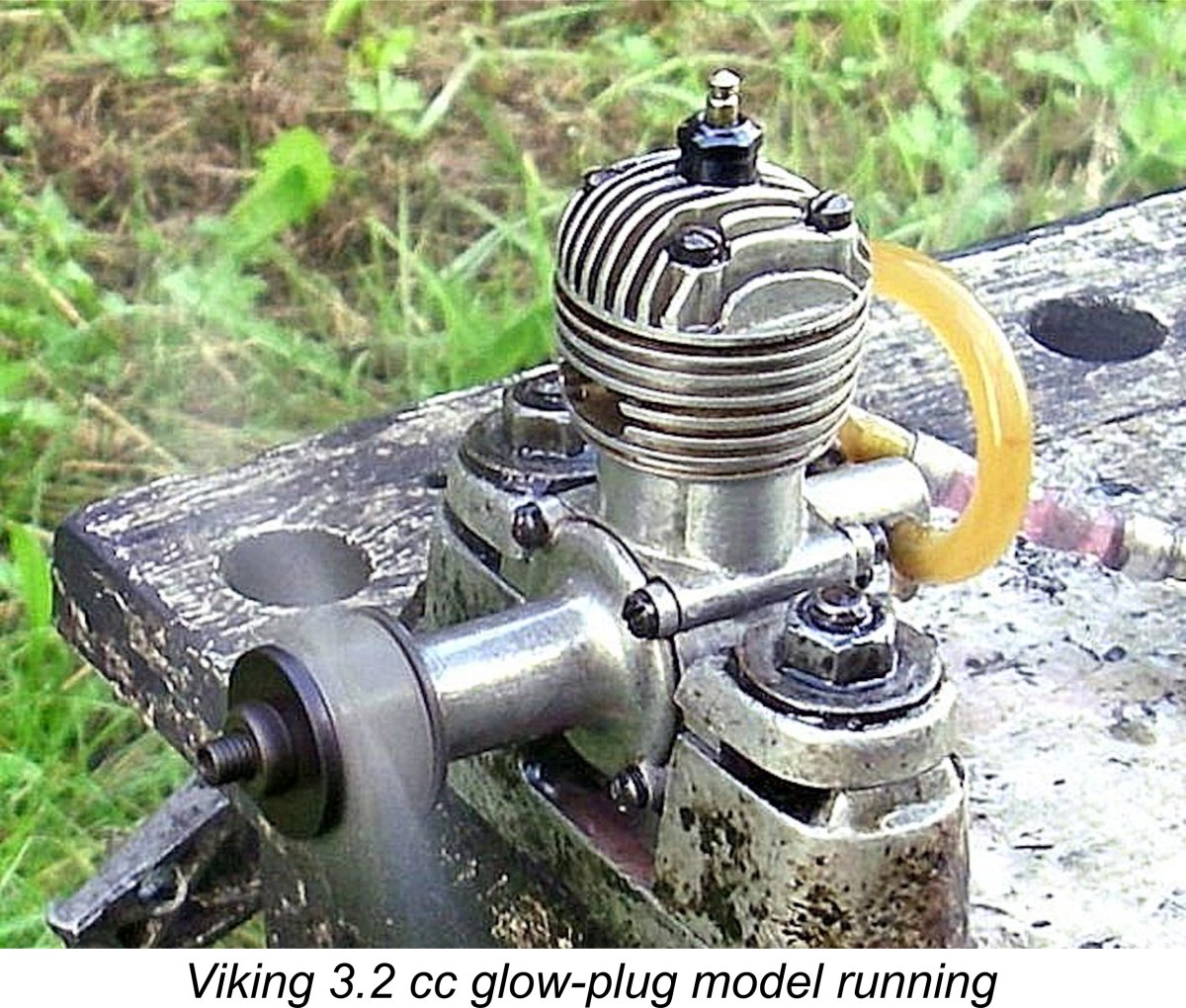
I wasn't expecting this engine to be a powerhouse given the maker's own claims. The combination of the very heavy piston with a rather lightly-built crankshaft led me to decide that I would not push the engine much past the advertised 12,000 rpm. As it turned out, this was an entirely appropriate decision. In keeping with the above considerations, I began with an APC 8x7 airscrew fitted. When turning the engine over slowly by hand, the drag arising from the over-tensioned disc valve was very apparent. However, there it was, and there was nothing that I could do about it. Following an exhaust prime and a few choked “bump” turns to fill the fuel line and check the plug, the engine immediately displayed one of its more endearing characteristics by starting up right away. It was to continue this exemplary starting behavior throughout the test, never requiring more than two or three flicks to start. Once running, the engine quickly settled down, turning the 8x7 prop at a commendably steady 8,900 rpm. Not much power in evidence, but it was shifting a fair bit of air. Running was extremely smooth, with no trace of a misfire and no tendency to sag. The one fly in the ointment was a very noticeable degree of vibration – the poor old test stand was getting quite a shaking! Speeds continued to climb as the loads became lighter. Response to the needle valve was very positive, making the establishment of the optimum setting a very simple matter. Starting and running qualities continued to be beyond reproach, but the vibration issue understandably worsened as speeds rose. Nonetheless, I persisted, finally obtaining the following results:
The two WB props are wide-blade airscrews specially created by cutting down larger APC items to fill some glaring gaps in my set of calibrated test props. As can be seen from the above data, the engine had obviously begun to run out of puff by around 12,000 rpm. The two smallest props tested clearly demonstrated that it simply didn’t want to run much above that point. The figures reported above imply a peak output of around 0.206 BHP @ 11,700 rpm - a little less on both counts than the manufacturer’s claim, although not greatly so. The Viking glow-plug model was certainly considerably more powerful than its 3.2 cc diesel companion in the range.
This was an extremely frustrating exercise, because my long experience with model engines leads me to believe very sincerely that this engine has a far greater potential than it showed on this test. The induction, transfer and exhaust arrangements all speak to a relatively strong performance potential. If I had been planning to actually use one of these units, the first thing that I would have done is to set the piston up in a milling machine and mill away much of the piston interior to lighten it, leaving the bosses intact. I sincerely believe that this would have considerably improved the engine’s ability to run faster while at the same time greatly reducing operating stresses upon the conrod and crankshaft. I would also have modified the disc valve mounting to eliminate the very considerable drag imposed on the engine by the overly-powerful and quite unnecessary spindle tensioning spring. The best approach would probably be simply to fit a machined tubular spacer of the correct length in place of the spring. Alternatively, one could fit a shorter or far lighter spring. This would still leave the matter of the inefficient combustion chamber unresolved. However, given the presence of those two piston cutaways there’s really not much that can be done about this unless one were to make a new head from scratch. If these modifications were carried out, I could readily envision the engine equalling or even exceeding the manufacturer’s performance claim and doing so at a greatly enhanced level of reliability. It’s a great pity that Tommerup Clausen failed to appreciate these problems and their very obvious solutions. He had a potentially excellent design here, but one which was quite unable to show its true potential as released. Viking 0.75 Red Helm (Red Head) diesel – January 1955 – 1963?
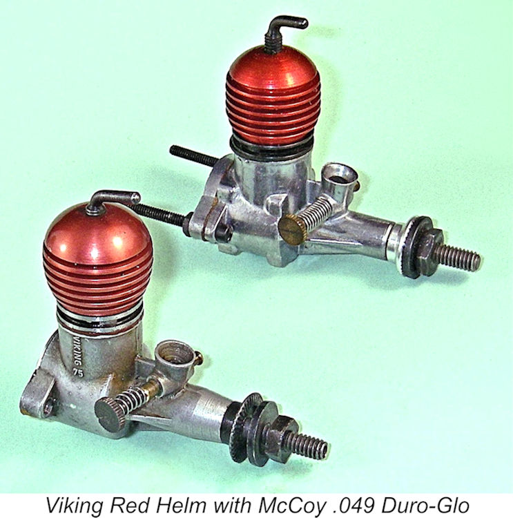
The Red Helm weighed in at 42 gm. The manufacturer made no specific power output claim for this model, instead contenting himself with stating that peak power was delivered at 14,000 rpm. The engine sold at a retail price of 54 kr. Unfortunately, this model too suffered from a serious design defect. Wishing to avoid the use of the McCoy’s O-ring contra-piston, Clausen elected instead to use a steel contra piston which was stamped from steel plate. This component frequently (but not invariably) leaked quite badly, as a result of which the Red Helm quickly acquired a rather poor reputation among modellers due to the starting difficulties which often resulted from this leakage. Small diesels are hard enough to start on high-speed props without a handicap of this sort! Clausen evidently came to recognize this problem, since some of the later examples had conventional turned and lapped contra pistons. These engines were very dependable performers, but by then the damage to the engine’s reputation had been done. Thanks to this issue, the Red Helm never became a strong seller. Production typically averaged only some 25 units in three weeks, and at times it was much less. During the engine’s relatively long production life extending from January 1955 to around 1963, only about 2,000 examples were reportedly made in total, presumably in small intermittent batches as dictated by demand. No performance information was ever published. The Viking Red Helm 0.75 cc Diesel on Test
The matter rested there for some years. Eventually, in 2025 I assembled a small group of engines requiring skilled intervention to get them going, sending them along to my good mate Peter Valicek of the Netherlands. Among them were my stash of Red Helm parts, with a request to Peter that he do what he could to get one or both represented examples running. As some of you may know, Peter is one of the most skilled engine restorers on the planet. He took up the challenge with his usual competence - you simply wouldn't believe how well he restored the sorry basket-case example of the Taifun Hobby RS that was included in the package! I still can't believe it myself! Peter did just as well with the Viking components, creating not one but two really nice examples of the engine. One of these retained some visible evidence of its former hard life, while the other (seen in the above images) was restored to near-new condition. Amazing work by my mate Peter!! Both examples featured the notorious stamped contra-piston, although in both cases that component did its job perfectly, showing no evidence of undue leakage.
I mounted the engine on a piece of extruded aluminium angle material that had seen good service with other small radially-mounted engines, including the McCoy .049 Duro-Glo diesel. I decided to begin with an APC 7x6 prop and work up the RPM scale from there. The fuel was a 40/35/25 mix of kerosene, ether and castor oil with 1½% added cetane booster. The engine proved to be perfectly fitted, having excellent compression with almost no play in the bearings - great job, Peter! It started quite easily once I discovered that a small exhaust prime was more or less essential - finger-choking alone or the old drop of fuel down the intake trick didn't do it. The best approach was found to be to choke just enough to fill the fuel line, administer a small exhaust prime and start flicking. Using this approach, the Red Helm was an unfailingly prompt starter. Once running, the engine performed flawlessly throughout the test, running absolutely smoothly when properly set, with minimal levels of vibration. Response to the controls was very progressive without being overly sensitive. Power output too was unexpectedly impressive, as witness the following data obtained after a suitable running-in period.
Overall, I was very impressed with this neat little engine. It's actually a great pity that the somewhat dubious service record of the stamped contra-piston rather blighted its reputation, since a well-fitted example like that tested was an above-average 0.75 cc diesel which ran superbly and handled very well. If they had all been as good as my test example and had received wider circulation, they would be fondly remembered today as one of the best 0.75 cc diesels of the 1950's. Viking 2.48 Super diesel – 1956-1963?
Bore and stroke of this model were 14.55 mm and 15.0 mm respectively for an actual displacement of 2.49 cc. The engine weighed a commendably light 118 gm (4.16 ounces), although this low weight was achieved at the expense of a certain fragility. Claimed output was 0.24 BHP @ 14,000 rpm. The engine sold for a retail price of 69 kr. Unfortunately, this model perpetuated some of the design flaws of other Viking models, notably the Red Helm. The contra piston followed the same pattern by being formed as a steel stamping. This component was prone to leakage, just as it had been with the smaller model. Later examples had turned and lapped contra pistons to deal with this issue. However, the engine’s overall construction was too light for adequate distortion resistance and durability. The original crankshafts manufactured by Clausen proved to be somewhat undependable, but durability was later improved through the use of forged shafts which were produced elsewhere by a sub-contractor. Production of this model typically averaged around 25 units in two weeks. A total of about 3000 units were reportedly manufactured in total. Conclusion As the above review will have shown, the Viking range was bedevilled throughout its life by a succession of design flaws which appeared on various models. The one model which appears to have been relatively free from major design issues was Tommerup Clausen’s first design, the 2.5 cc sideport diesel. That said, even that model had its Achilles' Heels in the form of its excessively heavy piston and distortion-prone cylinder liner.
If Clausen had been able to shake off a few design tendencies such as the application of excessively light and over-simplified construction plus the use of excessively heavy pistons, the range might well have fared better in the long run. However, that was not to be. Regardless, the Viking venture has left us with a number of highly servicable engines which careful owners can still enjoy today. In closing, Luis and I would like to extend our thanks to everyone who assisted in the preparation of this article. Luis wishes to extend special thanks to “Mr. DMI” Svend Schou, whose scrapbook has been an invaluable source of information. However, we don’t claim to know it all! If any reader can offer corrections or additions to the text, please get in touch! ______________________________ Article © Adrian C. Duncan & Luis Petersen First published May 2016 Updated October 2018 Second update June 2026 - test of Red Helm |
||
 In a number of articles to be found on this website, I've recounted the histories of some of the more prominent model engine manufacturers to appear in the Scandinavian countries. These articles have included coverage of the
  My initial intention was merely to edit Luis’s article into colloquial English and present it verbatim with his permission. However, Luis himself comprehensively derailed this plan by succumbing to a fit of enthusiasm which led him to send me a significant amount of additional information on early Danish engines other than the Viking models! He also provided a great deal of photographic and documentary material which had not appeared with his original 1990 effort.
 During the 1980’s, Luis Petersen and Jens Geschwendtner began to take an interest in the history of the Viking range. One of their goals became to assemble as complete a collection of the engines as possible for display in their local Technical Museum. Failing that, they at least wanted to find opportunities to examine and photograph representative examples.
 It turned out that he was a great source of information because he had been apprenticed at the workshop of Christian Tommerup Clausen (generally referred to as just Tommerup Clausen), who made the Viking engines. Those who have a Viking Red Helm engine may have noticed the letters CTC on the side?
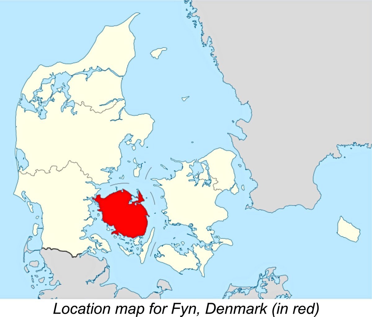 So the Viking marque remains alive and well on the flying fields of Denmark, 66 years after its establishment. No doubt Tommerup Clausen, who died a few years ago, would be very happy to know this!
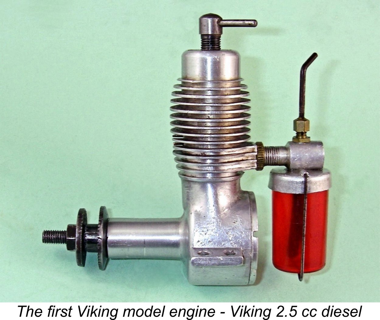 The first Viking engine, a 2.5 cc sideport design of which much more later, was constructed by Clausen at the beginning of 1950 following consultation with some members of the Odense Model Flying Club. It was inspired by the earlier
 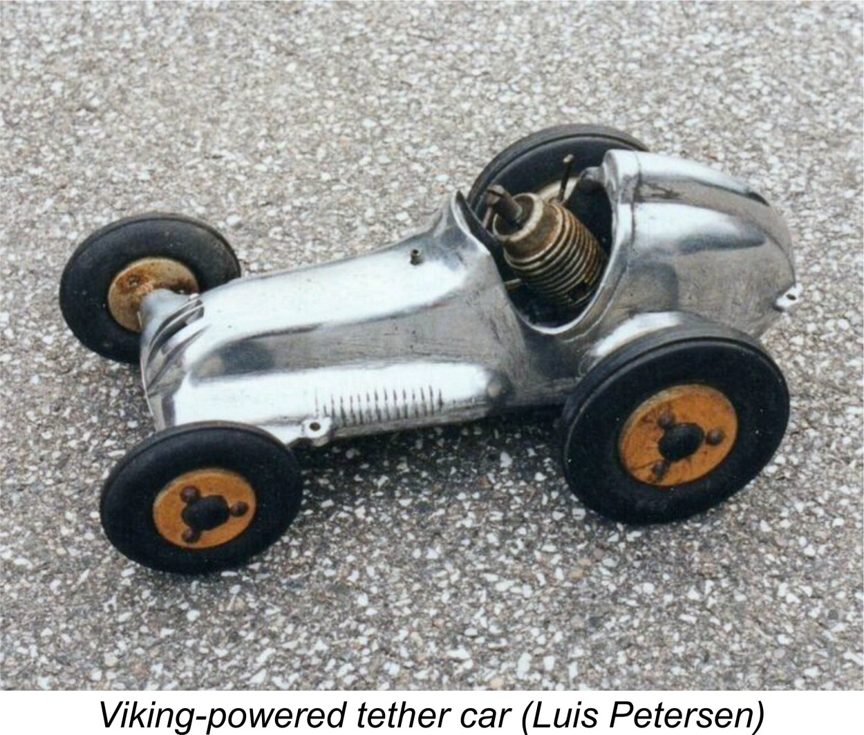 number of protruding wires of various lengths fixed to it. A given length and thickness of wire has its own resonant frequency at which it vibrates. Clausen established a standard for his engines, and each engine could be checked using this device to ensure that it met the standard by causing the appropriate wire to vibrate while running.
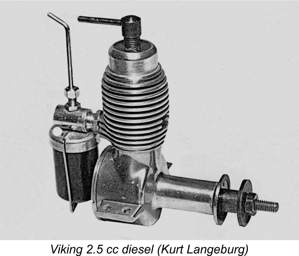 This well-made and in some ways considerably out-of-the-rut sideport model is the design for which the Viking name (and indeed the Danish model engine manufacturing industry) is best known today in the world outside of Denmark. It was both the first and last model engine produced by Tommerup Clausen’s factory, remaining in production throughout the life of the Viking model engine range from 1950 to 1969.
  can think of were the
 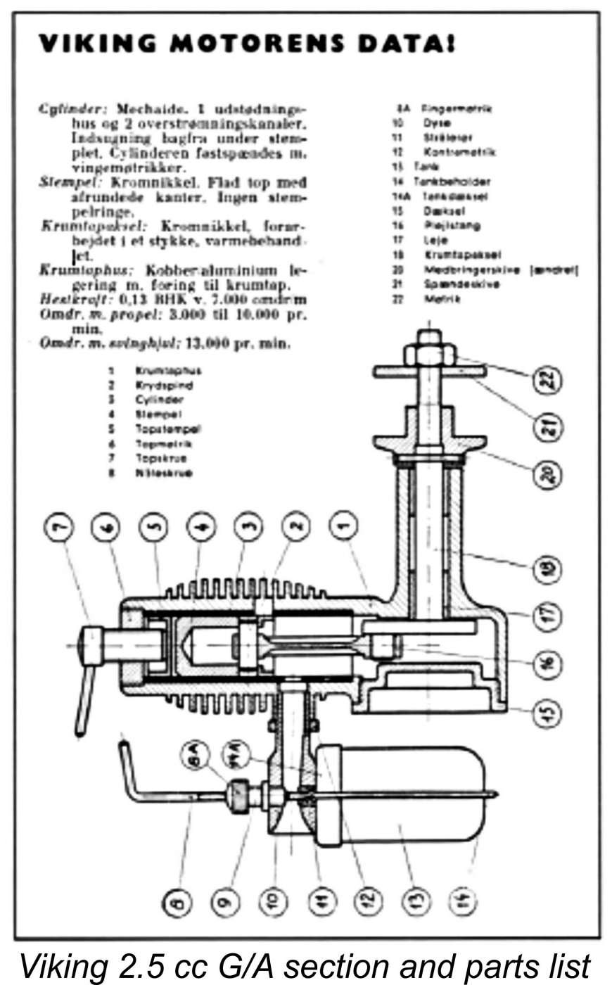 The cylinder porting design of the Viking was also copied more or less directly from that of the Thorning III. This included perhaps both models' most unusual feature, namely a single forward-facing exhaust port, which can be clearly seen in the attached images. This feature was well out of the rut in 1950, but it did reappeared much later in high performance Russian team race diesels. The intention there was to place the hottest region of the cylinder in the least obstructed direct cooling air-flow. It would of course have the same effect when applied to the Thorning and Viking designs.
 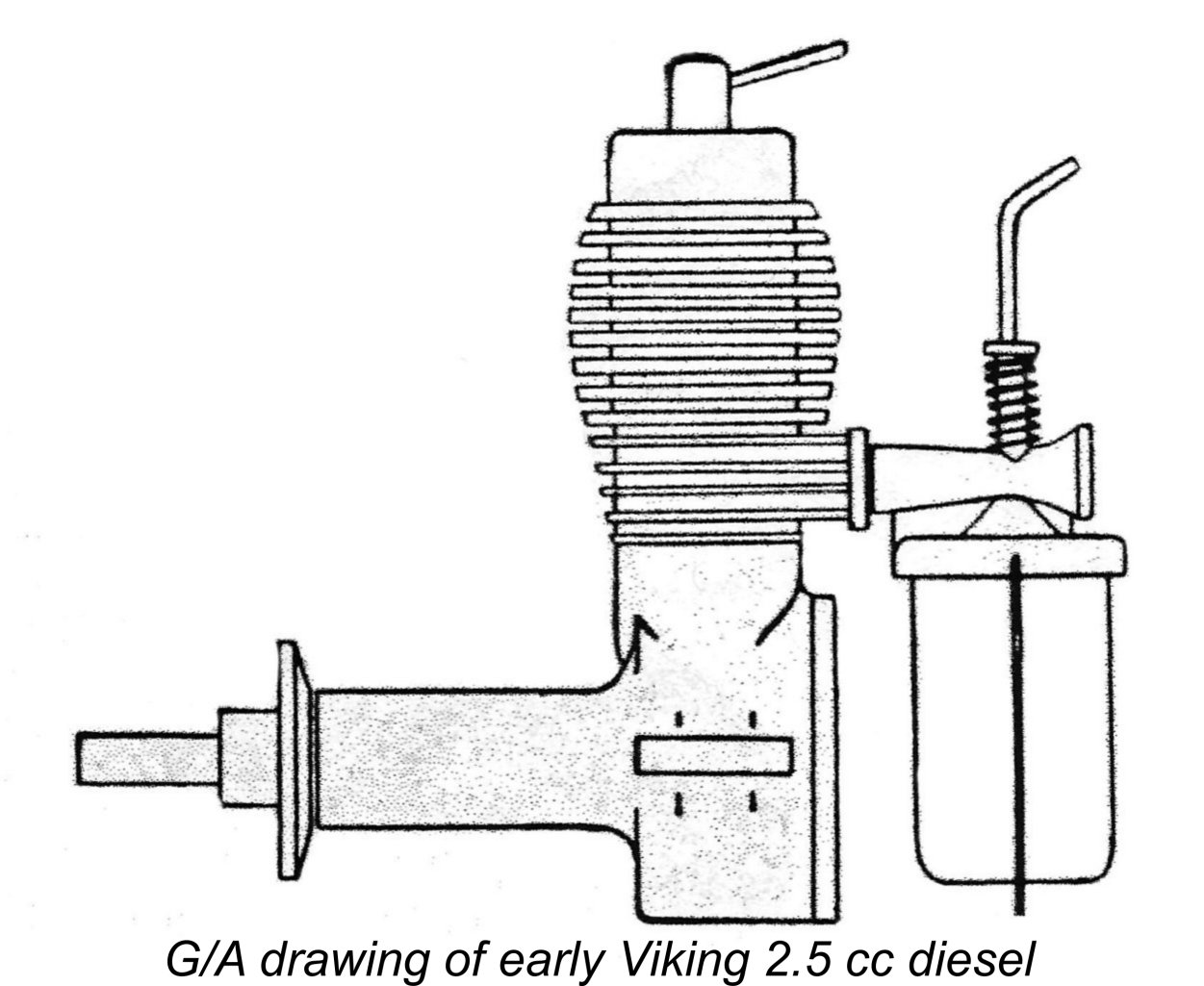 carrier for the needle. The needles used with this carburettor were fitted with a disc which bore against a coil spring fitted around the needle carrier to provide the required needle tension for security of settings. Hopefully this arrangement will be made sufficiently clear by the attached G/A drawing of one of these early models. The later section of this article dealing with the Viking 3.2 cc diesel shows an example of that model with the cast carburettor unit fitted - see below.
 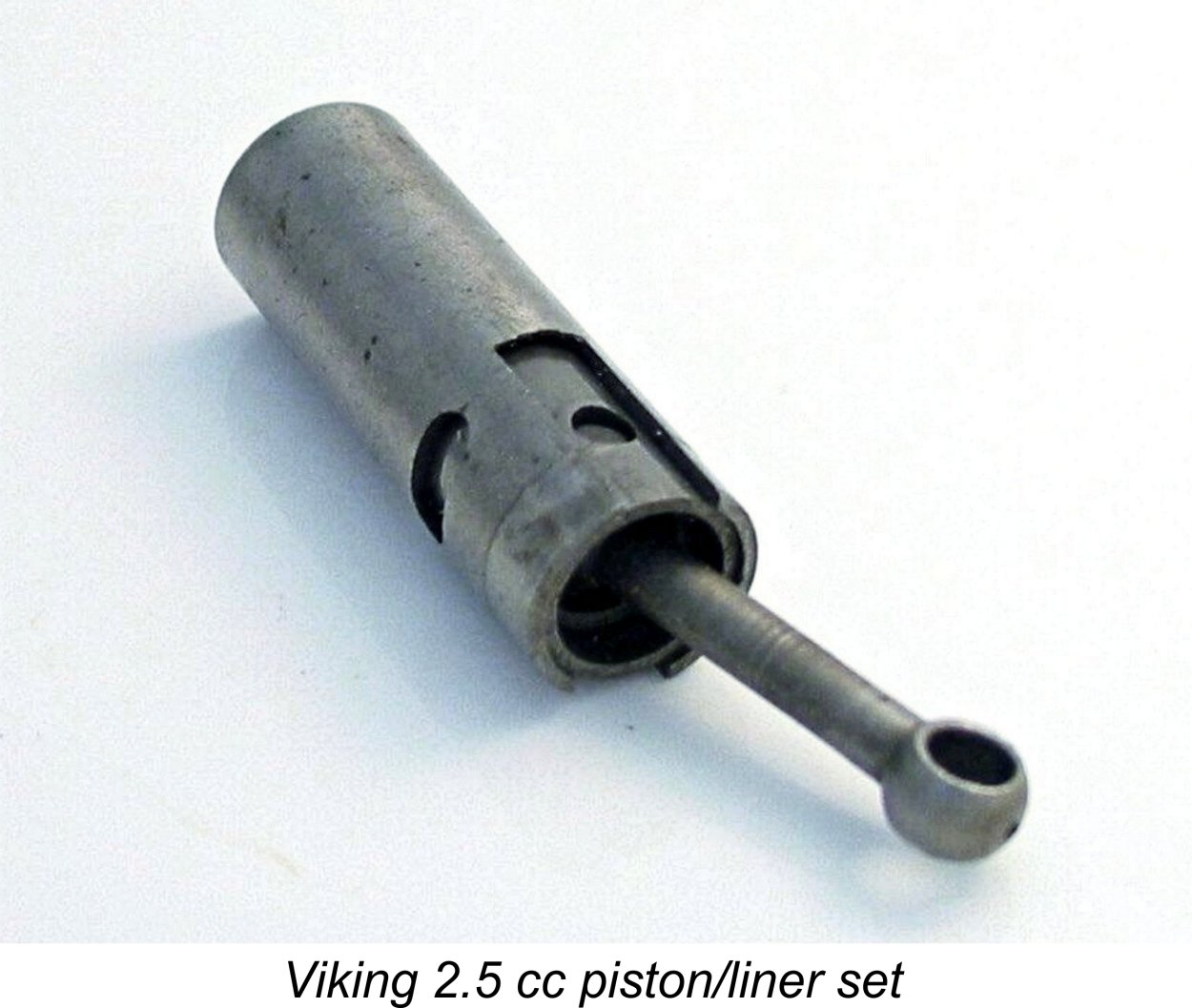 One criticism which may fairly be levelled at this point is the weight of the piston. That component together with its pressed-in gudgeon pin and steel con-rod weighs all of 16 gm. That's a lot of reciprocating weight for a long-stroke 2.5 cc engine like this, and one would expect this unit to be a serious vibration producer despite the counterbalanced crankweb with which the crankshaft is provided.
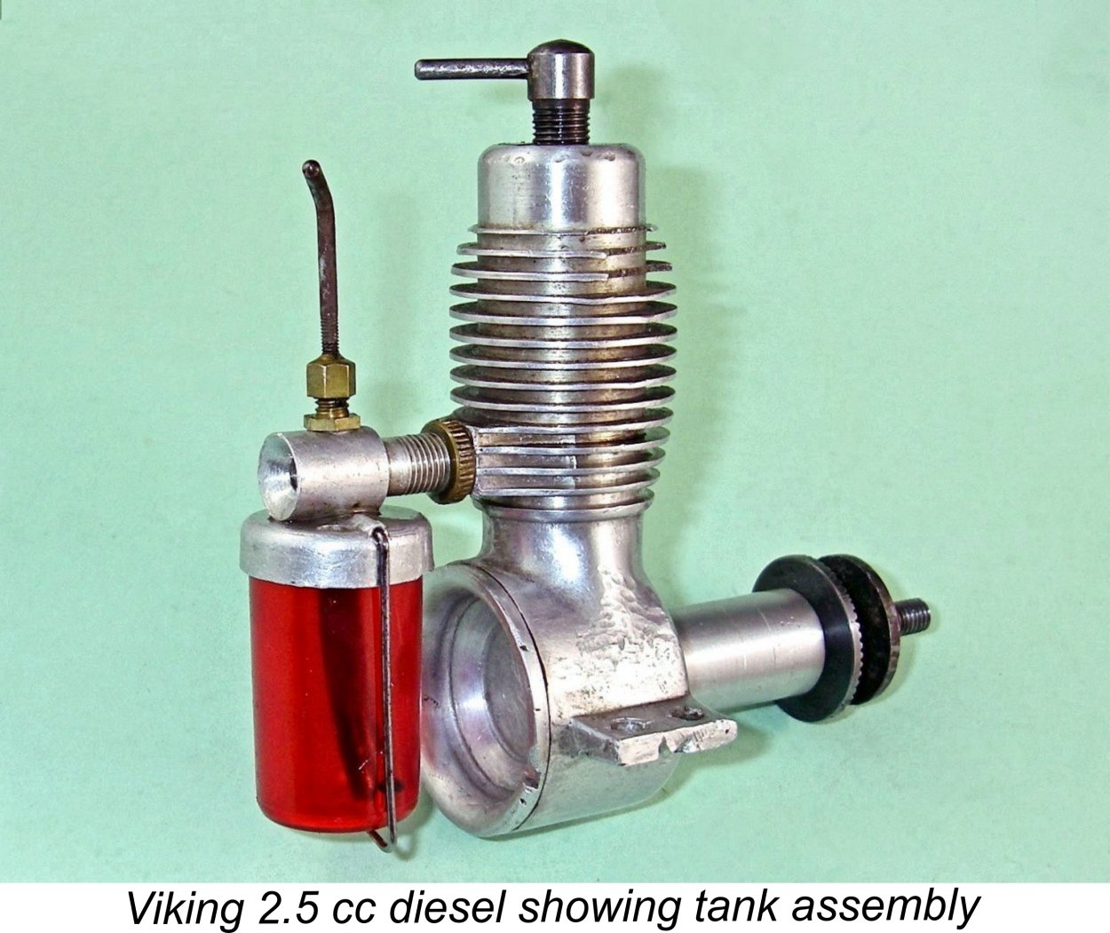 Throughout its long production life, the engine was little changed, implying that the designer got it more or less right at the outset. There were a few hiccups, however. The early models featured a light alloy prop driver which was secured with a pin through the shaft, but this proved to be inadequate since the stress concentration which it created led to a rash of broken crankshafts. The prop driver mounting arrangements were accordingly changed to a far more secure taper-on-shaft system with a steel prop driver. Incidentally, the original configuration was apparently copied directly from the Dyno 1.
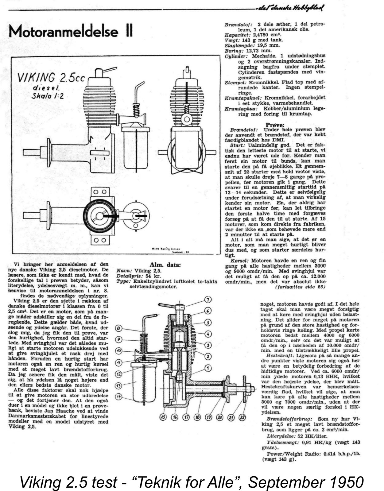 The Viking 2.5 cc diesel was the subject of a published test which appeared in the September 1950 issue of the previously-cited Danish magazine "Teknik for Alle". It was the second such test to be published in the magazine, as indicated by the Roman numeral "II" in the heading.
 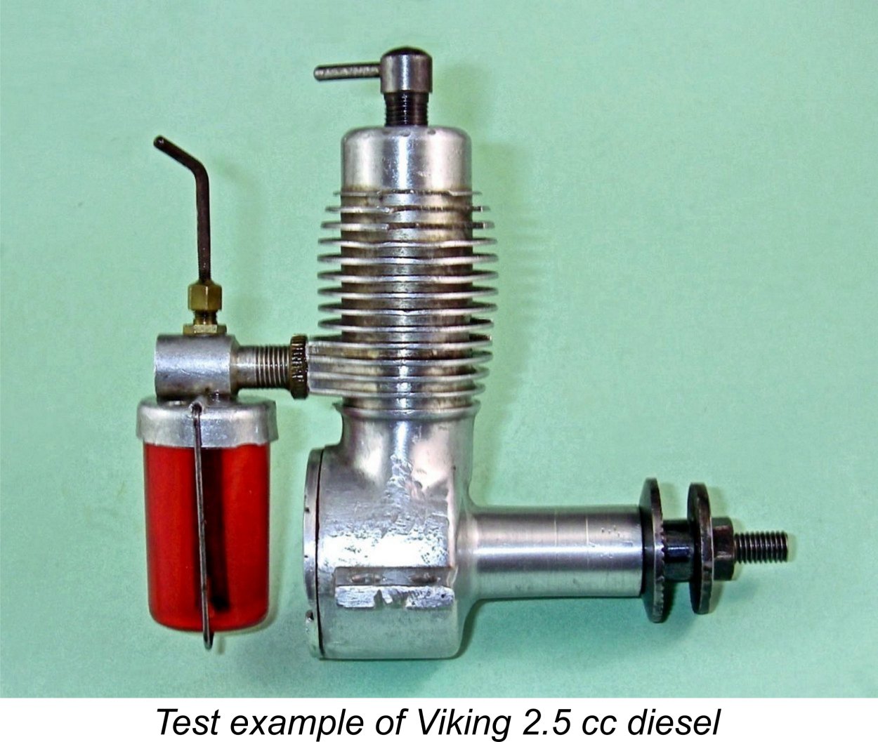 a club, but even so it should clearly be a much faster prop than any 11x6! The implication was that the engine peaked at a somewhat higher speed than 6,000 RPM! In my view, the limiting factor would probably be the vibration issue resulting from the combination of a very heavy piston and a very long stroke.
 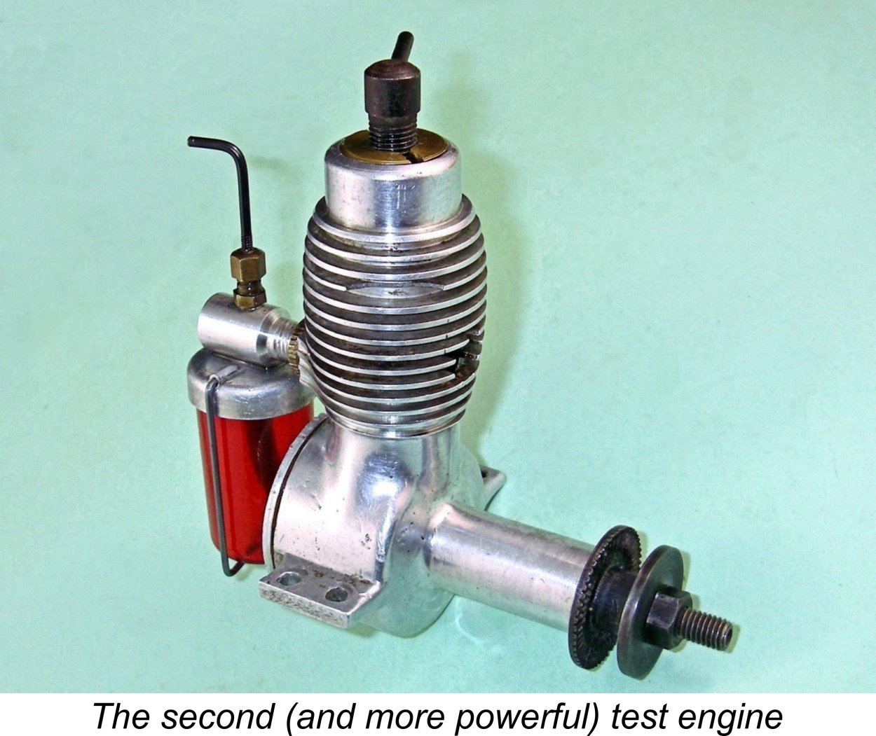 sense.
 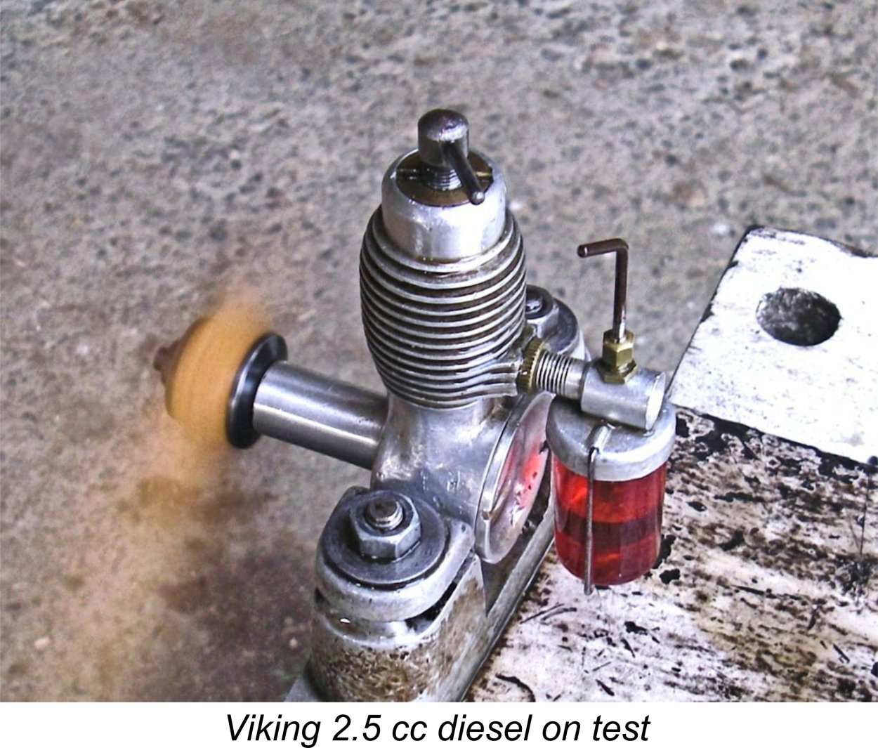 A few things soon became apparent. One, excessive choking was to be avoided during cold starting! I found that it was quite easy to flood the crankcase using this method. To get the engine going from cold, the best approach seemed to be to give a single choked flick to fill the fuel line and then administer a modest prime through the exhaust port. If this was done, the engine invariably started almost immediately. For hot restarts, the prime could be omitted.
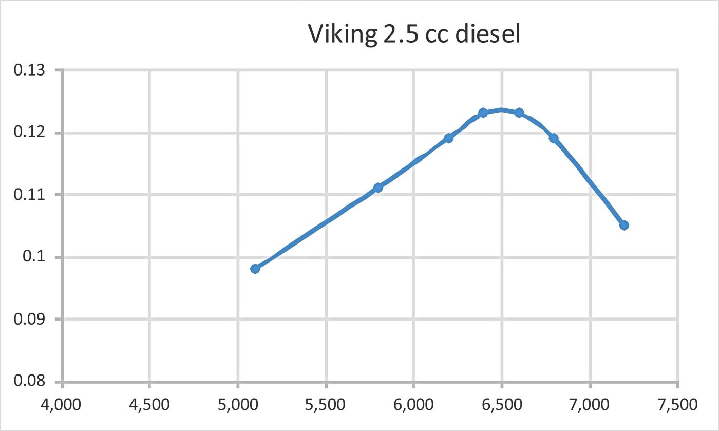
 This is the model which started Luis’s previously-noted late 1980's quest for information. It was basically a bored-out version of the 2.5 cc engine described above, nominally retaining the same stroke of 19.50 mm but utilizing a larger bore of 14.4 mm for a displacement of 3.18 cc.
 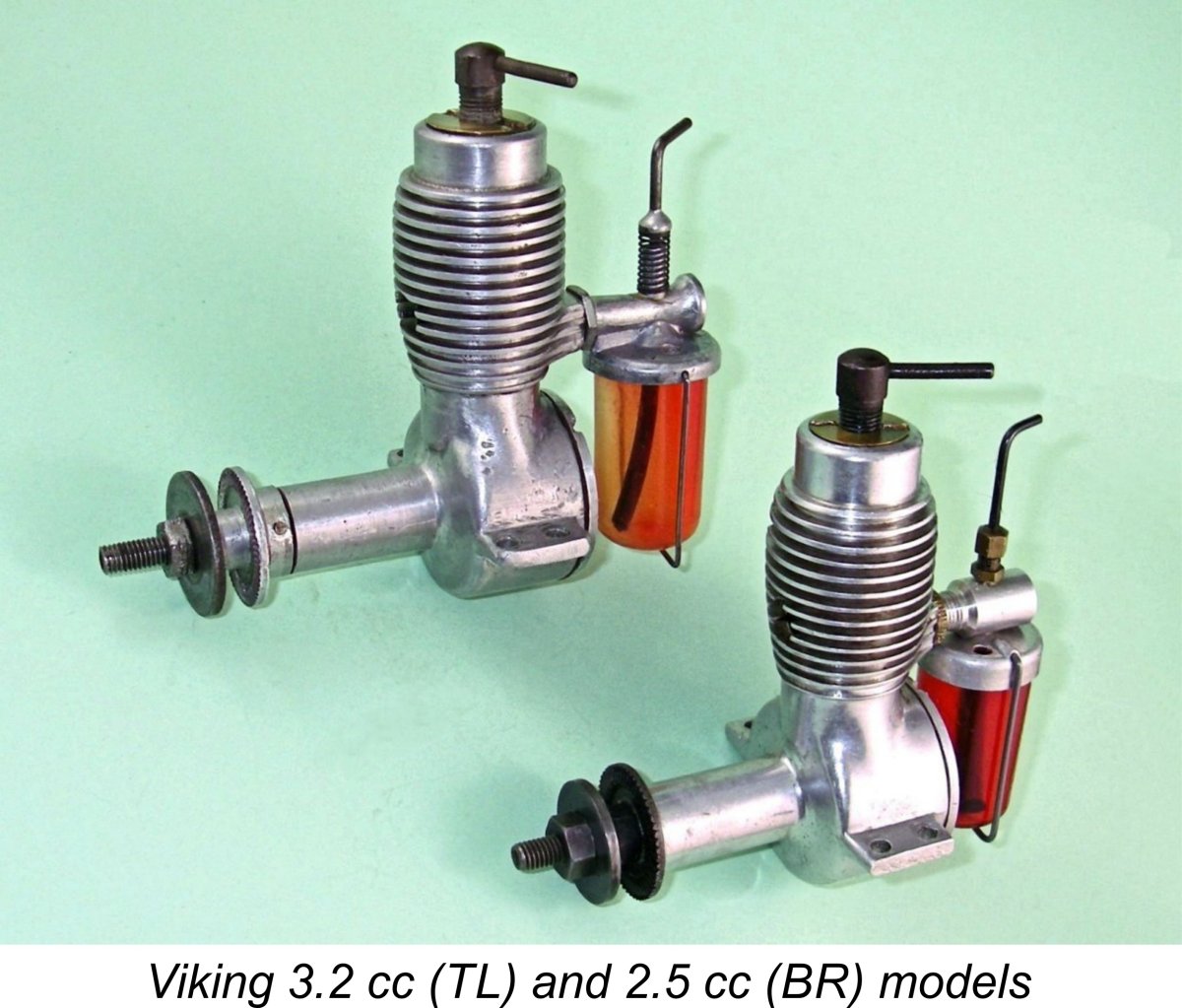 All examples of this engine were fitted with the original pinned alloy prop driver, also featuring the early combination of a cast carburettor and a blue plastic tank. As noted in our description of the Viking 2.5 cc model, the cast carburettor was all too prone to breakage, and this example is no exception - the needle carrier has been broken off at some point in its previous history. The necessary repair has been very neatly effected using an adhesive of some kind. The original blue tank has been lost and has been replaced with a later red plastic component. Apart from that, the engine remains completely original.
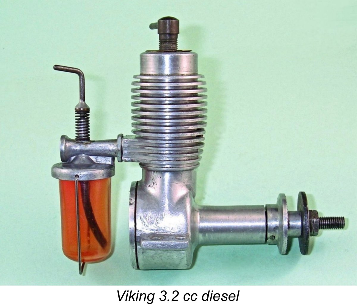
 All of this left me with only a few hours available before the deadline! Even so, I set the Viking up again with the intention of doing a quick 'n dirty test for this article. The engine proved to be quite well worn, with rather "soft" compression seal around the power piston. I found that as with one of my tested 2.5 cc models, an oil prime really helped when it came to starting, although the engine would start without that treatment. Despite the handicap of the soft compression, I'd rate this as every bit as good a starter as its 2.5 cc sibling. The same technique of a single choked flick and a prime was the way to go.
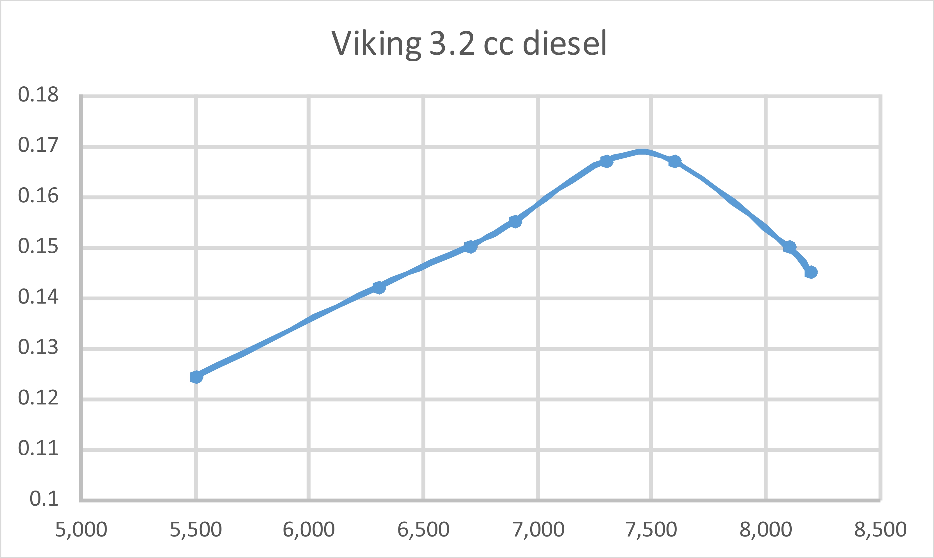
 This design represented Clausen’s first step towards the modernization of the Viking range. It was a graceful-looking glow-plug motor of generally up-to-date design featuring rear disc valve induction and reverse-flow scavenging. It retained the unusual forward-facing exhaust port location which had characterized the earlier diesel models, but took practical advantage of the absence of the sideport induction tube by adding a second matching exhaust port at the rear. Both exhaust ports were unusually large.
 Some time after the original publication of this article, I finally got around to testing the fine example of this very rare engine that had been so kindly supplied by Luis Petersen. I used a "hot" plug in deference to the engine's rather low compression ratio. Since most Danish modellers in the early 1950's would have had very limited access to high-nitro fuels, I went with a 10% brew. Even that was probably somewhat on the high side .........
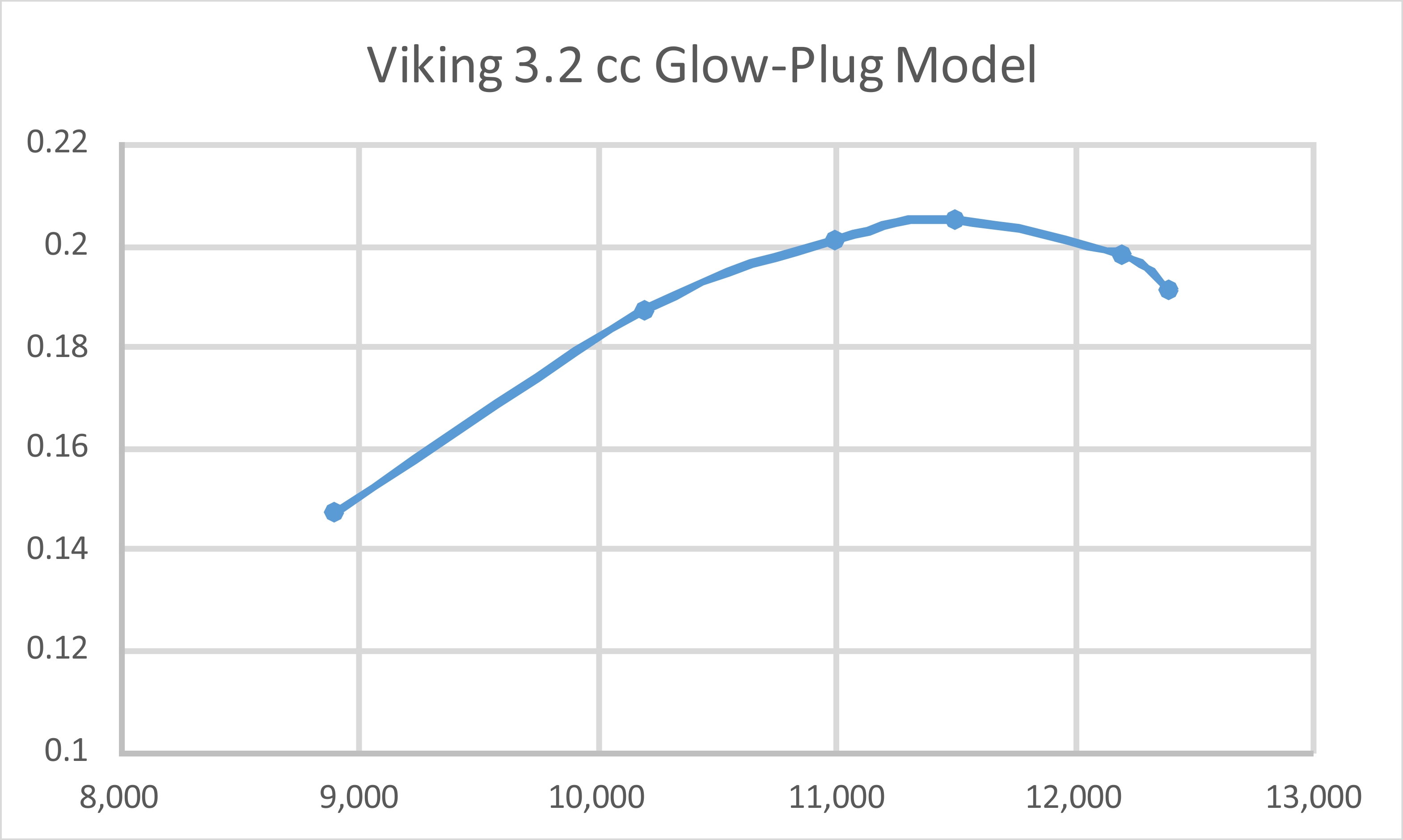
 Readers who are familiar with American diesels will spot this one right away as more or less a direct copy of the 1953
 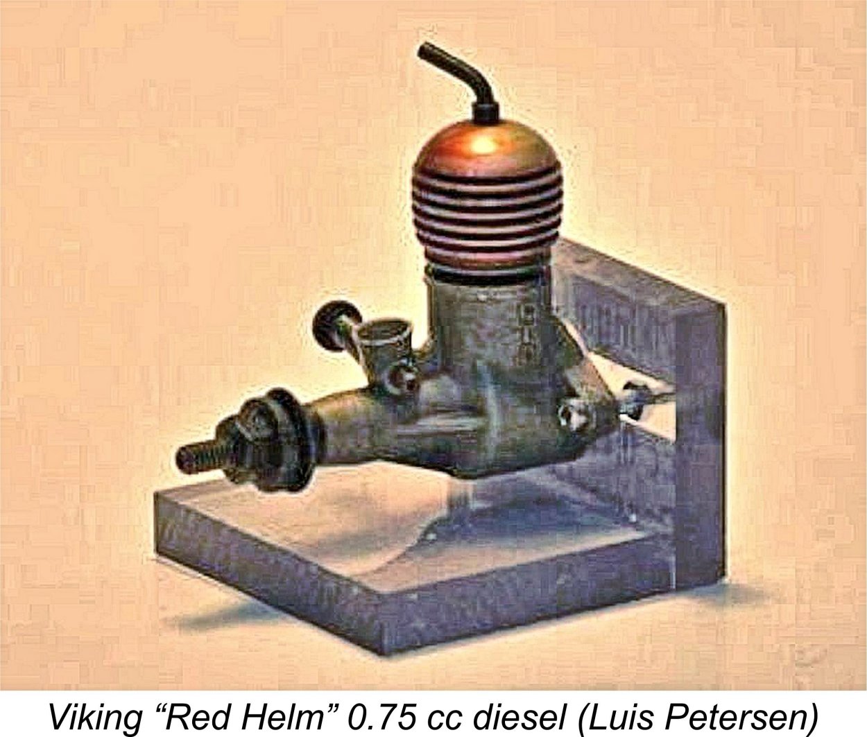 During our initial collaboration on this article in 2016, Luis Petersen was kind enough to send me an assortment of Viking Red Helm components. There was almost enough material to make up two examples of the engine, although most of the working parts were seemingly well used or damaged, while a few other components were missing altogether. Naturally, this made it impossible to assemble a complete running example.
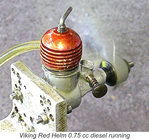
 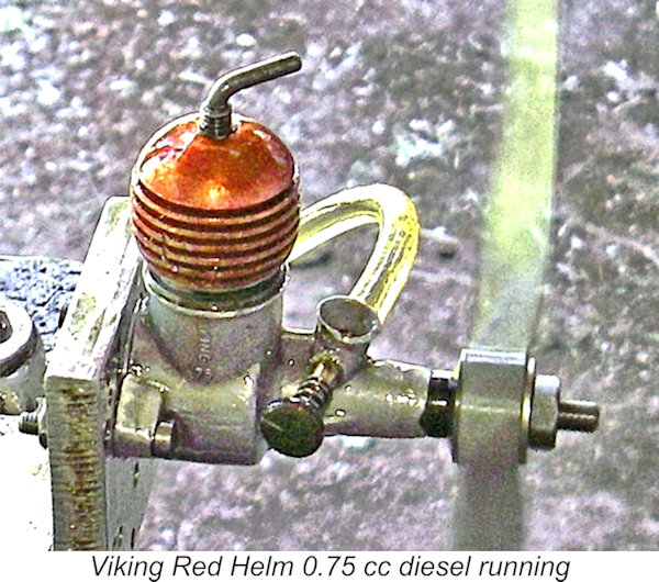 Now having two fully operable examples of this engine on hand, I felt obliged to put one of them through a full bench test - couldn't let Peter's amazing work go to waste! During the course of his post-restoration testing, Peter had confirmed that the somewhat more "used-looking" example was the stronger performer by a considerable margin, so I decided to use that example as my test subject.
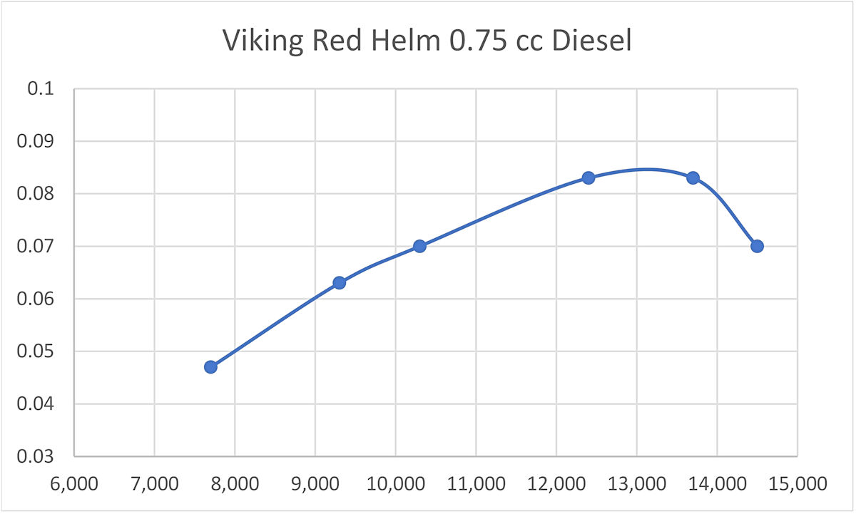
 As can be seen, the little Red Helm proved to be an above-average performer for a diesel of its displacement, developing a peak output in the vicinity of 0.085 BHP @ 13,200 RPM. These figures actually exceed the 0.079 BHP @ 12,500 RPM reported by Ron Warring in
 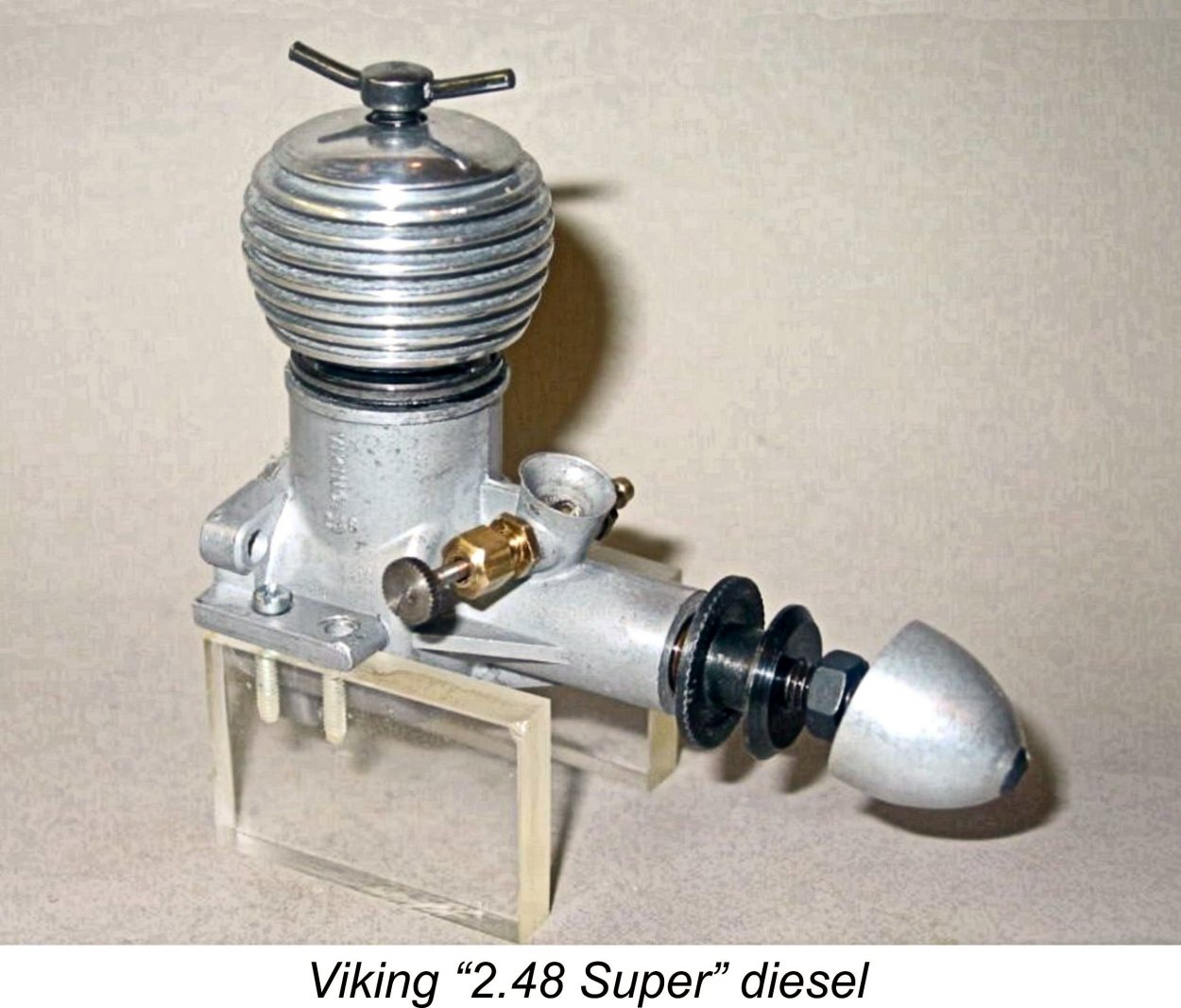 In 1956, Clausen introduced a 2.49 cc model called the Viking 2.48 cc Super which was in effect an enlarged version (without the red head) of the Red Helm 0.75 cc design which had been introduced in January of the previous year. The engine actually bore a marked similarity to the contemporary Webra engines from Germany.
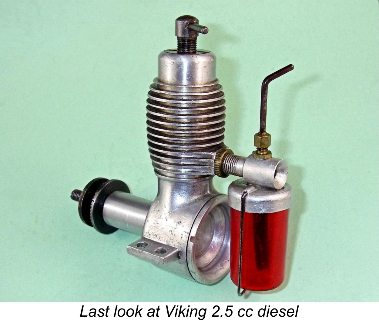 This almost certainly explains the fact that by the end of 1963 that original 2.5 cc diesel was the sole member of the Viking range to remain in production. The fact that it survived for another 6 years all the way to 1969 is a testament to its qualities in the eyes of the Scandinvian modelling community. Indeed, it is mainly the success of that model that has given the Viking range the honoured place that it holds today in Danish aeromodelling history.
| |